Article

Real-Time Localization and Mapping Utilizing Multi-Sensor Fusion and Visual–IMU–Wheel Odometry for Agricultural Robots in Unstructured, Dynamic and GPS-Denied Greenhouse Environments

1
College of Artificial Intelligence, Nanjing Agricultural University, Nanjing 210031, China
2
College of Engineering, Nanjing Agricultural University, Nanjing 210031, China
*
Author to whom correspondence should be addressed.
Agronomy 2022, 12(8), 1740; https://doi.org/10.3390/agronomy12081740
Submission received: 30 June 2022 / Revised: 21 July 2022 / Accepted: 22 July 2022 / Published: 23 July 2022
(This article belongs to the Special Issue AI, Sensors and Robotics for Smart Agriculture)

Abstract

:
Autonomous navigation in greenhouses requires agricultural robots to localize and generate a globally consistent map of surroundings in real-time. However, accurate and robust localization and mapping are still challenging for agricultural robots due to the unstructured, dynamic and GPS-denied environmental conditions. In this study, a state-of-the-art real-time localization and mapping system was presented to achieve precise pose estimation and dense three-dimensional (3D) point cloud mapping in complex greenhouses by utilizing multi-sensor fusion and Visual–IMU–Wheel odometry. In this method, measurements from wheel odometry, an inertial measurement unit (IMU) and a tightly coupled visual–inertial odometry (VIO) are integrated into a loosely coupled framework based on the Extended Kalman Filter (EKF) to obtain a more accurate state estimation of the robot. In the multi-sensor fusion algorithm, the pose estimations from the wheel odometry and IMU are treated as predictions and the localization results from VIO are used as observations to update the state vector. Simultaneously, the dense 3D map of the greenhouse is reconstructed in real-time by employing the modified ORB-SLAM2. The performance of the proposed system was evaluated in modern standard solar greenhouses with harsh environmental conditions. Taking advantage of measurements from individual sensors, our method is robust enough to cope with various challenges, as shown by extensive experiments conducted in the greenhouses and outdoor campus environment. Additionally, the results show that our proposed framework can improve the localization accuracy of the visual–inertial odometry, demonstrating the satisfactory capability of the proposed approach and highlighting its promising applications in autonomous navigation of agricultural robots.

1. Introduction

Agricultural robots are widely used nowadays to provide people with an alternative solution to conduct repetitive and high-risk operations in many indoor and outdoor agricultural environments [1,2,3,4]. However, the ability of agricultural robots to navigate or move autonomously has always been a challenge due to the complexity of agricultural environments, especially the Global Positioning System (GPS)-denied greenhouses [5,6,7,8,9]. Localization, mapping, path planning and obstacle avoidance are the essential capabilities for robots to navigate from the starting point to the destination autonomously and successfully. Among them, localizing accurately and generating a globally consistent map of the surroundings in real-time are critical tasks to improve the performance of agricultural robots [10]. Therefore, it is crucial to propose an efficient and accurate real-time localization and mapping method to meet the needs of autonomous navigation in agricultural environments.
Simultaneous Localization and Mapping (SLAM) is defined as a process for a robot to localize itself without previous knowledge of the environment while constructing a map of its surroundings [11]. SLAM is considered a key technology for robots in autonomous navigation and the basis of augmented and virtual reality (AR and VR) applications [12]. SLAM can be divided into two main categories from the perspective of sensors: Lidar SLAM and Visual SLAM. Lidar SLAM was widely studied and applied to many robotic applications such as autonomous navigation over the past three decades [13,14]. However, single-line Lidar SLAM can only provide two-dimension (2D) information about the environments to robots, leading to the inadaptability for subsequent space obstacle avoidance, and multi-line Lidar SLAM costs too much. Therefore, Visual SLAM has become a hot topic in the mobile robot community, especially in the robot autonomous navigation research domain, due to the low cost of the cameras and rich information from the images [15,16]. To decrease the complication and expense of the autonomous mobile robots, Wang et al. [17] presented an efficient, yet economic and simple localization and navigation method with ORB-SLAM, one of the most successful SLAM systems based on Oriented FAST and Rotated BRIEF (ORB) features for robot pose estimation [18] for indoor service robots. The method achieves reasonable localization and navigation accuracy in indoor environments. Xu et al. [19] proposed a Visual SLAM-based localization system that is suitable for a wide range of applications in GPS-denied indoor environments. One of their contributions was that their system can switch between the SLAM mode and localization mode flexibly as needed while the robot is exploring the environment. Nevertheless, it is difficult for the system to run in complex environments including severe illumination variations or highly repetitive features. To deal with Visual SLAM problems for scenarios with dynamic objects, Fang et al. [20] integrated semantic segmentation results into the ORB-SLAM2 framework to remove moving objects, and, hence, reduce the impact of feature points mismatching and finally improve the accuracy of pose estimation in a healthcare facility.
Traditional Visual SLAM methods only perform well in simple indoor environments or urban environments with obvious structural features [21]. However, the accuracy and stability of systems are highly influenced by outdoor environmental conditions such as varying illumination, less texture, rough roads, etc. Therefore, multi-sensor fusion approaches are studied extensively to compensate for visual defects and provide robots with more accurate localization results. To improve the navigation performance in terms of accuracy and continuity in urban environments, Afia et al. [22] proposed an integrated low-cost navigation system by fusing information from an Inertial Measurement Unit (IMU), a Global Navigation Satellite System (GNSS) receiver, a Wheel Speed Sensor and a vision module based on monocular SLAM. The method decreases the drift when GNSS is unavailable and improves the navigation solution when GNSS measurements are corrupted. Alliez et al. [23] developed a multi-sensor wearable SLAM system for indoor and outdoor localization in highly dynamic environments. They introduced a novel LiDAR–Visual–Inertial–GPS fusion localization strategy via the Kalman Filter to compensate for the lack of robustness of each sensor when applied to dynamic sceneries. Lin et al. [24] proposed a framework with high-rate filter-based odometry and a low-rate factor graph optimization. The framework takes advantage of measurements from LiDAR, inertial and camera sensors and fuses them in a tight-coupled way. By tightly fusing different types of sensors, the algorithm is robust enough to deal with various visual failures and LiDAR-degenerated scenarios.
The SLAM-related technologies are also increasingly used in agricultural environments to achieve real-time localization, mapping and navigation in recent years [25]. To create a fully autonomous mobile robotic platform and provide useful services to farmers, Post et al. [26] proposed a cost-effective robotic rover platform based on Robot Operating System (ROS). The results obtained from laboratory and field testing show the current successes in applying the low-cost rover platform to the task of autonomously navigating the outdoor farming environment. Focusing on farming outdoor navigation applications, Galati et al. [27] used a modified version of the Extended Kalman Filter (EKF) to obtain a full 3D (6DOF) pose estimation by combining measurements from wheel odometry, IMU sensor and visual odometry. Moreover, terrain classification is performed to allow the robot to run safely during the navigation by checking the differences between the 2D occupancy grid map generated by Lidar SLAM and the 3D point cloud map generated by Visual SLAM. Experimental results are presented to validate the system and show its effectiveness in relevant agricultural settings. Astolfi et al. [28] developed a navigation system applied to vineyard environments by taking advantage of wheel encoders, IMU, GPS, and Lidar-based SLAM and Adaptive Monte Carlo Localization (AMCL) algorithms. The system has an accurate and robust pose estimation and the ability to build navigable maps despite a rough and complex vineyard scenario.
However, unlike traditional agricultural environments, greenhouses are not only characterized by large-scale unstructured and constantly changing illumination [4], but also GPS is ineffective because of the shelter of greenhouses, and crops grow faster than in outdoor agricultural scenes. Therefore, accurate and robust localization, mapping and navigation for agricultural robots in unstructured, dynamic and GPS-denied greenhouses remain challenges. In this paper, a state-of-the-art loosely coupled Visual–IMU–Wheel odometry fusion method was proposed for robots to realize accurate and robust real-time localization and mapping in greenhouses. The specific objective of this study involves the following components:
  • Estimating the pose of the robot singly using wheel encoders, IMU and Visual SLAM;
  • Integrating the estimation result of each sensor into a loosely coupled multi-sensor fusion framework to achieve accurate localization;
  • Generating a dense 3D point cloud map of surroundings on the basis of fused pose estimation output.

2. Materials and Methods

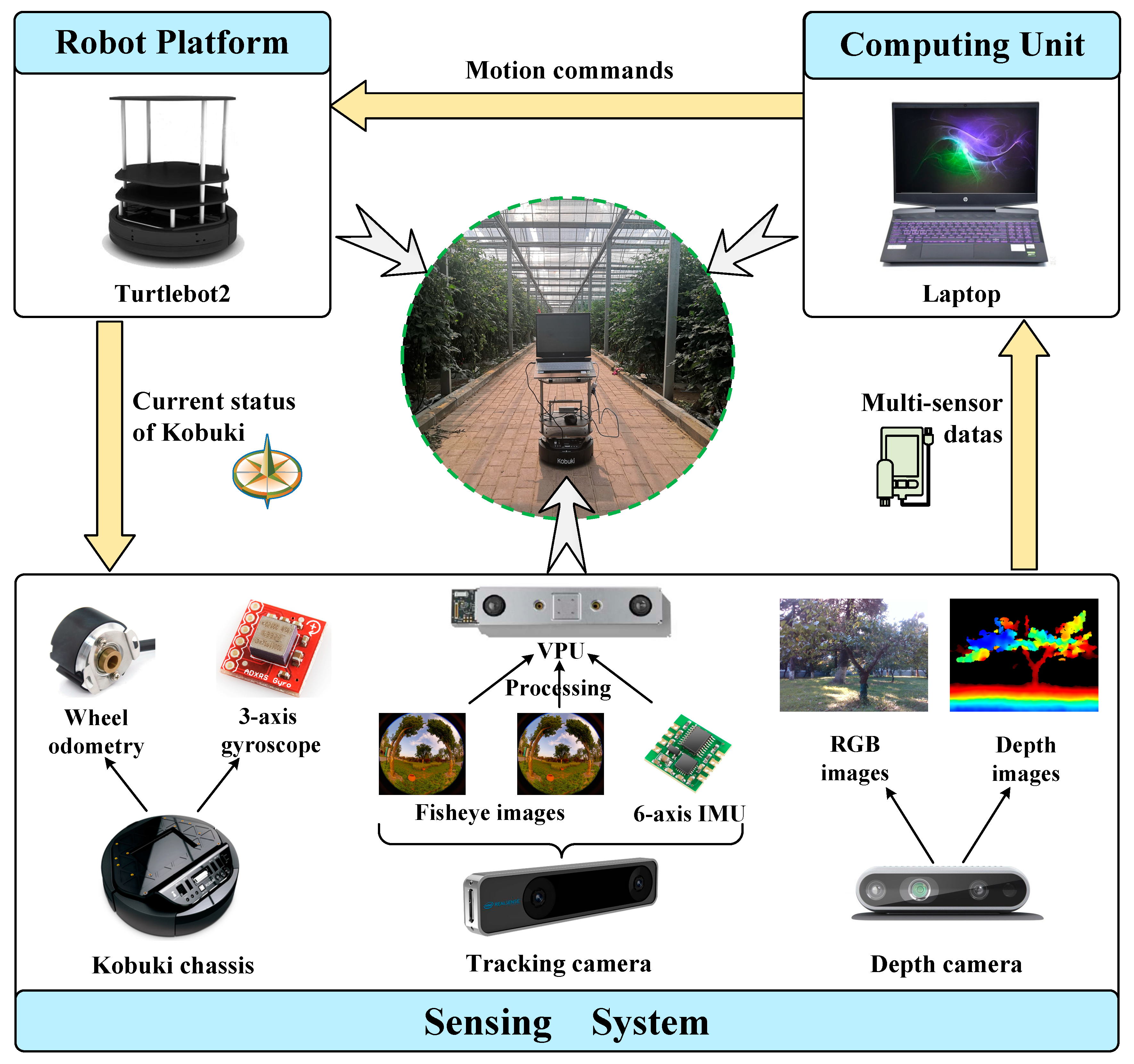
2.1. ROS-Based Real-Time Localization and Mapping System

The hardware platform of the proposed localization and mapping system mainly includes three parts: mobile robot platform, sensing system and computing unit. An overview of the localization and mapping system is shown in Figure 1.
The mobile robot platform used in this study is Turtlebot2, which has an affordable cost and open-source software. Turtlebot2 is built upon the mobile base called Kobuki, with wide sharing sensors installed to achieve localization and navigation [29]. With two driving wheels, two training wheels, and each wheel having a drop sensor, Turtlebot2 is suitable to drive in both indoor and outdoor environments.
The sensing system consists of a stereo camera, an IMU, wheel encoders, and a depth camera. The stereo camera is decided as the Intel Realsense T265, composed of two fisheye lens cameras, an inertial measurement unit and an Intel visual processing unit (VPU). The field of view (FOV) of the two fisheye lens cameras is close to hemispherical 163 ± 5°. The VPU fuses input from the fisheye lens cameras and the inertial measurement unit to provide a highly accurate real-time position with low power consumption [30]. The IMU and wheel encoders in the sensing system are directly provided by the Turtlebot2. The IMU includes a three-axis digital gyroscope with a measurement range of ±250°/s and the wheel encoders are accurate enough. The Intel Realsense depth camera D435i is chosen to complete the mapping task. The depth camera provides RGB and depth images of its surroundings with a framerate of 30 fps [31]. The practical range of the depth camera can reach up to 16 m [32], so it is helpful to create a visual 3D map of large-scale greenhouse environments.
The laptop used to run the multi-sensor fusion localization and mapping algorithms is equipped with an Intel(R) Core (TM) i7-10870H, 2.20GHz CPU and 16GB RAM. The algorithms are implemented in the Ubuntu 16.04 LTS operating system running ROS Kinetic and the development language is C++.

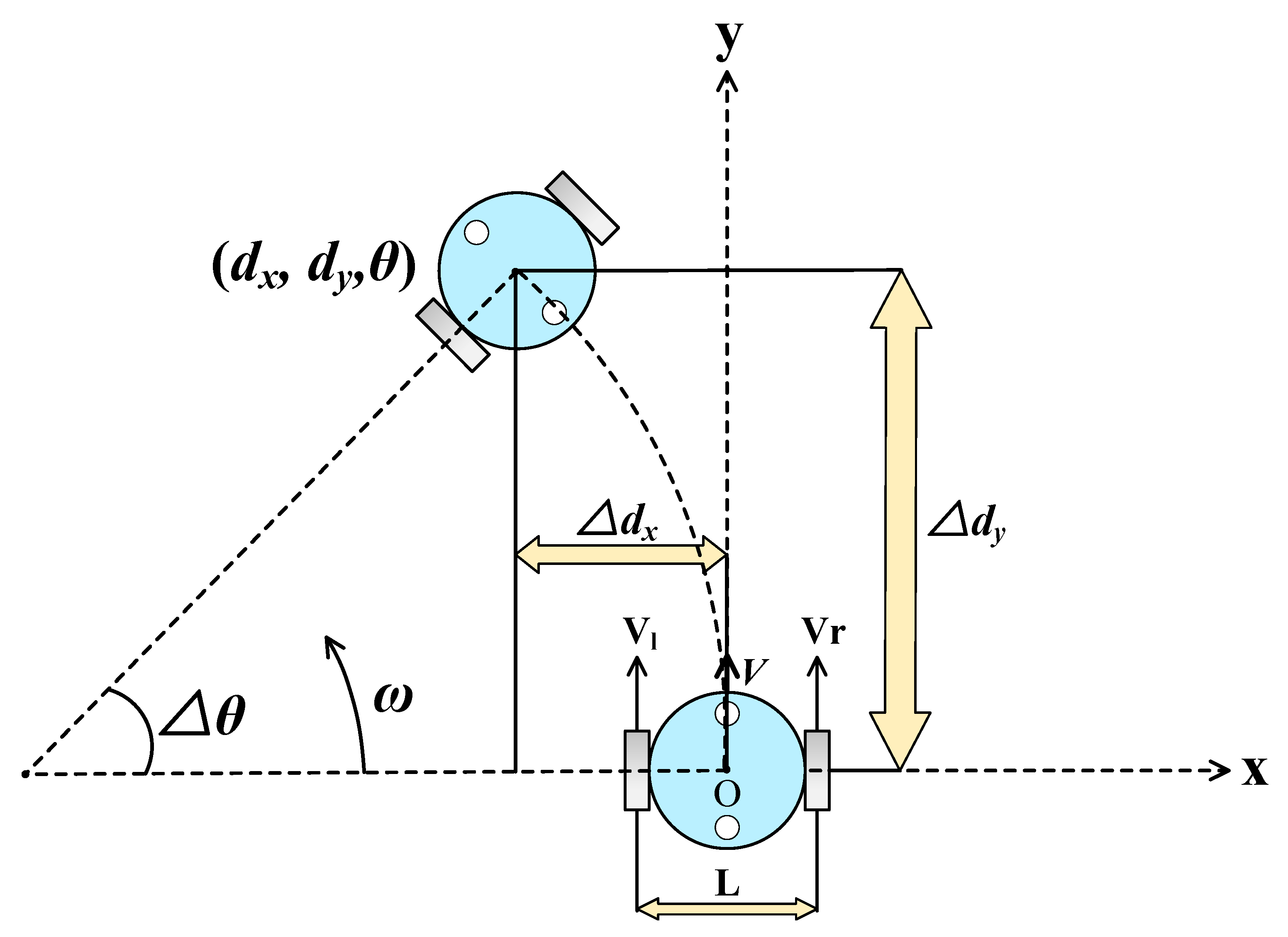
2.2. Wheel Odometry Measurement Model

According to the motion characteristics of the kinematic mobile robot, we construct the motion model. Figure 2 shows the kinematic model of the two-wheel differential robot for motion deduction [33,34]. Vl and Vr are the linear velocity of the left and right wheels, respectively. L is defined as the length between the left and right wheel. Then, the linear velocity V of the robot can be calculated by Formula (1)
V = V l + V r 2
The angular velocity ω of the robot can be calculated by Formula (2)
ω = V r V l L
The wheel odometry of the robot refers to the cumulative calculation of the position and heading of the mobile robot at any time in the world coordinate system from the starting point O (0,0). During the time sample Δ t, the distance d the robot moves forward can be calculated by Formula (3)
d = V     Δ t  
Then, the distance the robot moves along the x-axis Δ dx and y-axis Δ dy can be calculated by Formula (4) and Formula (5), respectively.
Δ d x = d c o s θ = V     Δ t c o s θ
Δ d y = d s i n θ = V     Δ t s i n θ
θ is the angle between the motion direction of the robot and the positive x-axis. The change in θ over time Δ t, Δ θ, can be calculated by Formula (6)
Δ θ = ω     Δ t  
The position (dx, dy) and heading θ of the mobile robot can be obtained through continuously cumulative updates, as shown in Formulas (7)–(9).
d x = d x   + Δ d x = d x + V     Δ t     c o s θ
d y = d y   + Δ d y = d y + V     Δ t     s i n θ
θ = θ   + Δ θ = θ + ω     Δ t

2.3. State Estimation Model of IMU

Micro Electromechanical System (MEMS) is an industrial technology that integrates microelectronics and mechanical engineering. Given the huge application potential of MEMS technology in robotic fields, the research on MEMS-IMU has become a research hotspot in the field of inertial navigation. The IMU is not only low-cost and small in size, but also has high data output frequency and high short-term accuracy, which can provide better prediction values for lower-frequency sensors and is suitable for use as a robot positioning sensor. MEMS-IMU typically consists of a three-axis accelerometer and a three-axis gyroscope. The measurements of the accelerometer in the IMU are severely affected by noises, and the drift of the displacements grows fast, especially when the robot runs on bumpy ground [35]. Therefore, in this study, we use the three-axis gyroscope provided by the base of the Turtlebot2 to estimate the rotational motion of the robot. As the sampling rate of inertial sensors is significantly higher than the frame rate of cameras [36], gyroscope measurements are pre-integrated between two visual frames as the rotation predicted value.
Define ωt as the angular velocity provided by the gyroscope. Affected by noise, gyroscope measurements commonly contain additive white noise nω and time-varying bias bω, where white noise nω is modeled as Gaussian white noise and bias bω is modeled as a random walk process [37,38,39,40], as shown in Formulas (10) and (11).
n ω ~ N ( 0 ,   σ n ω 2 )
b ω ˙ ~ N ( 0 ,   σ b ω 2 )
The angular velocity including noise can be calculated by Formula (12)
ω ^ t = ω t + n ω + b ω
Define fk and fk+1 as two consecutive camera frames between time-step tk and tk+1, then the pre-integration of the gyroscope can be calculated by Formula (13)
R f k + 1 f k = t [ t k ,     t k + 1 ] R t f k exp ( (   ω ^ t n ω b ω ) ^ ) d t
The pre-integration value of the gyroscope is calculated in the inertial coordinate, so the coordinate transformation is needed after pre-integration to obtain the rotational estimation in the world coordinate.

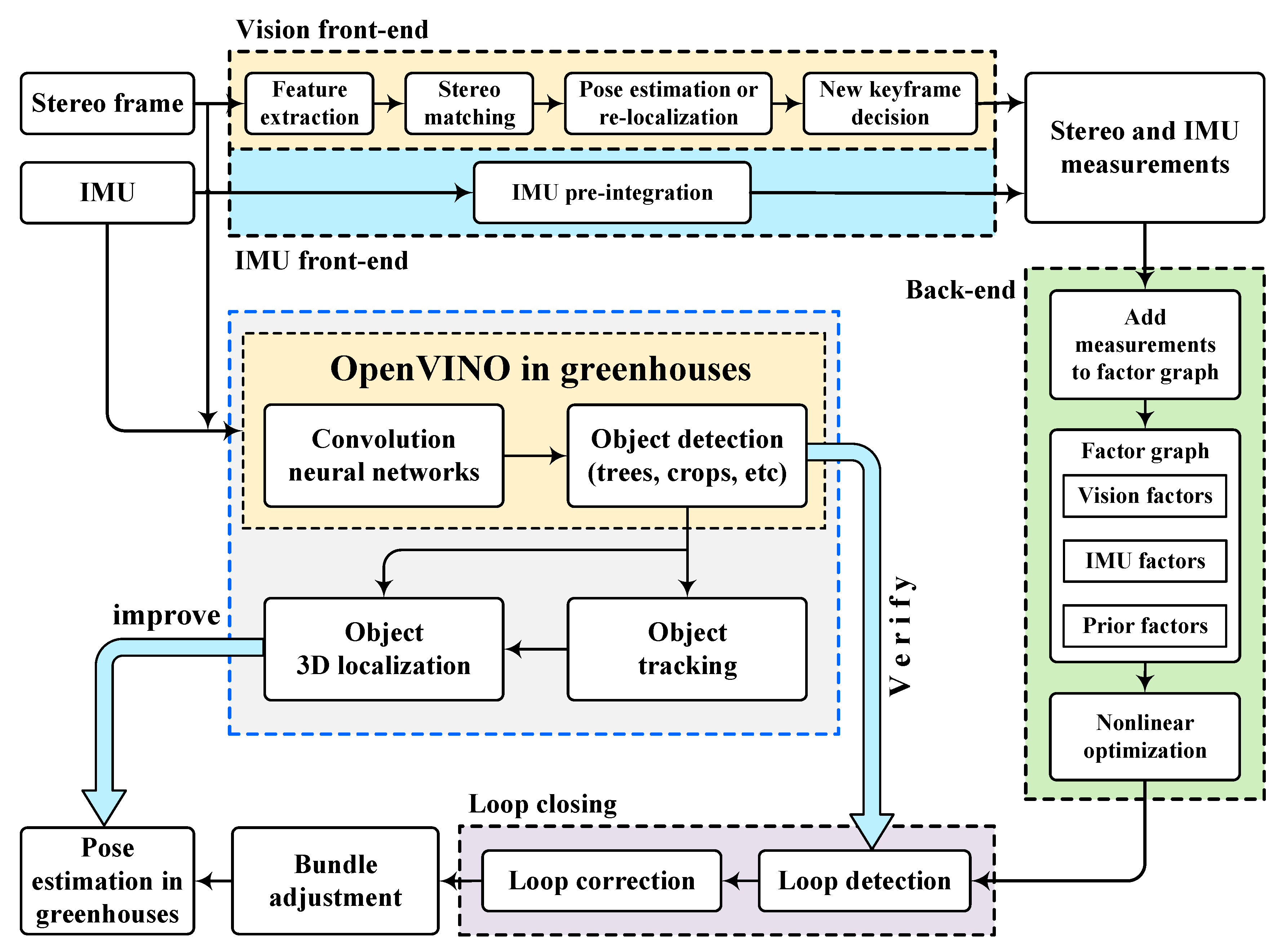
2.4. Visual–Inertial Tightly Coupled SLAM

To correct the state estimation of wheel odometry and IMU, the Intel Realsense tracking camera T265 is used in the visual–inertial SLAM (VI-SLAM) module to acquire the 6DOF pose estimation of the robot. Realsense T265 is a commercial device that advertises a highly accurate implementation of Visual–Inertial Odometry (VIO) in a single compact and low-power onboard processing unit [41]. In addition to an IMU, the T265 contains calibrated stereo fisheye cameras which provide accurate feature point tracking as well as scale correction [42]. The Intel Realsense Software Development Kit (SDK) 2.0 (https://github.com/IntelRealSense/librealsense, accessed on 28 June 2022) is installed to integrate the T265 streaming data into existing codebases and the ROS package realsense-ros (https://github.com/IntelRealSense/realsense-ros, accessed on 28 June 2022) is used to make the T265 usable under the ROS environment.
Like other visual–inertial SLAM algorithms, the VI-SLAM provided by T265 is mainly composed of four parts: vision front-end, IMU front-end, back-end optimization and loop closing. Feature extraction, feature matching and pose estimation of two consecutive camera frames are completed in the vision front-end as traditional visual SLAM algorithms. The pre-integration of IMU is calculated in the IMU front-end to acquire translation from the double integral of accelerometer and rotation from the integral of gyroscope. A factor graph containing both camera and IMU constraints is set up to minimize the pose estimation error in the back-end optimization part. The estimated trajectory is corrected in the loop closing part by checking whether the robot has revisited the previously visited area.
Unlike other visual–inertial SLAM algorithms, the VI-SLAM provided by T265 contains an Open Visual Inference and Neural Network Optimization (OpenVINO) module. OpenVINO is the Intel toolkit developed for odometry that employs convolution neural networks and data fusion with an IMU to improve the pose estimation. The OpenVINO also contains loop closure verification, allowing to correct the current pose estimation using previously visited locations [43].
Figure 3 shows the pose estimation process of the Intel RealSense tracking camera T265.

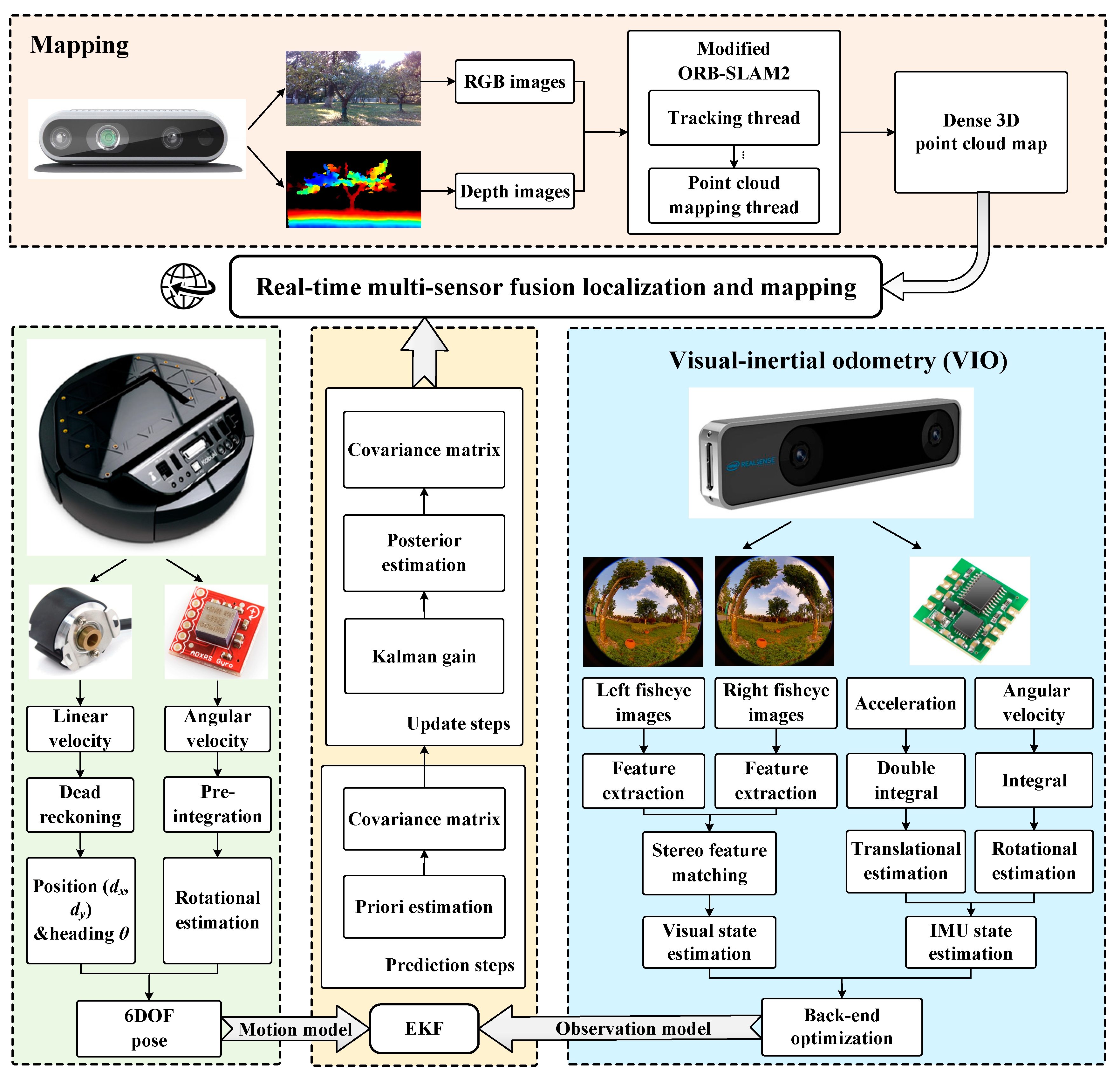
2.5. Visual–IMU–Wheel Odometry Fusion with EKF

A loosely coupled multi-sensor fusion framework based on EKF is used to fuse the pose estimations from wheel odometry, IMU and VIO for improved robustness and accuracy. As a treatment for the nonlinearity in the system, the EKF algorithm divides the system into a prediction step and an update step. The prediction step and update step are realized according to the motion model and observation model of the system.
The general definition of the motion model is
x k + 1 = f ( x k , u k + 1 ) + w k + 1
where xk+1 and xk represent the state variables at time k + 1 and k, respectively; uk+1 represents the control variables at time k + 1; f () represents the functional relation between xk+1 and xk; wk+1 represents the motion noise at the time k + 1, and the motion noise is assumed to be Gaussian white noise with a mean value of 0, as shown in Formulas (15) and (16).
w k + 1 ~ N ( 0 , Q k + 1 )
Q k + 1 = E [ w k + 1 w k + 1 T ]
The general definition of the observation model is
z k + 1 = h ( x k + 1 ) + v k + 1
where zk+1 represents the observation variables at time k + 1; h () represents the functional relation between xk+1 and zk+1; vk+1 represents the observation noise at the time k + 1, and the observation noise is assumed to be Gaussian white noise with a mean value of 0, as shown in Formulas (18) and (19).
v k + 1 ~ N ( 0 , R k + 1 )
R k + 1 = E [ v k + 1 v k + 1 T ]
Using the first-order Taylor expansion formula, the motion model is expanded into a linear equation
x k + 1 = f ( x ^ k , u k + 1 ) + f x ( x k x ^ k ) + w k + 1
where x ^ k represents the posterior estimation of the state vector at time k; fx represents the Jacobian matrix of the motion model.
Using the first-order Taylor expansion formula, the observation model is expanded into a linear equation
z k + 1 = h ( x ^ k + 1 ) + h x ( x k + 1 x ^ k + 1 ) + v k + 1
where x ^ k + 1 represents the priori estimation of the state vector at time k + 1; hx represents the Jacobian matrix of the observation model.
The working flow of the EKF algorithm is as follows:
Step 1 and Step 2 are the prediction steps and Steps 3 to 5 are the update steps.
Step 1: Predict the priori estimation of the state vector.
x ^ k + 1 = f ( x ^ k , u k + 1 )
Step 2: Predict the covariance matrix of the priori estimation of the state vector.
P k + 1 = f x P k f x T + Q k + 1
Step 3: Calculate the Kalman gain.
K k + 1 = P k + 1 h x T ( h x P k + 1 h x T + R k + 1 ) 1
Step 4: Acquire posterior estimation of the state variables by updating the state variables using the observation values.
x ^ k + 1 = x ^ k + 1 + K k + 1 ( z k + 1 h ( x ^ k + 1 ) )
Step 5: Update the covariance matrix to the covariance matrix of the posterior estimate of the state variable.
P k + 1 = ( I K k + 1 h x ) P k + 1
In Formula (26), I represents the identity matrix with the same dimension as the covariance matrix.
As can be seen from the working flow, the EKF algorithm can weigh the useful information in the observation zk+1h ( x ^ k + 1 ) by the Kalman gain Kk+1 to correct the priori estimation of the state vector. Therefore, in this study, we use the ROS node ekf_localization_node of the ROS package robot_localization (https://github.com/cra-ros-pkg/robot_localization, accessed on 28 June 2022) to achieve real-time multi-sensor fusion localization. The state estimations from wheel odometry and IMU are treated as predictions and the localization results from VI-SLAM are used as observations to update the state vector.

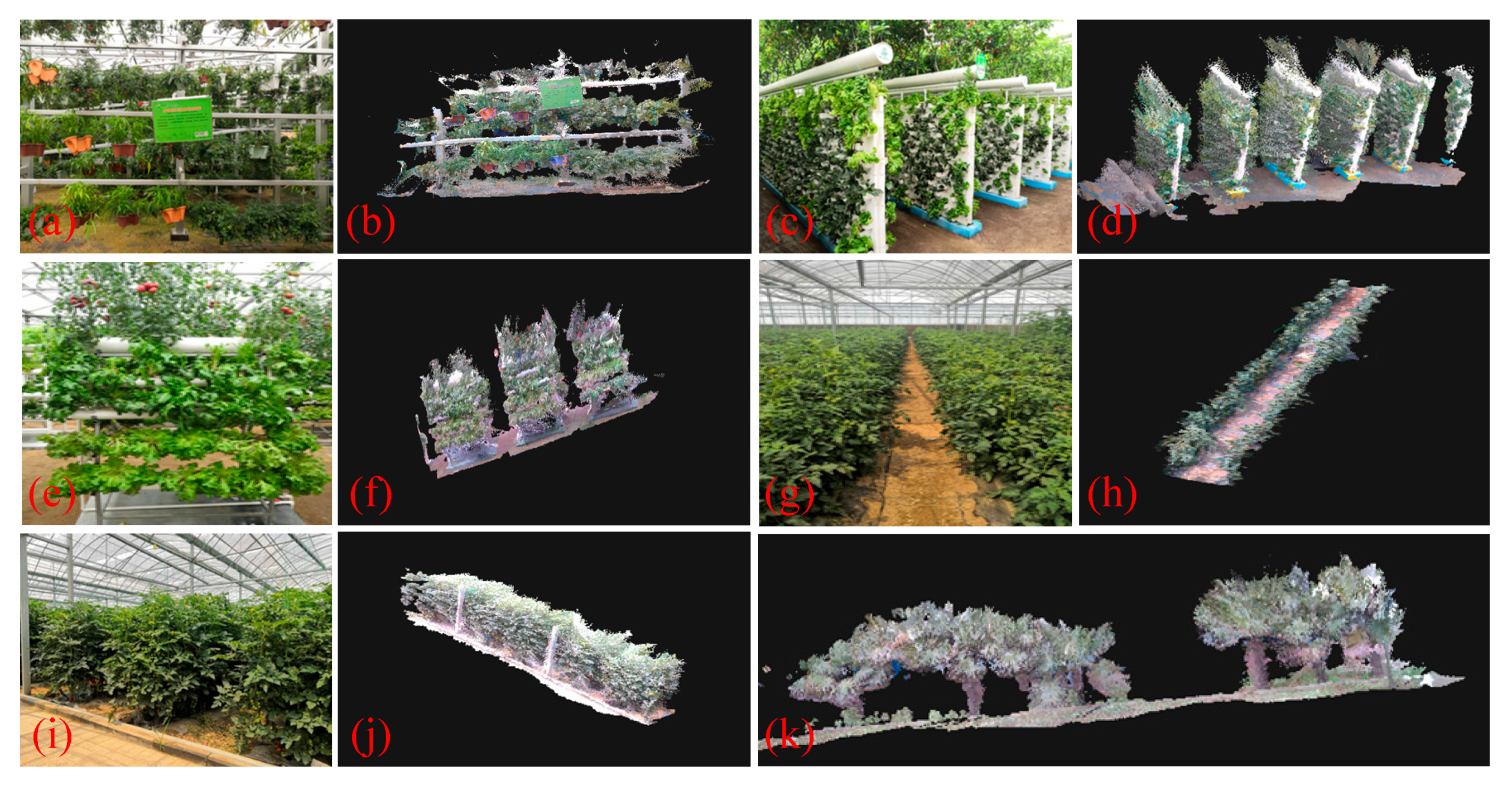
2.6. Dense 3D Point Cloud Mapping of Greenhouses

In the mapping module, we perform the modified ORB-SLAM2 (https://github.com/gaoxiang12/ORBSLAM2_with_pointcloud_map, accessed on 28 June 2022) algorithm to acquire the dense 3D point cloud map of the surroundings in real-time utilizing the Intel Realsense depth camera D435i. ORB-SLAM2 is a complete SLAM system for monocular, stereo and RGB-D cameras, including map reuse, loop closing and re-localization capabilities. The system works in real-time on standard CPUs in a wide variety of environments [44]. A sparse point cloud map can be generated directly using the algorithm. To acquire the dense point cloud map, we use the modified ORB-SLAM2 algorithm that adds a point cloud mapping thread to the framework of ORB-SLAM2. In the point cloud mapping thread, RGB and depth images obtained by Realsense D435i and pose estimations from the tracking thread are set as the input, and a dense 3D point cloud map can be generated and maintained. The dense 3D point cloud map can provide the robot with a more detailed representation of the surroundings. Therefore, by using the dense 3D point cloud map of greenhouses and the multi-sensor fusion localization results, the agricultural robots can realize re-localization when they fail to localize or are moved to another place artificially, resulting in the failure of localization, and achieving accurate path planning and obstacle avoidance in autonomous navigation tasks.

2.7. The Overall Localization and Mapping Framework

The proposed system mainly includes two parts: the multi-sensor fusion localization and the dense 3D point cloud mapping parts. The multi-sensor fusion localization part integrates the pose estimations from wheel odometry, an inertial measurement unit and a visual–inertial odometer. The wheel odometry of Turtlebot2 can provide both the position and heading of the mobile robot by using the dead reckoning method, and the angular velocity offered by the three-axis gyroscope of the chassis Kobuki can be pre-integrated to estimate the rotational motion. By combing the estimations from the wheel odometry and IMU, the 6DOF pose of the robot can be obtained and is set as the motion model of prediction steps of the EKF. To correct the pose estimations in the prediction process, the Intel Realsense tracking camera T265 is used as visual–inertial odometry (VIO) to update the measurements from the prediction steps. The VIO fuses information from multiple fisheye imagers with sensor readings from an IMU in a tightly coupled way and tracks the 6DoF pose in real-time. The pose estimations of the VIO are set as the observation model of the EKF to correct the predicted results, and the filtered trajectory is relatively accurate. In the dense 3D point cloud mapping part, the modified ORB-SLAM2 algorithm is utilized to generate a dense 3D point cloud map of surroundings on a standard CPU in real-time. The specific flowchart of the system is shown in Figure 4.

3. Results and Discussion

The experiments were conducted in Shouguang City, Weifang City, Shandong Province, China. The greenhouses were modern standard solar greenhouses in the Modern agricultural high and new technology experiment and demonstration base and Shouguang vegetable high-tech demonstration park, suitable for carrying out localization, mapping and navigation experiments with agricultural robots. The types of crops in the greenhouses were varied and all were in a state of vigorous growth. In the experiments, the motion of the mobile robot was controlled by the commands from the laptop, and the localization and mapping tasks were completed in real-time while the robot was moving in the greenhouses.

3.1. Evaluation of Localization Accuracy

To demonstrate the effectiveness of the proposed multi-sensor fusion localization method, we carried out six experimental tests. Four of the tests were conducted in the greenhouses. Two tests were conducted in an outdoor campus environment to verify the feasibility of the proposed method in different settings. Each test contained complex environmental conditions, bringing challenges for the robot to achieve accurate localization. Figure 5 shows the experimental environments of each test. The localization accuracy evaluation tool of our proposed method is EVO (https://github.com/MichaelGrupp/evo, accessed on 28 June 2022) and the evaluation index is the absolute pose error (APE) values considering both rotation and translation errors (unitless: the unit of translation APE is the meter and the rotation APE has no unit, so the full APE is unitless), compared to the ground truth. The APE is a metric for investigating the global consistency of a SLAM trajectory. APE is based on the absolute relative pose between two poses Pref,i, Pest,i ∈ SE(3) at timestamp i
E i = P e s t , i P r e f , i = P r e f , i 1 P e s t , i SE ( 3 )
where ⊖ is the inverse compositional operator which takes two poses and gives the relative pose.
In APE, the translation error is calculated by using the translation part of Ei and the rotation error is calculated by using the rotation part of Ei.
A P E t r a n s , i = trans ( E i )
A P E r o t , i = rot ( E i ) I 3 × 3 F
The full error considering both rotation and translation errors is calculated by using full Ei.
A P E i = E i I 4 × 4 F
Since the rotation error uses the F-norm of the matrix, the rotation error is unitless, so the total error is also unitless. Figure 6 depicts the APE of tests 1 to 4.
In EVO, evo_res is a tool for comparing one or multiple result files from evo_ape, i.e., evo_res is an APE comparison tool. Therefore, RES is used for APE value comparisons. Figure 7 shows RES of tests 1 to 4 between our method and the VIO from the Realsense T265. The quantitative results comparisons are reported in Table 1.

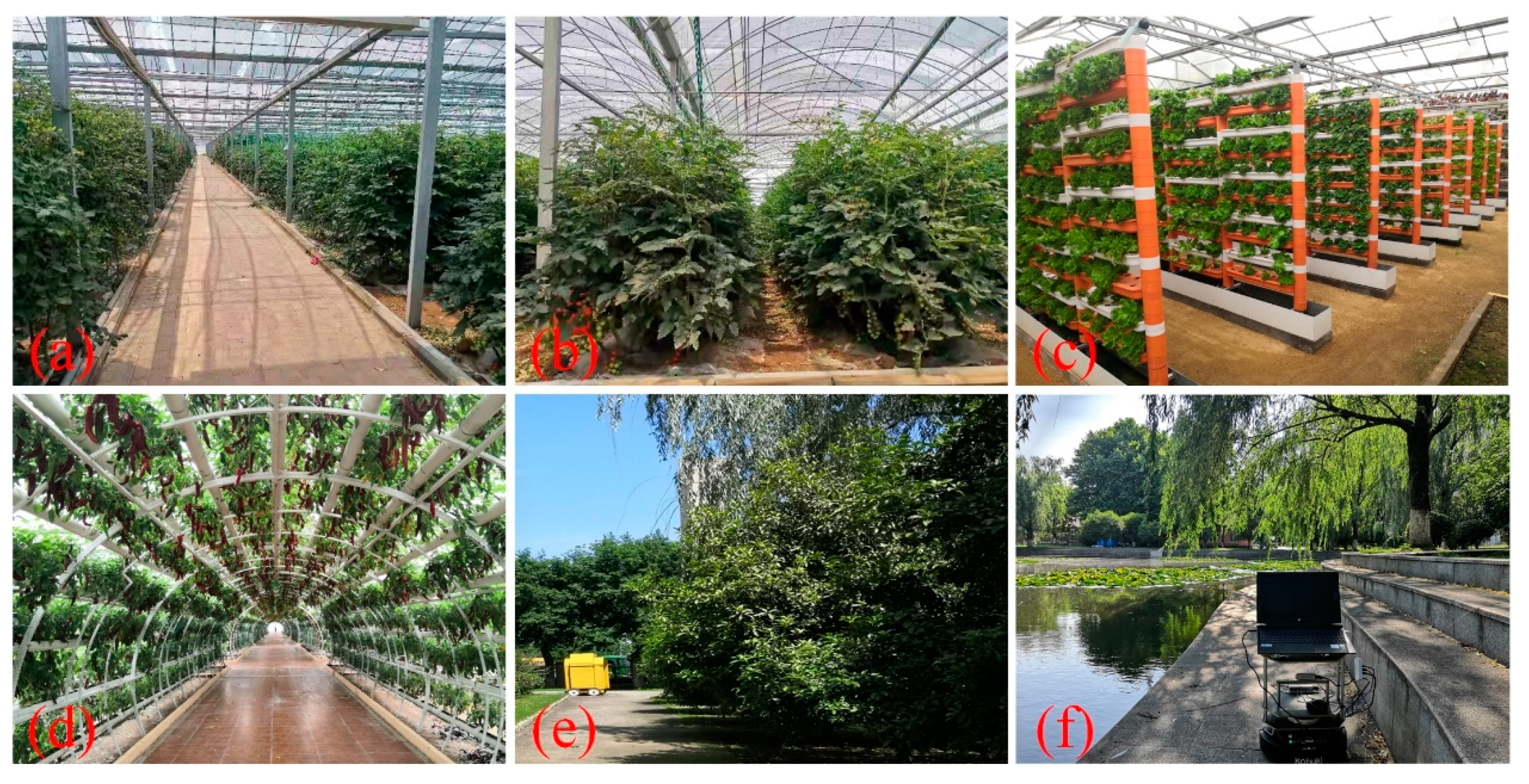
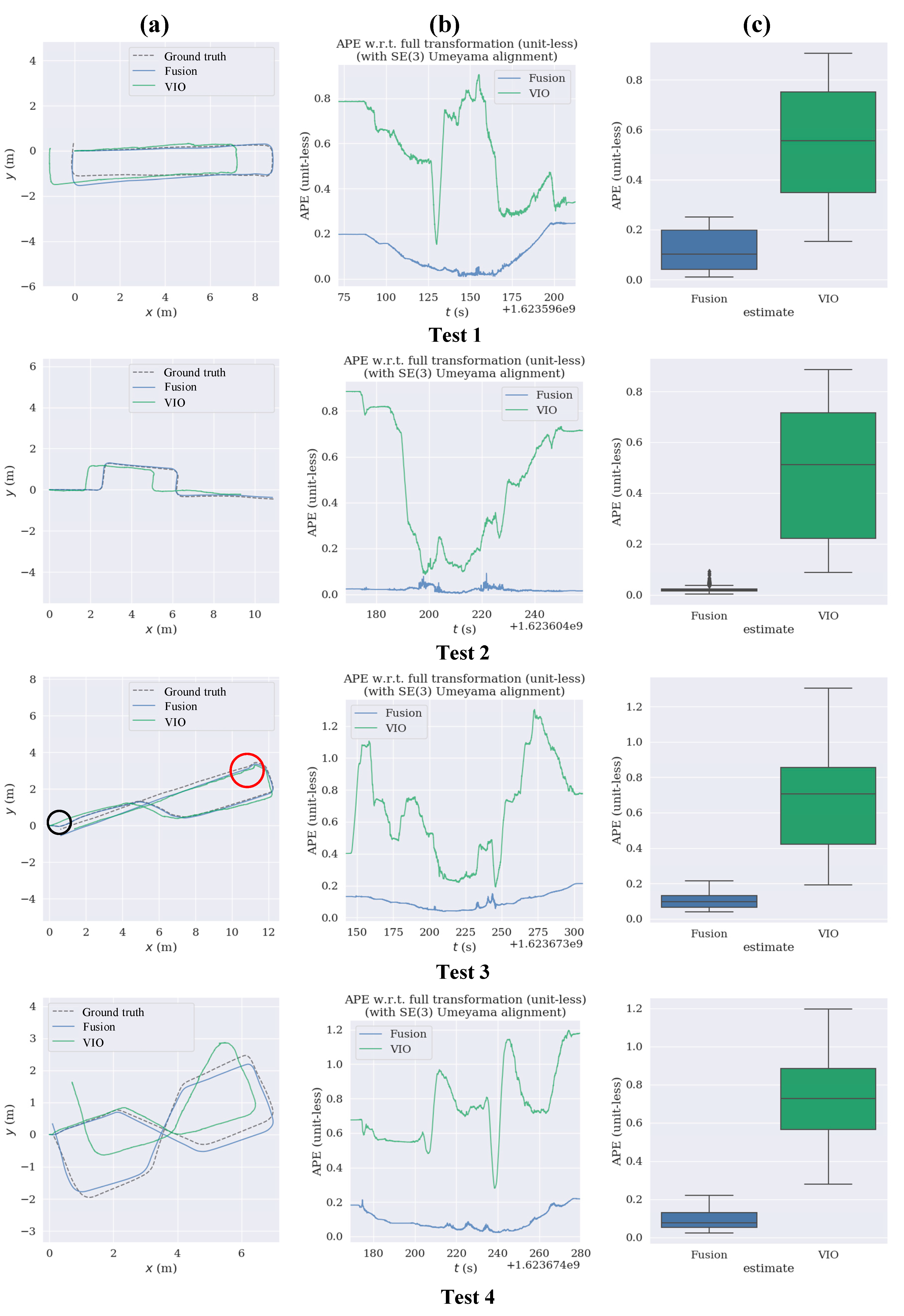
3.1.1. Traveling a Closed Path inside a Greenhouse

In test 1, the mobile robot traveled a loop path inside a greenhouse. The track was under harsh environmental conditions, including intense sunlight, repeated scenes and dynamically changing crops, as shown in Figure 5a. Algorithms of wheel odometry, IMU, visual–inertial odometry and the proposed Visual–IMU–Wheel odometry were executed online to estimate the robot’s pose. It can be seen from column (c) of test1 in Figure 6 that the overall performance of the VIO estimation results in this test is relatively accurate, so the VIO is a good choice as the observation model of the EKF.
However, the localization error of the VIO suddenly becomes large when the robot turns right angles to return to the origin. Thus, the trajectory estimated by the VIO does not form a loop path and the loop error is about 1 m. In stark contrast, the trajectory estimated by our approach is exact, with the max absolute pose error (APE) of 0.25, and the loop error of our method is approximately equal to zero, reaching a perfect loop closing effect in the greenhouse environment, due to the fusion of the wheel odometry, IMU and VIO. In addition, each error evaluation index caused by our method is lower than the error value of the VIO, demonstrating the effectiveness of the proposed method in such a loop path test, as shown in the first and second rows of Table 1.

3.1.2. Crossing the Intersection in the Greenhouse

For agricultural robots, it is a highly crucial ability to achieve a turn between crop rows in a large facility greenhouse environment. The accuracy of the turns has a direct influence on the effectiveness of autonomous operations. Therefore, in test 2, we evaluated the validity of the multi-sensor fusion localization method by having the robot cross the intersections in the greenhouse. The scenario of this test is shown in Figure 5b.
As shown visually from column (a) of test 2 in Figure 7, the trajectory estimated by our proposed method almost coincides with the ground truth trajectory. In contrast, the trajectory singly calculated by the VIO has a translational estimation error since the first turn of the test. In addition, the absolute pose error of our method throughout the test is close to zero and noise error appears only slightly, as shown in column (b) of test 2 in Figure 7. However, the APE from the VIO is relatively giant at the beginning and end of the test, and there is much noise error during the middle time of the experiment, compared to our method. Although the Root Mean Square Error (RMSE) and max error of the VIO are 0.564 and 0.89, respectively, seeming not so large, the RMSE and max error of the proposed localization method are only 0.023 and 0.09, respectively, approaching zero, as can be seen from the third and fourth rows of Table 1. Therefore, our method can provide the robot with a more accurate localization result when the robot crosses the intersections in greenhouses to benefit autonomous navigation for agricultural robots.

3.1.3. Traveling in a Soilless Greenhouse

Soilless culture has been widely used in agriculture in recent years, so it is of great significance for robots to realize accurate localization in these environments. In test 3, the robot traveled through an area of a soilless greenhouse under the control of motion commands from the laptop to verify the applicability of the proposed localization method in soilless greenhouses. Figure 5c shows an area of the soilless greenhouse used for this test.
In this test, the robot started with a slight change in direction, as marked by the black circle in column (a) of test 3 in Figure 7. Our method accurately estimates the subtle shift in direction; however, the VIO fails to precisely perceive this small change and the estimated trajectory is a straight line. The track also contains multiple turns. We can see from the result that the trajectory calculated by the VIO is not smooth after the turns, especially after the second quarter turn, as marked by the red circle. However, the trajectory estimated by our method is smooth throughout. In addition, the max error of the VIO is 1.304, while the max error of our strategy is 0.214, almost equal to the minimum error of the VIO, as shown in the fifth and sixth rows of Table 1. Therefore, the VIO is not accurate enough due to the high complexity of the soilless greenhouse and our method can achieve a reasonable accuracy in such an environment.

3.1.4. Moving through the Gallery Frame Structure in the Greenhouse

The gallery frame structure is widely used in greenhouses and agricultural environments. It brings significant challenges to robot localization due to the long, narrow, and highly repetitive gallery frame structure. To evaluate the localization effect of our method in these environments, in test 4, we designed an ‘8′-shaped trajectory for the robot to move through the gallery frame structure in the greenhouse. The test scenario is shown in Figure 5d.
As can be seen from group test 4 in Figure 6, the overall localization accuracy of the VIO is not ideal, causing apparent trajectory drift. The error of the VIO indicates that the visual approach is not well suited to this type of environment, even with the tight coupling of IMU, because of the large number of mismatches when there are repetitive features such as the frames in the long and narrow gallery. However, our approach dramatically improves the localization precision by using the measurements from wheel odometry and a three-axis gyroscope as the prediction of the EKF. The RMSE of our method is only 0.109. In comparison, the RMSE of the VIO is about 0.782, being a significant error for the robot to navigate in the narrow gallery frame structure environments. Therefore, the proposed localization method successfully makes up for the deficiency and misestimation of visual sensors in such a complex gallery frame structure environment.

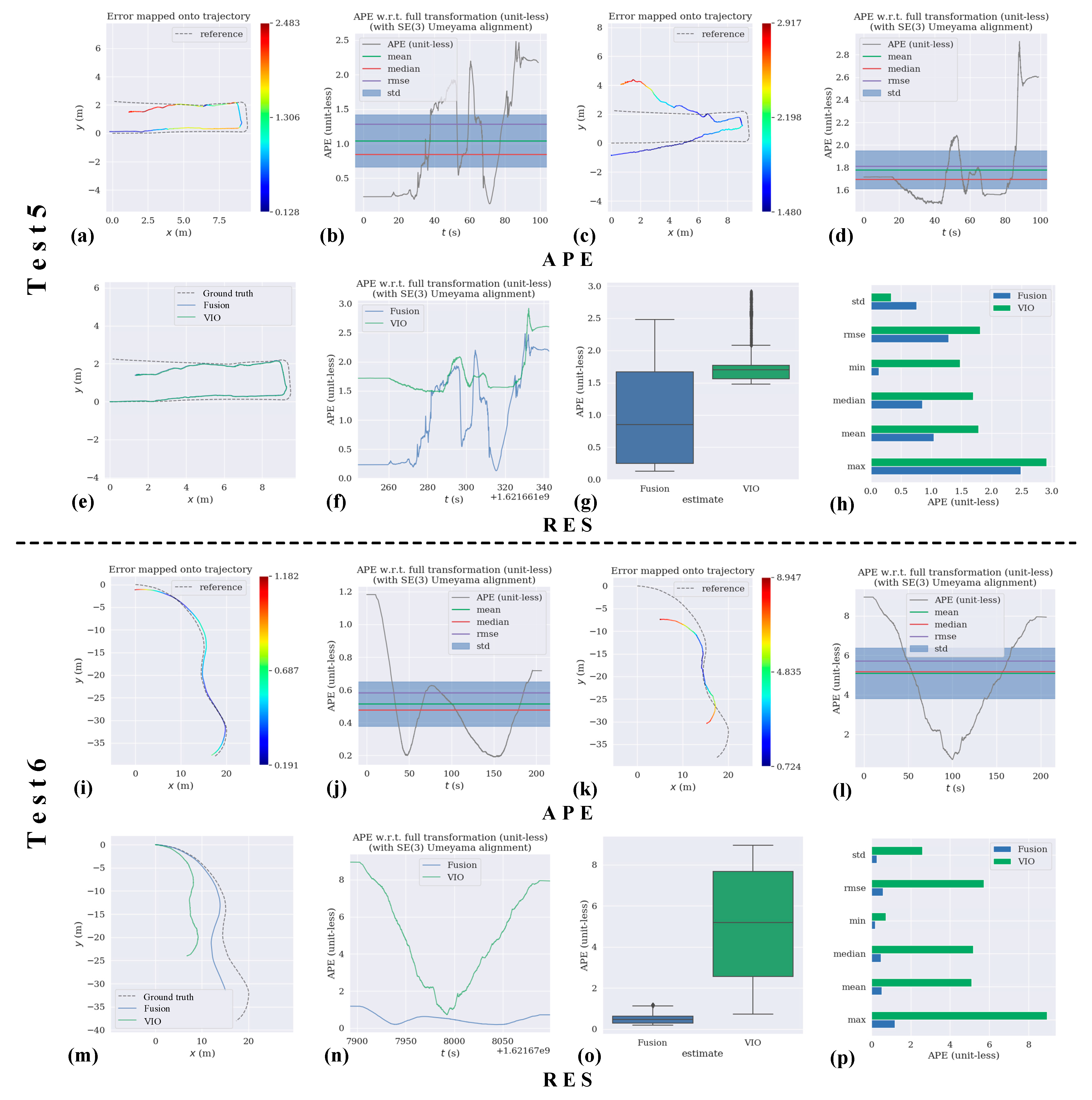
3.1.5. Moving in the Long Straight Grove

Our proposed method has relatively high localization accuracy in various greenhouse environments, as can be concluded from tests 1 to 4. To evaluate the positioning ability of our approach in other settings, we carried out two tests in the outdoor campus environment. Figure 8 shows the APE and RES of tests 5 and 6. In test 5, the robot traveled a path similar to test 1 in a long straight grove on campus, but there was no loop. Figure 5e shows the long straight grove with the intense sunlight.
Unlike test 1, the localization accuracy of the VIO is weak and the estimated trajectory differs significantly from the ground truth, as shown in Figure 8c, due to the intense light affecting the visual estimation. However, the trajectory calculated by our method achieves relatively high accuracy with the RMSE is 0.607. Although there is an offset error at the tail of the trajectory estimated by our approach because of the direct sunlight, the estimation is generally reliable. Therefore, the measurements of wheel odometry and gyroscope efficiently improve the localization accuracy of the VIO, and our proposed method is more suitable for localizing robots in such a harsh environment.

3.1.6. Touring at the Edge of the Pond

In test 6, the mobile robot traveled at the edge of the pond on the campus, as shown in Figure 5f. The road around the pond is curved, with a pool reflecting light on one side and trees on the other, bringing many challenges for robots to achieve precise localization.
As can be seen from Figure 8k, the estimated trajectory of the VIO has the same shape as the ground truth. However, there are a certain number of estimation failures of the VIO in this test, especially the scale estimation errors. The reasons for this problem include the lack of sufficient feature points when the camera is in the reflective area and the large number of mismatches when there are repetitive and dynamic features such as the wicker flapping in the wind. In contrast, aided by the wheel odometry and gyroscope, not only the scale problem is eliminated, but also the localization accuracy was remarkably improved, as shown in the eleventh and twelfth rows of Table 1. The RMSE drops from 5.714 to 0.583, reaching an ideal result in an open outdoor area. In consequence, the multi-sensor fusion method can make up for the defects of each sensor to achieve relatively accurate localization in complex environments.

3.2. Analysis of Localization Robustness

In the experiment, we carried out robot localization tests in a variety of complex scenarios, as can be seen from Section 3.1. The experimental environments are all highly unstructured and crops are in dynamic growth and change. Moreover, the sunlight is intense and the GPS is ineffective. All these factors make the localization extremely challenging: (1) The unstructured characteristics significantly reduce the stable geometric features for the visual SLAM, especially in test 6; (2) The dynamics of the environments cause outliers to the visual features; (3) The highly repeated visual features of the leaves cause the error in matching and tracking the features in visual SLAM; (4) Intense illumination seriously affects the robustness of the visual estimation method.
Despite these challenges, our localization approach is robust enough to survive in these scenes. The results show that our method can achieve accurate localization under various challenges and even endure the severe estimation error of the visual algorithm. The results demonstrate that our localization strategy is of high robustness and accuracy.

3.3. Mapping Quality

Localization and mapping are essential abilities for robots to realize autonomous navigation. Using the dense 3D point cloud map in the navigation tasks can provide the robot with a more detailed representation of the surroundings. Therefore, the robot can achieve safer and more accurate autonomous navigation. In order to verify the availability of the dense 3D mapping method, a series of experiments were conducted in complex greenhouse environments. The results are shown in Figure 9.
Experiments 1 to 3 were carried out in a soilless greenhouse. The soilless greenhouse has various kinds of spatial cultivation structures. We choose orbital cultivation, wall cultivation and stereoscopic cultivation sites to generate dense 3D maps. Figure 9a,b show the scene and dense 3D map of the orbital cultivation site. Figure 9c,d represent the experiment of the wall cultivation site. Figure 9e,f represent the experiment of the stereoscopic cultivation site. The three kinds of spatial cultivation structures have extremely complex characteristics, bringing challenges to the dense mapping task. The experimental results show that the dense 3D point cloud maps are well displayed and the real-time dense mapping algorithm is effective. Both unstructured crops and structured shelves are well constructed into dense point cloud maps. However, the maps are still not perfect. There are some holes and gaps in the maps because some places are not scanned by the RGB-D camera.
Experiments 4 and 5 are carried out in a greenhouse with intense sunlight. The scene of experiment 4 is a crop inter-row, as shown in Figure 9g,h. The row and crops are effectively mapped; even the weeds are reconstructed. Therefore, the dense mapping method is suitable for such an environment and can be employed for obstacle avoidance and autonomous navigation. In experiment 5, a dense 3D point cloud map of the periphery of crop rows is constructed, as shown in Figure 9i,j. The crops and shelves in this scene are successfully mapped and the spatial structure of the environment is clear and distinct on the map. However, the map is still not perfect. The crops are slightly indistinct due to the influence of intense sunlight.
To verify the broad applicability of the dense mapping method, we conducted experiment 6 in an outdoor forest. The mapping result is shown in Figure 9k. From the result, the trunks, leaves and lawn are all constructed into a dense 3D point cloud map effectively, so the method is suitable for large-scale and unstructured 3D mapping. However, some specific details of the trees are unclear on the map. The reasons for this problem are: (1) Some leaves were sheltered by other chaff interferents or not in the range of the RGB-D camera; (2) This experiment was carried out outdoors, therefore the mapping quality was influenced by the sunlight; (3) The scanning speed of the camera was a little fast. In the mapping experiments, the results show the accuracy and robustness of the dense 3D mapping method for unstructured, dynamic and large-scale greenhouse environments.

4. Conclusions

In this paper, a novel real-time localization and mapping method is proposed for unstructured, dynamic and GPS-denied greenhouse environments. To achieve accurate and robust pose estimation of the robot in complex greenhouses, the proposed method integrates measurements from wheel odometry, an inertial measurement unit and visual–inertial odometry into a loosely coupled multi-sensor fusion framework based on the Extended Kalman Filter to make up for the defects of a single sensor. The dense 3D point cloud map of the surroundings is generated using the modified ORB-SLAM2 algorithm simultaneously as localization. By combining the result of accurate localization and dense 3D point cloud map, agricultural robots can realize more precise re-localization and provide the basis for further autonomous navigation.
The method is evaluated in modern standard solar greenhouses and an outdoor campus environment with various complex environmental conditions. In all the tests, our method achieves a high level of accuracy and robustness in localization and mapping. However, in the outdoor environment, since the visual part is greatly affected by light, the accuracy of the multi-sensor fusion localization and mapping system is reduced to a certain extent, and the effect is not as good as in the greenhouse. Moreover, this study does not go deep into combining localization and mapping results for autonomous navigation. Therefore, for future work, the multi-sensor fusion localization framework may involve other sensors to adapt to more severe environments and the results of localization and mapping will be better combined to achieve autonomous navigation in complex agricultural environments.

Author Contributions

Conceptualization, Y.Y. and B.Z.; methodology, Y.Y. and B.Z.; software, Y.Y.; validation, Y.Y., Y.Z. and X.L.; formal analysis, Y.Y., Y.Z. and X.L.; investigation, Y.Y. and B.Z.; resources, B.Z. and J.Z.; data curation, B.Z.; writing—original draft preparation, Y.Y.; writing—review and editing, Y.Y.; visualization, Y.Y. and B.Z.; supervision, B.Z. and J.Z.; project administration, B.Z. and J.Z.; funding acquisition, B.Z. All authors have read and agreed to the published version of the manuscript.

Funding

This work was funded by the National Natural Science Foundation of China (Project no. 31901415), and the Jiangsu Agricultural Science and Technology Innovation Fund (JASTIF) (Grant no. CX (21)3146).

Data Availability Statement

Data are available on request from the corresponding author.

Conflicts of Interest

The authors declare no conflict of interest.

References

  1. Shalal, N.; Low, T.; McCarthy, C.; Hancock, N. Orchard mapping and mobile robot localisation using on-board camera and laser scanner data fusion–Part B: Mapping and localisation. Comput. Electron. Agric. 2015, 119, 267–278. [Google Scholar] [CrossRef]
  2. Erfani, S.; Jafari, A.; Hajiahmad, A. Comparison of two data fusion methods for localization of wheeled mobile robot in farm conditions. Artif. Intell. Agric. 2019, 1, 48–55. [Google Scholar] [CrossRef]
  3. Winterhalter, W.; Fleckenstein, F.; Dornhege, C.; Burgard, W. Localization for precision navigation in agricultural fields—Beyond crop row following. J. Field Robot. 2021, 38, 429–451. [Google Scholar] [CrossRef]
  4. Zhang, B.; Xie, Y.; Zhou, J.; Wang, K.; Zhang, Z. State-of-the-art robotic grippers, grasping and control strategies, as well as their applications in agricultural robots: A review. Comput. Electron. Agric. 2020, 177, 105694. [Google Scholar] [CrossRef]
  5. Chewu, C.C.E.; Kumar, V.M. Autonomous navigation of a mobile robot in dynamic indoor environments using SLAM and reinforcement learning. In Proceedings of the IOP Conference Series: Materials Science and Engineering, Nanjing, China, 17–19 August 2018; IOP Publishing: Bristol, UK, 2018; Volume 402, p. 012022. [Google Scholar] [CrossRef]
  6. Kalogeiton, V.S.; Ioannidis, K.; Sirakoulis, G.C.; Kosmatopoulos, E.B. Real-Time Active SLAM and Obstacle Avoidance for an Autonomous Robot Based on Stereo Vision. Cybern. Syst. 2019, 50, 239–260. [Google Scholar] [CrossRef]
  7. Plessen, M.G. Coupling of crop assignment and vehicle routing for harvest planning in agriculture. Artif. Intell. Agric. 2019, 2, 99–109. [Google Scholar] [CrossRef]
  8. Chen, Y.; Zhang, B.; Zhou, J.; Wang, K. Real-time 3D unstructured environment reconstruction utilizing VR and Kinect-based immersive teleoperation for agricultural field robots. Comput. Electron. Agric. 2020, 175, 105579. [Google Scholar] [CrossRef]
  9. Xiong, Y.; Ge, Y.; Grimstad, L.; From, P.J. An autonomous strawberry-harvesting robot: Design, development, integration, and field evaluation. J. Field Robot. 2020, 37, 202–224. [Google Scholar] [CrossRef] [Green Version]
  10. Balasuriya, B.L.E.A.; Chathuranga, B.A.H.; Jayasundara, B.H.M.D.; Napagoda, N.R.A.C.; Kumarawadu, S.P.; Chandima, D.P.; Jayasekara, A.G.B.P. Outdoor robot navigation using Gmapping based SLAM algorithm. In Proceedings of the 2016 Moratuwa Engi-neering Research Conference (MERCon), Moratuwa, Sri Lanka, 5–6 April 2016; pp. 403–408. [Google Scholar] [CrossRef]
  11. Yousif, K.; Bab-Hadiashar, A.; Hoseinnezhad, R. An Overview to Visual Odometry and Visual SLAM: Applications to Mobile Robotics. Intell. Ind. Syst. 2015, 1, 289–311. [Google Scholar] [CrossRef]
  12. Yang, S.; Scherer, S. Monocular Object and Plane SLAM in Structured Environments. IEEE Robot. Autom. Lett. 2019, 4, 3145–3152. [Google Scholar] [CrossRef] [Green Version]
  13. Droeschel, D.; Behnke, S. Efficient Continuous-time SLAM for 3D Lidar-based Online Mapping. In Proceedings of the 2018 IEEE International Conference on Robotics and Automation (ICRA), Brisbane, Australia, 21–25 May 2018; pp. 5000–5007. [Google Scholar] [CrossRef] [Green Version]
  14. Ding, H.; Zhang, B.; Zhou, J.; Yan, Y.; Tian, G.; Gu, B. Recent developments and applications of simultaneous localization and mapping in agriculture. J. Field Robot. 2022, 1–28. [Google Scholar] [CrossRef]
  15. Deng, X.; Zhang, Z.; Sintov, A.; Huang, J.; Bretl, T. Feature-constrained active visual SLAM for mobile robot navigation. In Proceedings of the 2018 IEEE International Conference on Robotics and Automation (ICRA), Brisbane, Australia, 21–25 May 2018; pp. 7233–7238. [Google Scholar] [CrossRef]
  16. Wang, S.; Wu, Z.; Zhang, W. An overview of SLAM. In Proceedings of the 2018 Chinese Intelligent Systems Conference; Springer: Singapore, 2019; pp. 673–681. [Google Scholar] [CrossRef]
  17. Wang, S.; Li, Y.; Sun, Y.; Li, X.; Sun, N.; Zhang, X.; Yu, N. A localization and navigation method with ORB-SLAM for indoor service mobile robots. In Proceedings of the 2016 IEEE International Conference on Real-Time Computing and Robotics (RCAR), Angkor Wat, Cambodia, 6–10 June 2016; pp. 443–447. [Google Scholar] [CrossRef]
  18. Filipenko, M.; Afanasyev, I. Comparison of various slam systems for mobile robot in an indoor environment. In Proceedings of the 2018 International Conference on Intelligent Systems (IS), Funchal, Portugal, 25–27 September 2018; pp. 400–407. [Google Scholar] [CrossRef]
  19. Xu, L.; Feng, C.; Kamat, V.R.; Menassa, C.C. An Occupancy Grid Mapping enhanced visual SLAM for real-time locating applications in indoor GPS-denied environments. Autom. Constr. 2019, 104, 230–245. [Google Scholar] [CrossRef]
  20. Fang, B.; Mei, G.; Yuan, X.; Wang, L.; Wang, Z.; Wang, J. Visual SLAM for robot navigation in healthcare facility. Pattern Recognit. 2021, 113, 107822. [Google Scholar] [CrossRef]
  21. Yang, Y.; Tang, D.; Wang, D.; Song, W.; Wang, J.; Fu, M. Multi-camera visual SLAM for off-road navigation. Robot. Auton. Syst. 2020, 128, 103505. [Google Scholar] [CrossRef]
  22. Afia, A.B.; Escher, A.C.; Macabiau, C. A low-cost gnss/imu/visual monoslam/wss integration based on federated kalman filtering for navigation in urban environments. In Proceedings of the 28th International Technical Meeting of the Satellite Division of The Institute of Navigation (ION GNSS+ 2015), Tampa, FL, USA, 14–18 September 2015; pp. 618–628. [Google Scholar]
  23. Alliez, P.; Bonardi, F.; Bouchafa, S.; Didier, J.-Y.; Hadj-Abdelkader, H.; Munoz, F.I.; Kachurka, V.; Rault, B.; Robin, M.; Roussel, D. Real-Time Multi-SLAM System for Agent Localization and 3D Mapping in Dynamic Scenarios. In Proceedings of the 2020 IEEE/RSJ International Conference on Intelligent Robots and Systems (IROS), Las Vegas, NV, USA, 24–30 October 2020; pp. 4894–4900. [Google Scholar] [CrossRef]
  24. Lin, J.; Zheng, C.; Xu, W.; Zhang, F. R2LIVE: A Robust, Real-time, LiDAR-Inertial-Visual tightly-coupled state Estimator and mapping. arXiv 2021, arXiv:2102.12400. [Google Scholar]
  25. Dong, W.; Roy, P.; Isler, V. Semantic mapping for orchard environments by merging two-sides reconstructions of tree rows. J. Field Robot. 2020, 37, 97–121. [Google Scholar] [CrossRef]
  26. Post, M.A.; Bianco, A.; Yan, X.T. Autonomous navigation with ROS for a mobile robot in agricultural fields. In Proceedings of the 14th International Conference on Informatics in Control, Automation and Robotics (ICINCO), Madrid, Spain, 26–28 July 2017. [Google Scholar] [CrossRef]
  27. Galati, R.; Reina, G.; Messina, A.; Gentile, A. Survey and navigation in agricultural environments using robotic technologies. In Proceedings of the 2017 14th IEEE International Conference on Advanced Video and Signal Based Surveillance (AVSS), Lecce, Italy, 29 August–1 September 2017; pp. 1–6. [Google Scholar] [CrossRef]
  28. Astolfi, P.; Gabrielli, A.; Bascetta, L.; Matteucci, M. Vineyard Autonomous Navigation in the Echord++ GRAPE Experiment. IFAC-PapersOnLine 2018, 51, 704–709. [Google Scholar] [CrossRef]
  29. Ali, W.; Sheng, L.; Ahmed, W. Robot Operating System-Based SLAM for a Gazebo-Simulated Turtlebot2 in 2d Indoor Environment with Cartographer Algorithm. Int. J. Mech. Mechatron. Eng. 2021, 15, 149–157. [Google Scholar]
  30. Alag, G. Evaluating the Performance of Intel Realsense T265 Xsens Technologies BV. 2020. Available online: https://purl.utwente.nl/essays/86344 (accessed on 28 June 2022).
  31. Argush, G.; Holincheck, W.; Krynitsky, J.; McGuire, B.; Scott, D.; Tolleson, C.; Behl, M. Explorer51–Indoor Mapping, Discovery, and Navigation for an Autonomous Mobile Robot. In Proceedings of the 2020 Systems and Information Engineering Design Symposium (SIEDS), Charlottesville, VA, USA, 24 April 2020; pp. 1–5. [Google Scholar] [CrossRef]
  32. Chien, W.Y. Stereo-Camera Occupancy Grid Mapping. Master′s Thesis, The Pennsylvania State University, State College, PA, USA, 2020. [Google Scholar]
  33. Myint, C.; Win, N.N. Position and velocity control for two-wheel differential drive mobile robot. Int. J. Sci. Eng. Technol. Res. 2016, 5, 2849–2855. [Google Scholar]
  34. Shafaei, S.M.; Loghavi, M.; Kamgar, S. Benchmark of an intelligent fuzzy calculator for admissible estimation of drawbar pull supplied by mechanical front wheel drive tractor. Artif. Intell. Agric. 2020, 4, 209–218. [Google Scholar] [CrossRef]
  35. Zhu, J.; Tang, Y.; Shao, X.; Xie, Y. Multisensor Fusion Using Fuzzy Inference System for a Visual-IMU-Wheel Odometry. IEEE Trans. Instrum. Meas. 2021, 70, 2505216. [Google Scholar] [CrossRef]
  36. Brunetto, N.; Salti, S.; Fioraio, N.; Cavallari, T.; Stefano, L. Fusion of inertial and visual measurements for rgb-d slam on mobile devices. In Proceedings of the IEEE International Conference on Computer Vision Workshops, Santiago, Chile, 7–13 December 2015; pp. 1–9. [Google Scholar] [CrossRef]
  37. Qin, T.; Li, P.; Shen, S. VINS-Mono: A Robust and Versatile Monocular Visual-Inertial State Estimator. IEEE Trans. Robot. 2018, 34, 1004–1020. [Google Scholar] [CrossRef] [Green Version]
  38. Bloesch, M.; Omari, S.; Hutter, M.; Siegwart, R. Robust visual inertial odometry using a direct EKF-based ap-proach. In Proceedings of the 2015 IEEE/RSJ International Conference on Intelligent Robots and Systems (IROS), Hamburg, Germany, 28 September–3 October 2015; pp. 298–304. [Google Scholar] [CrossRef] [Green Version]
  39. Forster, C.; Carlone, L.; Dellaert, F.; Scaramuzza, D. On-Manifold Preintegration for Real-Time Visual--Inertial Odometry. IEEE Trans. Robot. 2016, 33, 1–21. [Google Scholar] [CrossRef] [Green Version]
  40. Shan, Z.; Li, R.; Schwertfeger, S. RGBD-Inertial Trajectory Estimation and Mapping for Ground Robots. Sensors 2019, 19, 2251. [Google Scholar] [CrossRef] [PubMed] [Green Version]
  41. Agarwal, A.; Crouse, J.R.; Johnson, E.N. Evaluation of a commercially available autonomous visual inertial odometry solution for indoor navigation. In Proceedings of the 2020 International Conference on Unmanned Aircraft Systems (ICUAS), Athens, Greece, 1–4 September 2020; pp. 372–381. [Google Scholar] [CrossRef]
  42. Grunnet-Jepsen, A.; Harville, M.; Fulkerson, B.; Piro, D.; Brook, S. Introduction to Intel RealSense Visual SLAM and the T265 Tracking Camera. Product Documentation. 2019. Available online: https://dev.intelrealsense.com/docs/intel-realsensetm-visual-slam-and-the-t265-tracking-camera (accessed on 28 June 2022).
  43. Rezende, A.M.; Júnior, G.P.; Fernandes, R.; Miranda, V.R.; Azpúrua, H.; Pessin, G.; Freitas, G.M. Indoor locali-zation and navigation control strategies for a mobile robot designed to inspect confined environments. In Proceedings of the 2020 IEEE 16th International Conference on Automation Science and Engineering (CASE), Hong Kong, China, 20–21 August 2020; pp. 1427–1433. [Google Scholar] [CrossRef]
  44. Mur-Artal, R.; Tardos, J.D. ORB-SLAM2: An Open-Source SLAM System for Monocular, Stereo, and RGB-D Cameras. IEEE Trans. Robot. 2017, 33, 1255–1262. [Google Scholar] [CrossRef] [Green Version]
Figure 1. The hardware platform of the proposed real-time localization and mapping system.
Agronomy 12 01740 g001
Figure 2. The kinematic model of the two-wheel differential robot.
Agronomy 12 01740 g002
Figure 3. The pose estimation schematic diagram of the Intel RealSense tracking camera T265.
Agronomy 12 01740 g003
Figure 4. The overall framework of the proposed system.
Agronomy 12 01740 g004
Figure 5. The complex and changeable experimental environments of each localization test. (ad) Greenhouses in Shandong, China (ef) Outdoor campus environments.
Agronomy 12 01740 g005
Figure 6. Absolute pose error (APE) of tests 1 to 4 considering both rotation and translation errors. Column (a) represents the error mapped onto trajectory of our proposed method and column (c) represents the VIO’s. Column (b) represents the curve of APE over time of our proposed method and column (d) represents the VIO’s.
Agronomy 12 01740 g006
Figure 7. APE values comparisons (RES) of tests 1 to 4 between our method and the VIO from the Realsense T265. Column (a) shows comparisons of the absolute localization error between our method and VIO in the error maps. Column (b) shows comparisons of the curves of APE over time. Column (c) shows comparisons of the box plots.
Agronomy 12 01740 g007
Figure 8. The APE and RES of tests 5 and 6. (ad) The APE of test 5 (eh) The RES of test 5 (il) The APE of test 6 (mp) The RES of test 6.
Agronomy 12 01740 g008
Figure 9. The reconstructed dense 3D point cloud maps. (a,b) The scene and dense 3D map of the orbital cultivation site (c,d) The scene and dense 3D map of the wall cultivation site (e,f) The scene and dense 3D map of the stereoscopic cultivation site (g,h) The scene and dense 3D map of a crop inter-row (I,j) The scene and dense 3D map of the periphery of crop rows (k) The dense 3D map of an outdoor forest.
Agronomy 12 01740 g009
Table 1. Comparisons of the APE values between our proposed method and the VIO.
Test IDSensorsStdRMSEMinMedianMeanMax
Test1
(Greenhouse)
Fusion0.07810.14120.01020.10290.11770.2514
VIO0.19330.58970.15270.55540.55710.9056
Test2
(Greenhouse)
Fusion0.00900.02270.00340.02000.02090.0912
VIO0.26940.56370.08660.51260.49510.8857
Test3
(Greenhouse)
Fusion0.04600.11400.03900.09710.10440.2140
VIO0.29960.72950.19260.70630.66511.3038
Test4
(Greenhouse)
Fusion0.05650.10900.02300.07710.09330.2210
VIO0.20770.78240.28020.72780.75431.1963
Test5
(Outdoor)
Fusion0.37580.60670.05670.32690.47631.4204
VIO0.53621.06310.29590.85400.91792.5018
Test6
(Outdoor)
Fusion0.27190.58250.19070.47920.51521.1824
VIO2.58385.71390.72395.18075.09638.9466
Publisher’s Note: MDPI stays neutral with regard to jurisdictional claims in published maps and institutional affiliations.

