
Design and Analysis of a Flexible Adaptive Supporting Device for Banana Harvest
by
 ,
,
Bowei Xie
1,2, 
Mohui Jin
1,2,*,
Jieli Duan
1,2 ,
,
Zhou Yang
1,2,3,*,
Shengquan Xu
1,2,
Yukang Luo
1,2 and
Haojie Wang
1,2 1
College of Engineering, South China Agricultural University, Guangzhou 510642, China
2
Guangdong Laboratory for Lingnan Modern Agriculture, Guangzhou 510642, China
3
Guangdong Provincial Key Laboratory of Conservation and Precision Utilization of Characteristic Agricultural Resources in Mountainous Areas, Jiaying University, Meizhou 514015, China
*
Authors to whom correspondence should be addressed.
Agronomy 2022, 12(3), 593; https://doi.org/10.3390/agronomy12030593
Submission received: 21 January 2022
/
Revised: 22 February 2022
/
Accepted: 24 February 2022
/
Published: 27 February 2022
(This article belongs to the Collection Advances of Agricultural Robotics in Sustainable Agriculture 4.0)
Abstract
:Currently, banana harvest still relies on manual operation with high labor intensity. With an aging global population, it is important to develop a machine to replace the manual harvesting of bananas to increase sustainability. In the area of robotic fruit harvest, most of the existing studies have used one single manipulator to grip the fruit. However, unlike other fruits, the weight of a banana bunch (25–40 kg) would be too heavy for one single manipulator. To solve this problem, this paper proposes a flexible supporting device, which was introduced to cooperate with the manipulator to complete banana harvest. The supporting device was designed to hold the bottom and the weight of the banana bunch. It included two parts: the flexible contact part and the height difference self-adjusting part. The shape adaptability, size adaptability, and height difference adaptability of the proposed supporting device were studied in this paper. The process of supporting bananas was also simulated and analyzed. The stiffness and stress properties of the device during this process were studied. The results showed that the flexible supporting device had a good adaptive performance for supporting different shapes and sizes of objects. During the supporting process, the device worked stably and reliably and caused small stress on the banana skin. Finally, a prototype of the supporting device was used to further verify the performance of the device. This research can promote the mechanization and automation progress of the harvesting of such a complex crop as bananas.
1. Introduction
Banana is one of the most productive fruits in the world, and it is also the fourth largest food crop after rice, wheat, and corn [1]. It mainly grows in tropical and subtropical regions with a suitable climate. Currently, China, India, Bangladesh, and Indonesia are the world’s largest banana growers, producing nearly half of the world’s total banana crop [2]. However, from the perspective of the whole banana industry chain including harvesting, transportation, combing, cleaning, packaging, sterilization, ripening, and sales, the overall degree of mechanization is still relatively low, and the most urgent problem to be solved is the mechanization of banana harvest.
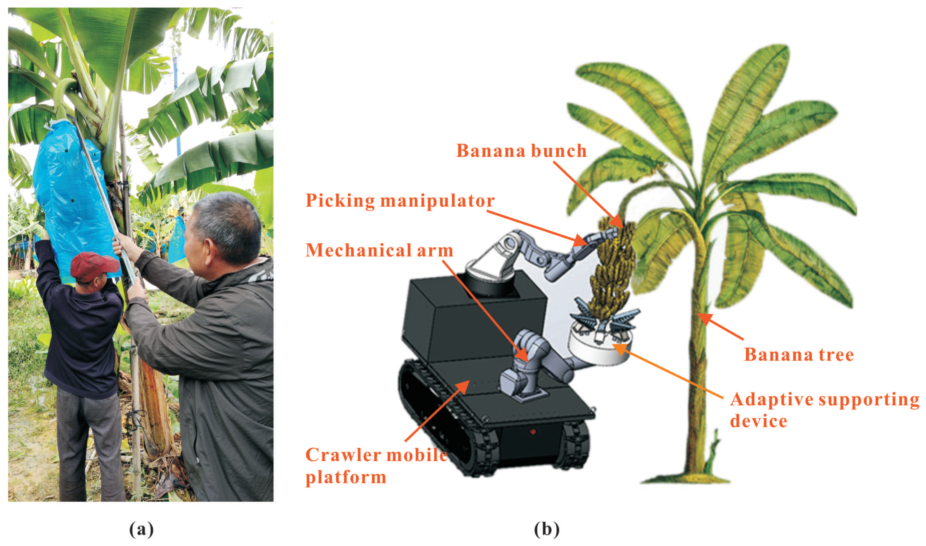
Banana harvest is still in the manual stage. Usually, two or three people are required to harvest one banana bunch. One person is responsible for lifting the banana bunch and transporting it, while another person cuts the banana stalk, as shown in Figure 1a. The manual harvest of bananas requires huge manpower and has high labor intensity [3]. With the intensification of the aging population and the shortage of labor, it is urgent to develop machines to complete the banana harvesting work instead of manual labor [4].
Researchers from all over the world have carried out many studies on the robotic harvesting of various fruits and vegetables [5,6], for example the tomato picking robot [7], strawberry picking robot [8,9], watermelon harvesting robot [10], and the lettuce harvesting robot [11]. Compared with picking machines, these picking robots are more automated and intelligent. They have already achieved the basic function of harvesting the target, liberating people from heavy labor. However, the existing robots usually use a single picking manipulator to directly grab the fruits.
Unlike the above-mentioned fruits and vegetables, a banana bunch is bulky, whose weight can even exceed 40 kg. Due to the heave weight, it is difficult to grip the banana bunch by the existing fruit or vegetable picking robots [12,13]. The Western Australia Department of Agriculture designed a banana picker based on an excavator [14], but the machine was too bulky for banana plantations. The banana picking machine designed by Tang [2] can better complete the mechanized banana picking work, but it still uses one single manipulator for harvesting. It requires a large amount of power and bears a large load, which may cause the machine to overturn. Duan et al. [15,16] studied a semi-automatic banana picking and harvesting machine. They designed a banana supporting device composed of rigid plates, springs, and sensors to support the banana stalk. This device cooperates with the clamping and cutting device to complete the banana harvest, which reduces the load of the manipulator to a certain extent and reduces the possibility of the machine overturning. However, the rigid supporting structure will cause greater damage to bananas and seriously affects the quality of bananas. It does not take into account the characteristic of banana bunches, including the shape, size, and the difference between banana hands. These will affect the quality of the support.
To solve the above problems, this paper proposes a flexible supporting device to cooperate with the banana picking manipulator. The cooperation between the picking manipulator and supporting device is shown in Figure 1b. The process of banana harvest is as follows. First, the manipulator locates and grips the top position of the banana stalk [17,18,19]. Then, the flexible supporting device moves to the bottom of the banana bunch and supports the banana bunch. Finally, the picking manipulator simply cuts and holds the banana stalk. To make the flexible supporting device more adaptive, the Fin-Ray finger [20,21] was adopted in our design. As a typical compliant mechanisms [22,23], the Fin-Ray finger is widely used in the field of fruit picking due to its good flexibility and adaptability.
2. Principle and Structure of the Supporting Device
2.1. Parameters of the Banana Bunch
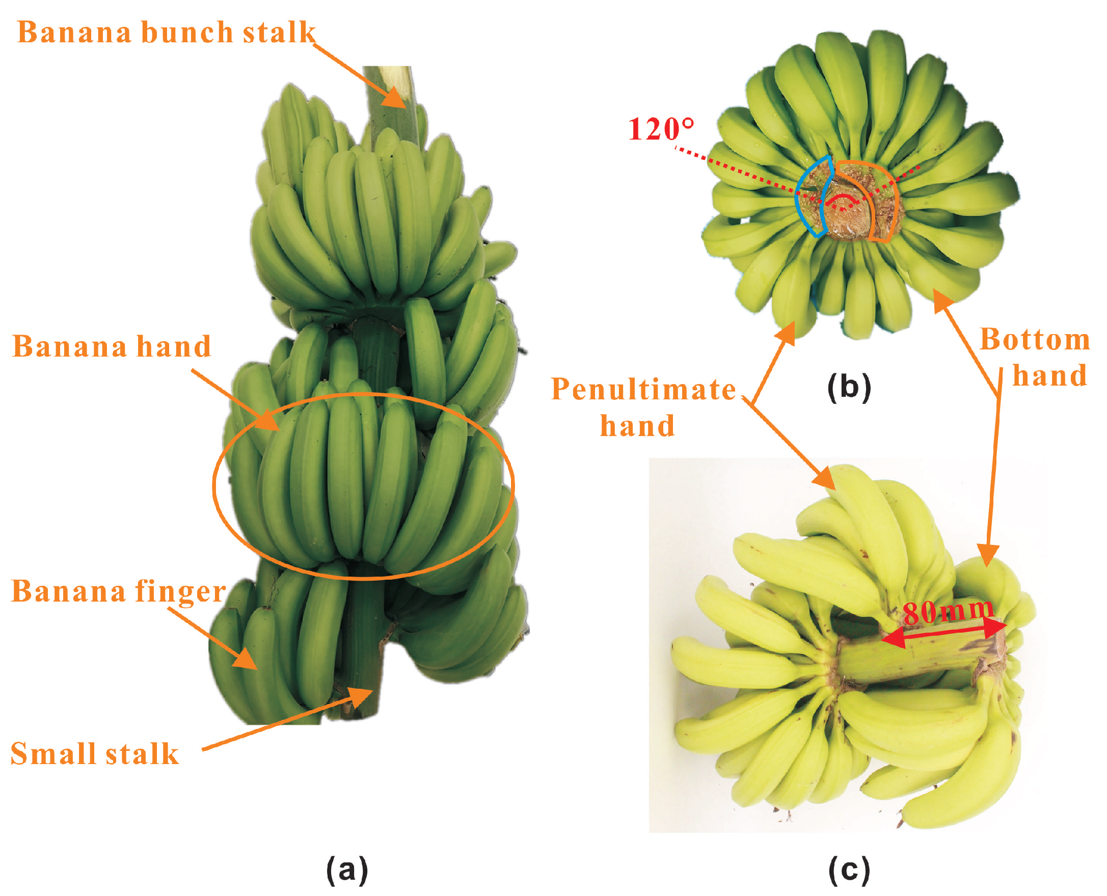
The flexible supporting device designed in this paper works on the whole banana bunch during harvest, as shown in Figure 2a. Therefore, the parameters of the banana bunch were studied [24,25]. Banana bunches have the following characteristics. First, there are many kinds of bananas, including powder bananas, ivory bananas, longya bananas, etc. Their individual differences are obvious, with different dimensions, and the weight of the banana bunch is heavy. Second, the banana hands grow asymmetrically around the banana stalk. There are certain height differences and angle differences between neighboring banana hands. The penultimate hand is often higher than the bottom hand, as shown in Figure 2b,c. Third, the banana finger is very easily damaged [26]. We measured the various parameters of the whole banana bunch, and the main parameters of the banana bunch are shown in Table 1.
2.2. Structural Design of the Supporting Device
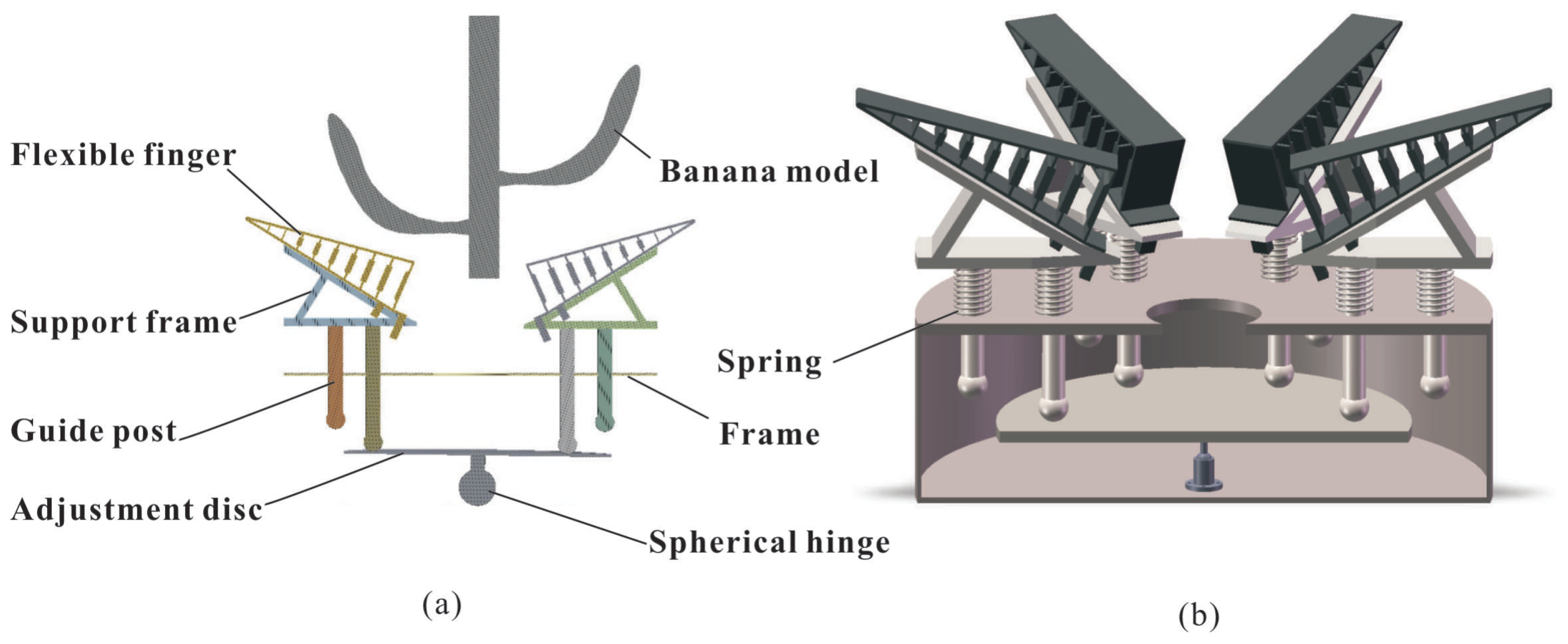
According to the above characteristics of the banana bunch, an adaptive supporting device was designed. The device mainly included two parts: the flexible contact part and the height difference self-adjusting part. Figure 3a is a schematic of the device, and Figure 3b is a cross-sectional view of the whole device. The flexible contact part mainly plays the role of supporting and wrapping the bottom of the banana bunch and solves the problem of damage during the banana supporting process. The height difference self-adjusting part adjusts the position of the flexible contact part, so that the entire supporting device has a better supporting and wrapping effect. According to the fact that the banana bunch bottom is near-spherical and the diameter is between 300 mm and 450 mm, we designed the entire supporting device with a diameter of 500 mm.
2.2.1. Design of the Flexible Contact Part
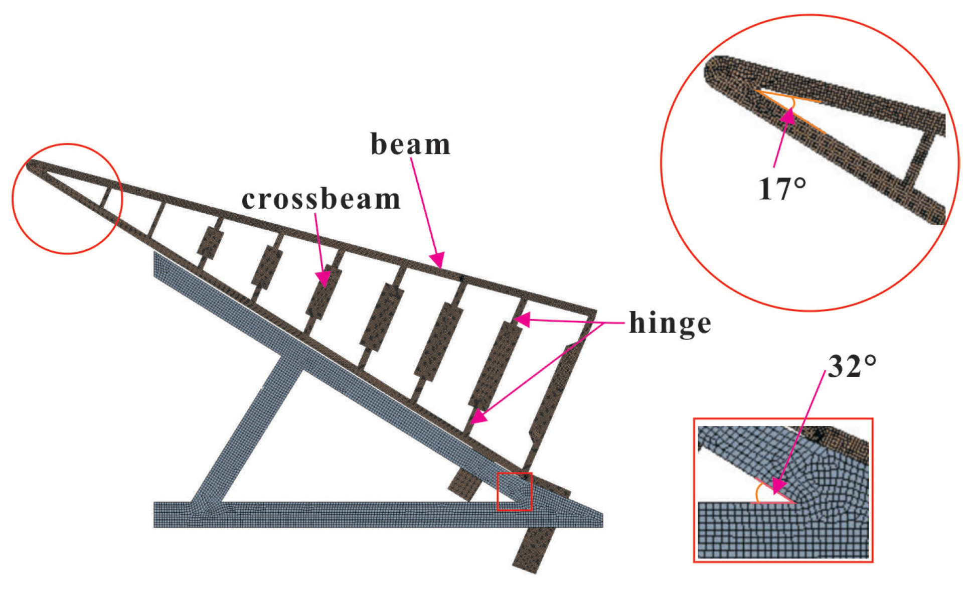
Due to the large weight characteristic of banana bunches, it is better to increase the contact area between the banana bunch and supporting device, which will consequently reduce the contact stress on the banana fingers. For this reason, the flexible contact part, i.e., the core component of the supporting device, was designed by using several flexible fingers and rigid triangular supporting frames. These flexible fingers were based on the Fin-Ray effect [27], which has been widely used in fruit picking robots due to its good shape and size adaptability [12,28]. As one kind of compliant mechanism, the Fin-Ray finger is shown in Figure 4. It was formed from two flexible beams and multiple crossbeams. For the flexible contact part in this paper, six Fin-Ray effect fingers of the same geometry were used and distributed symmetrically around the banana bunch stalk. As a result, the flexible contact part can achieve flexible wrapping and support when contacting the bottom of the banana bunch. Thanks to the Fin-Ray effect, it can perfectly fit the banana surface and has good adaptability for different shapes and sizes of bananas.
By considering the dimension of the banana hand at the end of the banana bunch (150 mm–200 mm), the total length of the flexible finger was set to 250 mm. In order to make the fingers have good flexibility, multiple flexible crossbeams of unequal width were designed inside the fingers. The angle between the upper and lower beams was designed to be , as shown in Figure 4.
The flexible contact part not only plays the role of supporting the bananas, but also realizes the lateral wrapping of the banana bunch, so that the banana does not turn over. Thus, we used the rigid supporting frame with an included angle of to fix the flexible fingers. The advantage of this design is that the lower part of the flexible fingers will be the first to contact the bottom of the banana bunch. This will drive the tip of the flexible fingers to deform towards the center of the banana bunch during the downward movement of the banana bunch, i.e., realize the function of laterally wrapping the banana bunch.
2.2.2. Design of the Height Difference Self-Adjusting Part
As shown in Figure 2b,c, the minimum height difference between the last two hands of the banana bunch is 40 mm, while the maximum distance is 80 mm. The included angle between the two hands is about . To some extent, the flexible fingers can be adapted to the height difference, but 80 mm will be too large for the fingers. As a result, the flexible fingers under the penultimate hand cannot contact the target. The device cannot accurately and properly wrap the banana bunch. To this end, we tactfully used the biological characteristics of the banana hands themselves, which is the height difference. Then, we adopted the principle of the lever to design a height difference self-adjusting structure for the flexible supporting device. The height difference self-adjusting part mainly included the spherical hinge, adjusting disc, springs, and guided pillars.
The working process of the height difference self-adjusting mechanism is as follows. First, the banana bunch with the height difference begins to fall, as shown in Figure 15b,e. The bottom banana hand is the first to contact the flexible fingers, while further pressing the rigid supporting structures and guided pillars. Then, the spherical hinge rotates under the force, and the other end of the adjusting disc is tilted up due to the principle of the lever. Then, the flexible contact structures on the opposite side move upward and contact the penultimate hand, as shown in Figures 9c and 15c,f. At this time, all parts of the supporting device reach a mechanical equilibrium state. We can see from Figure 15d that all the flexible contact parts are in the proper positions. Finally, when the banana bunch continues to press on the device, all the flexible fingers will deform and wrap the bananas.
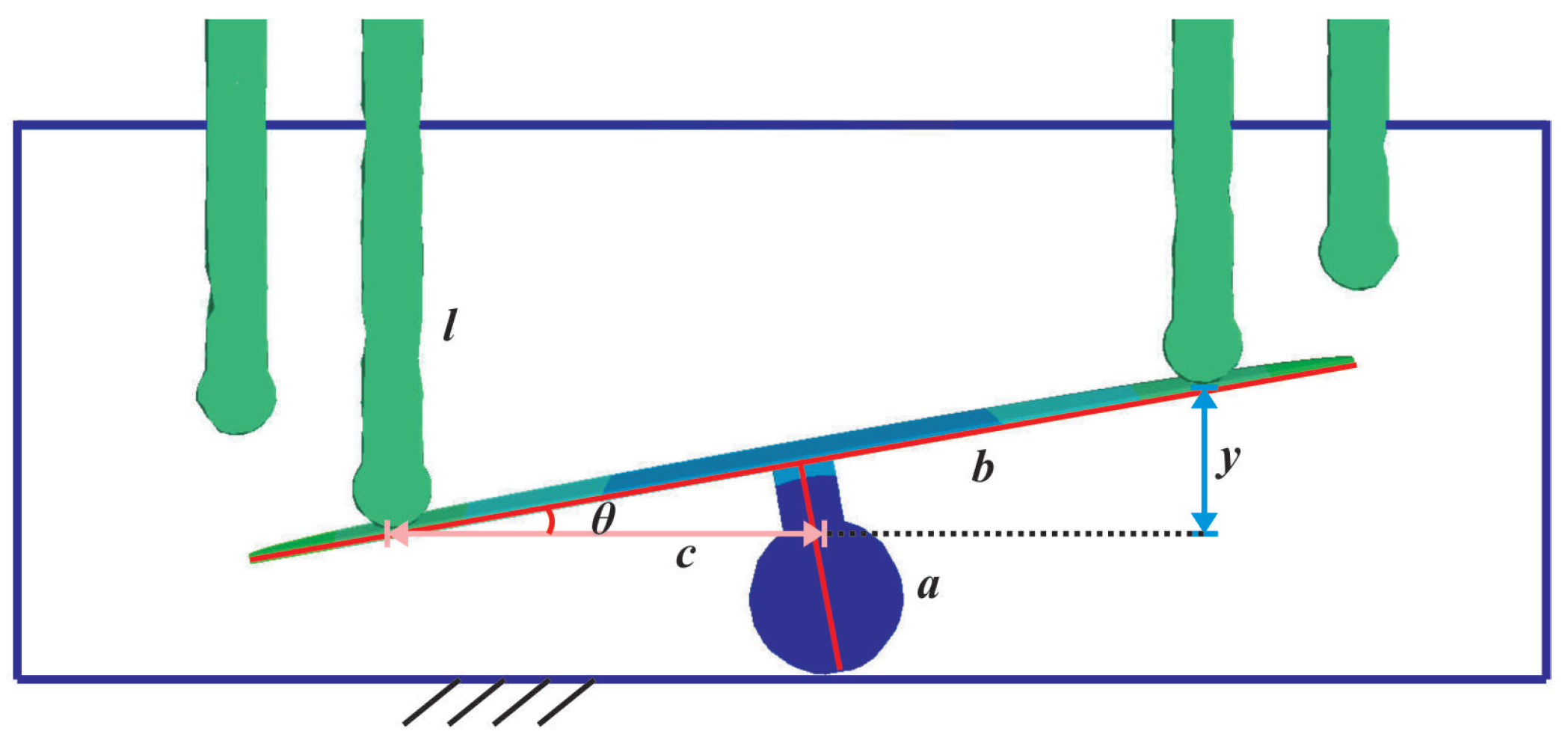
To make the upper limit of the height compensation reach 80 mm, according to the symmetry principle, the long guided pillar’s maximum downward moving distance should be 40 mm, as show in Figure 5. Therefore, it was calculated that the maximum rotation angle of the spherical hinge was , .
If the flexible contact part moves down too fast, it may be in a poor posture and cause unnecessary damage to the bananas. Compression springs, whose stiffness coefficients were 80 N/m, were set under all the guided pillars to support the weight of the flexible contact parts and the banana bunch. They will slow down the downward speed of the flexible contact part, which plays the role of damping and cushioning.
3. The Simulation Analysis
In this section, a series of finite-element simulations were conducted on Ansys Workbench to analyze the adaptability and practicability of the device.
3.1. Parameter Fitting of the Flexible Material
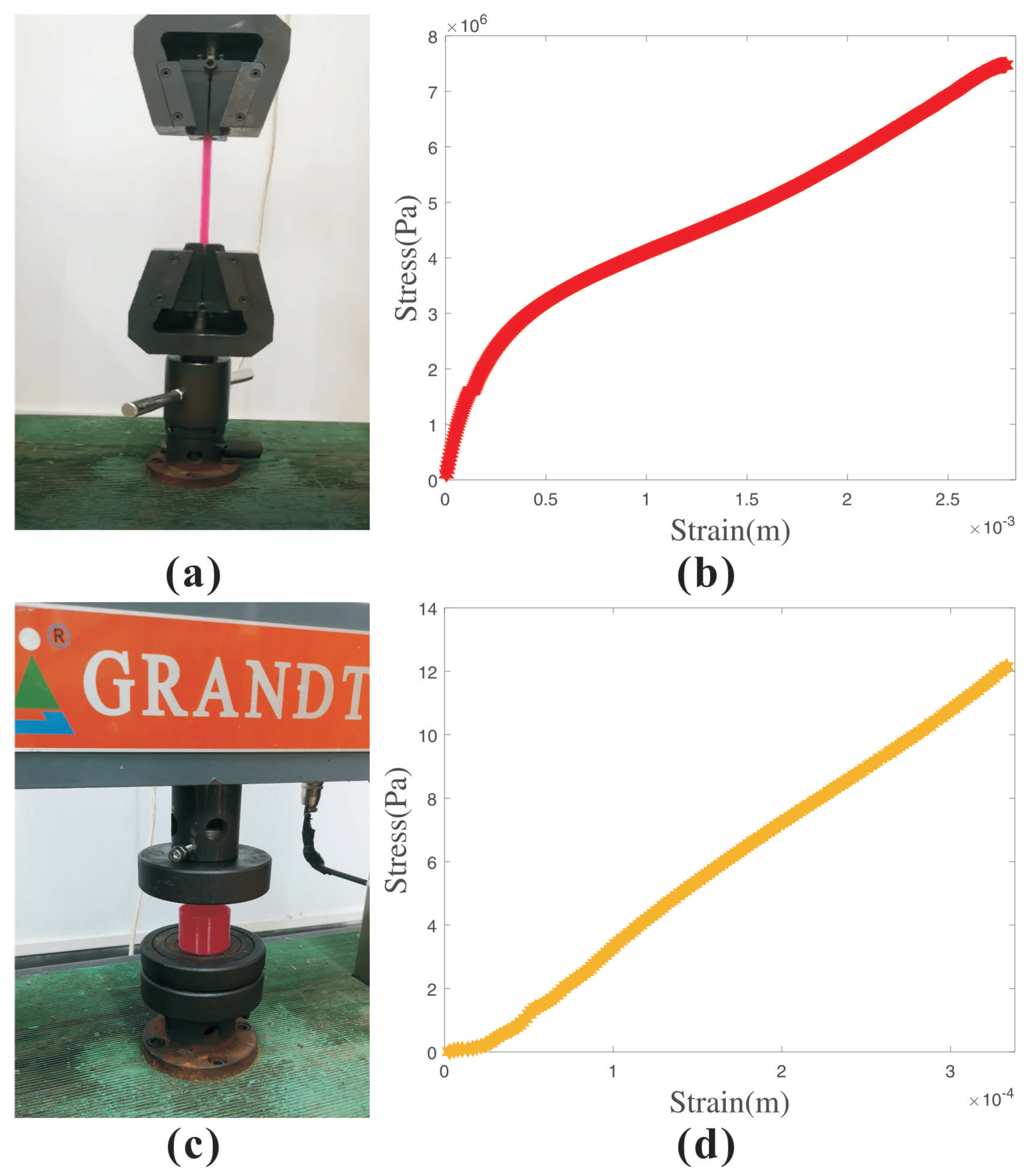
The adaptive flexible contact part requires sufficient flexibility [29,30]. For this reason, we used Thermoplastic Polyurethane (TPU) and 3D printing to make the flexible fingers [31]. However, the existing simulation material library does not have the relevant parameters of TPU materials. To obtain the material parameters, a series of experimental analyses were carried out in this section. We used the universal tester to test the material properties of the TPU. The tensile test and compression test are shown in Figure 6a,c. Figure 6b,d shows the stress–strain curves obtained by the tensile and compression tests, respectively. According to the analysis of the test results, the ultimate stress of the TPU material was MPa.
As one kind of rubber-like non-compressible nonlinear materials, the TPU material’s mechanical properties can be described by the Mooney–Rivlin strain energy function, which is a polynomial strain energy function and is extensively used in finite-element analysis. Its constitutive model can better describe the hyperelastic properties of rubber-like materials at small and medium strains [32,33], and its constitutive relationship is as follows:
where is the strain energy density, is the order of the function, is the material constant, and and are the first- and second-order strain invariants, respectively. is the material constant, which is related to the compressibility of the material. is the volume ratio. , , and are the main elongations. Its strain energy density function expression is as follows:
According to the non-compressibility of rubber materials and the relationship between the Kirchhoff stress tensor and Green strain tensor [32,33], we can obtain the relationship between the principal stress and the principal elongation ratio of the TPU material under the uniaxial tensile test conditions as follows:
where is the strain in the tensile direction. Substituting Equation (4) into Equation (5), we can obtain:
Finally, after sorting the experimental data and performing regression analysis, we obtained the Mooney–Rivlin correlation constants, i.e., and , which establish the material foundation for the subsequent mechanical simulations of the flexible fingers.
3.2. Analysis of the Device Adaptability
In this section, the shape adaptability, size adaptability, and height difference adaptability of the device were studied. Without losing generality, we took out a pair of flexible fingers as a simplified model for a better view of the result and more efficient computation, because the flexible fingers were distributed symmetrically. The material of the triangular supporting frame was set to structural steel. Using the above fitting material parameters, the flexible fingers were set to the TPU material. The mesh of the generated flexible contact part model is shown in Figure 4.
3.2.1. Shape Adaptability
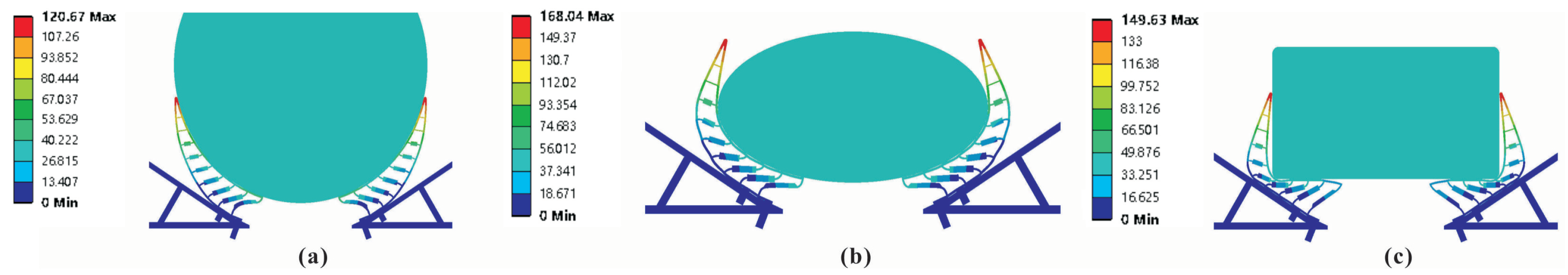
First of all, we used different modes, such as circular, elliptical, and rectangular cross-sections, to verify the shape adaptability of the flexible contact part. Its deformation diagram is shown in Figure 7. In Figure 7a, the flexible fingers had a good self-adaptive performance to the circular cross-section. In addition, there was a relatively perfect fit and wrapping effect between the upper beams of the fingers and the circular model. The deformation diagram of the elliptical model in Figure 7b clearly shows that the supporting effect of flexible fingers on the bottom of the object and the side-wrapping effect were also significant. Although there was a certain gap between the rectangular object and the flexible fingers in Figure 7c, the flexible fingers had a good adaptive effect on the rectangular cross-section and could effectively support and wrap the object. According to the total deformation diagram of flexible contact structures, the maximum deformation occurred at the position where the flexible finger first touched the grasping object. We used this position as the base point. As it approached the two ends of finger, the deformation of the flexible finger gradually decreased.
From the above results, the flexible contact part had great shape adaptability for grasping objects with a larger curvature and good shape adaptability for small curvatures or sharp corners. It also proved that the angle setting of the flexible finger and the supporting frame was appropriate.
3.2.2. Size Adaptability
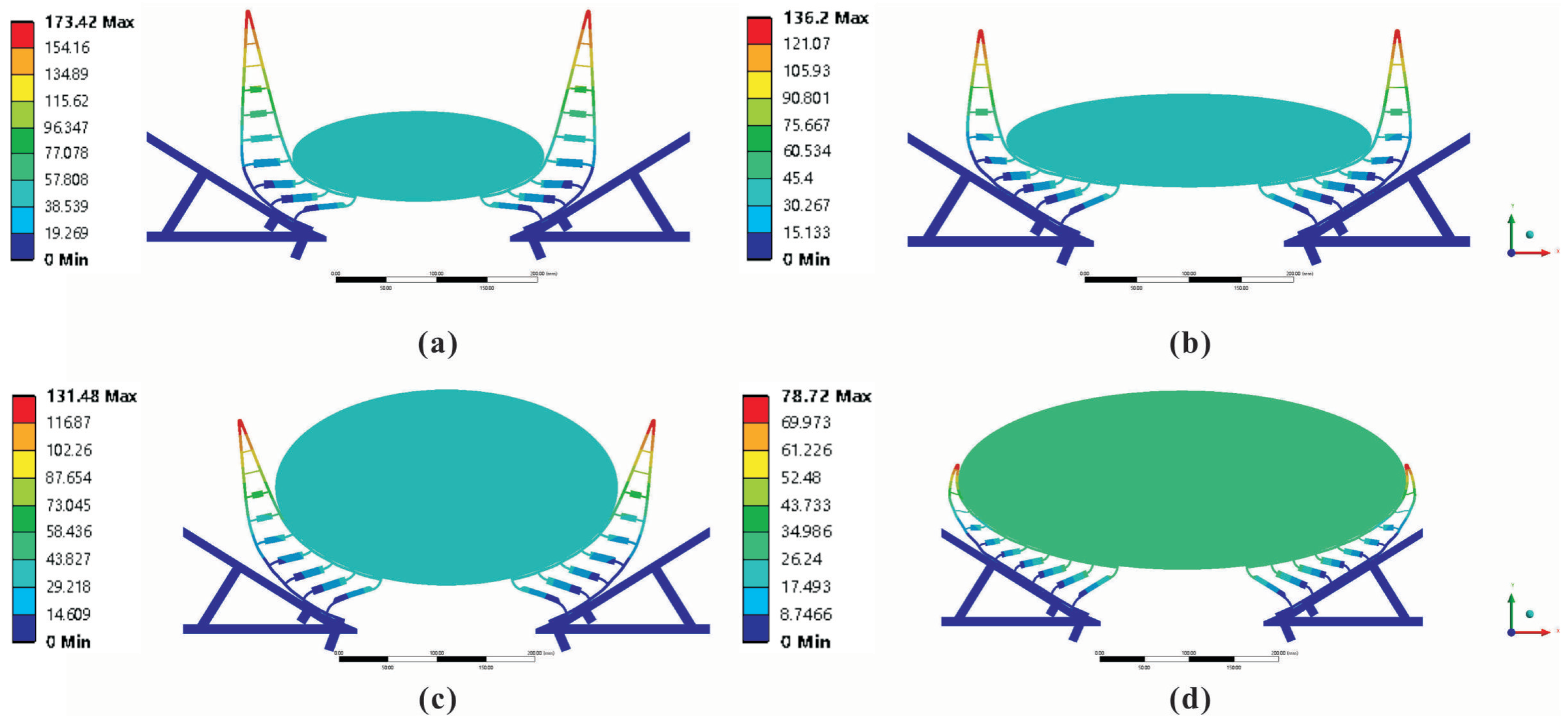
Then, taking the elliptical cross-section model as an example, we built models of different sizes, as shown in Figure 8. The major axes of these elliptical models were 250 mm, 350 mm, and 500 mm, while the minor axes had two groups of 90 mm and 200 mm. These models were used to analyze and study the size adaptive capability of the contact part.
From the overall deformation diagrams in Figure 8, it can be seen that the contact parts had good wrapping capacity and adaptability for models of different sizes. There were three crossbeams deformed in Figure 8a. When the major axis increased to 350 mm, there were five main deformed flexible crossbeams, as shown in Figure 8b. While the deformation at the end of the flexible finger increased, the supporting capacity at the bottom of the model also increased. Comparing Figure 8b with Figure 8c, the flexible fingers had good a fit for the model with a smaller curvature. In the case of the same moving distance of the model, the larger the minor axis, the better the wrapping effect was. Regarding Figure 8d, when the minor axis of the ellipse was 200 mm and the major axis was 500 mm, the adaptability of the flexible contact parts was still good, and the lateral wrapping effect was also significant.
To sum up, the flexible finger had good size adaptability. According to the current angular position and finger size, it could be well adapted to objects with a span of 250 mm to 500 mm in length. It also had an apparent adaptive wrapping effect for objects with a smaller curvature.
3.2.3. Height Difference Adaptability
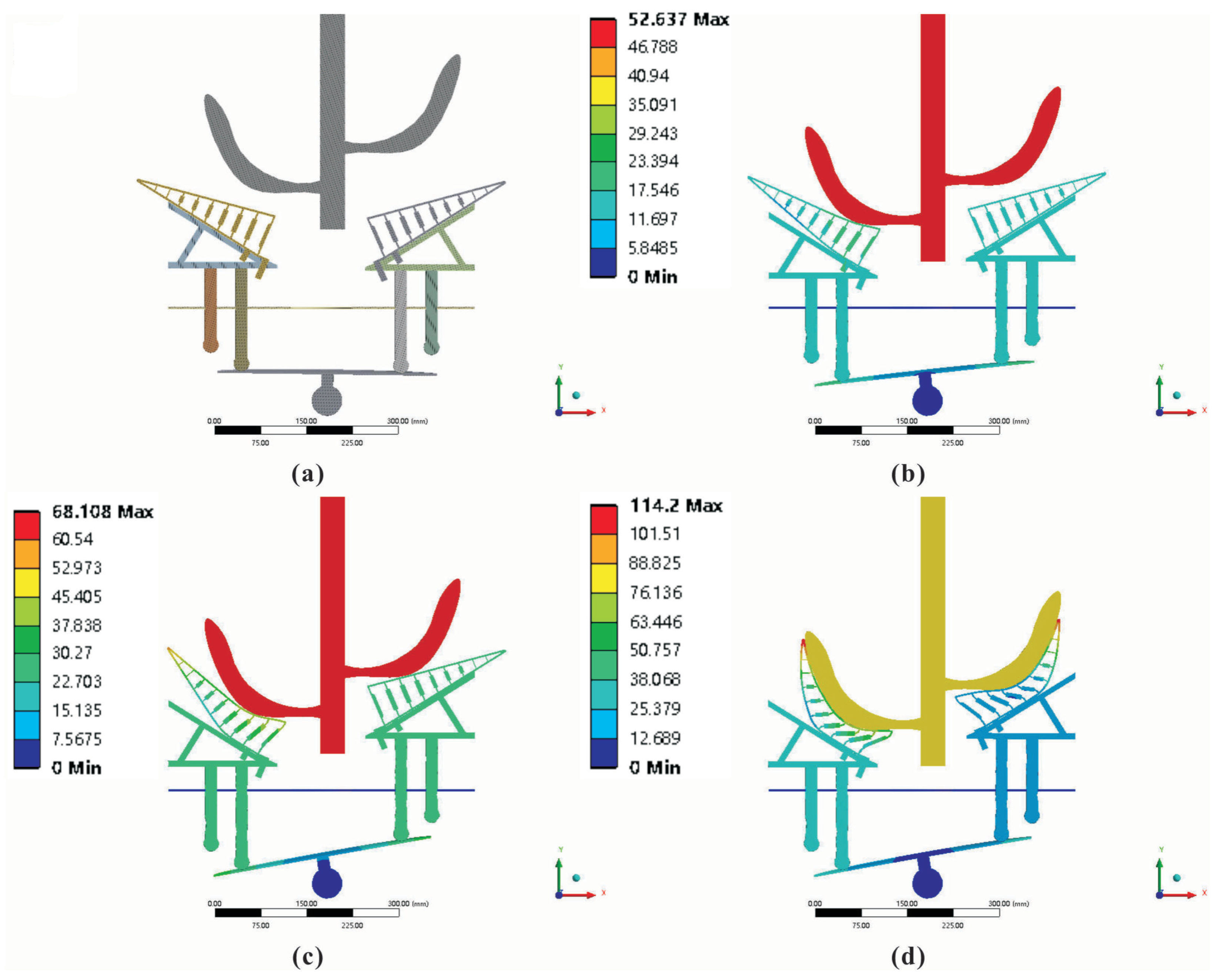
To verify the adaptability of the flexible finger in the process of height adjustment, we established a banana model with a 60 mm height difference between the last two hands, as shown in Figure 9a. After adding the spring action, the simulation of the height difference adaptability in the supporting process was carried out.
As shown in Figure 9b, when the bottom hand of the banana model first touched the flexible finger, the flexible finger underwent a small deformation at the tangent position that contacted the banana. When the banana model was pressed down further, the flexible fingers driven by the bottom hand started to move down slowly due to the effect of the compression springs. The banana stayed in contact with the flexible finger, but the deformation speed of the flexible finger began to slow down. When the device reached the state shown in Figure 9c, the opposing flexible fingers moved upward, under the action of the principle of leverage. The flexible fingers under the bottom hand were partially deformed and basically achieved a good supporting effect for the bottom of the banana. The penultimate hand also contacted the flexible fingers at the tangent position. When the banana model continued to be pressed down, it entered the state shown in Figure 9d. The flexible fingers under the bottom hand were deformed greatly and had good effect of fitting and wrapping of the bananas. In this state, the flexible fingers under the penultimate hand basically realized the overall wrapping and supporting of the bananas, but its deformation was smaller than that of the bottom hand.
In conclusion, the simulation analysis showed that the flexible contact parts had good adaptivity even when the banana hands had a height difference. It also could achieve a good supporting and wrapping effect.
3.3. Analysis of the Mechanical Properties
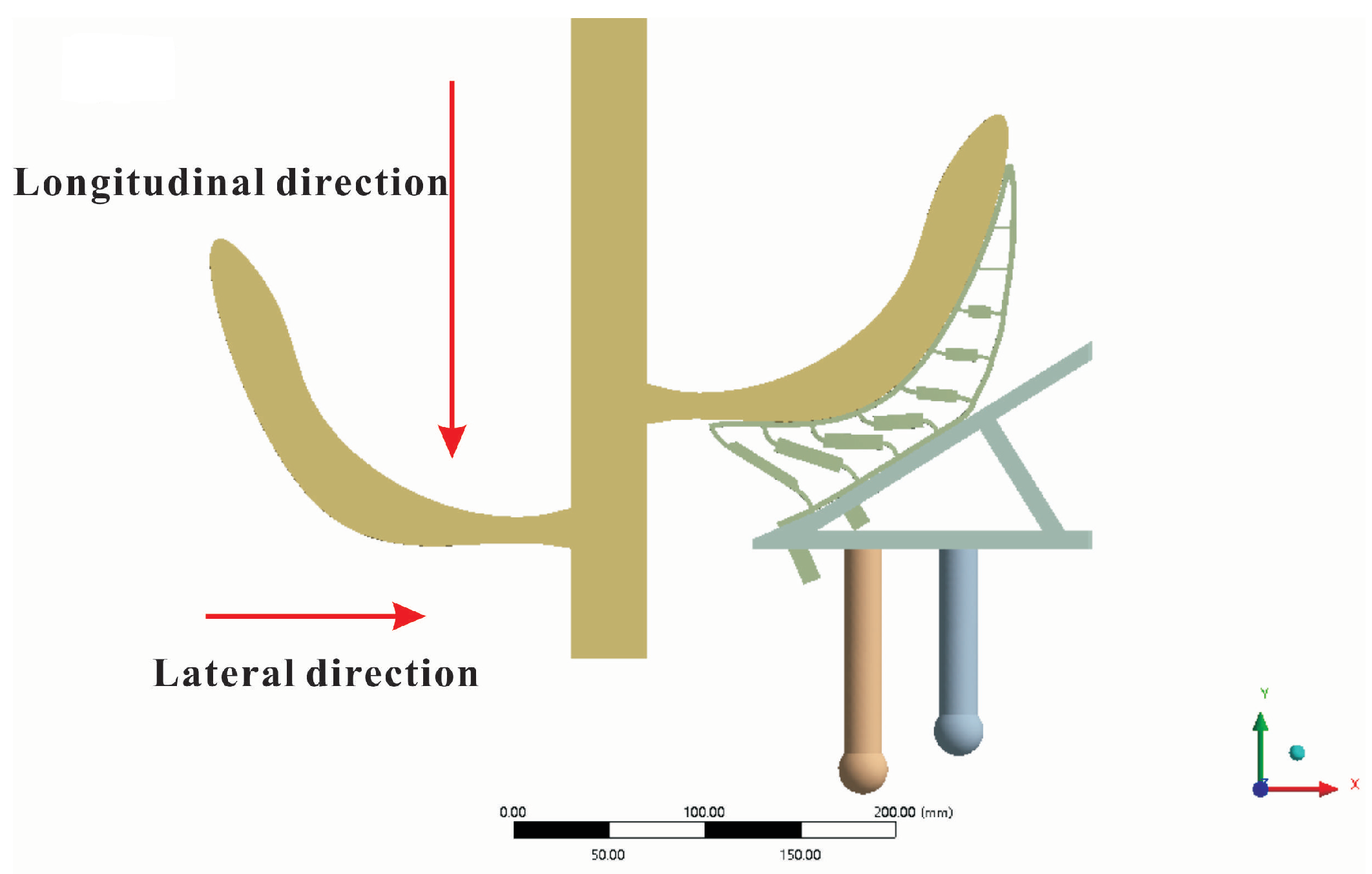
In order to analyze the functionality of the device, the mechanical properties of the supporting device were studied in this section. Those included longitudinal stiffness analysis, lateral stiffness analysis, banana stress analysis, and structure stress analysis. The loading direction is shown in Figure 10.
3.3.1. Longitudinal Stiffness Analysis
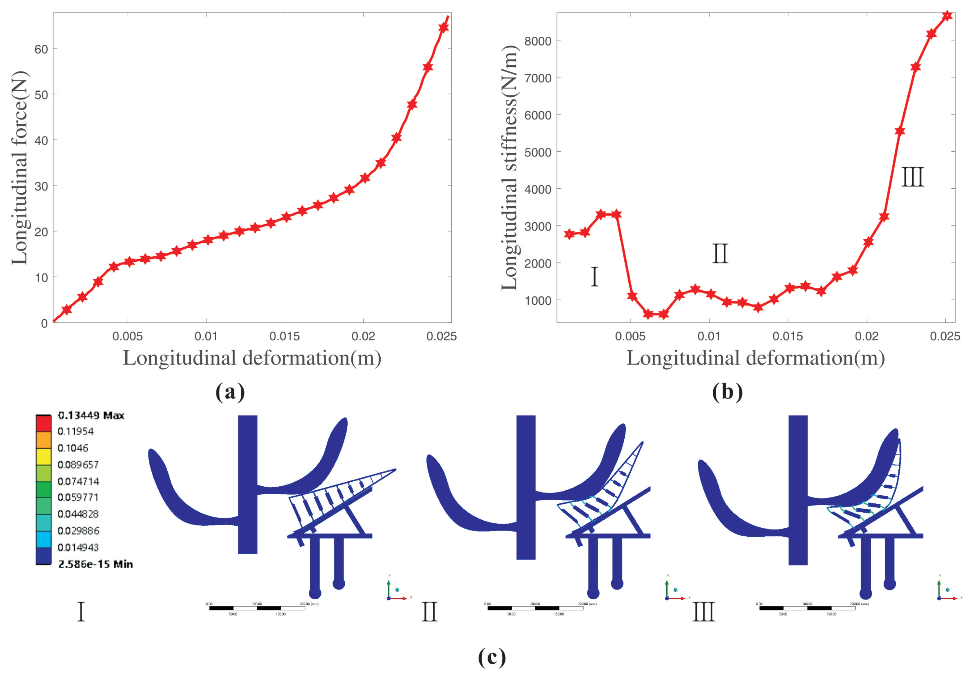
To verify the supporting effect of the flexible supporting device, we analyzed the longitudinal support strength of the device. There was a set of simulation analyses that included longitudinal force–deformation and longitudinal stiffness in this section [34,35]. The force—deformation curve of the longitudinal force loading is shown in Figure 11a,b along with the longitudinal stiffness curve.
As shown in Figure 11, the force rose with the increase of displacement during the whole longitudinal loading process. The stiffness variation corresponded to the force variation and could be roughly divided into three stages.
First, when the bottom hand of the bananas started to contact the flexible fingers, the longitudinal deformation of the device was mainly concentrated at the position where the banana contacted the flexible fingers. Please refer to Figure 15b,e and Figure 9b for the movement process. In this state, the crossbeams in the flexible finger were almost consistent with the normal of the banana skin. Therefore, the stiffness was relatively large. When it was initially compressed, the hinges at both ends of the crossbeams first deformed, and the longitudinal stiffness increased, as shown by I in Figure 11b,c. Then, as the longitudinal loading force was further increased, the crossbeams in the middle of the fingers began to deform toward the center of the frame. This made the crossbeam and the longitudinal loading direction increase in angle, and the overall longitudinal stiffness decreased rapidly, as shown in II in Figure 11c. After that, the crossbeams continued to deform, and their angular position also changed. Because multiple crossbeams were set in the flexible finger and the crossbeams influenced each other, the longitudinal stiffness of the device had a certain extent of fluctuation in phase II. Finally, the flexible finger completely wrapped the banana in the model. There were some length limitations of the crossbeams and the flexible hinges. The deformation of the beam on the upper end of the finger was also close to the limit. Thus, the overall longitudinal stiffness rose quickly, as shown in Figure 11b,c (III).
3.3.2. Lateral Stiffness Analysis
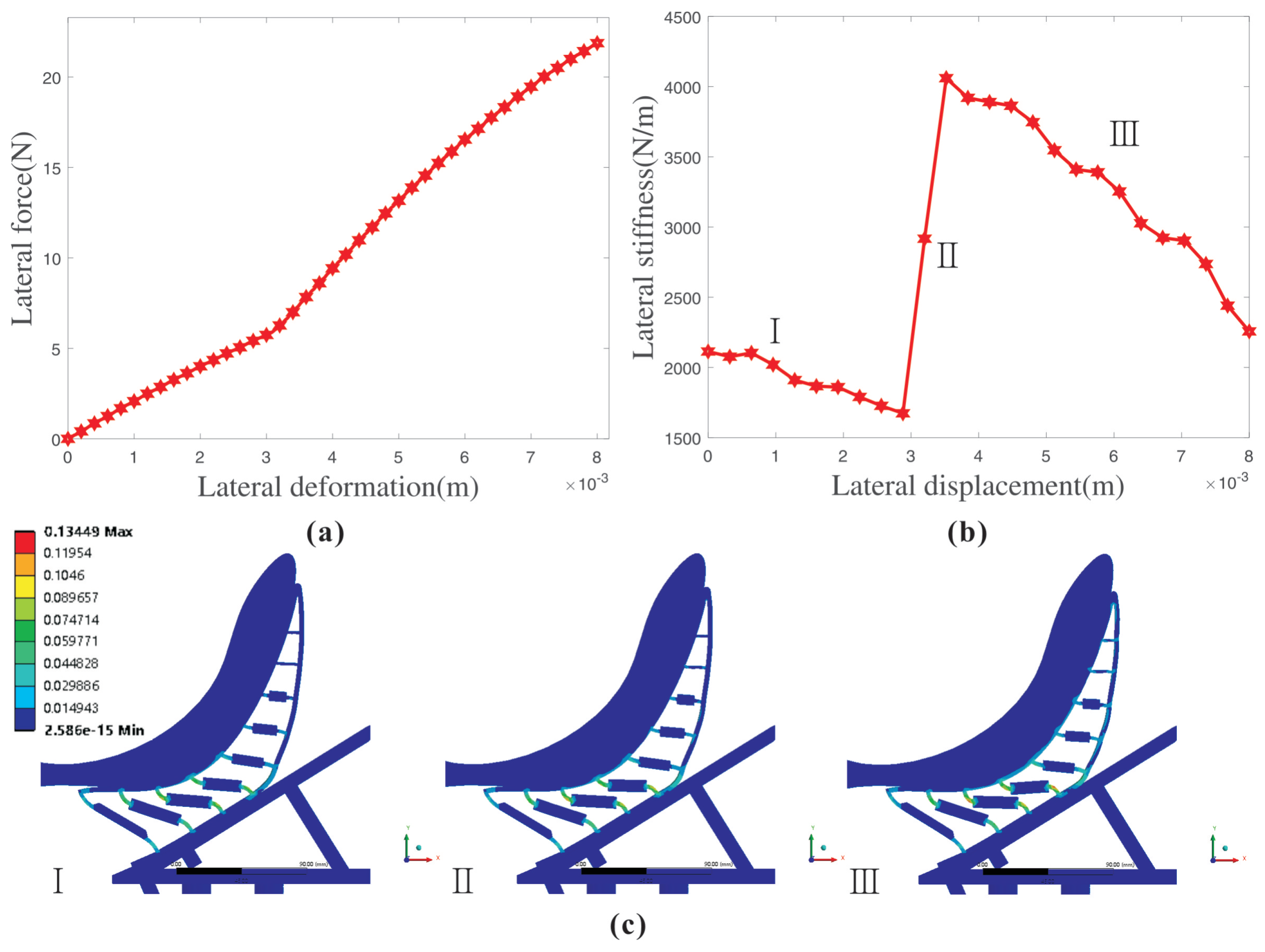
Considering that the banana bunch may tilt during the harvesting process, the lateral support strength of the supporting device to the banana was analyzed in this section. On the basis of applied longitudinal loading force of N, we additionally applied a horizontal force to the banana model. The loading direction is shown in Figure 10. The lateral stiffness of the device was analyzed in detail. The force–deformation curve during the lateral force loading process is shown in Figure 12a, and the lateral stiffness variation curve is shown in Figure 12b. From the figures, as the lateral displacement increased, the lateral force of the device tended to rise. In addition, its ascent speed changed with the lateral stiffness.
First of all, when the lateral load was not applied, the direction of the crossbeams in the flexible finger was parallel with the loading direction. Therefore, the lateral stiffness at this time was relatively large. When the applied lateral force was small, the flexible finger underwent a small lateral deformation. The crossbeams on the flexible fingers had certain position and angle variations along the direction away from the center of the frame. The directions of the crossbeams were no longer consistent with the loading direction at this moment, and a certain angle was formed between the two. That caused the lateral stiffness of the device to show a downward trend, as shown in I in Figure 12b,c. Then, with the further increase of the lateral loading force, the direction of the crossbeams near the tip of the finger tended to be horizontal. Meanwhile, the deformations of the beams on the upper and lower ends of the fingers reached the limit, limiting the lateral deformation of the fingers. Thus, the lateral stiffness increased rapidly. As shown in II in Figure 12b,c, the critical position was reached at this time, and the maximum lateral stiffness was 4060 N/m. Finally, when the lateral force loading continued to increase, the crossbeams near the tip of the finger deviated from the horizontal direction again. That created an angle with the loading direction. The crossbeams at the end of the finger tended to deviate from the loading direction, and the hinges at both ends of the crossbeam deformed greatly. The above caused the lateral stiffness of the device to generally begin to show a downward trend, as shown in Figure 12b,c (III).
Both the longitudinal stiffness and the lateral stiffness were mainly affected by the crossbeams in the flexible fingers, including variations in the relative position and angle of the crossbeams. When the crossbeams were parallel with the loading direction, the stiffness increased. When the crossbeams deviated from the loading direction, the stiffness decreased, and the greater the deviation, the smaller the stiffness was. The length of the beams and the length of the hinges would also have a certain effect on the stiffness of the device, which is mainly reflected by the fact that when the deformation reaches the limit, they would limit the deformation and make the stiffness increase rapidly. The variation of longitudinal stiffness reflects the good supporting ability of the device. The greater the lateral stiffness in the supporting process, the better the lateral wrapping capability was.
3.3.3. Resulting Stress on the Banana
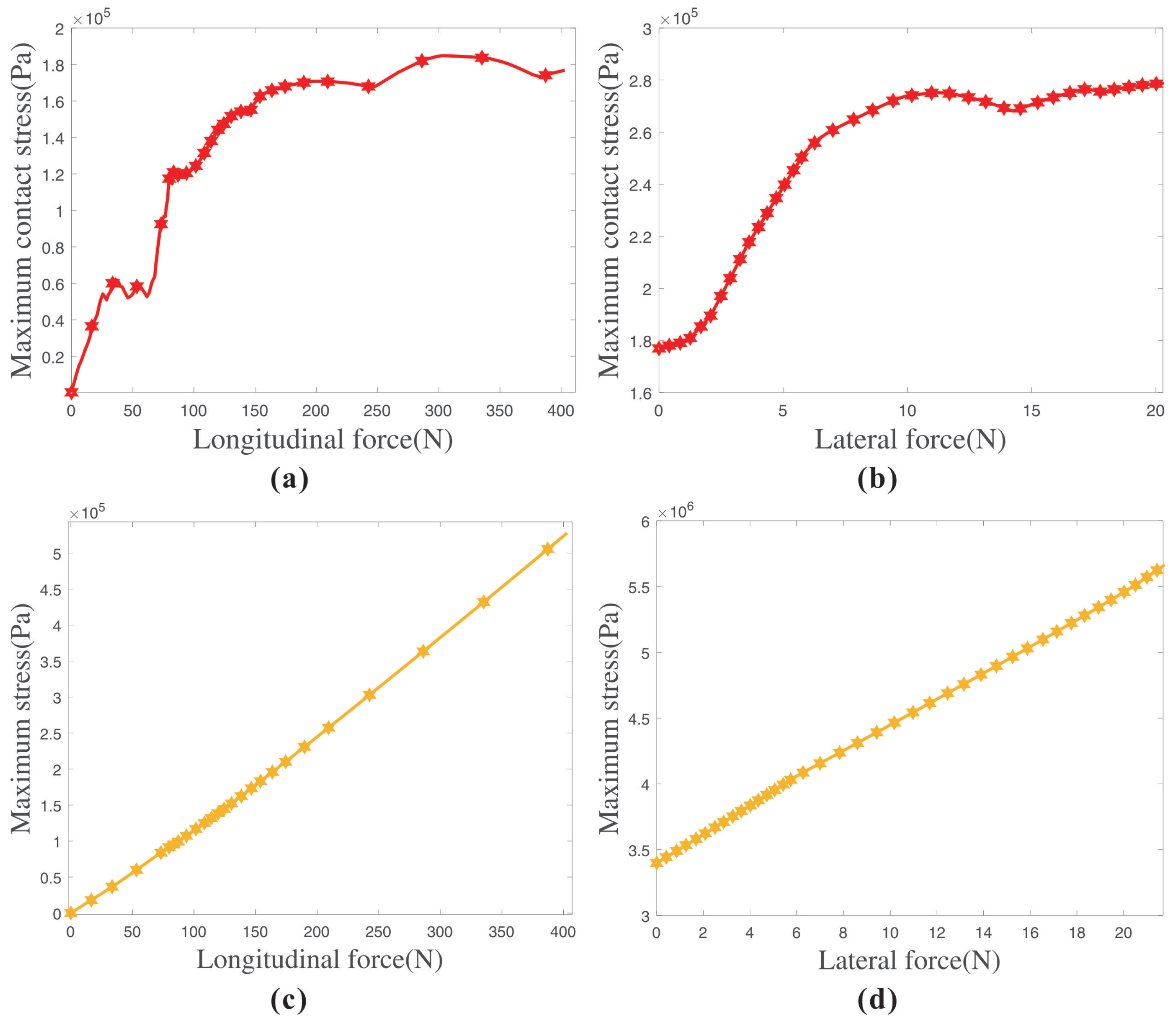
Bananas are very susceptible to collision damage, which will seriously affect the quality of the fruit. Small damage is an important evaluation index of flexible supporting devices. We counted the maximum contact stress on the banana skin, and its curve variation is shown in Figure 13a. The upper limit of longitudinal loading was N, which means that the weight of the supporting banana was within 40 kg. From the figure, we can ascertain that the maximum contact stress on the banana skin was about MPa, when the weight of the banana bunch was N. That is much smaller than the damage stress of the banana skin of MPa [36,37].
The longitudinal deformations under different conditions would also cause different results of the lateral wrapping of the flexible fingers. Therefore, based on the longitudinal analysis, we analyzed and studied the maximum contact stress experienced by the banana skin in the lateral direction. Under lateral loading, the stress curve is shown in Figure 13b. As the lateral loading force continued to increase, the maximum contact stress on the banana skin also increased. In our statistical data, when the lateral loading force reached N, the contact stress on the banana skin was about MPa, which is still smaller than its damage stress.
In addition to the contact stress, it is also necessary to consider whether the banana hands will fall off the bunch during the harvesting process. Therefore, we analyzed the stress on the whole banana bunch. The maximum stress for the whole banana bunch was concentrated at the position where the banana handle connects to the banana bunch stalk. Its maximum stress variation curve is shown in Figure 13c,d. Figure 13c shows that the stress on the banana handle increased with the longitudinal loading force. Its maximum stress was about MPa. After the lateral loading force, the maximum stress was MPa. It is obvious that the maximum stress in both cases was less than the damage stress of the handle of MPa [36,37]. From the stress of the banana skin, banana bunch, and handle, the adaptive supporting device had good flexibility, and the stress on the banana was much less than its damage stress. This fully explains that the device could provide better protection for bananas during the banana harvesting process and improve the fruit quality.
3.3.4. Structure Stress of the Device
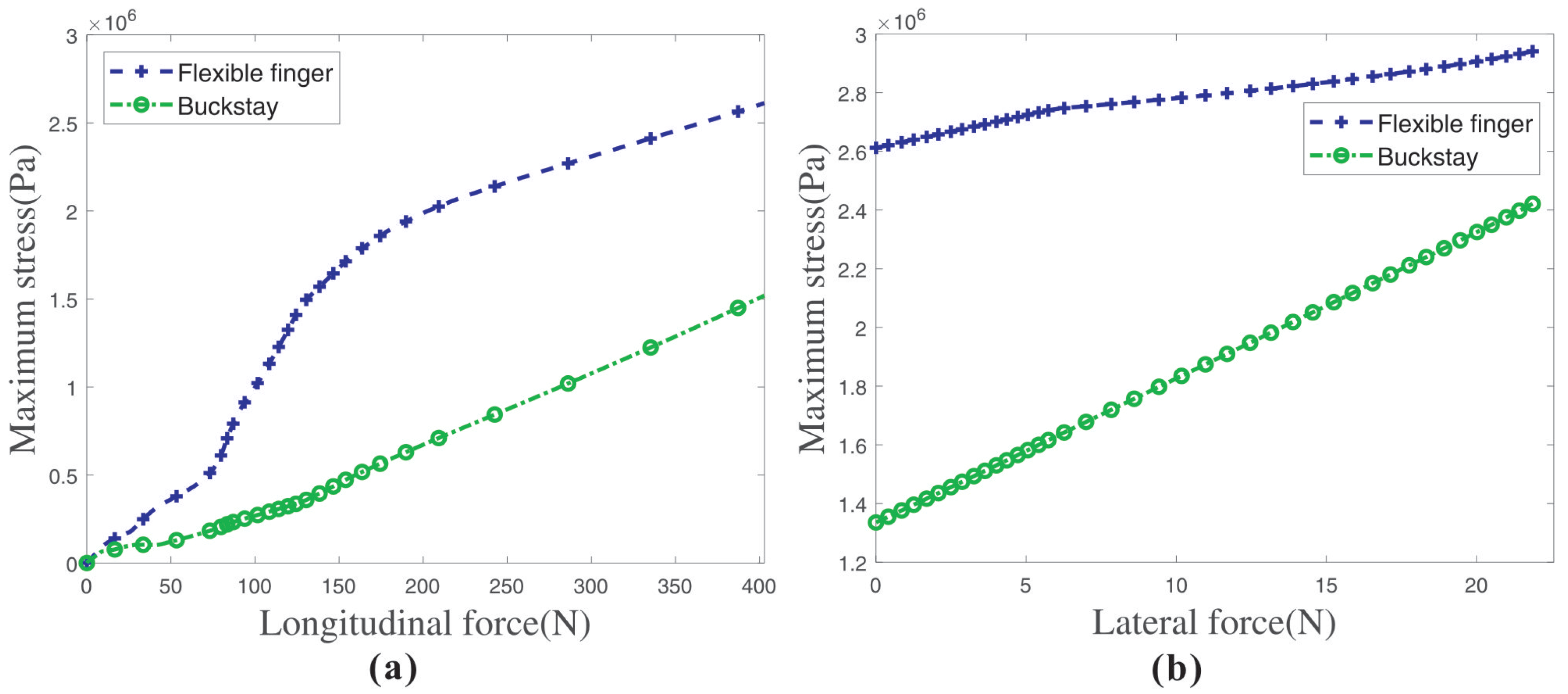
To test the working safety of the adaptive supporting device, we analyzed the stresses of the flexible fingers and rigid support structures. Their stress curves are shown in Figure 14. Only under the action of longitudinal force, the maximum stress of the flexible fingers was MPa. When the load force was lateral, the maximum stress was MPa. Both were much smaller than its ultimate stress of MPa. The maximum stress of the rigid support structure was MPa. Obviously, their maximum stress was much smaller than the ultimate stress. Therefore, the flexible fingers and the rigid supporting structures were not damaged during the entire operation.
4. Prototype Test and Analysis of the Whole Device
To evaluate the feasibility of the adaptive supporting device in banana harvest, we analyzed in detail the working process of the device in this section. Firstly, the entire adaptive supporting device was analyzed by finite-element simulation. The simulation analysis model is shown in Figure 15a.
The large span of the banana hands and the flexible fingers were distributed along the circumference. Thus, the bottom hand touched two sets of flexible fingers at least. Then, the parts moved downward with the guided pillars, and the speed gradually decreased due to the action of the compression spring. At the same time, this caused the rotation of the adjustable disc and the spherical hinge, that is the process from Figure 15b to Figure 15c. From Figure 15c,f, the flexible contact structures under the bottom hand arrived at the lowest position. Under the action of the adjusting disc, the flexible fingers in other positions moved upward. The positions of the flexible contact structures that were away from the bottom hand were slightly higher. Those under the penultimate hand were at the highest positions. When the penultimate hand touched the flexible fingers, the adjustment of the height difference was partially completed, as shown in Figure 15f. In this state, the bottom hand was basically wrapped by the finger, and the penultimate hand was about to enter the wrapped state. It is worth mentioning that the flexible fingers of the middle position rose to a certain height. They could limit the rotation of banana bunch. Finally, the banana continued to be pressed down. The device entered the equilibrium state shown in Figure 15d. The adjustment of the height difference and the entire supporting work were completed.
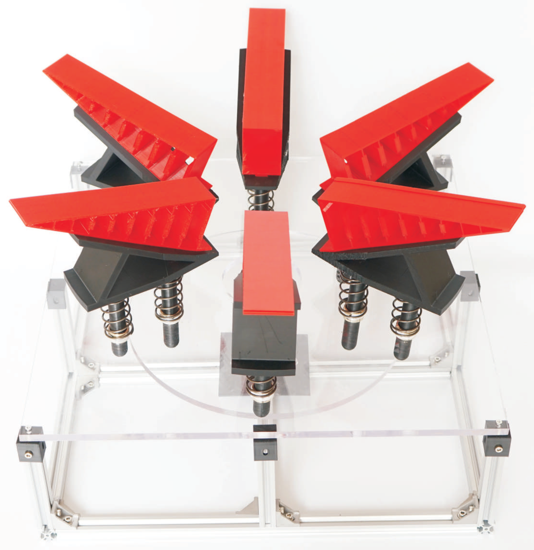
In order to reflect the supporting effect more truly, we used 3D-printing technology to make flexible fingers and build a prototype of the adaptive supporting device. The prototype is shown in Figure 16.
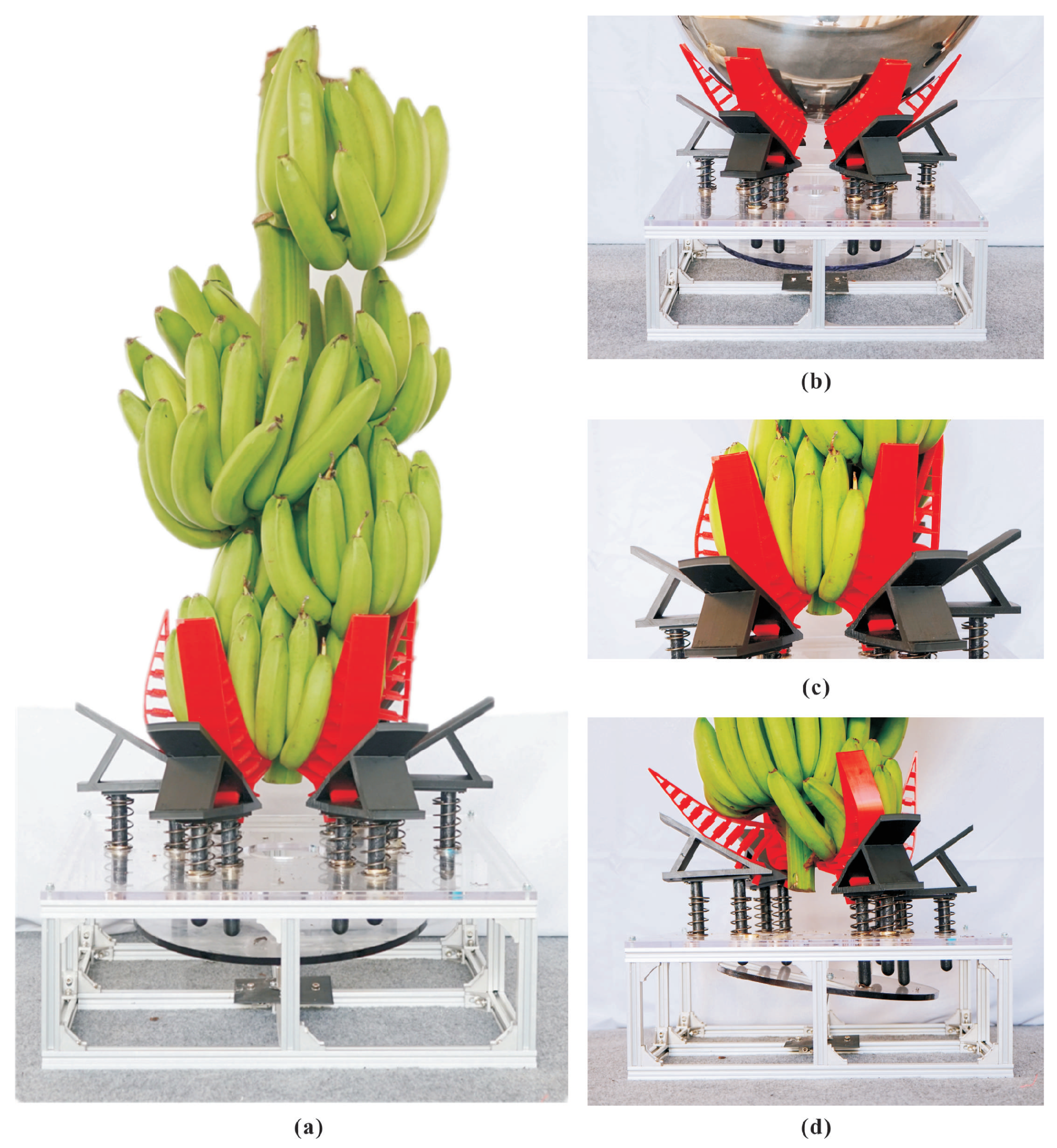
A supporting test was carried out on the banana bunch, and the test result is shown in Figure 17a. The picture proves that the device could complete the supporting work stably and basically realize the function of supporting and wrapping the banana bunch. Therefore, the design angle of the flexible finger and the rigid support was reasonable. The circularly distributed flexible contact parts could adapt to the shape and size of the banana, and the deformation wrapping effect is shown in Figure 17b,c. From Figure 17c, it can be found that the two flexible fingers close to the bottom hand bananas were tightly fit to the bananas, and the gap between the two was very small. The middle two flexible fingers were less deformed and had a larger gap from the bananas. This also corresponded to the previous simulation analysis results. Finally, we used a series of banana bunches with height differences to test the height difference self-adjusting effect of the device. The height difference of these bananas was between 40 mm and 80 mm. The test result of the height difference self-adjustment is shown in Figure 17d. From the picture, there was an angle between the adjusting disc and the horizontal direction. The flexible fingers under the penultimate hand were sent to a suitable height. The results showed that the height difference self-adjusting part could compensate for the existing height difference well and adjust the position of the flexible finger by itself, which promoted a better supporting and wrapping effect.
In summary, we tested the structure of the supporting device through simulation analysis of the working process and a prototype test. This proved the functionality and practicability of this adaptive supporting device and fully demonstrated the self-adaptive function and height difference self-adjustment function of the device, which could complete the banana supporting work stably and effectively.
5. Conclusions
This paper proposed and studied a flexible adaptive banana supporting device, whose structure was mainly composed of a flexible contact part and a height difference self-adjusting part. Through finite-element simulation, the shape adaptability, size adaptability, and height difference adaptability of the supporting device were studied. The results showed that the supporting device had a good self-adapting effect. Its stiffness and reliability were analyzed in this paper. The simulation results proved that the device was secure and stable during the supporting process. Through the stress analysis of the banana model, it was proven that the device did not cause large damage to the banana and could ensure the quality of the fruit well.
We built a flexible supporting test platform. The actual harvest period of banana bunches was taken as an example to test the supporting, wrapping, and self-adaptive performance of the device. The test results showed that the adaptive supporting device could complete a well-fitting wrapping of the banana bunch. The device had an obvious self-adjustment effect, great height difference self-adjustment function, and safe supporting process, and met the design requirements. We will further study this new banana harvesting method and realize the design and application of the harvesting robot in the future.
Author Contributions
Conceptualization, B.X. and M.J.; methodology, J.D. and M.J.; software, B.X.; validation, B.X., Y.L. and S.X.; formal analysis, B.X.; investigation, M.J.; resources, Z.Y.; data curation, H.W.; writing—original draft preparation, B.X.; writing—review and editing, M.J. and Z.Y.; visualization, B.X.; supervision, J.D.; project administration, M.J. and Z.Y.; funding acquisition, Z.Y. and M.J. All authors have read and agreed to the published version of the manuscript.
Funding
This research was supported by the Laboratory of Lingnan Modern Agriculture Project (NT2021009), the Natural Science Foundation of Guangdong Province (2020A1515011029), the National Key Research and Development Program (2020YFD1000104), and the China Agriculture Research System of MOF and MARA (CARS-31). This support is greatly acknowledged.
Acknowledgments
The authors wish to thank Zihan Peng, Haotian Yuan, and Xiangying Ou for their help in writing the paper.
Conflicts of Interest
The authors declare no conflict of interest.
Abbreviation
The following abbreviation is used in this manuscript:
| TPU | Thermoplastic Polyurethane |
References
- Zhang, F.; Guo, J.; Chang, X. Analysis and countermeasures of Fruit export structure in China. Agric. Sci. Technol. Manag. 2009, 28, 7–10. Available online: http://www.cqvip.com/qk/96532x/200904/31330274.html (accessed on 21 January 2022).
- Tang, Z. Clamping Test and Simulation Analysis of Banana Picking Manipulator. Master’s Thesis, South China Agricultural University, Guangdong, China, 2016. Available online: https://kns.cnki.net/kcms/detail/detail.aspx?FileName=1016923453.nh&DbName=CMFD2017 (accessed on 21 January 2022).
- Su, J.; Liu, Y.; Wu, J. Research Status and Development Trend of Banana Picking Machinery. J. China Agric. Univ. 2019, 7. Available online: http://qikan.chaoxing.com/detail_38502727e7500f26171ea43bedc3268bd3eee3e521fe0f541921b0a3ea255101fc1cf1fbb4666ae61c70c17c04d85d2309b71323b08bba60c637daae09b09ed3d2513797d48392f57a83e1de13d21cff (accessed on 21 January 2022).
- Duan, J.; Lu, H.; Wang, W.; Wang, L.; Zhao, L. The current situation and development of fruit harvesting machinery. Agric. Sci. Guangdong Prov. 2012, 39, 189–192. Available online: https://kns.cnki.net/kcms/detail/detail.aspx?dbcode=CJFD&dbname=CJFD2012&filename=GDNY201216060&uniplatform=NZKPT&v=WhNYQ5MxQtfuGQxV0jIQiyNT3F66DcsG4kgXrnLhbWY0buUpEb2fqr7zuOoF1pdC (accessed on 21 January 2022).
- Takeda, F.; Yang, W.Q.; Li, C.; Freivalds, A.; Sung, K.; Xu, R.; Hu, B.; Williamson, J.; Sargent, S. Applying new technologies to transform blueberry harvesting. Agronomy 2017, 7, 33. [Google Scholar] [CrossRef] [Green Version]
- Sargent, S.A.; Takeda, F.; Williamson, J.G.; Berry, A.D. Harvest of southern highbush blueberry with a modified, over-the-row mechanical harvester: Use of soft-catch surfaces to minimize impact bruising. Agronomy 2021, 11, 1412. [Google Scholar] [CrossRef]
- Kondo, N.; Yata, K.; Iida, M.; Shiigi, T.; Monta, M.; Kurita, M.; Omori, H. Development of an end-effector for a tomato cluster harvesting robot. Eng. Agric. Environ. Food 2010, 3, 20–24. Available online: https://www.jstage.jst.go.jp/article/eaef/3/1/3_1_20/_article (accessed on 21 January 2022). [CrossRef]
- Hayashi, S.; Shigematsu, K.; Yamamoto, S.; Kobayashi, K.; Kohno, Y.; Kamata, J.; Kurita, M. Evaluation of a strawberry-harvesting robot in a field test. Biosyst. Eng. 2010, 105, 160–171. Available online: http://gateway.isiknowledge.com/gateway/Gateway.cgi?GWVersion=2&SrcAuth=AegeanSoftware&SrcApp=NoteExpress&DestLinkType=FullRecord&DestApp=WOS&KeyUT=000276287800002 (accessed on 21 January 2022). [CrossRef]
- Hayashi, S.; Yamamoto, S.; Tsubota, S.; Ochiai, Y.; Kobayashi, K.; Kamata, J.; Kurita, M.; Inazumi, H.; Peter, R. Automation technologies for strawberry harvesting and packing operations in japan 1. J. Berry Res. 2014, 4, 19–27. Available online: http://gateway.isiknowledge.com/gateway/Gateway.cgi?GWVersion=2&SrcAuth=AegeanSoftware&SrcApp=NoteExpress&DestLinkType=FullRecord&DestApp=WOS&KeyUT=000219924600003 (accessed on 21 January 2022). [CrossRef] [Green Version]
- Umeda, M.; Kubota, S.; Iida, M. Development of “STORK”, a watermelon-harvesting robot. Artif. Life Robot. 1999, 3, 143–147. Available online: https://go.exlibris.link/QMBBzFpp (accessed on 21 January 2022). [CrossRef]
- Cho, S.; Chang, S.; Kim, Y.; An, K. Development of a three-degrees-of-freedom robot for harvesting lettuce using machine vision and fuzzy logic control. Biosyst. Eng. 2002, 82, 143–149. Available online: https://pubag.nal.usda.gov/catalog/670025 (accessed on 21 January 2022). [CrossRef]
- Zhang, B.; Xie, Y.; Zhou, J.; Wang, K.; Zhang, Z. State-of-the-art robotic grippers, grasping and control strategies, as well as their applications in agricultural robots: A review. Comput. Electron. Agric. 2020, 177, 105694. Available online: https://www.sciencedirect.com/science/article/pii/S0168169920311030 (accessed on 21 January 2022). [CrossRef]
- Liu, Y. Design and Research of Anti-Overturning Banana Picking Machine. Master’s Thesis, Fujian Agriculture and Forestry University, Fujian, China, 2020. Available online: http://www.wanfangdata.com.cn:443/details/detail.do?_type=degree&id=D02152037 (accessed on 21 January 2022).
- Xiao, M. Banana picking machine. World Agric. 1986, 7, 50. Available online: https://kns.cnki.net/kcms/detail/detail.aspx?FileName=SJNY198607021&DbName=CJFQ1986 (accessed on 21 January 2022).
- Duan, J.; Yi, W.; Wang, H.; Zhao, L.; Wang, Y.; Yang, Z. Design and Test of the Clamping Mechanism for Banana Bunches. J. South China Agric. Univ. 2021, 42, 116–123. Available online: https://kns.cnki.net/kcms/detail/detail.aspx?FileName=HNNB202102016&DbName=CJFQ2021 (accessed on 21 January 2022).
- Duan, J.; Yi, W.; Yang, Z.; Guo, J.; Liu, E.; Jiang, T.; Li, Y.; Xing, K.; Liu, Y.; Wang, Y. Semi-Automatic Banana Picking and Harvesting Machine. 2021. Available online: https://kns.cnki.net/kcms/detail/detail.aspx?FileName=CN112930860A&DbName=SCPD2021 (accessed on 21 January 2022).
- Fu, L.; Feng, Y.; Wu, J.; Liu, Z.; Gao, F.; Majeed, Y.; Al-Mallahi, A.; Zhang, Q.; Li, R.; Cui, Y. Fast and accurate detection of kiwifruit in orchard using improved YOLOv3-tiny model. Precis. Agric. 2021, 22, 754–776. [Google Scholar] [CrossRef]
- Lin, G.; Zhu, L.; Li, J.; Zou, X.; Tang, Y. Collision-free path planning for a guava-harvesting robot based on recurrent deep reinforcement learning. Comput. Electron. Agric. 2021, 188, 106350. [Google Scholar] [CrossRef]
- He, L.; Schupp, J. Sensing and automation in pruning of apple trees: A review. Agronomy 2018, 8, 211. [Google Scholar] [CrossRef] [Green Version]
- Langowski, J.; Sharma, P.; Shoushtari, A.L. In the soft grip of nature. Sci. Robot. 2020, 5, eabd9120. [Google Scholar] [CrossRef] [PubMed]
- Shan, X.; Birglen, L. Modeling and analysis of soft robotic fingers using the fin ray effect. Int. J. Robot. Res. 2020, 39, 1686–1705. [Google Scholar] [CrossRef]
- Jin, M.; Zhu, B.; Mo, J.; Yang, Z.; Zhang, X.; Howell, L.L. A CPRBM-based method for large-deflection analysis of contact-aided compliant mechanisms considering beam-to-beam contacts. Mech. Mach. Theory 2020, 145, 103700. [Google Scholar] [CrossRef]
- Bilancia, P.; Berselli, G.; Magleby, S.; Howell, L. On the modeling of a contact-aided cross-axis flexural pivot. Mech. Mach. Theory 2020, 143, 103618. [Google Scholar] [CrossRef]
- Crooks, W.; Rozen-Levy, S.; Trimmer, B.; Rogers, C.; Messner, W. Passive gripper inspired by Manduca sexta and the Fin Ray® Effect. Int. J. Adv. Robot. Syst. 2017, 14, 1729881417721155. [Google Scholar] [CrossRef] [Green Version]
- Luo, L.; Liu, W.; Lu, Q.; Wang, J.; Wen, W.; Yan, D.; Tang, Y. Grape Berry Detection and Size Measurement Based on Edge Image Processing and Geometric Morphology. Machines 2021, 9, 233. [Google Scholar] [CrossRef]
- Zhao, L.; Yang, H.; Xie, H.; Duan, J.; Jin, M.; Fu, H.; Guo, J.; Xu, Z.; Jiang, T.; Yang, Z. Effects of morphological and anatomical characteristics of banana crown vascular bundles on cutting mechanical properties using multiple imaging methods. Agronomy 2020, 10, 1199. [Google Scholar] [CrossRef]
- Yang, T.; Xv, Z.; Ji, Y.; Wang, Z. Design of an adaptive manipulator gripper based on fin-shaped effect. Jiangsu Sci. Technol. Inf. 2020, 26, 49–55. Available online: http://qikan.chaoxing.com/detail_38502727e7500f26bcf04c1ea6dd522199a0bacbd7c5862c1921b0a3ea255101fc1cf1fbb4666ae6e9292cb922bb1f23917ff3eeb9aced42a42ccbcd8d87021e6524f2067d7293d16e7142add9862a7b (accessed on 21 January 2022).
- Gao, G.; Dong, Z.; Sun, X.; Wang, H. Development and experimental research of a flexible manipulator based on 3D printing. Smart Agric. 2019, 1, 85. Available online: https://kns.cnki.net/kcms/detail/detail.aspx?FileName=ZHNY201901012&DbName=CJFQ2019 (accessed on 21 January 2022).
- Jin, M.; Yang, Z.; Ynchausti, C.; Zhu, B.; Zhang, X.; Howell, L.L. Large-deflection analysis of general beams in contact-aided compliant mechanisms using chained pseudo-rigid-body model. J. Mech. Robot. 2020, 12, 031005. [Google Scholar] [CrossRef]
- Kumar, P.; Sauer, R.A.; Saxena, A. On topology optimization of large deformation contact-aided shape morphing compliant mechanisms. Mech. Mach. Theory 2021, 156, 104135. [Google Scholar] [CrossRef]
- Verotti, M. A pseudo-rigid body model based on finite displacements and strain energy. Mech. Mach. Theory 2020, 149, 103811. [Google Scholar] [CrossRef]
- Zhang, L.; Li, Z.; Ma, X. Study on Parameter Characteristics of Rubber Mooney-rivlin model. Noise Vib. Control 2018, 38, 427–430. Available online: http://www.wanfangdata.com.cn:443/details/detail.do?_type=perio&id=zsyzdkz2018z1092 (accessed on 21 January 2022).
- Zhang, Q.; Shi, J.; Suo, S.; Guo, G. Finite element analysis of rubber material based on Mooney–Rivlin model and Yeoh model. Synth. Rubber Ind. 2020, 6, 468–471. Available online: https://kns.cnki.net/kcms/detail/detail.aspx?FileName=HCXF202006008&DbName=CJFQ2020 (accessed on 21 January 2022).
- Nelson, C.A.; Nouaille, L.; Poisson, G. A redundant rehabilitation robot with a variable stiffness mechanism. Mech. Mach. Theory 2020, 150, 103862. [Google Scholar] [CrossRef]
- Jin, M.; Zhang, X.; Yang, Z.; Zhu, B. Jacobian-based topology optimization method using an improved stiffness evaluation. J. Mech. Des. 2018, 140, 011402. [Google Scholar] [CrossRef] [Green Version]
- Chen, Z. Study on Cutting Characteristics and Falling Process of Banana Comb Handle. Master’s Thesis, South China Agricultural University, Guangdong, China, 2017. Available online: https://kns.cnki.net/kcms/detail/detail.aspx?FileName=1018807884.nh&DbName=CMFD2020 (accessed on 21 January 2022).
- Fu, H.; Liu, E.; Yang, Z.; Yang, J.; Zhang, H.; Xie, B.; Du, W.; Duan, J. Evaluation of Green Banana’s Impact Damage Sensitivity Based on Swing Impact Test. J. South China Agric. Univ. 2021, 6, 1–15. Available online: https://kns.cnki.net/kcms/detail/detail.aspx?dbcode=CJFD&dbname=CJFDAUTO&filename=HNNB202106014&uniplatform=NZKPT&v=FYEFMFs1jcg4rSFQx9dZ-msxPgTQlDhJiJYIJ47zNlcJJxrzjU4lIdumXNwc4PDA (accessed on 21 January 2022).
Figure 1.
(a) Manual banana harvesting; (b) robotic harvesting with the proposed supporting device.

Figure 2.
(a) Banana bunch; (b) axial view of a banana; (c) lateral view of a banana.

Figure 3.
Adaptive supporting device: (a) schematic; (b) section view of the whole device.

Figure 4.
Meshing diagram of the flexible contact part.

Figure 5.
Guided pillars under the working conditions.

Figure 6.
(a) Tensile test; (b) stress–strain curve of tensile test; (c) compression test; (d) stress–strain curve of the compression test.
Figure 6.
(a) Tensile test; (b) stress–strain curve of tensile test; (c) compression test; (d) stress–strain curve of the compression test.

Figure 7.
Deformation results of supporting different shapes: (a) circular cross-section; (b) elliptical cross-section; (c) rectangular cross-section.
Figure 7.
Deformation results of supporting different shapes: (a) circular cross-section; (b) elliptical cross-section; (c) rectangular cross-section.

Figure 8.
Deformation results of supporting different sizes of objects: (a) major axis 250 mm, minor axis 90 mm; (b) major axis 350 mm, minor axis 90 mm; (c) major axis 350 mm, minor axis 200 mm; (d) major axis 500 mm, minor axis 200 mm.
Figure 8.
Deformation results of supporting different sizes of objects: (a) major axis 250 mm, minor axis 90 mm; (b) major axis 350 mm, minor axis 90 mm; (c) major axis 350 mm, minor axis 200 mm; (d) major axis 500 mm, minor axis 200 mm.

Figure 9.
(a) Simplified model of the supporting device; (b) the state of initial contact; (c) the state of height difference adjustment; (d) the final wrapping support state.
Figure 9.
(a) Simplified model of the supporting device; (b) the state of initial contact; (c) the state of height difference adjustment; (d) the final wrapping support state.

Figure 10.
Loading direction of the banana model.

Figure 11.
The results of longitudinal loading: (a) force–deformation curve; (b) stiffness variation curve; (c) strain diagrams.
Figure 11.
The results of longitudinal loading: (a) force–deformation curve; (b) stiffness variation curve; (c) strain diagrams.

Figure 12.
The results of lateral loading: (a) force–deformation curve; (b) stiffness variation curve; (c) strain diagram.
Figure 12.
The results of lateral loading: (a) force–deformation curve; (b) stiffness variation curve; (c) strain diagram.

Figure 13.
(a) The stress curve of the banana skin during longitudinal loading; (b) the stress curve of the banana skin during lateral loading; (c) the stress curve of the banana handle in longitudinal loading; (d) the stress curve of the banana handle in lateral loading.
Figure 13.
(a) The stress curve of the banana skin during longitudinal loading; (b) the stress curve of the banana skin during lateral loading; (c) the stress curve of the banana handle in longitudinal loading; (d) the stress curve of the banana handle in lateral loading.

Figure 14.
Structure stress of the device: (a) maximum stress under longitudinal load; (b) maximum stress under lateral load.
Figure 14.
Structure stress of the device: (a) maximum stress under longitudinal load; (b) maximum stress under lateral load.

Figure 15.
(a) Simplified model of the supporting device; (b) 3D diagram of the initial contact state; (c) 3D diagram of the height difference self-adjustment state; (d) the final wrapping support state; (e) front view of the initial contact; (f) front view of the height difference self-adjustment state.

Figure 16.
Prototype of the supporting device.

Figure 17.
Prototype test: (a) prototype supporting result; (b) spherical model wrapping result; (c) banana bunch wrapping result; (d) height difference self-adjustment result.
Figure 17.
Prototype test: (a) prototype supporting result; (b) spherical model wrapping result; (c) banana bunch wrapping result; (d) height difference self-adjustment result.


Table 1.
The main parameters of a banana bunch.
| Parameters | Values |
|---|---|
| Banana bunch weight | 25–40 kg |
| Banana bunch length | 840–1000 mm |
| Banana bunch diameter | 300–450 mm |
| Banana stalk diameter | 40–80 mm |
| Banana hands height difference | 40–80 mm |
| Banana hands angle difference | 120–180 |
Publisher’s Note: MDPI stays neutral with regard to jurisdictional claims in published maps and institutional affiliations. |
© 2022 by the authors. Licensee MDPI, Basel, Switzerland. This article is an open access article distributed under the terms and conditions of the Creative Commons Attribution (CC BY) license (https://creativecommons.org/licenses/by/4.0/).
Share and Cite
MDPI and ACS Style
Xie, B.; Jin, M.; Duan, J.; Yang, Z.; Xu, S.; Luo, Y.; Wang, H. Design and Analysis of a Flexible Adaptive Supporting Device for Banana Harvest. Agronomy 2022, 12, 593. https://doi.org/10.3390/agronomy12030593
AMA Style
Xie B, Jin M, Duan J, Yang Z, Xu S, Luo Y, Wang H. Design and Analysis of a Flexible Adaptive Supporting Device for Banana Harvest. Agronomy. 2022; 12(3):593. https://doi.org/10.3390/agronomy12030593
Chicago/Turabian StyleXie, Bowei, Mohui Jin, Jieli Duan, Zhou Yang, Shengquan Xu, Yukang Luo, and Haojie Wang. 2022. "Design and Analysis of a Flexible Adaptive Supporting Device for Banana Harvest" Agronomy 12, no. 3: 593. https://doi.org/10.3390/agronomy12030593
Note that from the first issue of 2016, this journal uses article numbers instead of page numbers. See further details here.