1. Introduction
A cable structure can be defined as a structure in which a cable or a system of cables is used as the visible and primary load bearing structural element [
1].
The history of human built cable structures can be traced back to the Stone Age. At that time, people utilized vines and creepers as cables to build hammocks [
2] and suspension bridges [
3]. In addition to cable structures built on land, cables have also been used in sailboats on the sea for thousands of years [
4].
The materials for cables have developed from vegetable fibers in ancient times to wrought iron to high-strength steel today. Reviewing the history of cable structures, it can be found that the development of cable materials can significantly promote the development of cable structures. This development mainly reflects on two aspects,
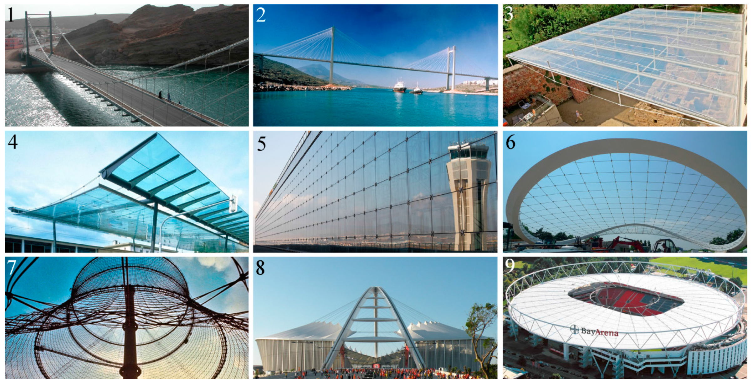
i.e., the span and the form of cable structures. For example, the availability of high-strength steel cables allows the construction of long-span cable structures like modern suspension bridges with spans of more than 1000 m; it also makes the construction of cable structures with new forms become reality, such as cable roofs and cable facades. Several typical modern cable structures with steel cables are shown in
Figure 1.
Figure 1.
Typical modern cable structures with steel cables: (1) suspension bridge, Highway Bridge Khor al Batah, Oman (photo credit: STRABAG); (2) cable-stayed bridge, Evripos Bridge, Greece (photo credit: schlaich bergermann und partner); (3) cable truss roof, Annex Lutherhaus Roof, Germany (photo credit: Monika Nikolic); (4) cable suspension roof, Glass Canopy of Station Plaza Heilbronn, Germany (photo credit: schlaich bergermann und partner); (5) cable net facade, Facade Airport Málaga, Spain (photo credit: Roschmann); (6) saddle-shaped cable net, Canopy in Autostadt Wolfsburg, Germany (photo credit: schlaich bergermann und partner); (7) cable net tower, Dry Cooling Tower in Schmehausen near Hamm, Germany (photo credit: schlaich bergermann und partner); (8) arch tower cable supported roof, Moses Mabhida Stadium, South Africa (photo credit: schlaich bergermann und partner); and (9) spoked wheel cable roof, Bay Arena Leverkusen, Germany (photo credit: Bayer 04 Leverkusen Fußball GmbH).
![Polymers 07 01501 g001]()
Carbon Fiber Reinforced Polymer (CFRP) is an advanced non-metallic composite material made of a polymer resin reinforced with carbon fibers [
5]. It has many superior performances, such as high strength, lightweight, no corrosion and high fatigue resistance. Thus, CFRP possess great potential to be made into cables and substitute for steel cables in cable structures, which may considerably promote their development.
In this paper, applying CFRP cables in cable structures is overviewed. First, characteristics of carbon fibers and polymer matrices are introduced. Second, forms and mechanical properties of CFRP cables are compared with those of a steel cable. Then, the existing CFRP cable structures worldwide are presented with photos and sketches, including their structural styles, geometries and design details; special attention is paid to the CFRP cable anchorages used in them. Furthermore, new applications of CFRP in cable structures, i.e., CFRP cable roofs and CFRP cable facades, are also introduced. Last but not least, other challenges except the anchoring that prevent CFRP cables from extensively using in cable structures, such as poor fire resistance and high unit price, are briefly introduced. Through the review of this paper, the state of the art and the future development of CFRP cable structures are clearly shown.
2. Composition of CFRP
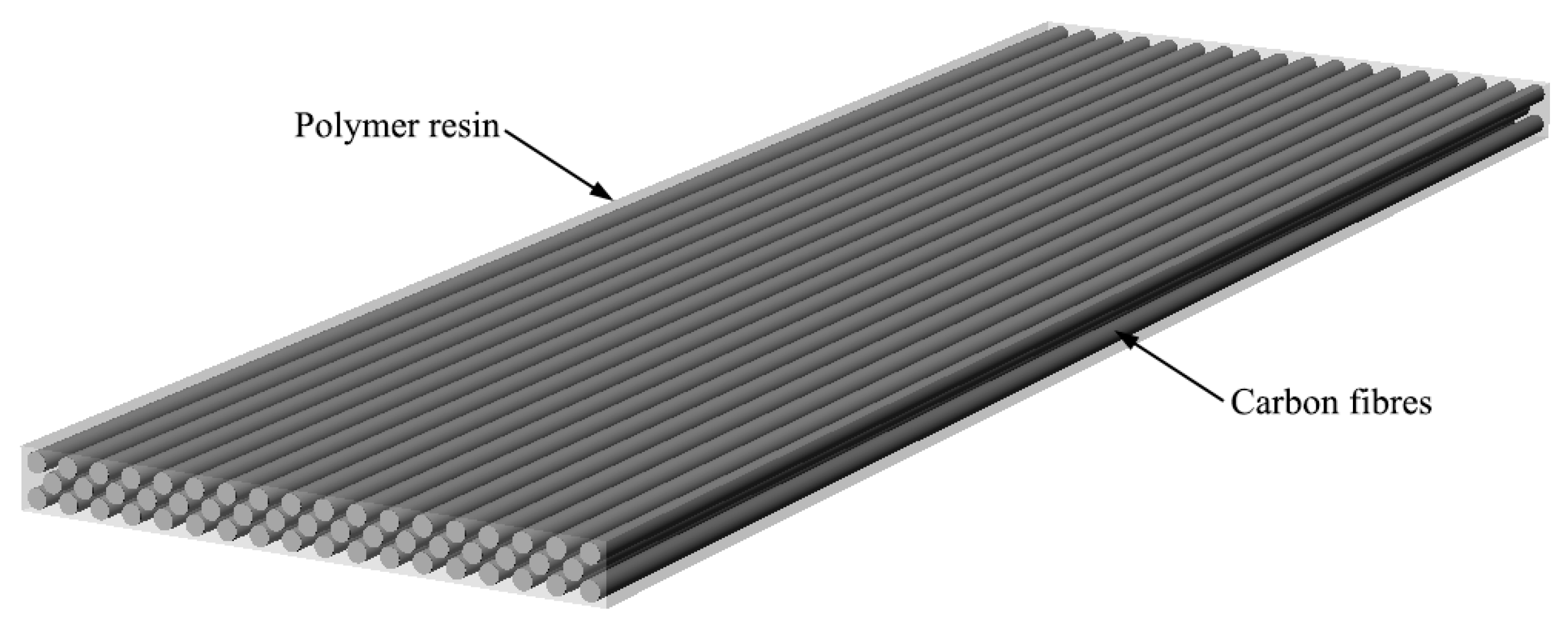
As the name suggests, Carbon Fiber Reinforced Polymer (CFRP) is composed of carbon fibers embedded in a polymer resin [
6], in which the carbon fibers function as the reinforcement material and the polymer resin functions as the matrix to hold the fibers. The typical structure of CFRP can be illustrated as
Figure 2.
Figure 2.
Typical structure of Carbon Fiber Reinforced Polymer (CFRP).
Figure 2.
Typical structure of Carbon Fiber Reinforced Polymer (CFRP).
2.1. Carbon Fibers
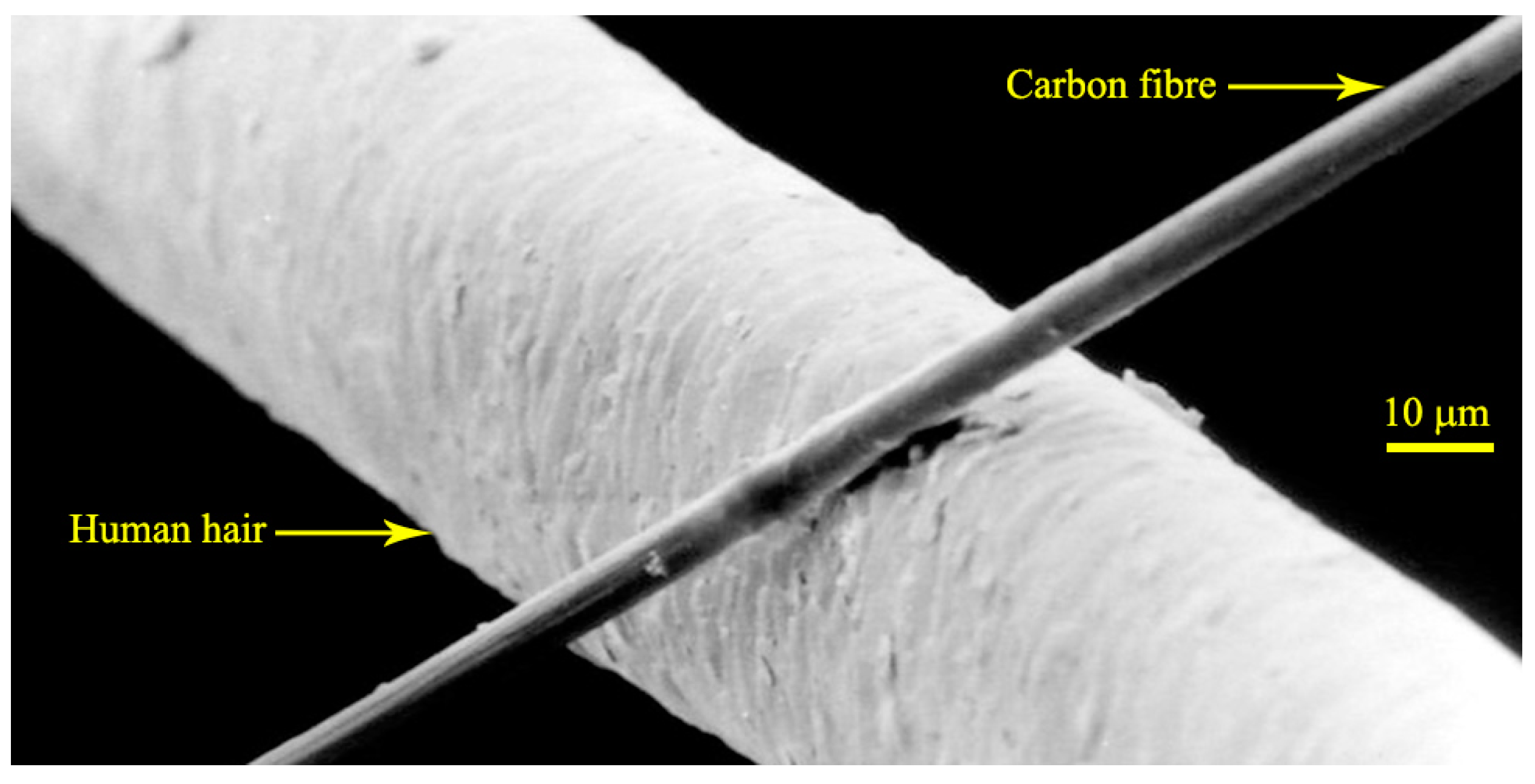
Carbon fibers refer to fibers which contain at least 90 weight % and up to 100 weight % carbon. They can be produced from polymeric precursor materials, such as polyacrylonitrile (PAN), cellulose, pitch and polyvinylchloride. These precursors are converted into carbon fibers through a series of treatment operations of heating and tensioning [
7].
From a macro perspective, carbon fibers are very thin filaments (about 5–10 μm in diameter), which are just visible to the human eye. The size of a carbon fiber is compared with that of a human hair in
Figure 3.
Figure 3.
Carbon fiber compared with human hair (photo credit: Anton).
Figure 3.
Carbon fiber compared with human hair (photo credit: Anton).
It is believed that the carbon fiber was invented by Thomas Edison as filaments for early light bulbs in 1879 [
8]. In the middle of the twentieth Century, high performance carbon fibers began to be manufactured [
9]. After decades of development, there are now a variety of carbon fibers with different strengths and moduli available on the market. The mechanical properties of three types of commonly used carbon fibers are listed in
Table 1, compared with two typical steel materials [
10,
11,
12].
Table 1.
Mechanical properties of carbon fibers compared with steel materials.
Table 1.
Mechanical properties of carbon fibers compared with steel materials.
| Material type | Density ρ (kg/m3) | Tensile Strength σu (GPa) | Elastic Modulus E (GPa) | Breaking Length σu/(ρg) (km) |
|---|
| Carbon fiber | Standard | 1760 | 3.53 | 230 | 205 |
| High strength | 1820 | 7.06 | 294 | 396 |
| High modulus | 1870 | 3.45 | 441 | 188 |
| Steel | S355 | 7850 | 0.50 | 210 | 6 |
| Wire | 7850 | 1.77 | 210 | 23 |
As shown in
Table 1, the tensile strengths of all carbon fibers are higher than those of steel materials, while their densities are much lower. The breaking length is a good parameter to show the high strength and lightweight characteristics of certain materials. It is defined as the maximum length of a hanging bar that could suspend its own weight and can be calculated by σ
u/(ρ
g), where
g is the standard gravity constant of 9.8 m/s
2. As can be seen from the table, the breaking lengths of carbon fibers are one order of magnitude larger than those of steel materials.
2.2. Polymer Resins
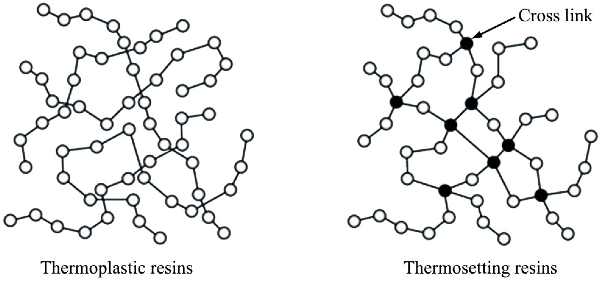
The polymer resins for CFRP are of two main types, namely, thermoplastic resin and thermosetting resin. This classification of polymers is based on their thermal (thermo-mechanical) response [
13].
Although thermoplastic and thermosetting resins sound similar, they have different molecular structures and thus having very different properties.
Thermoplastic resins are polymers linked by intermolecular interactions or van der Waals forces, forming a linear or branched molecular structure. This linear or branched molecular structure can only provide a relatively small restriction for the motion of molecular chains, which makes the thermoplastics remeltable and tractable upon the application of heat and pressure after curing [
14].
However, thermosetting resins are polymers joined together by chemical bonds, forming a highly cross-linked molecular structure. This cross-linked structure can greatly restrict the motion of molecular chains, which makes the thermosets unmeltable and intractable upon the application of heat after curing [
14].
The molecular structures of these two polymer resins are illustrated in
Figure 4 [
13].
Figure 4.
Molecular structures of thermoplastic resins and thermosetting resins.
Figure 4.
Molecular structures of thermoplastic resins and thermosetting resins.
The mechanical properties of several commonly used polymer resins are listed in
Table 2 [
10,
15].
Table 2.
Mechanical properties of commonly used polymer resins.
Table 2.
Mechanical properties of commonly used polymer resins.
| Type | Name | Density ρ (kg/m3) | Tensile Strength σu (GPa) | Elastic Modulus E (GPa) |
|---|
| Thermoplastic | Polyethersulfone | 1370 | 0.084 | 2.4 |
| Polyetherether ketone | 1310 | 0.070 | 3.8 |
| Polyetherimide | 1270 | 0.105 | 3.0 |
| Thermosetting | Orthophthalic polyester | 1350 | 0.070 | 3.2 |
| Vinylester | 1250 | 0.075 | 3.3 |
| Epoxy | 1250 | 0.115 | 3.0 |
Comparing
Table 1 and
Table 2, it can be seen that the densities of polymer resins are slightly smaller than those of carbon fibers, while the strengths and moduli of carbon fibers are orders of magnitude greater than those of polymer resins. However, due to the filamentary nature of carbon fibers, they cannot be applied as independent engineering materials and have to be used in the synergistic fashion with a polymer resin to realize their superior mechanical properties.
The differences of strength and modulus between the carbon fiber and the polymer resin make CFRP a typical orthotropic material. In the fiber direction, CFRP mainly exhibits the mechanical properties of the carbon fiber, i.e., relatively high strength and high modulus. But in the direction perpendicular to the fiber axis, CFRP mainly exhibits the mechanical properties of the polymer resin, i.e., relatively low strength and low modulus. This strong orthotropy causes CFRP cables difficult to be anchored.
3. CFRP Cables
CFRP was first manufactured and used in aeronautics and astronautics industries about 50 years ago, shortly after the invention of high performance carbon fibers [
16]. In the construction industry, the first practical utilization of CFRP was in 1991 for strengthening the Ibach Bridge in Lucerne, Switzerland [
8]. From then on, more and more CFRP products were used, not only in strengthening, repairing, reinforcing, pre-stressing, but also as cables in cable structures.
Usually, unidirectional CFRP materials are used to manufacture CFRP cables. The mechanical properties along the fiber direction of CFRPs, such as the tensile strength σu and the elastic modulus E, are usually approximately 60% of those of the carbon fibers because the fiber volume fraction is usually 60%. It should also be noted that σu and E of CFRP cables are slightly smaller than those of the corresponding CFRP; this is similar to the fact that σu and E of steel cables are slightly smaller than those of steel wires.
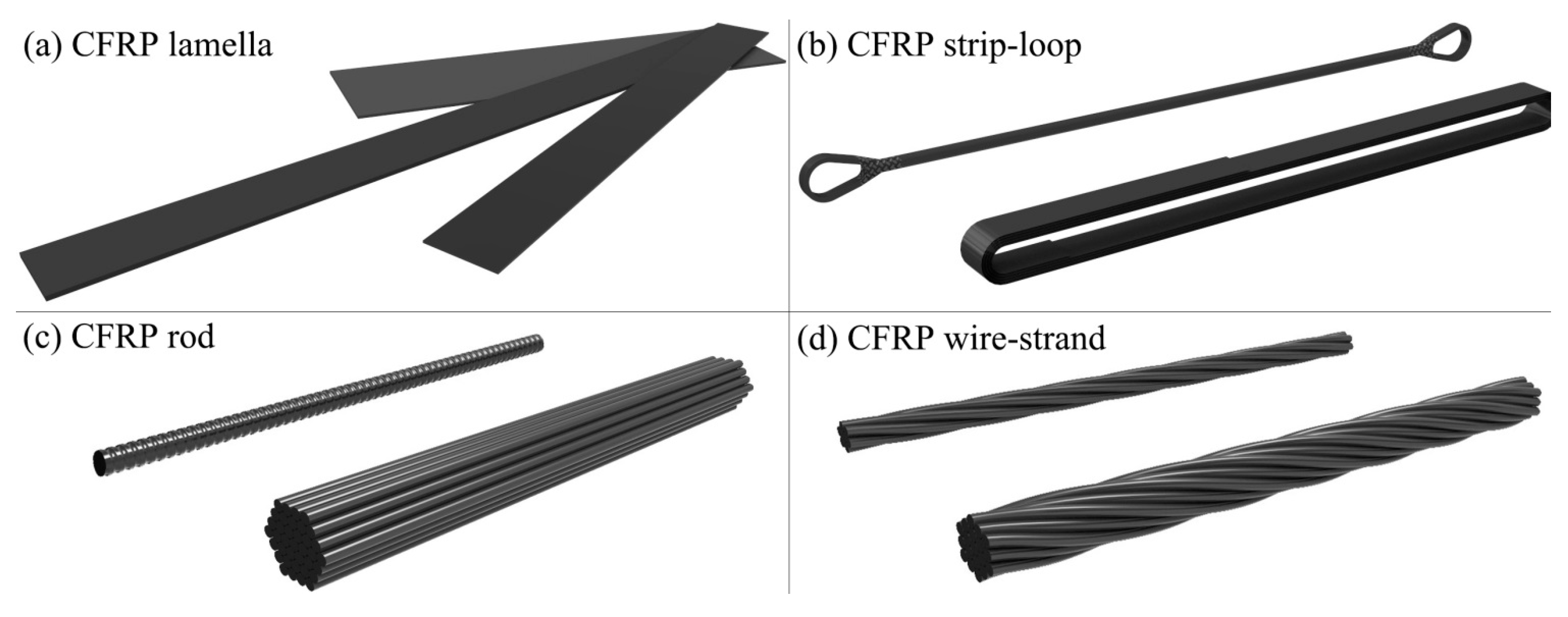
According to the different structural forms, the existing CFRP cables can be classified into four main types, which are shown in
Figure 5.
Figure 5.
Four main types of CFRP cables: (a) the CFRP cable in the form of lamella, which can be fabricated by pultrusion or lamination; (b) the CFRP cable in the form of rod, which is usually fabricated by pultrusion; such CFRP cable can be made up of a single rod or a rod bundle, and the CFRP rod can be plain round or deformed; (c) the CFRP cable in the form of strip-loop, which is fabricated by winding a continuous CFRP strip on two pins; then the strip-loop can choose to be laminated or non-laminated; and (d) the CFRP cable in the form of wire-strand which is fabricated by twisting several CFRP wires into a helix. The CFRP wires used are usually produced by pullwinding.
The mechanical properties of four CFRP cables in different forms are compared with those of a steel full-locked coil rope in
Table 3 [
14,
17,
18,
19,
20].
The above four CFRP cables are all made from standard carbon fibers (see
Table 1) with an approximate 60% fiber volume. The steel full-locked coil rope is a commonly used cable type in modern cable structures. As seen from
Table 3, the tensile strengths of CFRP cables are higher than that of steel cable while their densities are only approximately 1/5 of the steel cable’s density.
Table 3.
Mechanical properties of CFRP cables compared with steel cable.
In addition to high strengths and low weights, CFRP cables have better corrosion and fatigue resistance and lower thermal expansion than steel cables. Furthermore, because carbon fibers have excellent creep resistance, the stress relaxation of CFRP cables is very small and there is no need to limit sustained tensile stresses [
10].
Aside the advantages mentioned above, CFRP cables also have some disadvantages; these include lower elastic modulus than that of steel cables (see
Table 3), difficult to be anchored and relatively high cost, which may have negative effects on the application of CFRP cables.
4. Existing CFRP Cable Structures
Due to the aforementioned high performance, CFRP has been considered for cables and used in cable structures since 1982 [
21]. In 1987, Professor Meier of EMPA proposed the conception of building a CFRP cable-stayed bridge with a main span of 8400 m crossing the Strait of Gibraltar [
22].
The first use of CFRP cables in a real cable structure dates back to 1996 [
23]. From then to now, there have been ten CFRP cable structures over the world, even though all of them were built more or less experimentally. The existing CFRP cable structures are listed and introduced as follows.
4.1. Tsukuba FRP Bridge
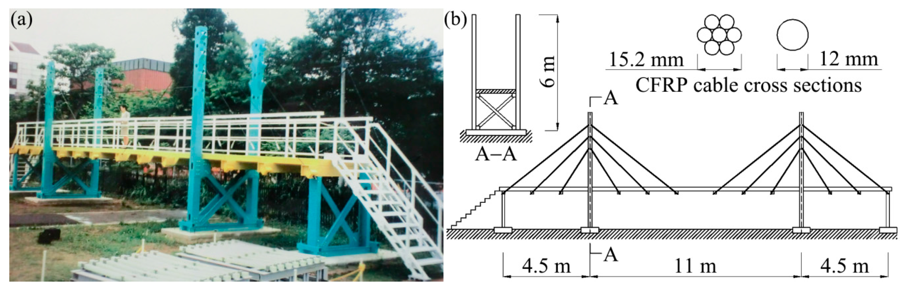
The Tsukuba FRP Bridge, to the author’s knowledge, is the first CFRP cable structure in the world. Moreover, it is also a full FRP structure. This structure, located in Ibaraki, Japan, was designed by Public Works Research Institute in Tsukuba and completed in March 1996. The photo and sketch of Tsukuba FRP Bridge are shown in
Figure 6 [
23].
Figure 6.
Tsukuba FRP Bridge, (a) photo (photo credit: Iwao Sasaki) and (b) sketch.
Figure 6.
Tsukuba FRP Bridge, (a) photo (photo credit: Iwao Sasaki) and (b) sketch.
The Tsukuba Bridge is a pedestrian cable-stayed bridge with three spans (see
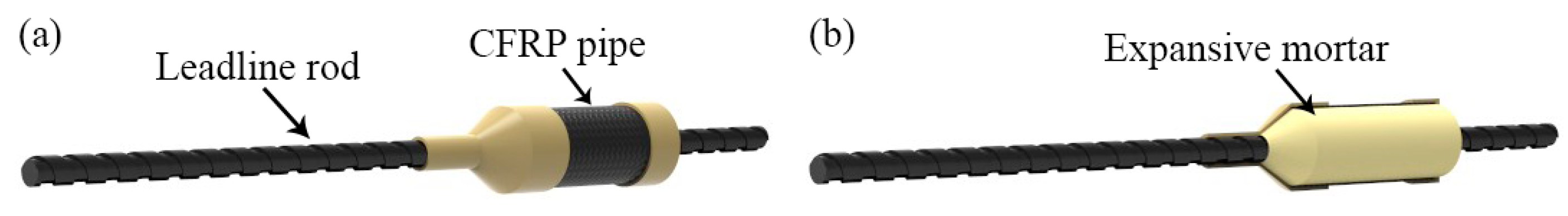
Figure 6). The main span between pylons is 11.0 m, while two side spans are 4.5 m. In this bridge, the pylons are made of GFRP, the deck is a GFRP profile strengthened by CFRP lamellas and all the 24 stay cables are made of CFRP. Specifically, two types of CFRP cables were used in this bridge, which are indented Leadline rods from Mitsubishi Chemical Company and CFCC 7-wire tendons from Tokyo Rope Manufacturing Co., Ltd. (Tokyo, Japan). A tailor-made anchorage composed of CFRP pipe and expansive mortar was designed to anchor these CFRP stay cables. The diagrams of this anchorage are shown in
Figure 7 [
23].
Figure 7.
Anchorage system used in Tsukuba FRP Bridge, (a) full view and (b) transparent view.
Figure 7.
Anchorage system used in Tsukuba FRP Bridge, (a) full view and (b) transparent view.
The CFRP cable shown in the above figure is the indented Leadline rod. The anchorage for the CFCC 7-wire tendon is exactly the same. In this anchorage system, a CFRP pipe is used as the anchorage socket and an expansive mortar is adopted to generate enough bond force to anchor the CFRP cable.
4.2. Stork Bridge
The Stork Bridge is the first highway cable-stayed bridge with CFRP cables in the world. This bridge is located in Winterthur, Switzerland, and was designed by OMG and Partner Architects AG and Höltschi & Schurter AG. After one and a half years of construction, this bridge was completed and opened to traffic on 27 October 1996. The photo and sketch of Stork Bridge are shown in
Figure 8 [
24].
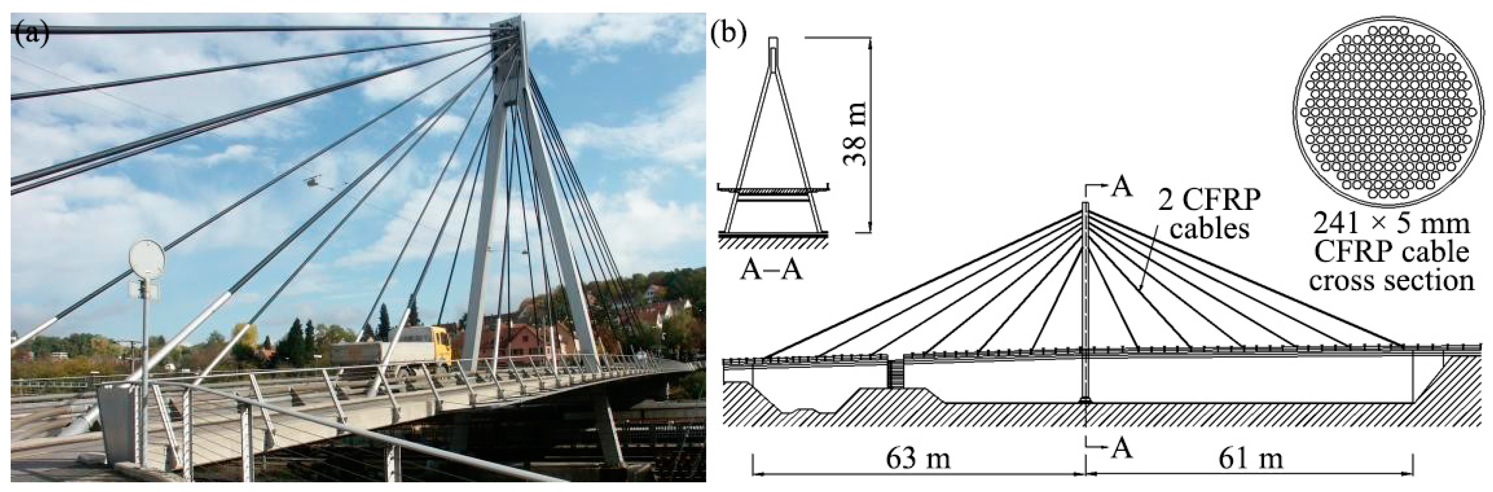
Figure 8.
Stork Bridge, (a) photo (photo credit: EMPA) and (b) sketch.
Figure 8.
Stork Bridge, (a) photo (photo credit: EMPA) and (b) sketch.
The Stork Bridge is a single pylon cable stayed bridge with double cable planes (see
Figure 8). It has 24 stay cables. Two of them are CFRP cables, while others are normal steel cables. These two CFRP cables are 35 m long parallel rod bundles. Each bundle consists of 241 CFRP rods of Φ 5 mm. The load bearing capacity of each cable is 12 MN. In order to carry such a large force, a special anchorage called Gradient Anchorage System was developed by EMPA. The diagrams of this anchorage are shown in
Figure 9 [
25].
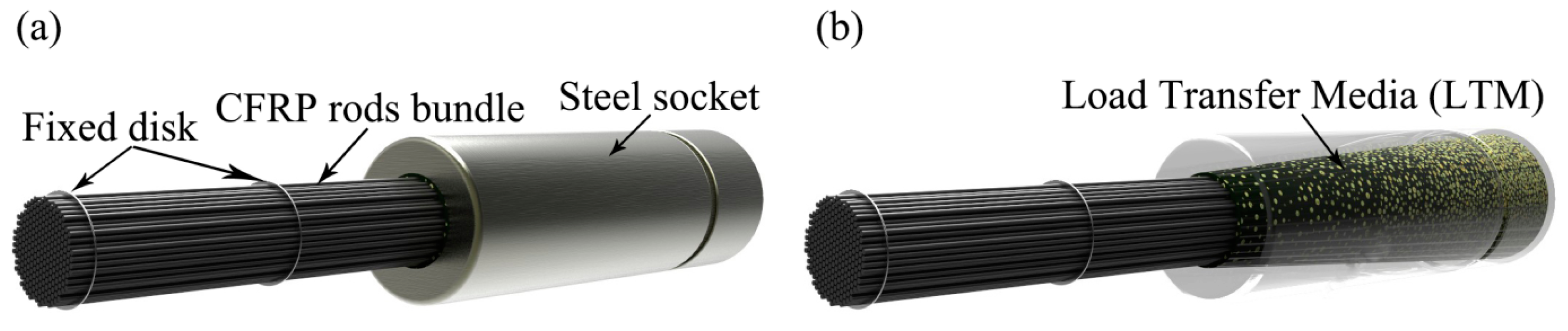
Figure 9.
Gradient Anchorage System, (a) full view and (b) transparent view.
Figure 9.
Gradient Anchorage System, (a) full view and (b) transparent view.
The above anchorage is composed of a conical steel socket and a mortar called Load Transfer Media (LTM), which was manufactured by mixing Al
2O
3 ceramic granules of approximately Φ 2 mm (light yellow particles in
Figure 9b) into the epoxy resin (the dark cone in the
Figure 9b). From the mouth of the steel socket to its end, the distribution density of granules in the resin increases gradually, so as to achieve an anchorage mortar with gradient elastic modulus. The principle of this anchorage is illustrated in
Figure 10, compared with normal conical mortar anchorage [
25].
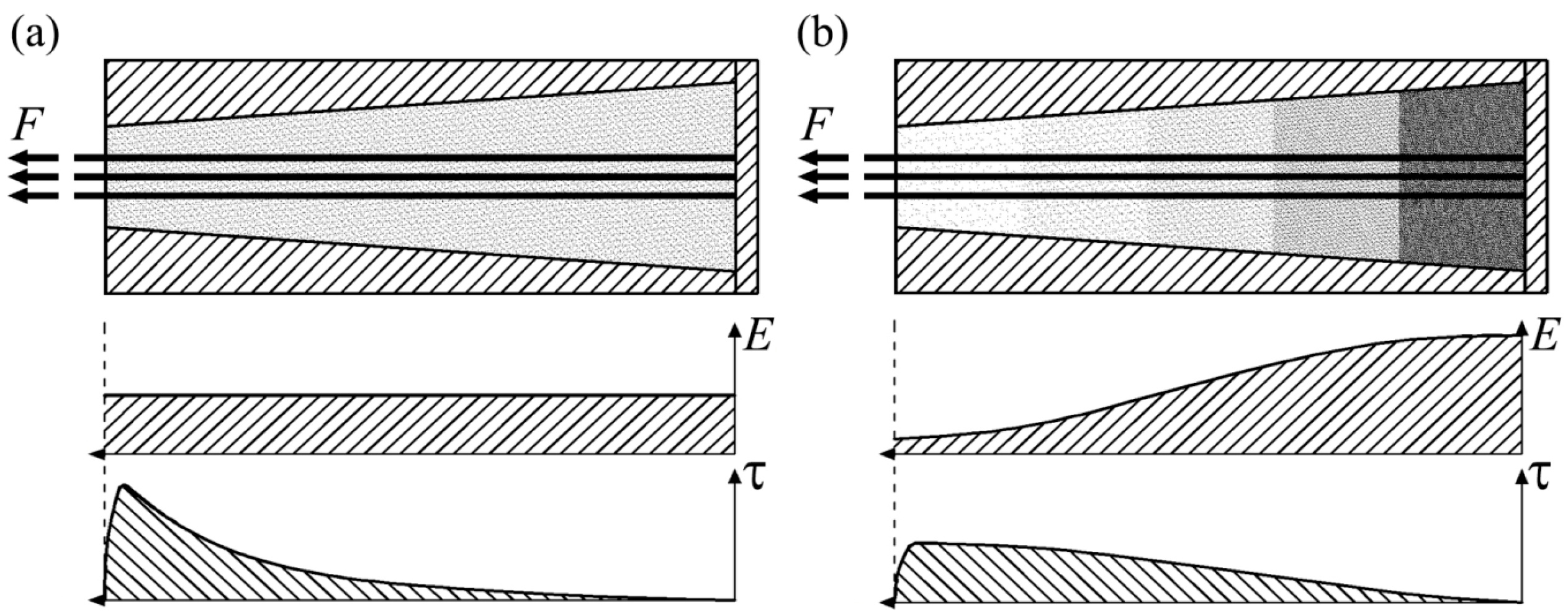
Figure 10.
Principle of Gradient Anchorage System: (a) normal conical mortar anchorage and (b) Gradient Anchorage System.
Figure 10.
Principle of Gradient Anchorage System: (a) normal conical mortar anchorage and (b) Gradient Anchorage System.
In the normal conical mortar anchorage, the elastic modulus of the anchorage mortar is constant. This will cause severe shear stress concentration of CFRP rods at the mouth of anchorage socket (see
Figure 10a). However, due to the gradually increased elastic modulus of mortar from the socket mouth to the socket end, the stress peak of CFRP rods can be considerably reduced in the Gradient Anchorage System (see
Figure 10b). Hence the anchorage efficiency will be highly improved [
25].
Before applying this CFRP cable anchorage system into the Stork Bridge, series of tests and analysis were operated in EMPA. Both experimental and theoretical results demonstrated that the anchorage efficiency of the Gradient Anchorage System is higher than 92% [
24].
4.3. Neigles CFRP Footbridge
The Neigles CFRP Footbridge is the first suspension bridge with CFRP cables in the world. This bridge is over the La Sarine River and located in Fribourg, Switzerland. The initial Neigles footbridge was constructed with steel cables. However, due to the severe corrosion, the steel main cables were removed and replaced with CFRP cables in November 1998. The photo and sketch of Neigles CFRP footbridge are shown in
Figure 11 [
26,
27].
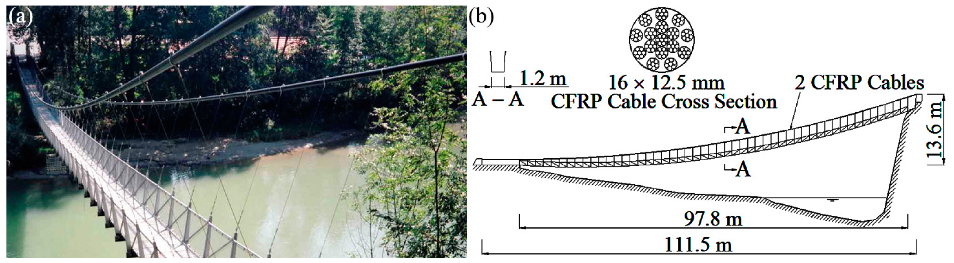
Figure 11.
Neigles CFRP footbridge, (a) photo (photo credit: Tokyo Rope) and (b) sketch.
Figure 11.
Neigles CFRP footbridge, (a) photo (photo credit: Tokyo Rope) and (b) sketch.
The Neigles CFRP Footbridge is a pedestrian suspension bridge with a single span (see
Figure 11). It has two CFRP main cables, which were manufactured by the Tokyo Rope Manufacturing Co., Ltd. Each cable consists of 16 parallel CFCC 7-wire strands and its load bearing capacity is 2272 kN. These cables are protected by the polyethylene sheaths and anchored by the Multiple Resin Filling Anchorage System. The diagrams of this anchorage system are shown in
Figure 12 [
23,
26].
Figure 12.
Multiple Resin Filling Anchorage System, (a) full view and (b) transparent view.
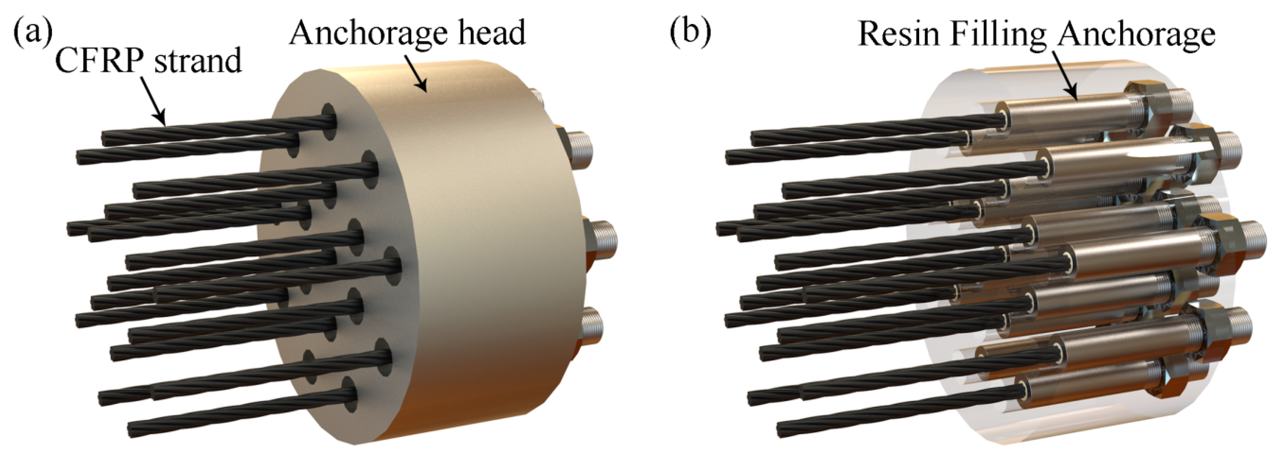
Figure 12.
Multiple Resin Filling Anchorage System, (a) full view and (b) transparent view.
This anchorage system consists of an anchorage head and 16 Resin Filling Anchorages. Each CFCC 7-wire strand is anchored by a Resin Filling Anchorage, which is an anchorage developed by the Tokyo Rope for the CFCC strands. In this anchorage, the strand is bonded to the terminal using a special resin with an anchorage length of approximately 13.5 times the strand diameter [
23]. The Resin Filling Anchorages have not only been used in this bridge but also in many other projects including the following Herning CFRP Bridge (see
Section 4.4).
4.4. Herning CFRP Bridge
The Herning CFRP Bridge is a pedestrian overpass across a railway switchyard in the vicinity of Herning, Denmark. This bridge was designed by COWI A/S and completed in June 1999. The photo and sketch of Herning CFRP Footbridge are shown in
Figure 13 [
28].
Figure 13.
Herning CFRP Bridge, (a) photo (photo credit: COWI) and (b) sketch.
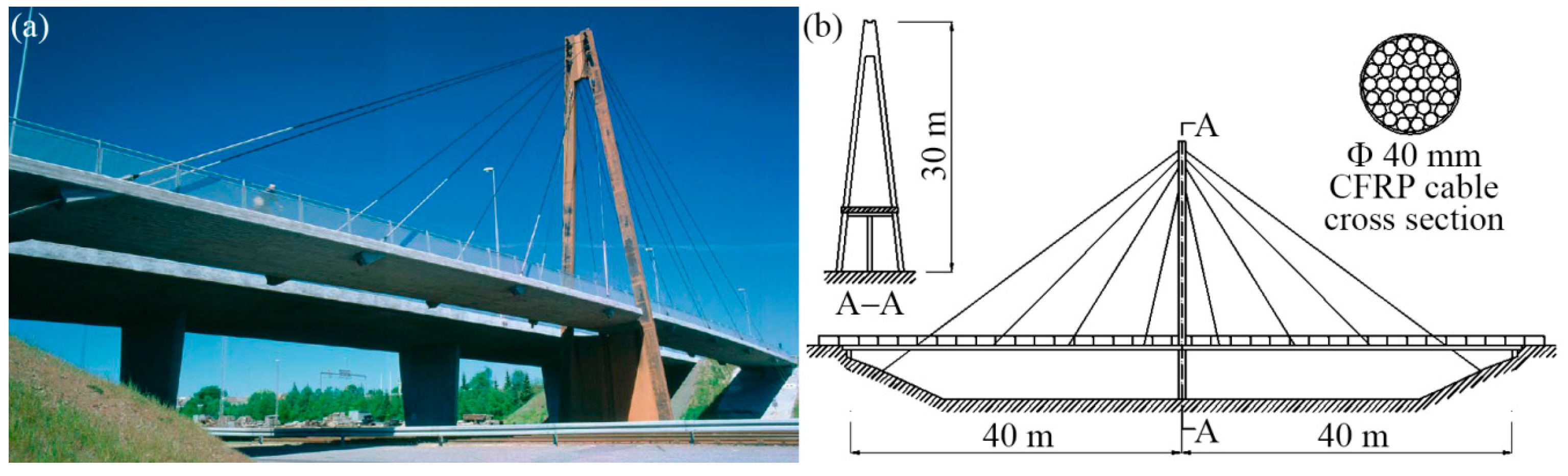
Figure 13.
Herning CFRP Bridge, (a) photo (photo credit: COWI) and (b) sketch.
The Herning Footbridge is a single pylon cable stayed bridge with double cable planes (see
Figure 13). It has 16 stay cables in total and all of them are CFRP cables. These CFRP cables are CFCC 37-wire strands produced by the Tokyo Rope Manufacturing Co. Ltd. with a diameter of 40 mm. The load bearing capacity of each cable is 1070 kN and all cables were supplied from factory in fixed lengths with Resin Filling Anchorages. The diagrams of this anchorage are shown in
Figure 14 [
28].
Figure 14.
Resin Filling Anchorage, (a) full view and (b) transparent view.
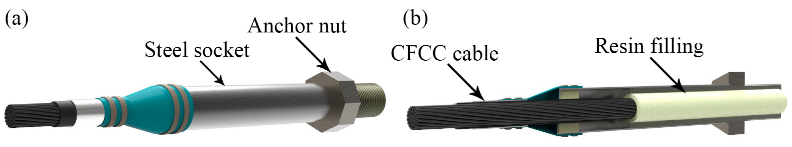
Figure 14.
Resin Filling Anchorage, (a) full view and (b) transparent view.
The above anchorage system is mainly composed of a straight tube shaped steel socket and a special resin filling. The anchorage length is approximately 13.5 times that of the cable diameter. The anchor nut is set at the rear of the steel socket to connect the anchorage to the other parts of the bridge [
28].
This anchorage is very similar to the Resin Filling Anchorage applied in the Neigles CFRP Footbridge (see
Section 4.3). The only difference is that this anchorage has a larger size and is used to anchor bigger CFCC strand with more wires.
4.5. Laroin CFRP Footbridge
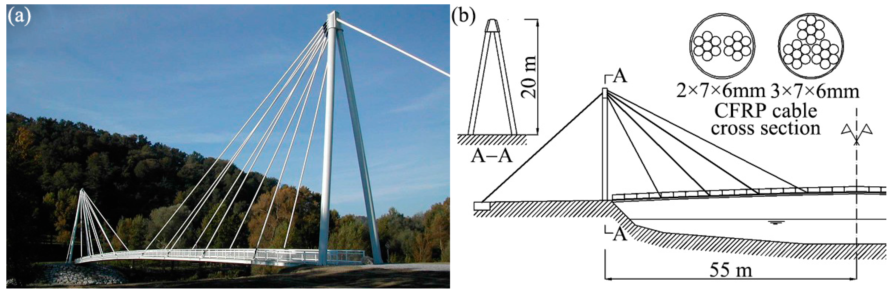
The Laroin CFRP Footbridge crosses the Gave du Pau River and is located in Laroin, France. This bridge was designed by Freyssinet International and completed in 2002. The photo and sketch of Laroin CFRP Footbridge are shown in
Figure 15 [
29].
Figure 15.
Laroin CFRP Footbridge, (a) photo (photo credit: Freyssinet) and (b) sketch.
Figure 15.
Laroin CFRP Footbridge, (a) photo (photo credit: Freyssinet) and (b) sketch.
The Laroin CFRP Footbridge is a single span cable stayed bridge with twin towers and double cable planes (see
Figure 15). The main span of 110 m long and 2.5 m wide is supported by eight pairs of CFRP stay cables. The back stays, which are standard steel cables, were anchored to the concrete anchor blocks in the ground. These 16 CFRP cables, from 20 m to 45 m long, are modular and each module is composed of a CFRP parallel 7-rod bundle. According to the different load conditions, the four pairs of cables near the pylons contain two modules (
i.e., two 7-rod bundles), while the other four pairs near the middle span contain three modules (
i.e., three 7-rod bundles). The CFRP rods, which were produced by SOFICAR, have a diameter of 6 mm and a load bearing capacity of 70 kN. In order to anchor these CFRP cables, a patented anchorage system called Modular Clamp Anchorage was developed by Freyssinet. The diagrams of this anchorage (one module) are illustrated as follows [
29].
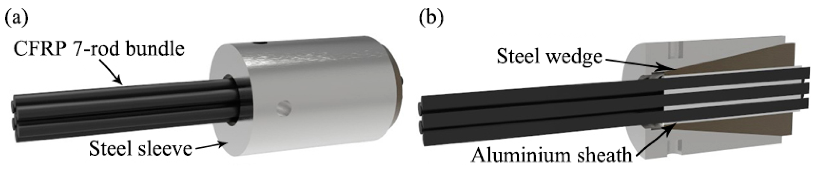
Figure 16 shows one module of the Modular Clamp Anchorage system. In this figure, one module of CFRP cable,
i.e., one CFRP 7-rod bundle, is gripped as a group by the wedge type anchorage. In order to prevent the transversal damage of CFRP from directly clamping, every wire is protected by an aluminum sheath. Each anchorage shown above is a module and each end of CFRP cables contains two or three these modular anchorages [
29].
Figure 16.
Modular Clamp Anchorage (one module), (a) full view and (b) sectional view.
Figure 16.
Modular Clamp Anchorage (one module), (a) full view and (b) sectional view.
There are two main advantages of applying the modular cable and the modular anchorage. Firstly, a bundle of CFRP wires are anchored integrally in a module, instead of, respectively, anchoring. This can make the anchorage compact and reduce the size. Secondly, unlike conventional CFRP cable anchorages, which are unique, this type of anchorage is assembled by individual modules, which are standard. Because every module has already been maturely researched, the anchorages for different cable sizes do not need to be investigated any more but simply assembled by several modules. This can facilitate the anchorage design and reduce the cost [
29].
4.6. Jiangsu University CFRP Footbridge
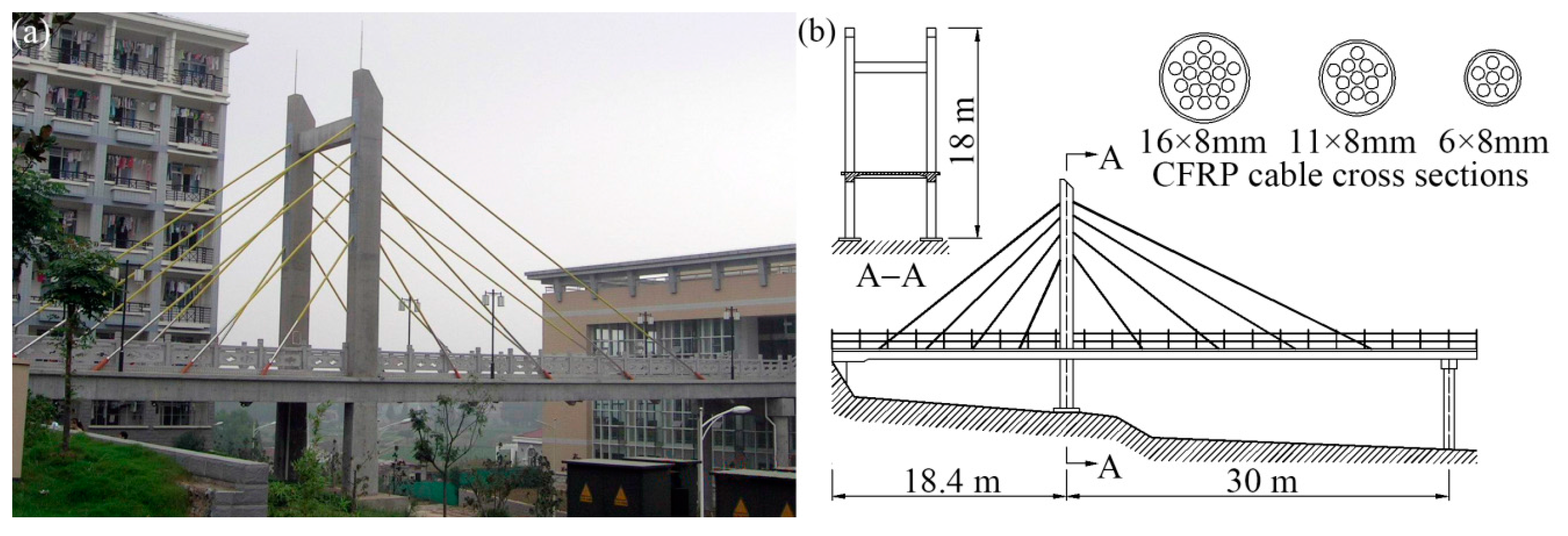
The Jiangsu University CFRP Footbridge is a cable-stayed bridge located in Zhenjiang, China. It was designed by Southeast University, Jiangsu University and Peking TXD Technology Company. After one year’s construction, this bridge was completed in the end of May 2005. The photo and sketch of this bridge are shown in
Figure 17 [
30].
Figure 17.
Jiangsu University CFRP Footbridge, (a) photo (photo credit: Kuihua Mei) and (b) sketch.
Figure 17.
Jiangsu University CFRP Footbridge, (a) photo (photo credit: Kuihua Mei) and (b) sketch.
The Jiangsu University CFRP Footbridge is a single pylon cable-stayed bridge with double cable planes (see
Figure 17). All 16 stay cables are made of CFRP parallel rod bundles. The adopted CFRP bars are Φ 8 mm Leadline indented rods produced by Mitsubishi Chemical Company. Based on the different load-bearing requirements, three kinds of cables with different number of bars were applied (see
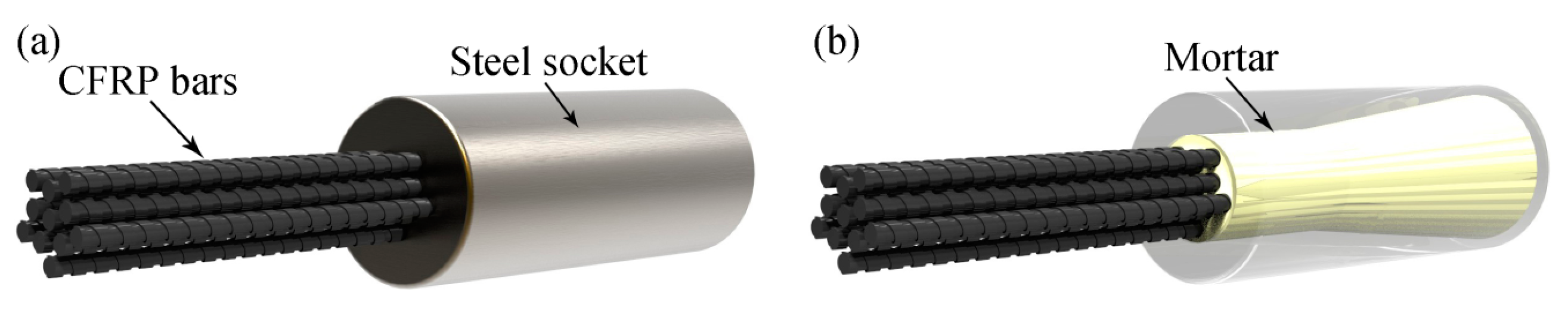
Figure 17). The load bearing capacities of these cables are 720 kN (6 × 8 mm), 1320 kN (11 × 8 mm) and 1920 kN (16 × 8 mm), respectively. The CFRP cable anchorage was specially designed, which is called the Straight Tube and Inner Cone Anchorage. The diagrams of this anchorage are shown in
Figure 18 [
30,
31].
Figure 18.
Straight Tube and Inner Cone Anchorage, (a) full view and (b) transparent view.
Figure 18.
Straight Tube and Inner Cone Anchorage, (a) full view and (b) transparent view.
This anchorage consists of a steel socket and the mortar (epoxy resin or expansive cement) inside. The shape of the socket is particularly designed. The front part near the mouth is a straight tube while the rear part is a cone. This design has the advantages of straight tube anchorage and conical anchorage combined. The principle of this anchorage is illustrated in
Figure 19, compared with normal conical anchorage [
31].
Figure 19.
Principle of Straight Tube and Inner Cone Anchorage: (a) normal conical anchorage and (b) Straight Tube and Inner Cone Anchorage.
Figure 19.
Principle of Straight Tube and Inner Cone Anchorage: (a) normal conical anchorage and (b) Straight Tube and Inner Cone Anchorage.
The normal conical anchorage can effectively restrict the creep, but severe stress concentration of shear and radial stress of CFRP rods will occur at the socket mouth (see
Figure 19a). However, in the Straight Tube and Inner Cone Anchorage (see
Figure 19b), both the shear and radial stress peaks of CFRP rods will start near the joint of the straight tube and cone and go on constantly to the socket mouth. In this way, the magnitudes of stress peaks are greatly reduced. Therefore, both the creep restriction and the anchorage efficiency improvement are achieved at the same time [
31].
4.7. Penobscot Narrows Bridge
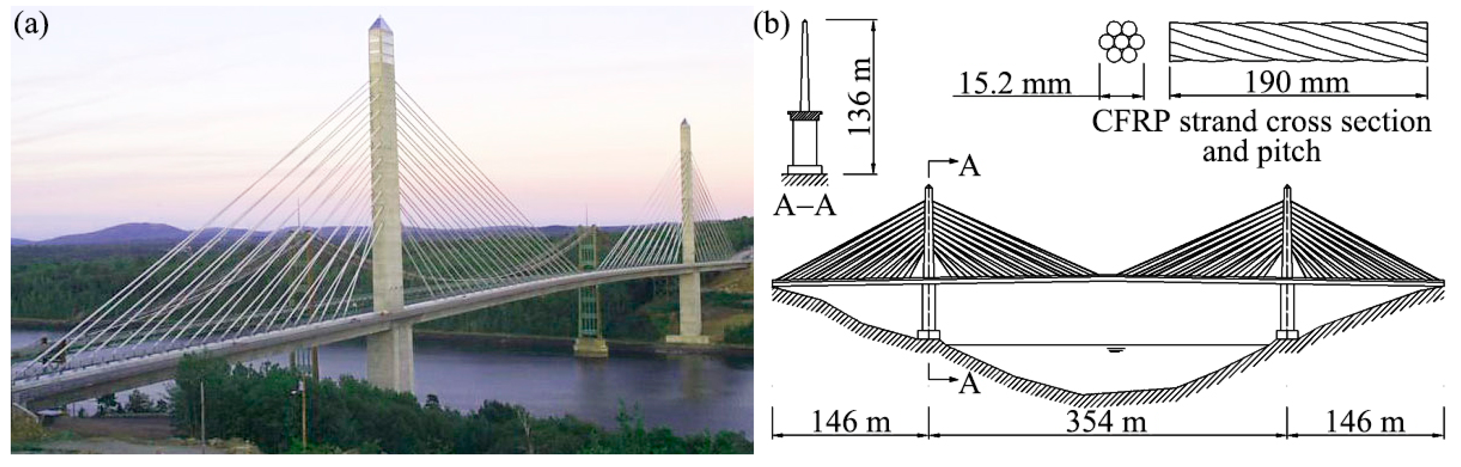
The Penobscot Narrows Bridge is the first cable-stayed bridge in America, which adopts CFRP strands in stay cables. This bridge, owned by Maine Department of Transportation, is located in Penobscot, ME, USA. The designer of this bridge was FIGG Engineering Group and its constructor was Cianbro/Reed & Reed, LLC (Bucksport, ME, USA). After three years of construction, this bridge was completed and opened to the traffic on 30 December 2006. After half year of completion, six steel strands in different stay cables were removed and replaced with six CFRP strands. The Penobscot Narrows Bridge’s photo and sketch are shown below [
32].
The Penobscot Narrows Bridge is a twin masts cable-stayed bridge with single cable plane (see
Figure 20). Its span is 146 m + 354 m + 146 m and the mast height is 136 m. It has 40 stay cables, which are all parallel 7-wire strand cables. These cables were not anchored at the mast but go through cradles in the mast and anchored at the bridge deck. From the total of 40 cables, three cables with different lengths (approximately 86 m, 198 m and 300 m, respectively) through the western pylon were selected to install CFRP stands. In every selected cable, two steel strands were uninstalled and two new CFRP strands were mounted at the same place. These six CFRP strands are all CFCC 1 × 7 strands, produced by Tokyo Rope Manufacturing Co., Ltd. Based on the existing Resin Filling Anchorage for CFCC strands, the design team of Penobscot Narrows Bridge, who cooperated with Lawrence Technological University, developed a new kind of anchorage for this case. This anchorage can be named as “Highly Expansive Material Filling Anchorage”, which is illustrated in
Figure 21 [
32].
Figure 20.
Penobscot Narrows Bridge, (a) photo (photo credit: MOT) and (b) sketch.
Figure 20.
Penobscot Narrows Bridge, (a) photo (photo credit: MOT) and (b) sketch.
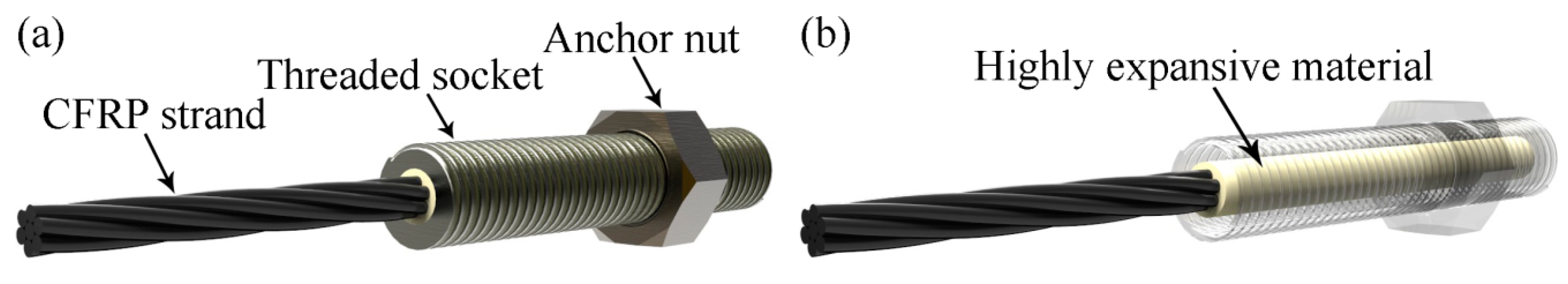
Figure 21.
Highly Expansive Material Filling Anchorage, (a) full view and (b) transparent view.
Figure 21.
Highly Expansive Material Filling Anchorage, (a) full view and (b) transparent view.
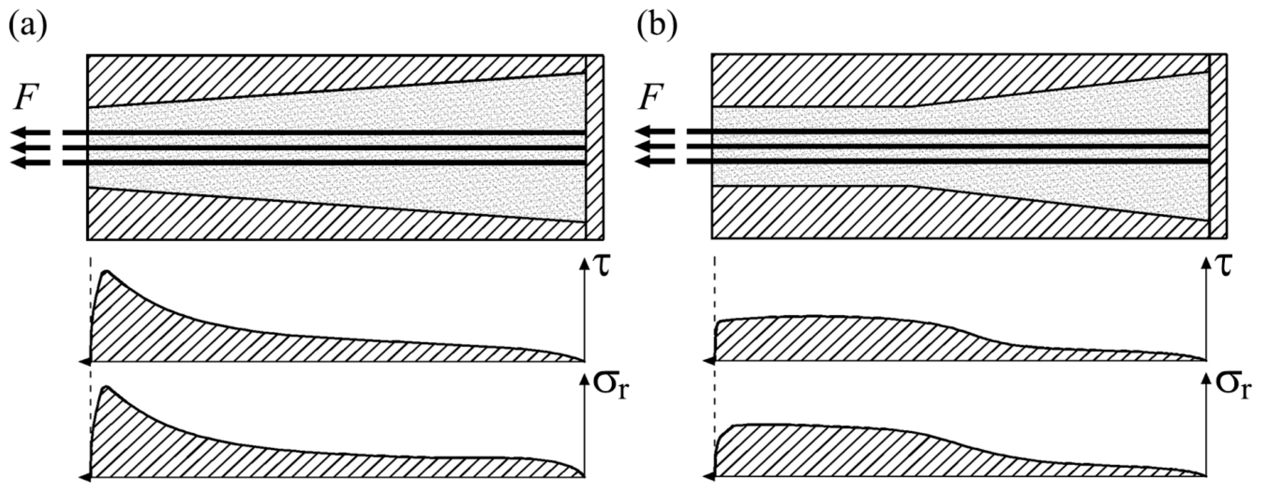
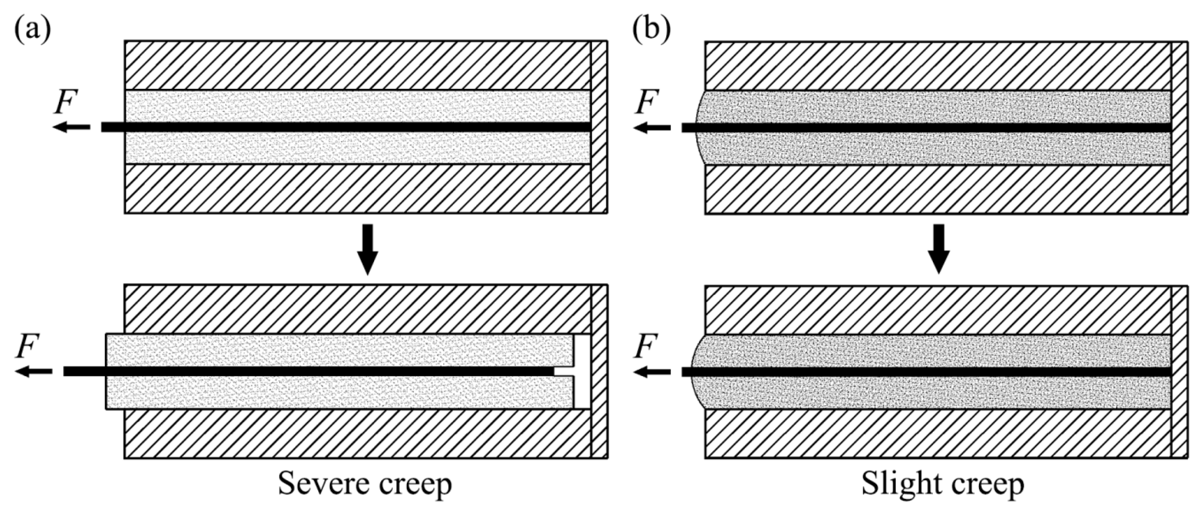
This anchorage consists of a long threaded socket with a hollow straight tube and mortar inside. Outside the socket, there is an anchor nut for fixing this anchorage to the structure. The inner diameter of this hollow socket is slightly bigger than the diameter of the strand. The space between the strand and the socket wall is filled by a cement-based mortar, called Highly Expansive Material (abbreviated as HEM). Through expansion during curing, the HEM will produce enough radial pressure (approximately 75.8 MPa in this case) after hardening, so as to hold the CFRP strand. The advantage of the Highly Expansive Material (HEM) Filling Anchorage is illustrated in
Figure 22, compared with a straight tube anchorage with normal mortar [
32].
Figure 22.
Principle of Highly Expansive Material Filling Anchorage: (a) straight tube anchorage with normal mortar and (b) Highly Expansive Material Filling Anchorage.
Figure 22.
Principle of Highly Expansive Material Filling Anchorage: (a) straight tube anchorage with normal mortar and (b) Highly Expansive Material Filling Anchorage.
The socket of the Highly Expansive Material Filling Anchorage is a straight tube. This can relieve the stress concentration near the anchorage mouth, but may lead to severe creep if the normal mortar is used (see
Figure 22a). However, the creep coefficient of HEM is much smaller than that of normal epoxy-based mortar. It can help the anchorage successfully avoid the severe creep (see
Figure 22b) [
32].
4.8. EMPA Bowstring Arch Footbridge
The EMPA Bowstring Arch Footbridge is a pedestrian bridge over a small pond at Swiss Federal Laboratories for Materials Science and Technology (EMPA). It is located in Dübendorf near Zürich, Switzerland. This bridge was designed by researchers of EMPA and was installed in spring 2007. The photo and sketch of EMPA Bowstring Arch Footbridge are shown in
Figure 23 [
33].
Figure 23.
EMPA Bowstring Arch Footbridge, (a) photo (photo credit: Urs Meier) and (b) sketch.
Figure 23.
EMPA Bowstring Arch Footbridge, (a) photo (photo credit: Urs Meier) and (b) sketch.
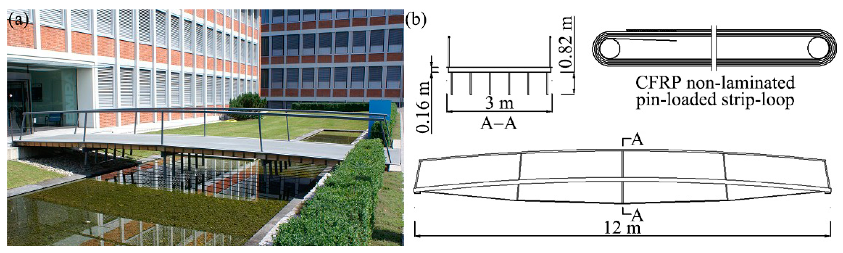
The EMPA Bowstring Arch Footbridge is a bowstring arch bridge with a span of 12 m and a width of 3 m (see
Figure 23). The bridge deck is mainly made of Swiss grown Norway spruce (Picea abies), which was laterally strengthened by CFRP strips. In the longitudinal direction, six CFRP non-laminated strip-loop cables were arranged under the deck and evenly distributed over its width to serve as bowstrings. Each cable is 30 mm wide and its nominal cross section is 60 mm
2. The CFRP cable and pin-loaded anchorage are shown in
Figure 24 [
33].
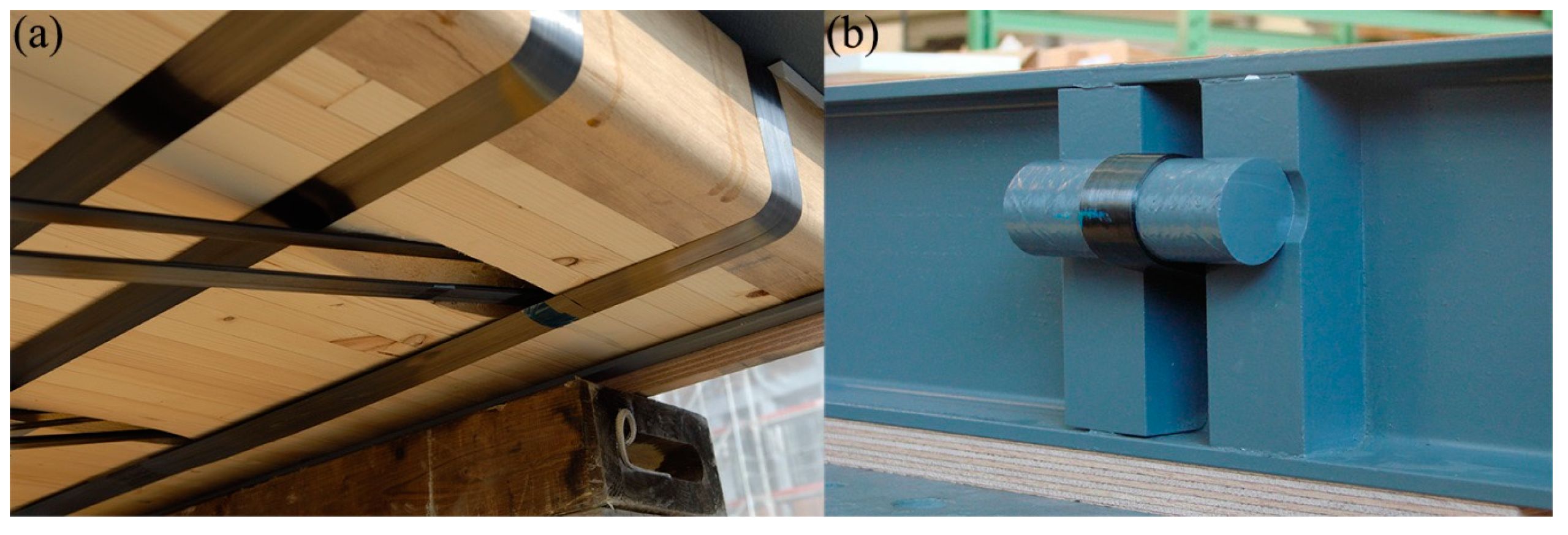
Figure 24.
(a) CFRP non-laminated strip-loop cable and (b) pin-loaded anchorage (photo credit: Urs Meier).
Figure 24.
(a) CFRP non-laminated strip-loop cable and (b) pin-loaded anchorage (photo credit: Urs Meier).
The CFRP cable used is a non-laminated pin-loaded strip-loop (see
Figure 23b). Such cable, supplied by Carbo-Link GmbH, Switzerland, is manufactured by continuously winding a very thin (approximately 0.1 mm thick) CFRP strip around two round pins (the pins are made of GFRP in this case). After winding, only the end of the outermost layer is bonded to the next outermost layer through fusion to form a closed loop (thermoplastics matrix is adopted to produce the CFRP strip). Compared with the laminated strip-loop, the shear and radial stresses at the anchorage zone (especially the layer contacting the pin) of the non-laminated strip-loop will distribute more uniformly, because different layers of the non-laminated one can mutually slide and thus achieving more uniform strain distribution than the laminated one. This will lead to relatively small stress peak in the CFRP non-laminated pin-loaded strip-loop cables and help increase their ultimate bearing capacity [
14,
33].
4.9. TU Berlin CFRP Stress-Ribbon Footbridge
The TU Berlin CFRP Stress-Ribbon Footbridge is the first CFRP stress-ribbon bridge in the world. It is located in Berlin, Germany, and was designed by the research team of Prof. Schlaich at Technical University of Berlin (TU Berlin). This bridge was completed in May 2007. After completion, an active vibration control system was installed in the bridge. The photo and sketch of this bridge are shown in
Figure 25 [
34].
Figure 25.
TU Berlin CFRP Stress-Ribbon Footbridge (a) photo (photo credit: Achim Bleicher); (b) sketch.
Figure 25.
TU Berlin CFRP Stress-Ribbon Footbridge (a) photo (photo credit: Achim Bleicher); (b) sketch.
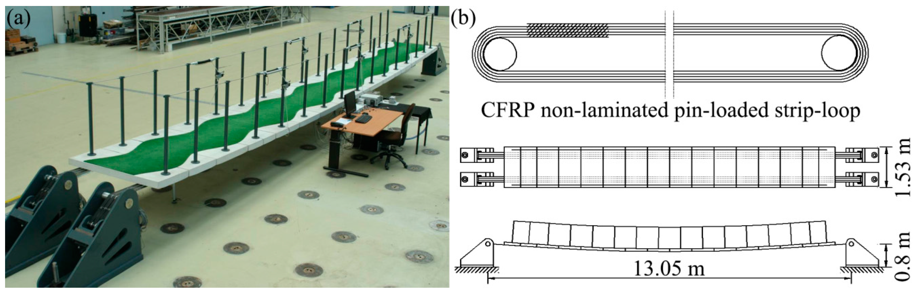
The TU Berlin CFRP Stress-Ribbon Footbridge (see
Figure 25) is a single span stress-ribbon bridge with the sag-to-span ratio of 1/60. Six 50 mm wide CFRP non-laminated pin-loaded strip-loop cables are used as load bearing components in this bridge, which were also provided by Carbo-Link GmbH, Switzerland. Each cable has 2 × 5 layers and the total thickness is approximately 1.1 mm. The load bearing capacity of a single cable is 105 kN. These cables are similar to the CFRP strip-loop cables used in the EMPA Bowstring Arch Footbridge, while the differences are that the steel pins are used in this case and the part between the strip start and strip end was bonded together through fusion. The diagrams of the cable anchorage are illustrated in
Figure 26 [
34].
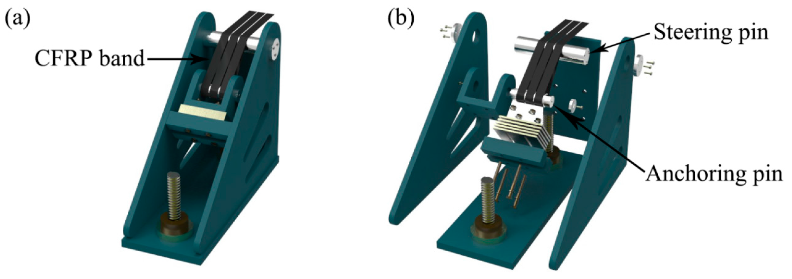
Figure 26.
Pin-loaded anchorage system, (a) assembled view and (b) exploded view.
Figure 26.
Pin-loaded anchorage system, (a) assembled view and (b) exploded view.
The above anchorage system mainly consists of two round pins, a triangular steel box and two bolts for the connection to the ground. Among the two pins, the anchor pin, with the diameter of 80 mm, is for anchoring; while the steering pin, with the diameter of 100 mm, is for changing the force direction to facilitate pre-tensioning and fixing [
34].
4.10. Cuenca Stress-Ribbon Footbridge
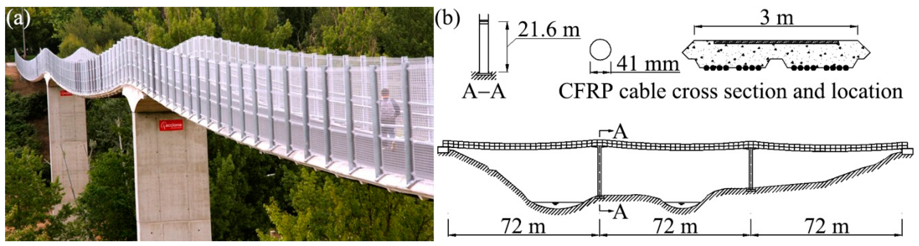
The Cuenca Stress-Ribbon Footbridge, across the Jucar River, is located in Cuenca, Spain. It is owned by Cuenca City and it was designed and constructed by ACCIONA, S.A. This bridge was completed and opened to the public in 2011. The photo and sketch of the Cuenca Stress-Ribbon Footbridge are shown in
Figure 27 [
35].
Figure 27.
Cuenca Stress-Ribbon Footbridge, (a) photo (photo credit: Juan Rodado Lopez) and (b) sketch.
Figure 27.
Cuenca Stress-Ribbon Footbridge, (a) photo (photo credit: Juan Rodado Lopez) and (b) sketch.
The Cuenca Stress-Ribbon Footbridge (see
Figure 27) is a stress ribbon bridge with three spans (72 m × 3 m). The bridge width is 3 m and the total length is 216 m, which makes it become the longest stressed ribbon bridge in Spain and the eighth in the world. This bridge has two concrete piers, whose heights are 21.6 m and 16.98 m, respectively. The bridge decks are steel reinforced concrete slabs with the dimension of 3 m × 3.5 m and the stress ribbon supporting them consists of 16 CFRP cables. These CFRP cables were divided into four groups in transverse direction and fixed under the concrete slabs. Longitudinally, the stress ribbon was divided into five sections, and each section is a CFRP cable with a length of 43.7 m and a diameter of 41 mm. These CFRP cables were connected by an “8” shaped pin connection with each other. This segmentation measure was to facilitate manufacture and transportation. Outside of the cables are aramid braided sleeves for protecting them [
35].
These CFRP cables used in the Cuenca Stress-Ribbon Footbridge were specially manufactured by Future Fibers for this project. Different from CFRP cables used in EMPA Bowstring Arch Footbridge and TU Berlin CFRP Stress-Ribbon Footbridge, these cables are CFRP laminated strip-loops cables with stainless-steel ring terminations. Indeed, the CFRP non-laminated and laminated pin-loaded strip-loop cables have both merits and demerits. In general, the former has higher ultimate bearing capacity, while the latter has greater stiffness and smaller creep. As a consequence, it is better to say that they have different uses rather than to judge which is better.
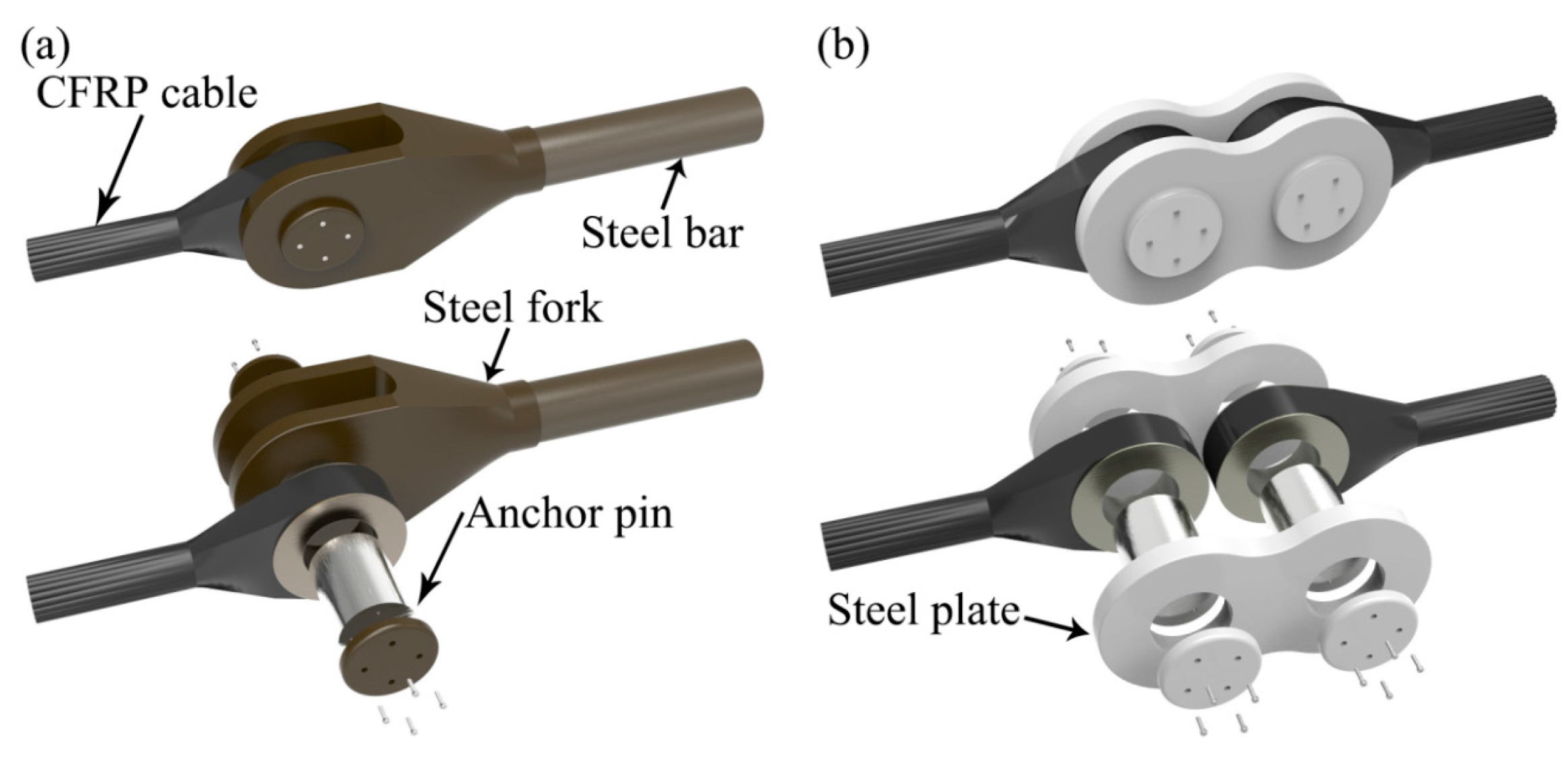
In order to anchor and connect the CFRP cables in the Cuenca Stress-Ribbon Footbridge, pin-loaded anchorages and connections were designed by engineers of ACCIONA, which are illustrated in
Figure 28 [
35].
Figure 28.
(a) Anchorage and (b) Connection for CFRP cables.
Figure 28.
(a) Anchorage and (b) Connection for CFRP cables.
Figure 28a presents the anchorage structure of CFRP cables, which consists of steel fork, steel bar and anchor pin.
Figure 28b shows the connection structure between two CFRP cables, which is formed by “8” shaped steel plates and anchor pins. The steel bar of the anchorage is pre-tensioned and anchored at the abutment back wall by spherical nut and anchor plate [
35].
5. Future Development of CFRP Cable Structures
As can be seen from the above section, all the existing CFRP cable structures are cable bridges. Moreover, majority of them are cable-stayed bridges. Up to now, there is not yet any CFRP cable roof or cable facade in the world.
However, cable roofs and cable facades are ideal structures for CFRP cables, because most of them are orthogonally loaded by external loads. In orthogonally loaded cable structures, such as many cable roofs and cable facades, the structural stiffness is mainly comprised of the geometric stiffness, which is controlled by the pre-tension force of cables, instead of the elastic stiffness controlled by the elastic modulus of cables. This means, for such cable structures, increasing the tensile strength of cables to increase the pre-tension force is a more efficient way to either raise the structural stiffness if the amount of cable used remains unchanged or reduce the amount of cable used if the structural stiffness is maintained, compared to increasing the elastic modulus of cables. This phenomenon also indicates that using CFRP cables, whose tensile strength is considerably greater than that of steel cables (see
Table 3), in the orthogonally loaded cable structures will improve the economic efficiency of structures, although the elastic modulus of CFRP cables is usually smaller than that of steel cables (see
Table 3) and their unit price is also much higher [
36,
37].
Therefore, using CFRP cables in cable roofs and cable facades is an important development direction in the future.
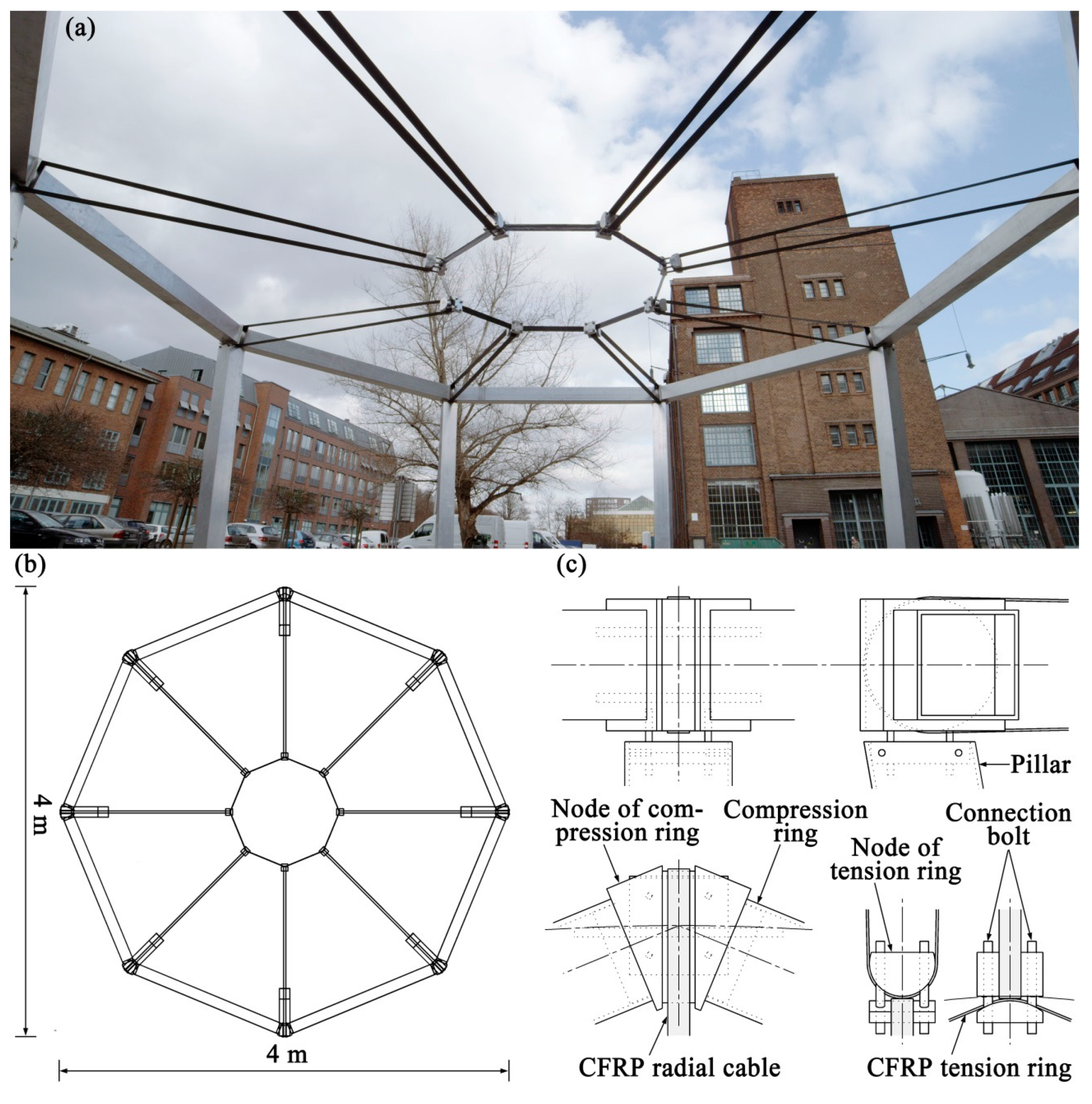
5.1. Prototype of CFRP Spoked Wheel Cable Roof
To investigate the feasibility of applying CFRP cables to cable roofs and cable facades, a small CFRP spoked wheel cable roof was built at TU Berlin in 2013 [
36].
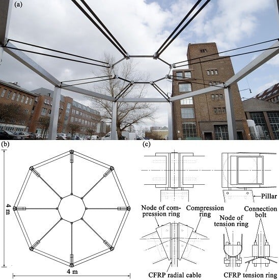
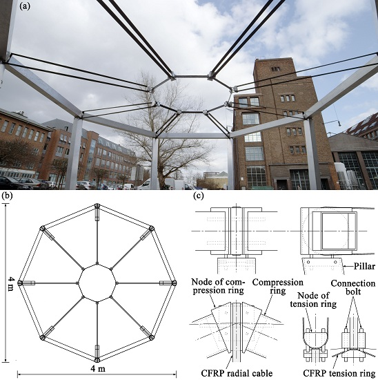
This prototype structure had a diameter of 4 m and contained all three primary structural elements of a real spoked wheel roof: the compression ring, the tension ring and the radial cables. All tension-loaded structural members, such as the tension ring and the eight radial cables, were made of CFRP. The material of the compression ring, pillars and nodes was aluminum [
36].
The radial cable was a loop-shaped CFRP tension member, and the tension ring was a closed octagon CFRP loop. They were all composed of parallel carbon fibers embedded in a polymer matrix. The C 30 fiber type from the SGL Group was used with an epoxy resin matrix. The cross section of the radial cable and the tension ring was 30 mm × 1.2 mm, which contains approximately 20 million carbon fibers and could bear nearly 80 kN tension force. Both types of CFRP structural elements were manufactured at TU Berlin by laminating a continuous carbon fiber tow coated with epoxy resin on a rotating form and using vacuum technique to harden [
36].
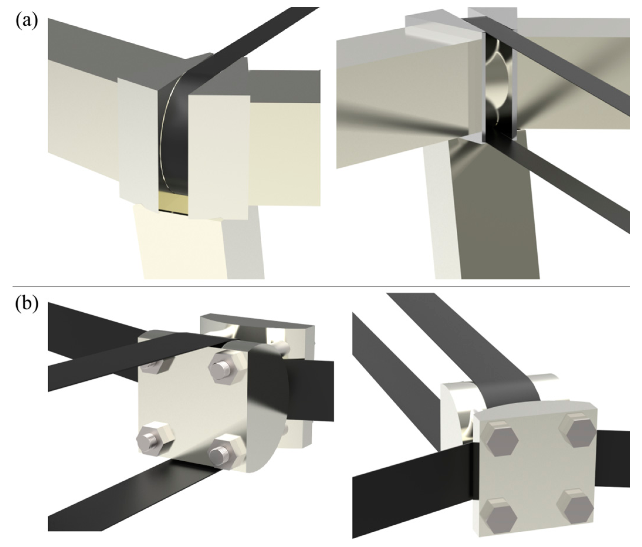
The connection between the radial cables and both rings was made with aluminum nodes. Because all CFRP cables were loop-shaped, the aluminum nodes also had cylindrical surfaces (see
Figure 29c and
Figure 30) [
36].
To pre-tension the CFRP cables, each node of the tension ring was separated into two parts, which were linked together by four bolts. By tightening the bolts and hence shortening the distance between these two parts, the CFRP cable system of the spoked wheel cable roof was pre-tensioned to a sufficient level [
36].
This prototype demonstrated that CFRP cable roofs are already feasible today. According to the experiences of building this prototype, new cable shapes and anchoring strategies different from those for steel cables should be developed for CFRP cables according to their unique characteristics.
5.2. CFRP Continuous Band Winding System
The CFRP Continuous Band Winding System is a novel design of using CFRP in cable roofs and cable facades. As its name suggest, the cables used in such system are CFRP continuous bands, which will be wound through all the intermediate nodes and only anchored at both end nodes or which will form closed loops without any anchorages. The greatest advantage of the CFRP continuous band winding system is that the number of anchorages is minimized and thus exploiting to the full favorable conditions of CFRP cables and avoid the unfavorable ones [
38].
Figure 29.
(a) Photo of CFRP spoked wheel cable roof at TU Berlin (photo credit: Till Beckmann); (b) plan view; and (c) nodes of compression ring and tension ring.
Figure 29.
(a) Photo of CFRP spoked wheel cable roof at TU Berlin (photo credit: Till Beckmann); (b) plan view; and (c) nodes of compression ring and tension ring.
Figure 30.
(a) Node at outer compression ring and (b) node at inner tension ring.
Figure 30.
(a) Node at outer compression ring and (b) node at inner tension ring.
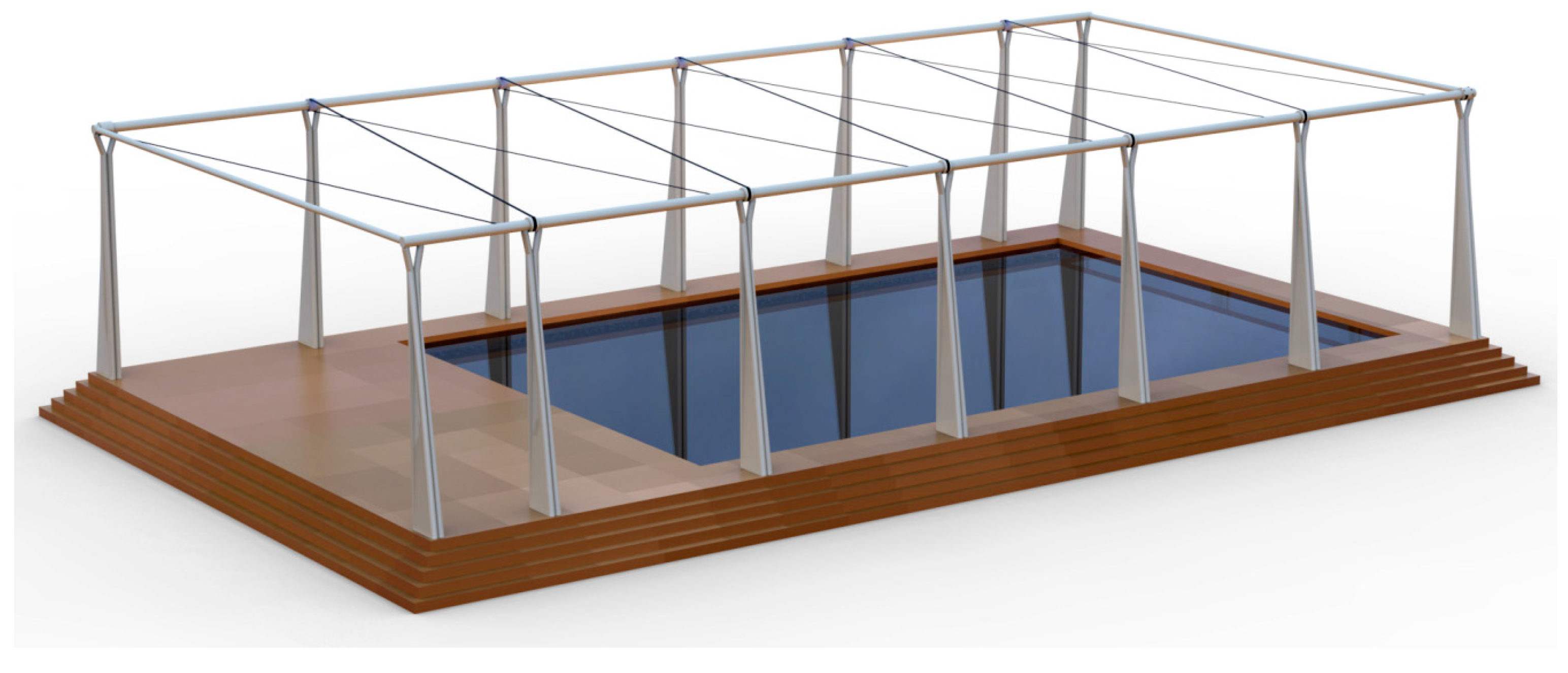
There are several forms of CFRP Continuous Band Winding Systems. One of them is illustrated in
Figure 31, which is a cable system of cable membrane roof for a swimming pool. The details of the CFRP continuous band used and the nodes are illustrated in
Figure 32 [
38].
Figure 31.
Swimming pool cable roof with CFRP Continuous Band Winding System.
Figure 31.
Swimming pool cable roof with CFRP Continuous Band Winding System.
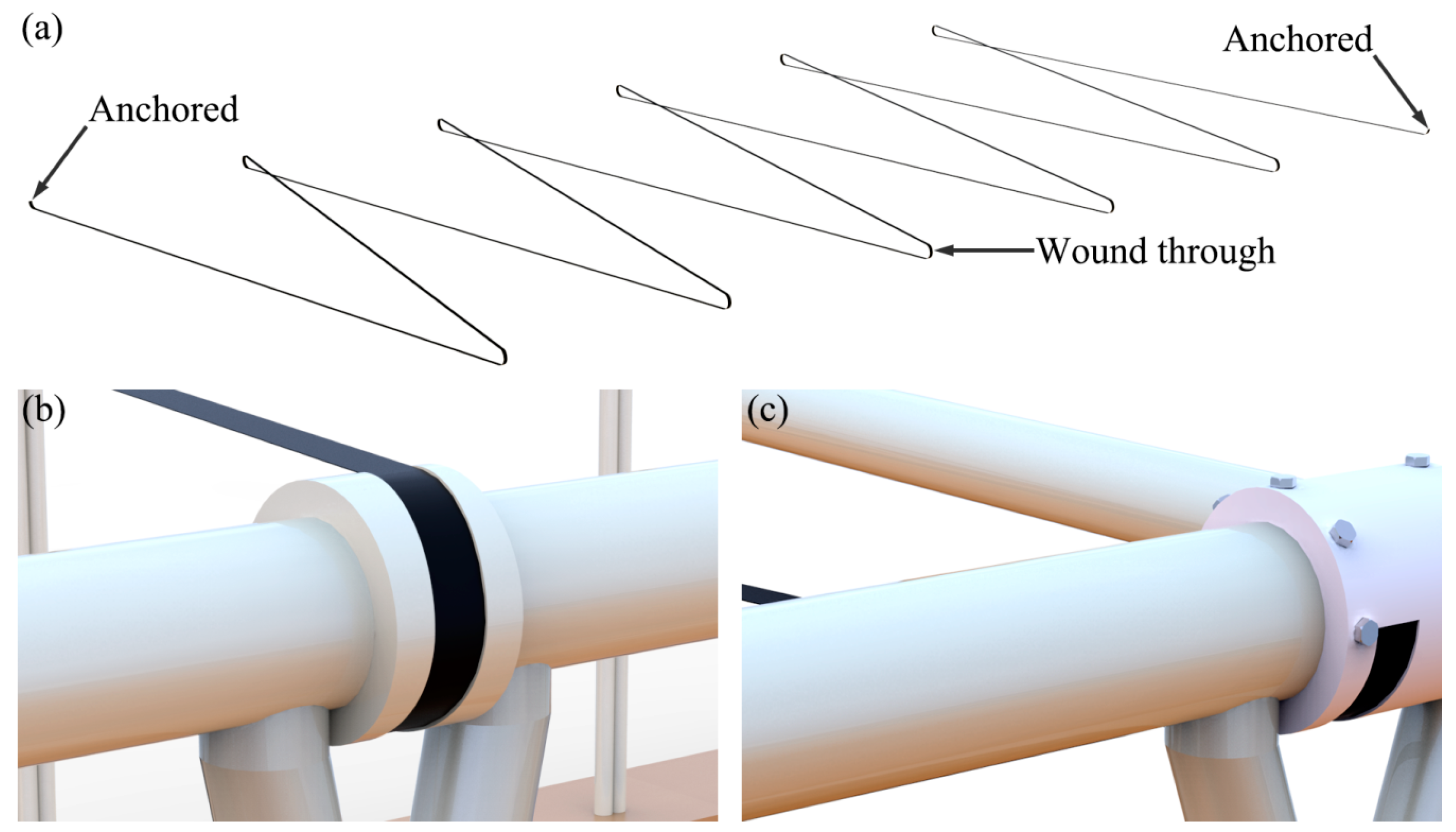
Figure 32.
(a) CFRP continuous band used; (b) intermediate node; and (c) end node.
Figure 32.
(a) CFRP continuous band used; (b) intermediate node; and (c) end node.
As can be seen from the above figures, there is only one cable,
i.e., a CFRP continuous band, used in the structure, which makes the cable structure very concise and aesthetically pleasing. Furthermore, the CFRP continuous band is only anchored at both end nodes (see
Figure 32c), while it is wound through every intermediate node (see
Figure 32b).
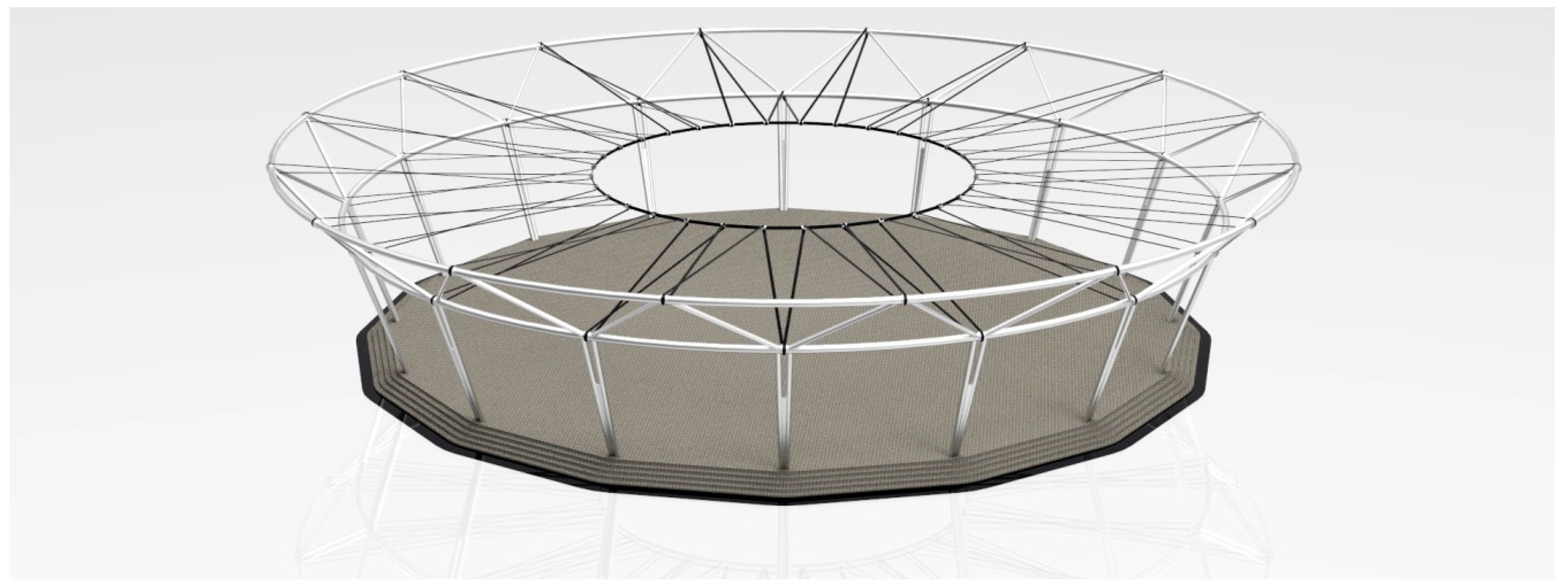
Another form of the CFRP Continuous Band Winding System is illustrated in
Figure 33, which is a CFRP spoked wheel cable roof. The details of the CFRP continuous band used and the nodes are illustrated in
Figure 34 [
38].
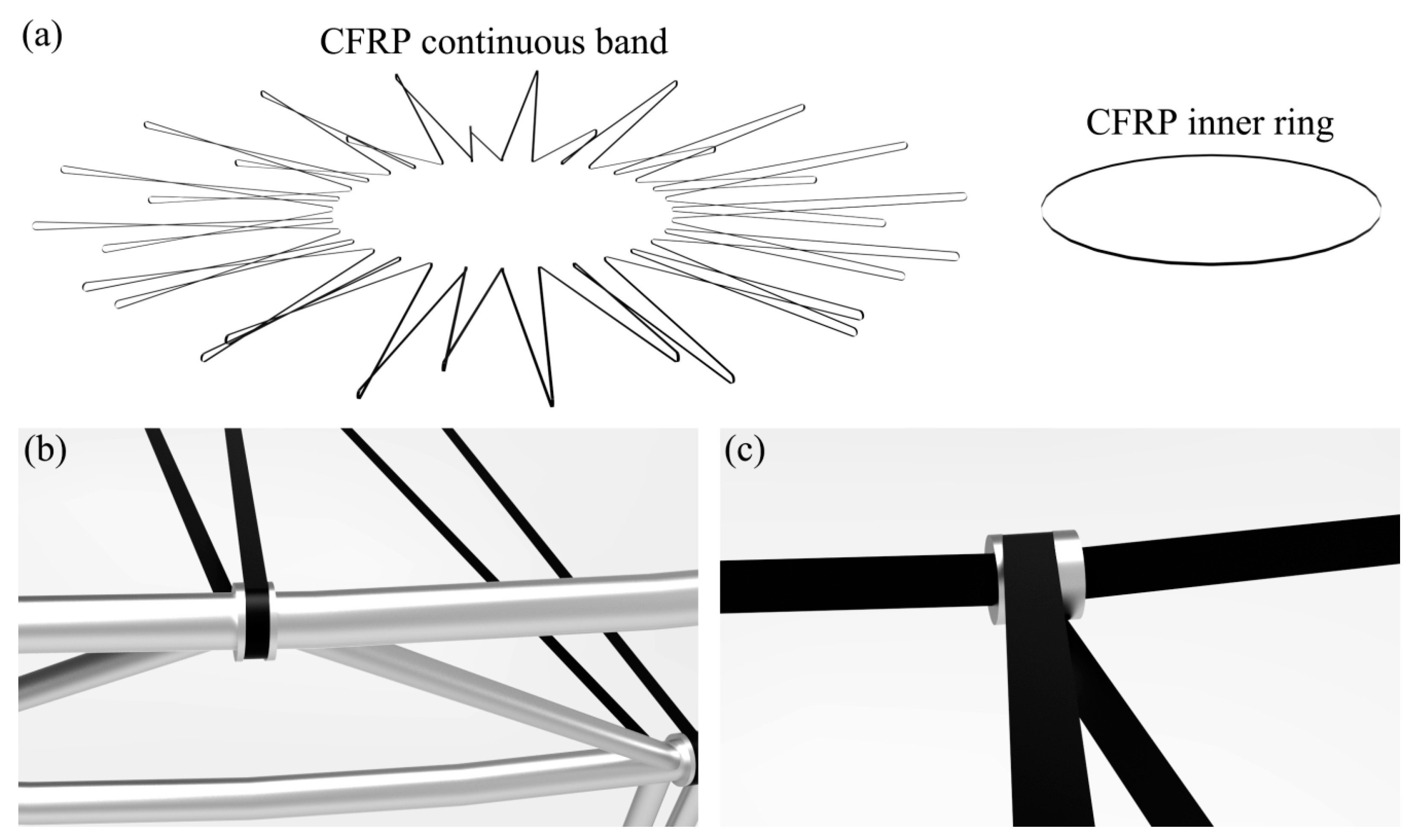
As can be seen from the above figures, there are only two cables in the structure, i.e., a CFRP continuous band acting as the spoke cables and a CFRP inner ring. The CFRP continuous band forms a closed loop and is wound around all nodes without any anchorages.
Admittedly, aside from the advantages, the CFRP continuous band winding system also has some disadvantages. For example, the failure of a single segment of the CFRP continuous band may result in the failure of the whole system; therefore, the safety factor for the CFRP continuous band might be set higher than that for ordinary cables. In general, the CFRP Continuous Band Winding System is an interesting and promising way of using CFRP in cable roofs and cable facades. More researches are needed for its realization.
Figure 33.
Spoked wheel cable roof with CFRP Continuous Band Winding System.
Figure 33.
Spoked wheel cable roof with CFRP Continuous Band Winding System.
Figure 34.
(a) CFRP continuous band used; (b) node at compression ring; and (c) node at tension ring.
Figure 34.
(a) CFRP continuous band used; (b) node at compression ring; and (c) node at tension ring.
6. Existing Challenges for CFRP Cable Structures
Although the future of CFRP cable structures is brilliant, there are still some challenges or problems, which may obstruct their wide applications. The difficulty of anchoring CFRP cables is one of the challenges, which has been introduced with possible solutions in previous chapters.
Besides being hard to be anchored, poor fire resistance of CFRP cables is another challenge. Most CFRP materials degrade when exposed to moderately elevated temperature conditions [
39]. Usually, the polymer resin, which is the organic matrix of CFRP, becomes rubbery and viscous, if the temperature ranges from 65 °C to 130 °C [
39]. At temperatures above 300 °C, the polymer resin may combust and evaporate, releasing heat, smoke, soot and toxic volatiles [
40,
41]. It further causes decomposition of carbon fibers [
39]. Meanwhile, the CFRP will lose the strength and stiffness, which will result in the failure of CFRP cable structures [
42]. Consequently, appropriate fire protection measures should be considered in the design of CFRP cable structures.
Up to now, there are two main measures that can prevent or minimize the possible fire damage to CFRP cable structures. The first method is to spray a fire resistant coating on the surface of CFRP cables [
39]. This intumescent coating can ensure that the temperature of CFRP cables do not reach their critical temperature for the required duration during fire. The critical temperature can be defined as the temperature at which the cables lose so much of their strength or stiffness that they can no longer support the applied loads [
43]. There are now several appropriate fire resistant coatings on the market, for example, the FF 88 from Firefree Coatings, Inc. It is a water-based intumescent coating, which can withstand extreme temperatures (up to 1093 °C for an extended period of time of up to 1 h) [
39,
44]. Another method is to increase the fire resistance of the CFRP itself, which is the fundamental method to solve the fire protection problem. For example, the organic resin-based matrix of CFRP can be replaced with a fire resistant cement-based matrix [
45]. For another instance, nanoclay particles can be added into the polymer resin of CFRP to significantly increase the fire resistance [
39].
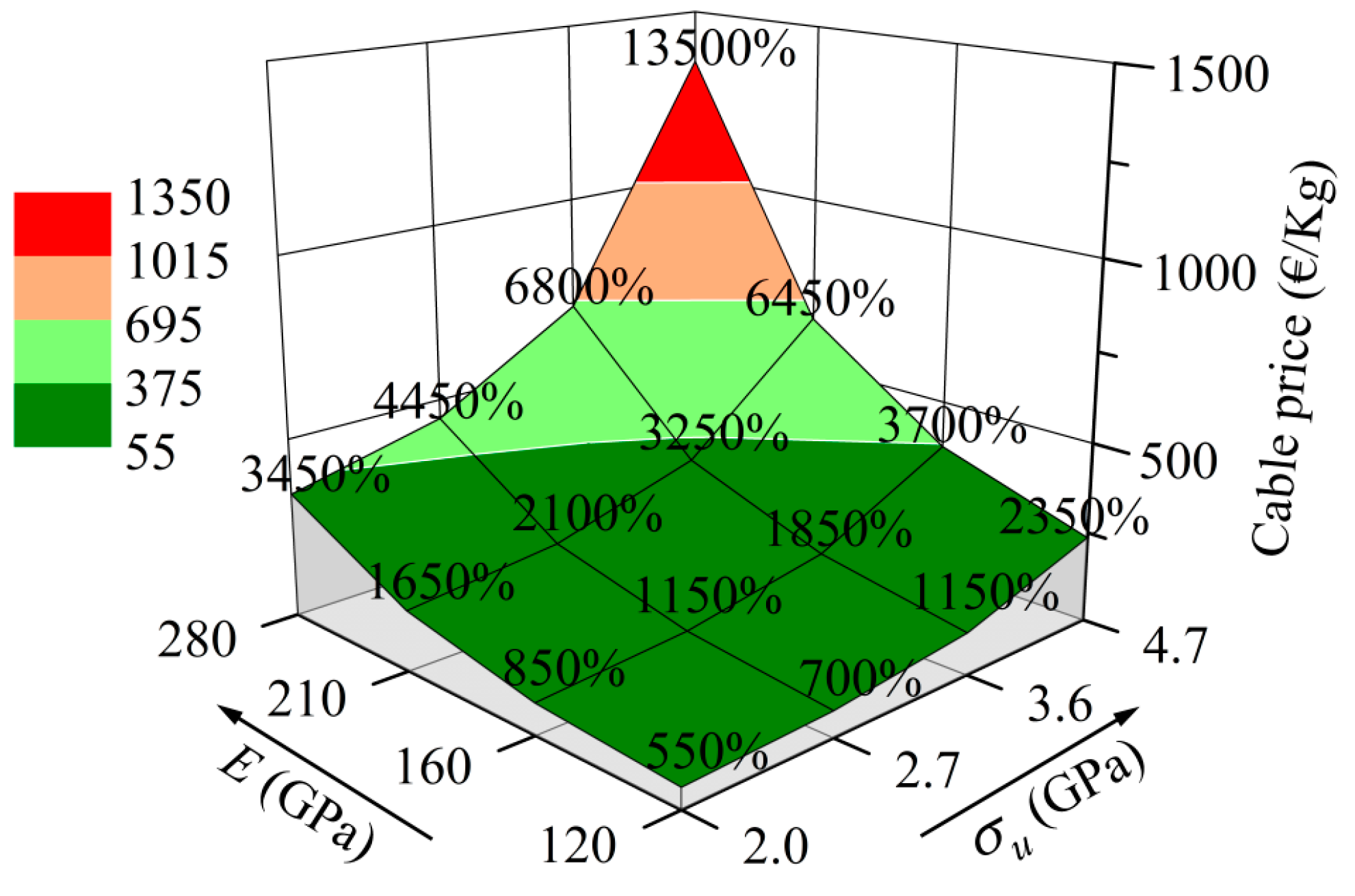
In addition to the obstacles in respects of mechanics and physics, high unit price is also a challenge that obstructs the widespread use of CFRP cables in cable structures. Usually, the unit price of CFRP cables is influenced by the tensile strength and the elastic modulus. Through personal inquiries of the producers and also considering the information from the Internet, Literature [
38] estimated the unit prices (prices per unit weight) of CFRP cables with different tensile strengths σ
u and different elastic moduli
E, which is shown in
Figure 35, compared with the steel full-locked coil rope cable whose unit price is approximately 10 €/kg. In this figure, the percentages represent the ratios of unit prices of CFRP cables to that of steel cable and the directions of arrows indicate the increasing directions of σ
u and
E.
Figure 35.
Estimate of unit prices of CFRP cables compared to that of steel cable.
Figure 35.
Estimate of unit prices of CFRP cables compared to that of steel cable.
As seen from
Figure 35, the unit prices of CFRP cables are much higher than that of steel cable; moreover, the unit price rises with the increase of either σ
u or
E of CFRP cables and the increase of
E makes the price increase slightly faster than that of σ
u.
The exorbitant unit price of CFRP cables might prevent the CFRP cable structures achieving economic efficiency compared to the corresponding steel cable structures. However, the literature [
36,
37,
38] demonstrated that using CFRP cables in some cable structures (e.g., cable net facade) can achieve the economic efficiency through considerably reducing the amount of cable used. Furthermore, CFRP cable structures can be economically competitive in some cases, if the life-cycle cost is taken into consideration [
46,
47].
7. Conclusions
The history of building is a history of building materials. The emergence of a new material can usually promote the development of the structures. Carbon Fiber Reinforced Polymer (CFRP) is a new high performance composite material with many advantages, such as long breaking length, no corrosion and excellent fatigue resistance. In the early 1980s, the introduction of CFRP instead of steel for cables had already been proposed. After decades of development, CFRP cables are now driving the progress of cable structures.
This paper mainly reviews the ten existing CFRP cable structures in the world. All of them are CFRP cable bridges. Although these CFRP cable structures were principally built for test purposes, their successful constructions and good long-term services have fully confirmed that replacing steel cables with CFRP cables in cable structures is feasible based on the present technology. Because of the strong orthotropy of CFRP, steel cable anchorages cannot directly be used to anchor CFRP cables. In the existing CFRP cable structures, the corresponding anchorages were specially designed according to the characteristics of CFRP. In addition, using CFRP cables in cable roofs and cable facades is overviewed in this paper, which is a great potential application area for CFRP cables in the future. A prototype CFRP spoked wheel cable roof is introduced and a novel design without any anchorages, i.e., the CFRP Continuous Band Winding System, is also presented.
Admittedly, there are still several challenges and obstacles hindering the wide applications of CFRP cables, such as difficulty in anchoring, the fire safety problem and the relatively high price. However, this should not prevent us from going ahead with the advancement in the domain of CFRP cables. The structural engineering community of today needs to encourage the engineering practice of CFRP cables structures, so as to promote the further development of cable structures.


