
Fatigue and Wear Performance of Autoclave-Processed and Vacuum-Infused Carbon Fibre Reinforced Polymer Gears
Abstract
:1. Introduction
2. Materials and Methods
2.1. Gears’ Production
2.2. Thermomechanical and Frictional Characteristics of the ET445 CIT Composite
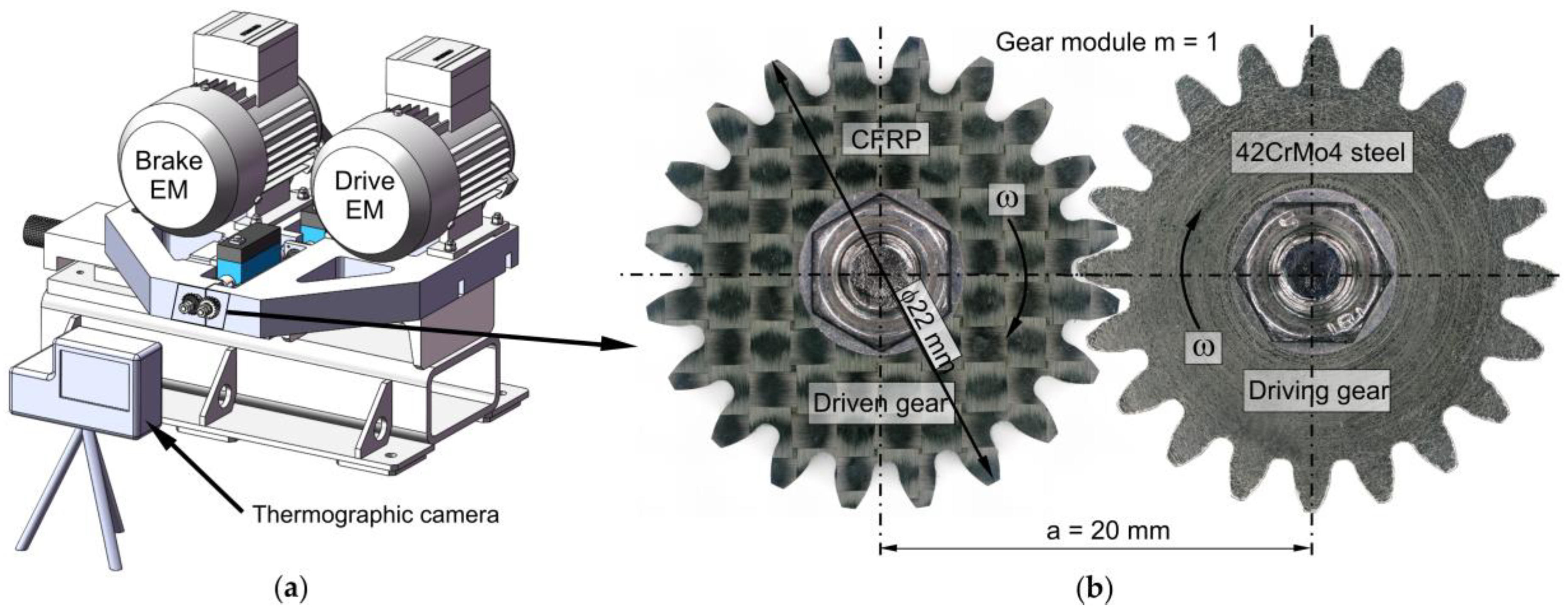
2.3. Gear Testing Methodology
2.4. Scanning Electron Microscopy (SEM)
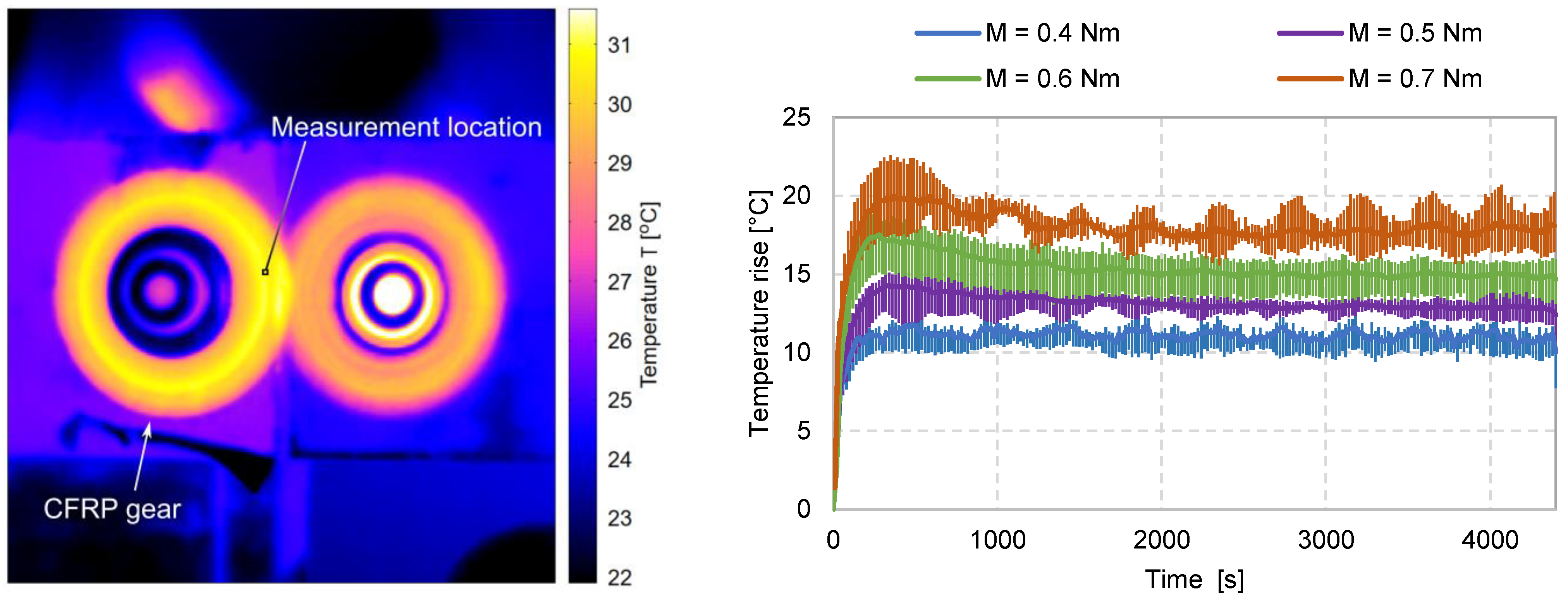
2.5. Temperature Measurements
2.6. Wear Measurement
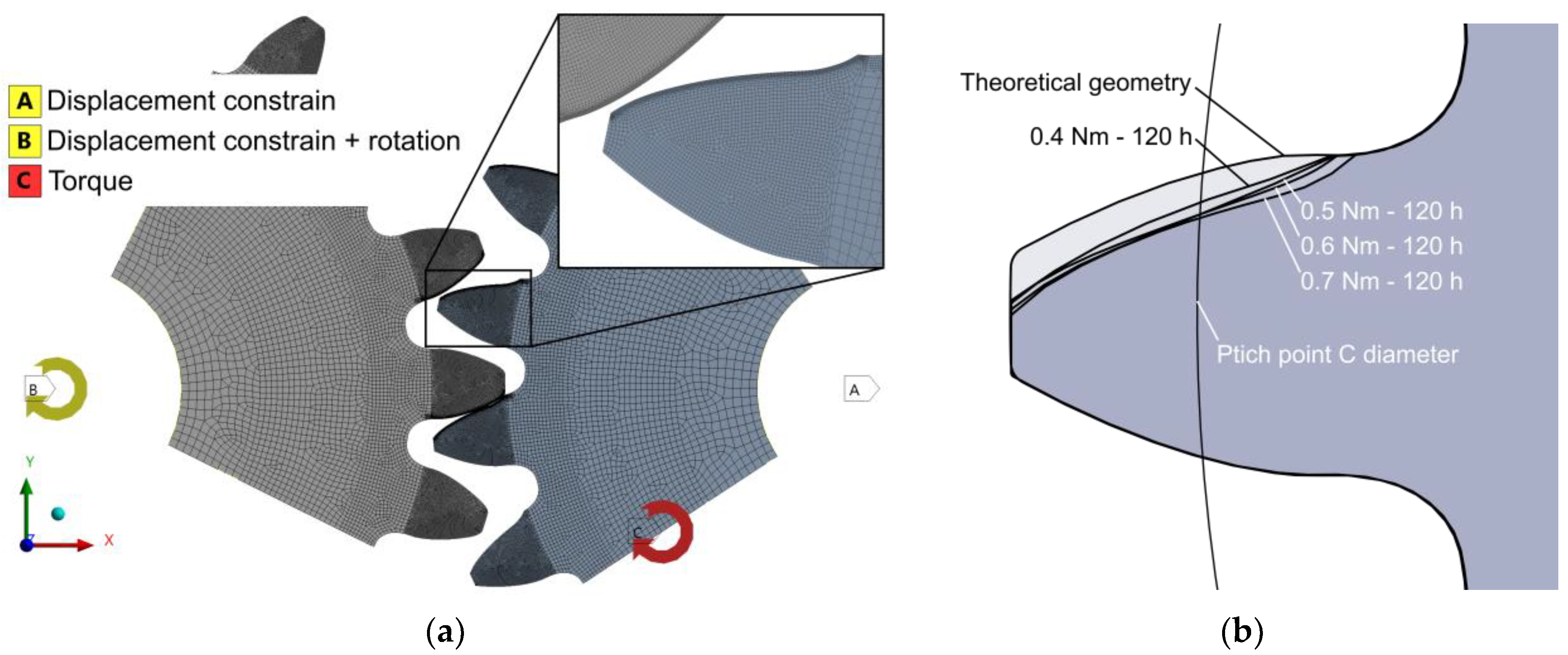
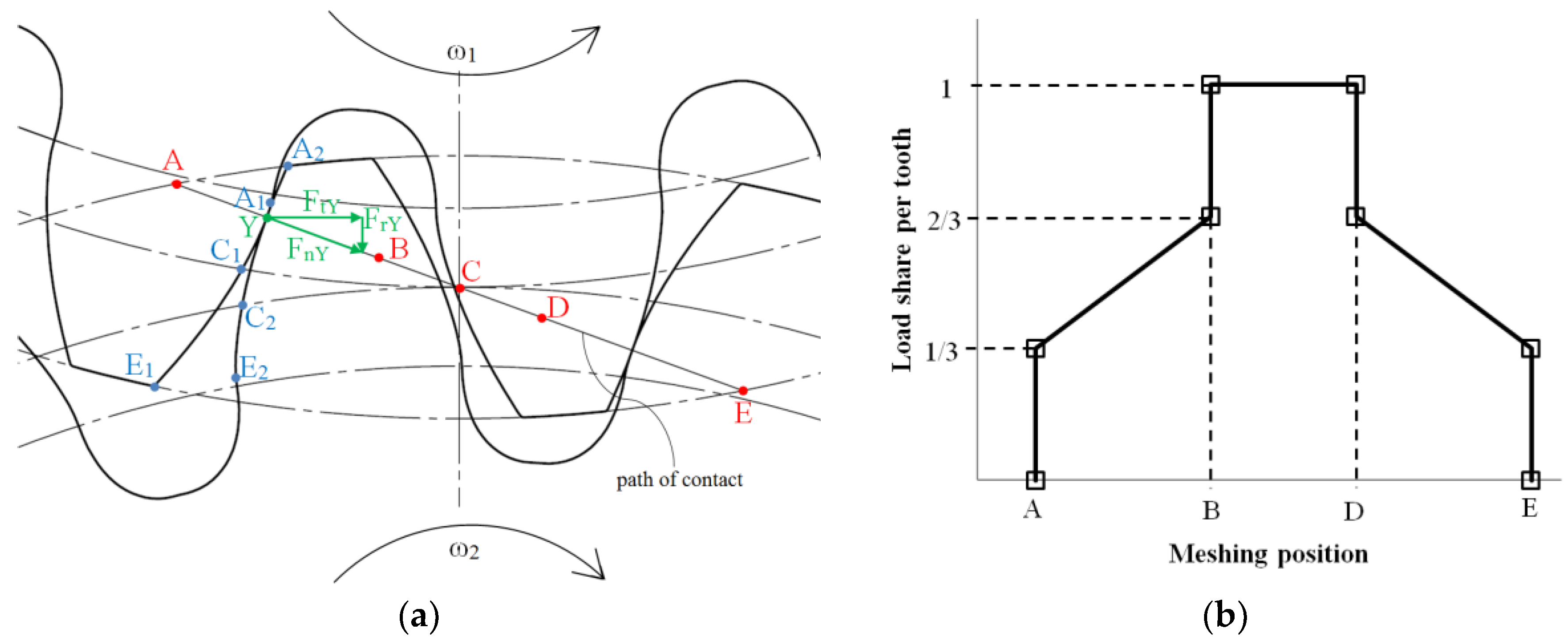
2.7. Numerical Analyses
3. Results
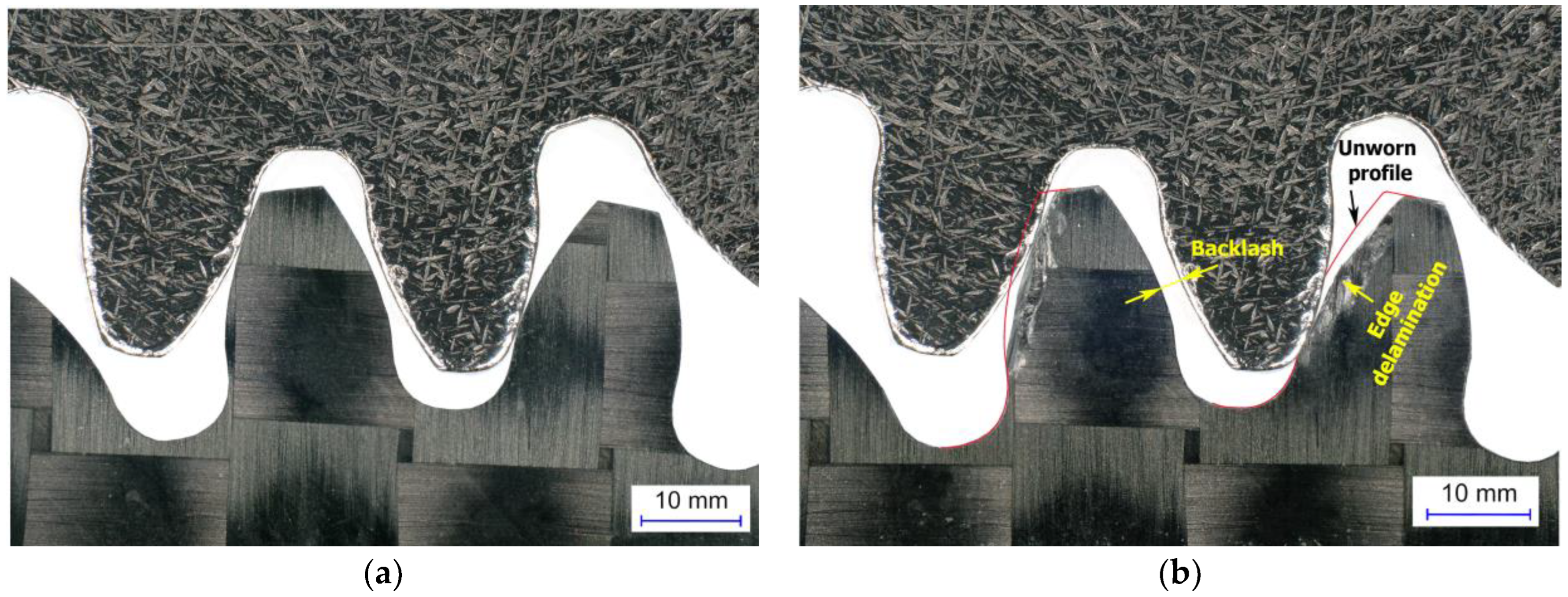
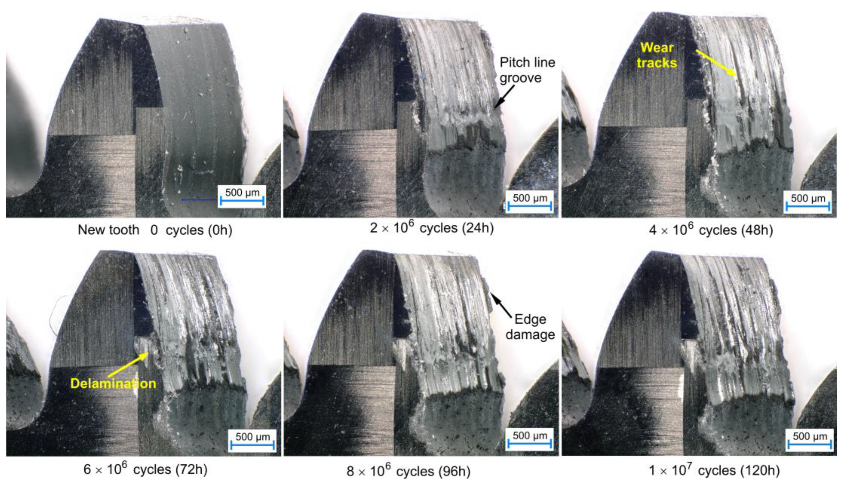
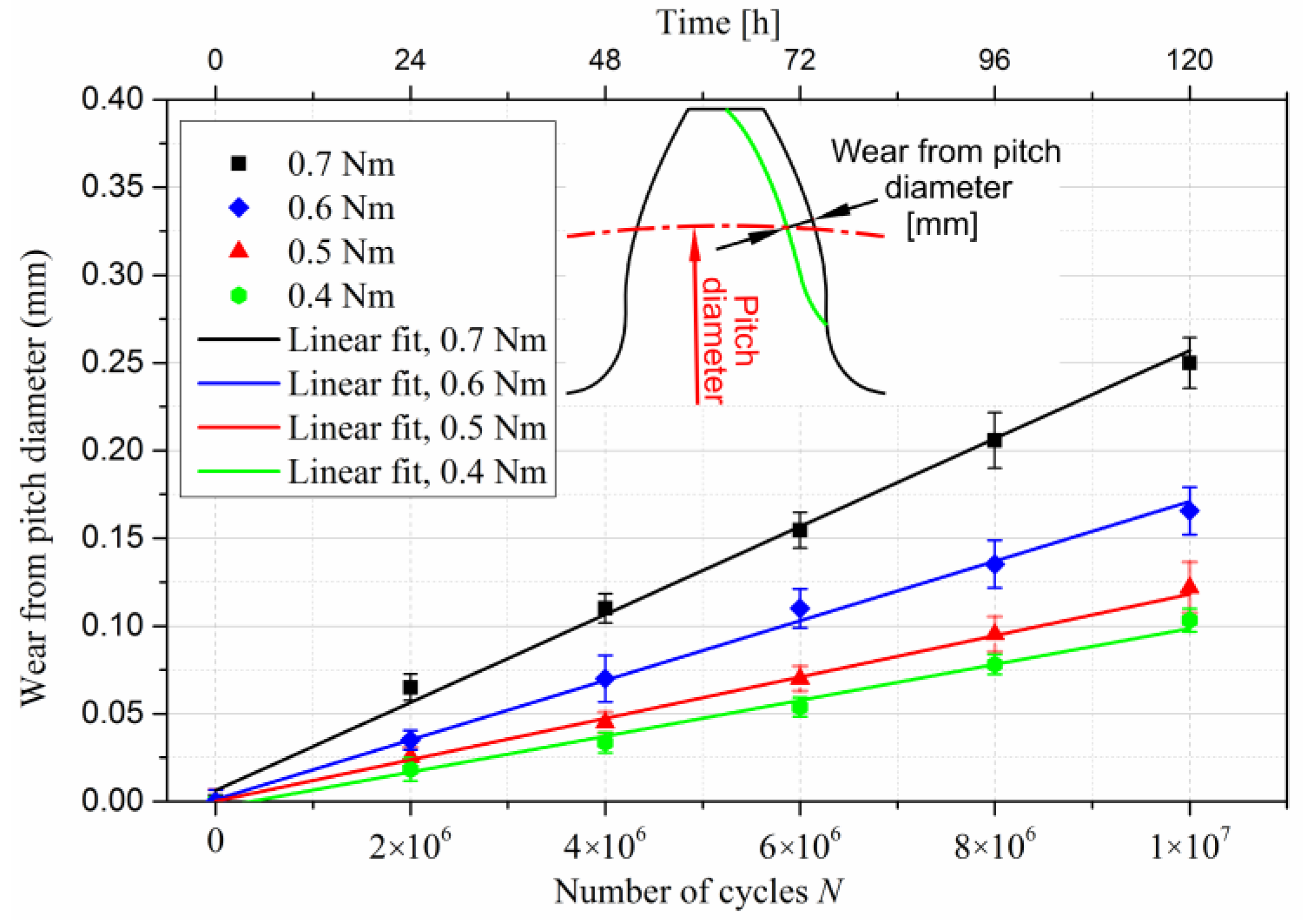
3.1. Wear Characteristics of CFRP Gears
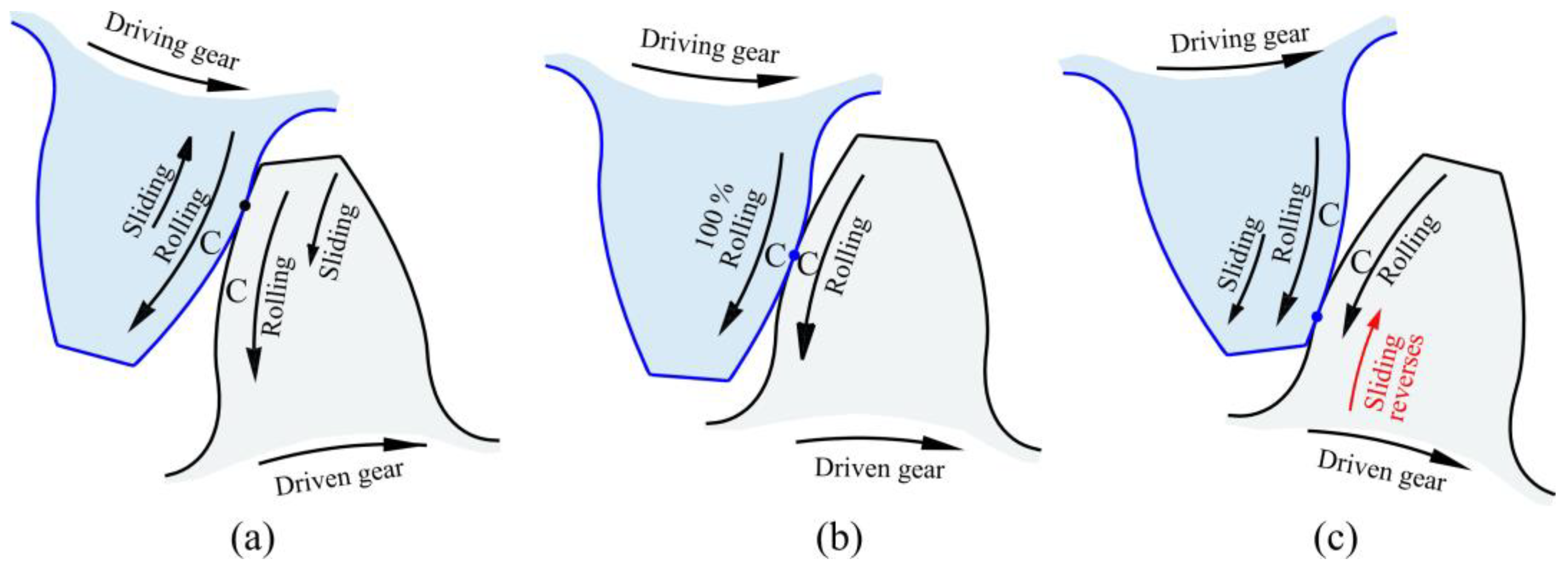
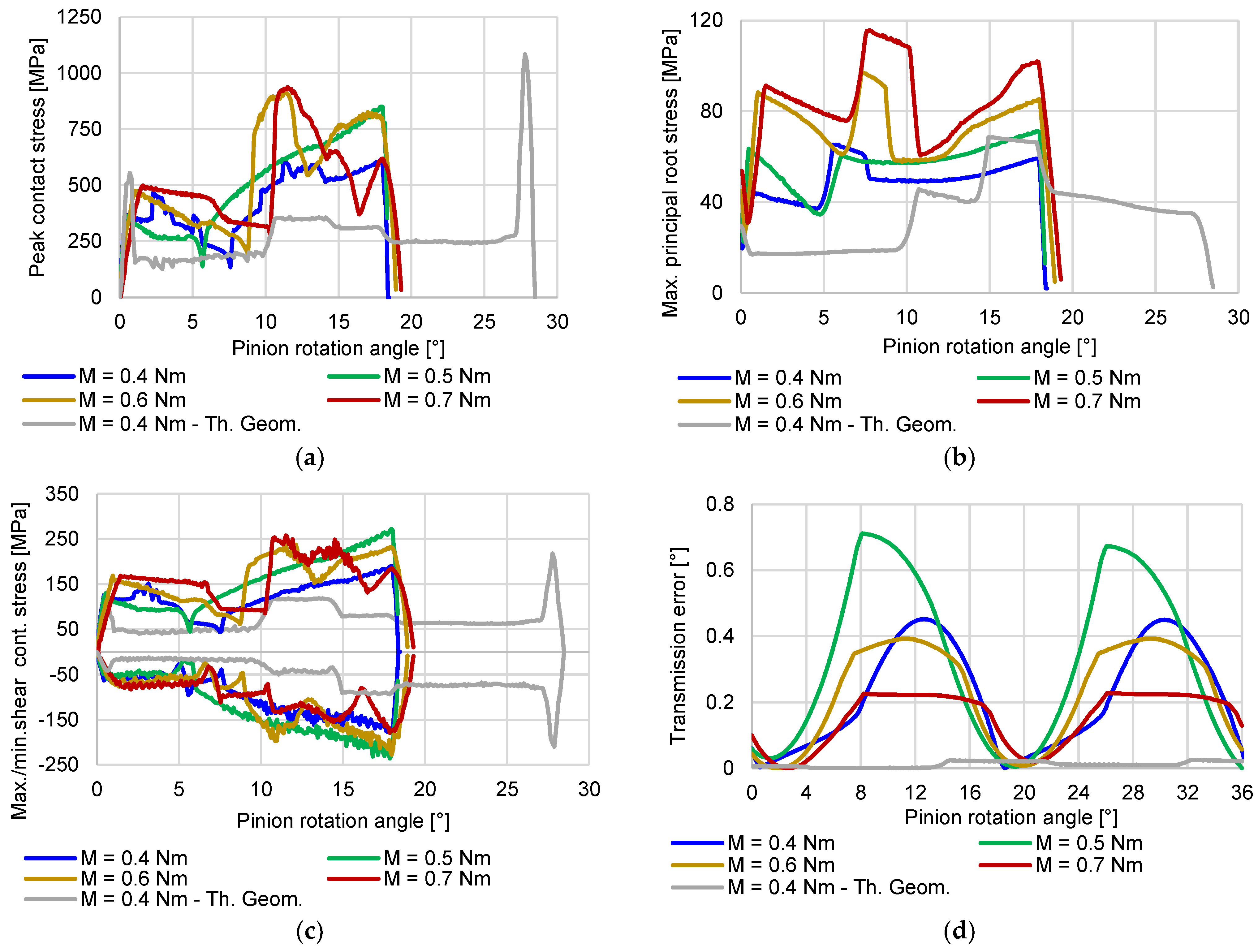
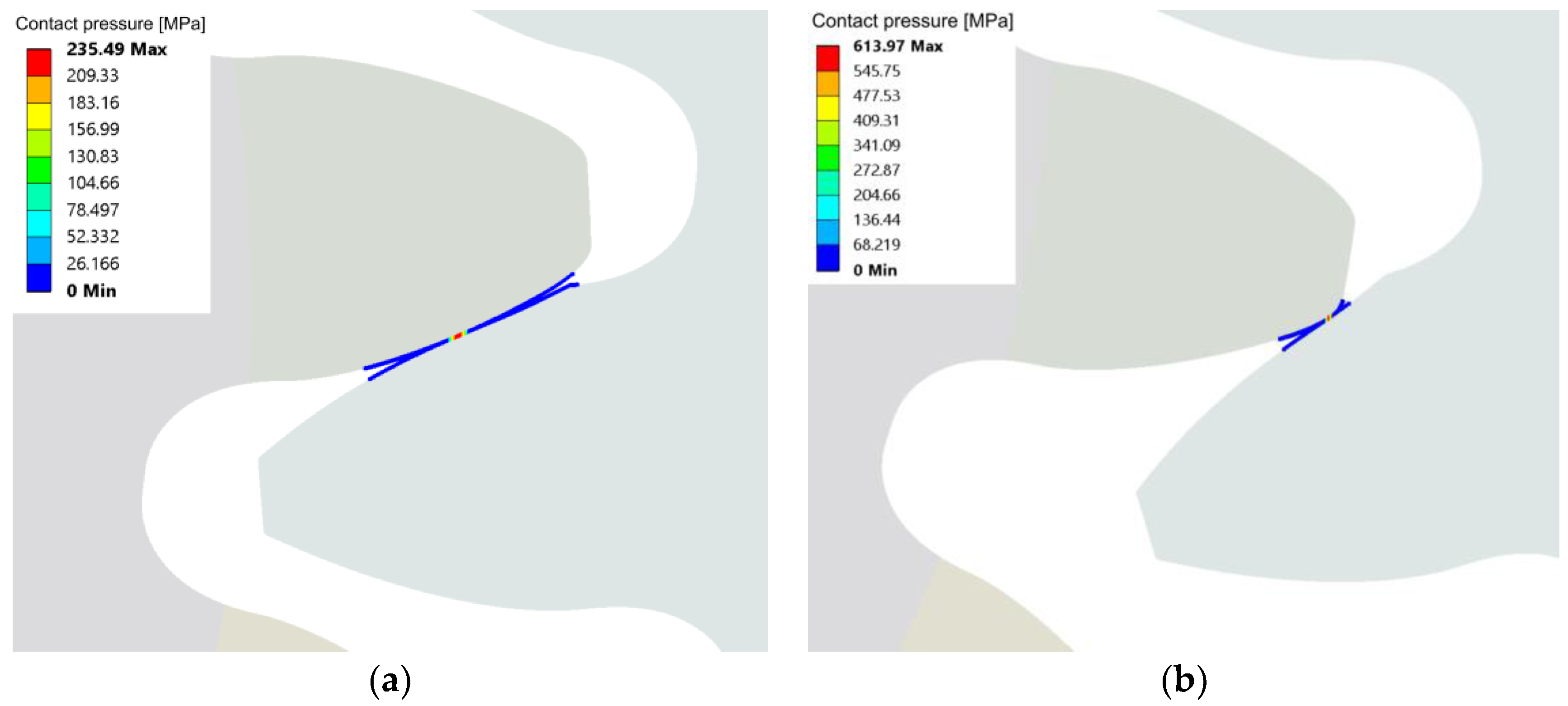
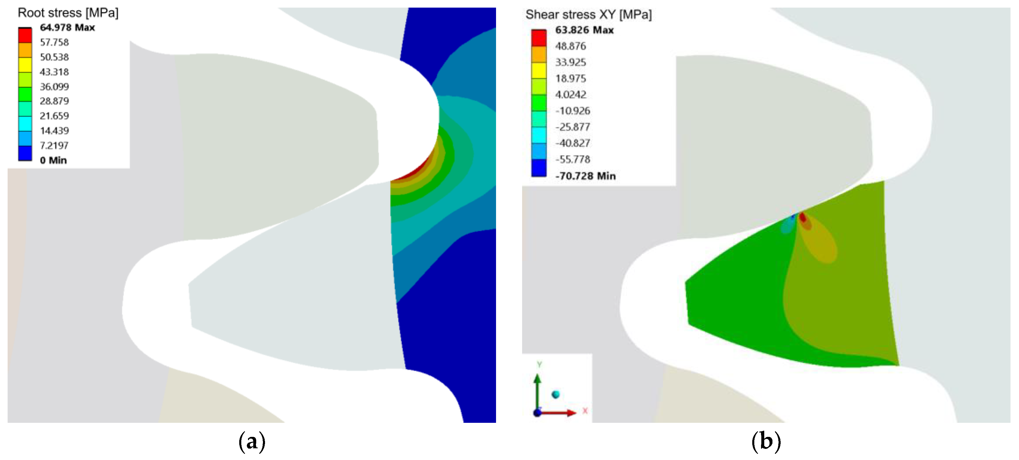
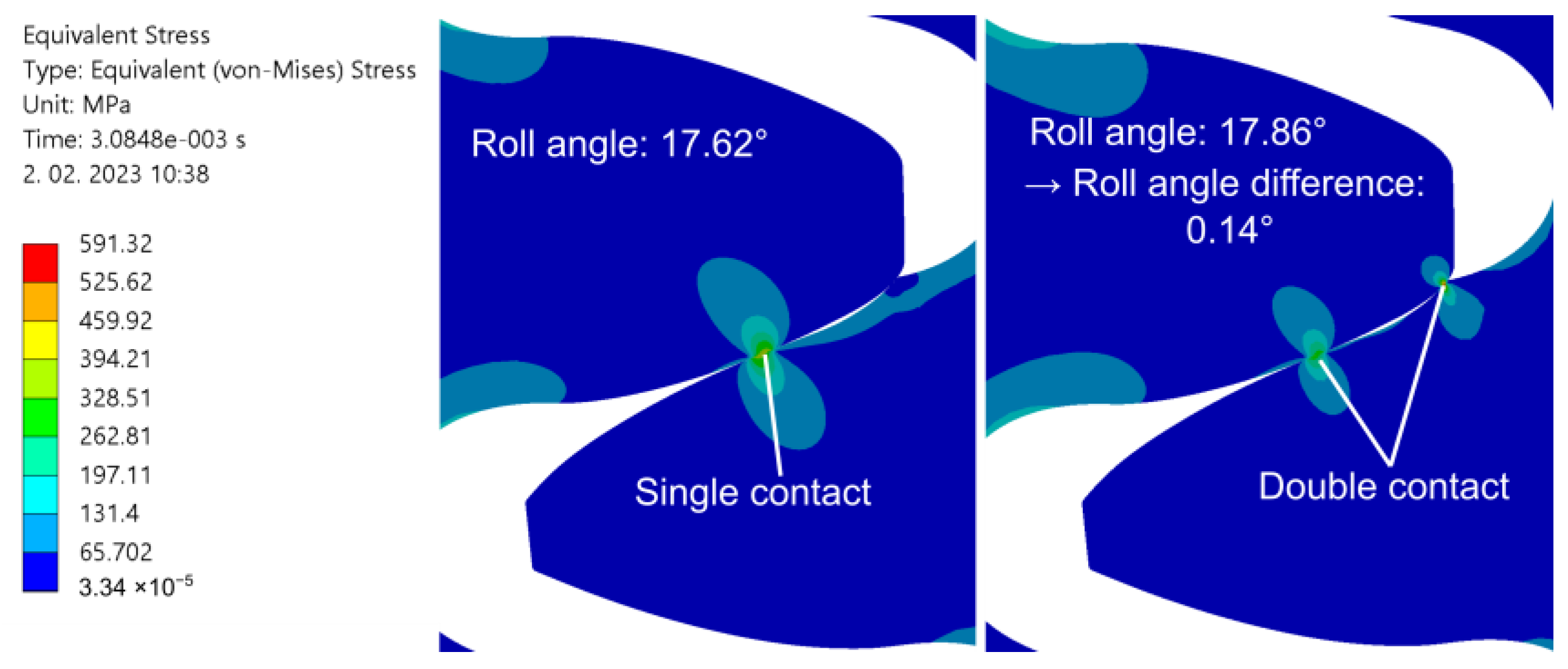
3.2. Numerical Analysis
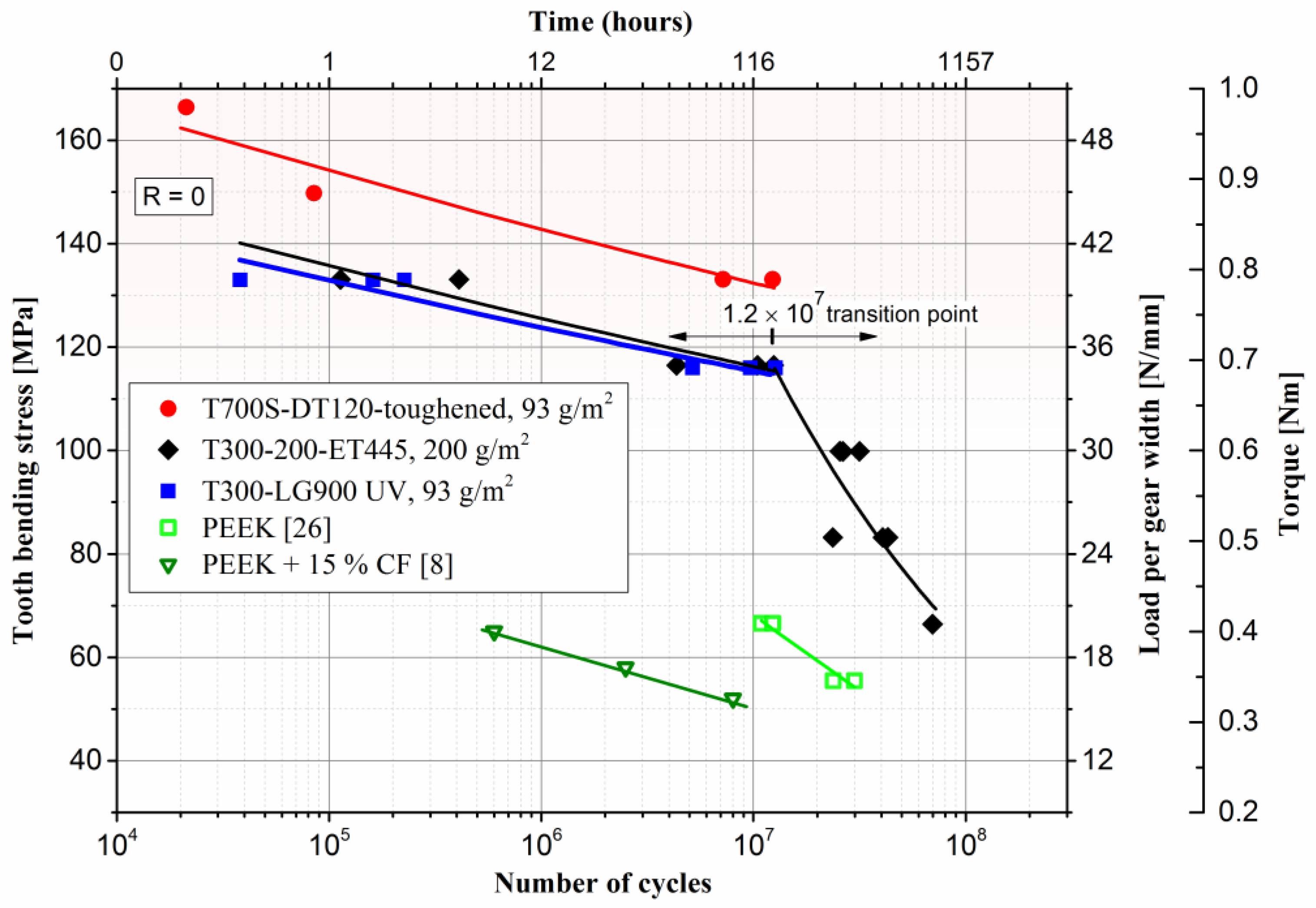
3.3. Fatigue Properties of CFRP
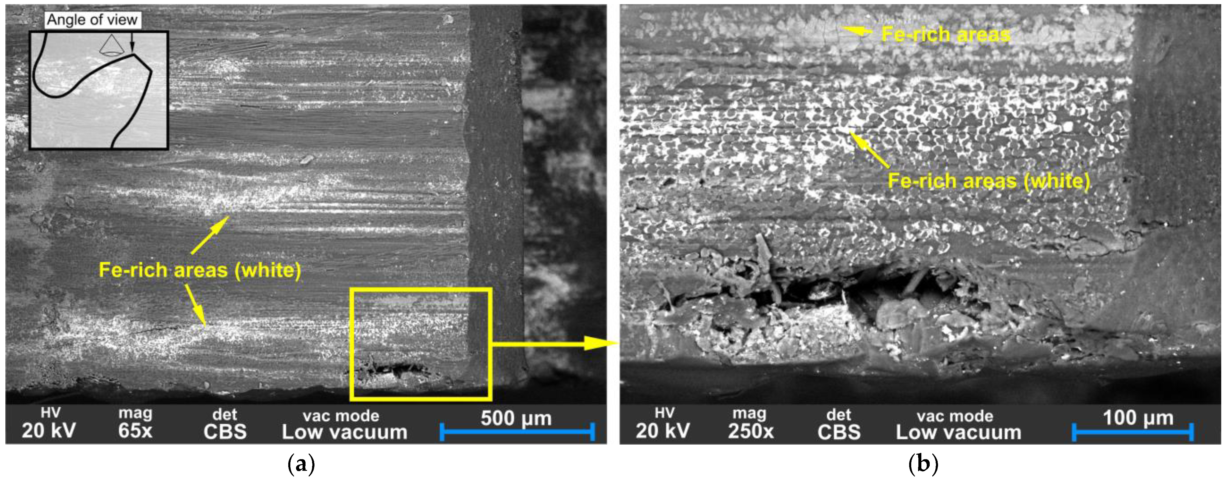
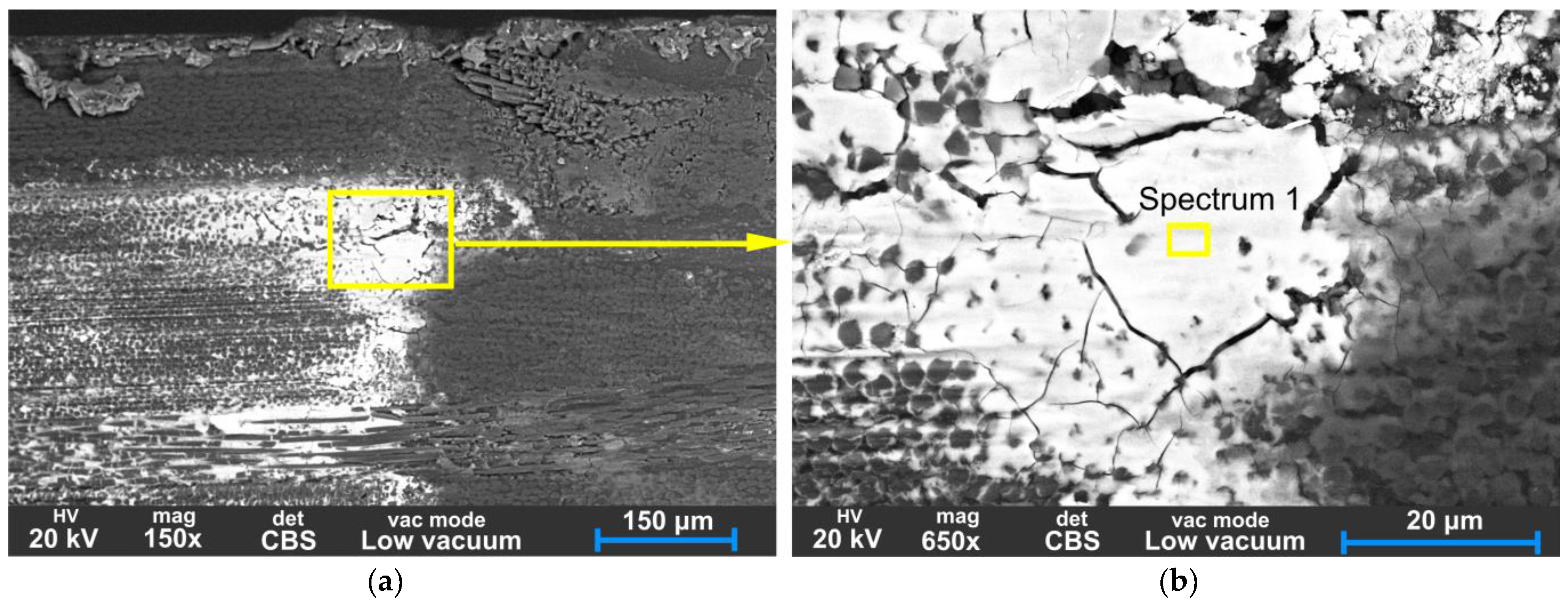
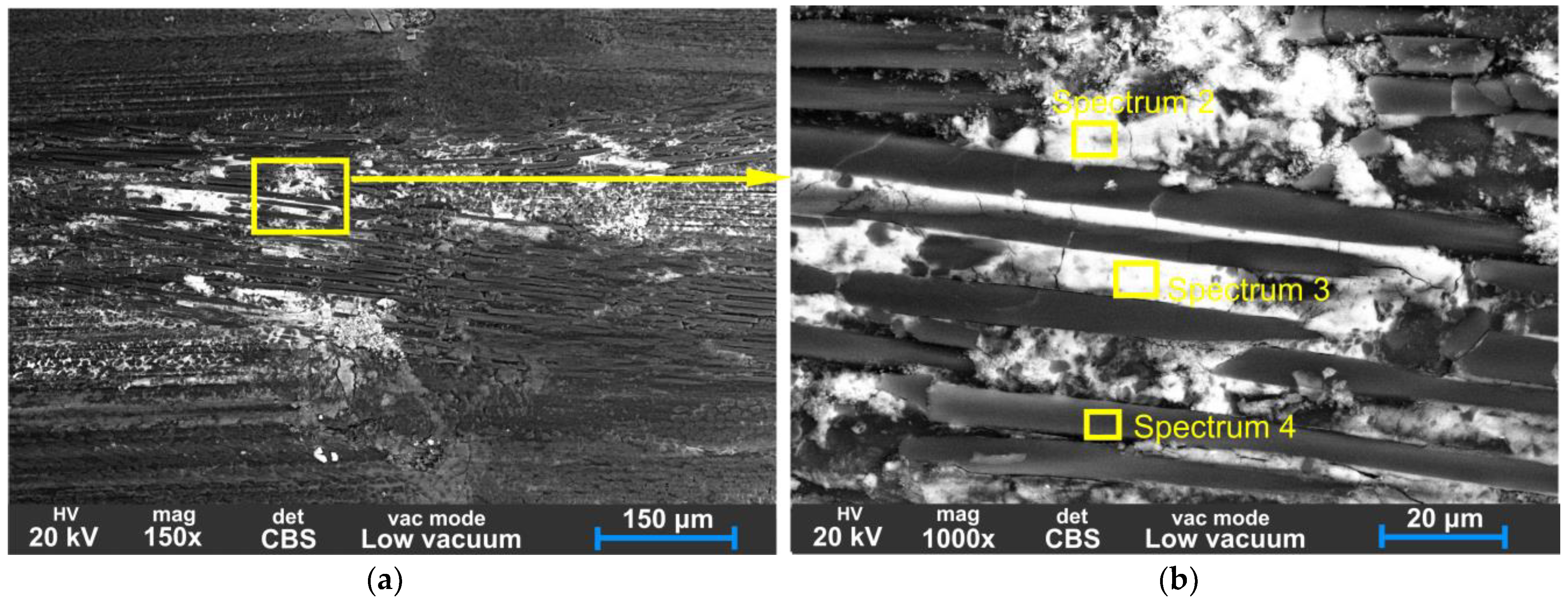
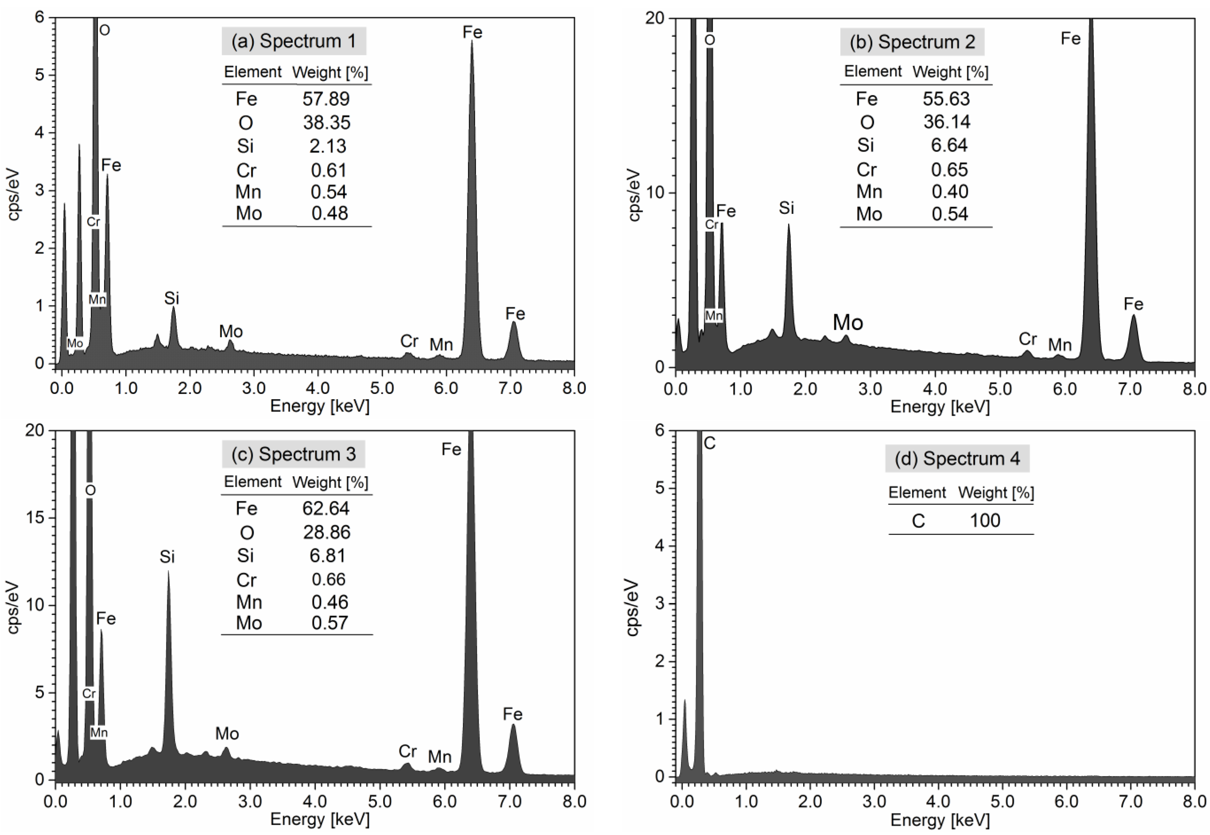
3.4. Analysis of Backscatter SEM and EDS
4. Conclusions
- The use of T700S-DT120 prepreg with incorporated toughened resin has been found to significantly enhance the durability of gears over T300-ET445 and T300-LG-900UV. This can be attributed to the higher strength fibres and toughener’s ability to improve the resistance to crack initiation and propagation during fatigue and wear. Second, the use of thinner plies results in a more complex load-sharing network, further reducing the likelihood of failure.
- The results of experimental wear study indicate nearly linear correlation between wear volume, wear pitch distance, and duration of testing. Furthermore, a consistent increase in the slope of the linear function was observed with increasing loading torque.
- The tooth profile was altered by wear, particularly in the root area, where the shape of the profile changed from an outer arched form to an inner arched shape. Numerical analysis showed that the worn out profile of CFRP gears led to a double contact with the steel pinion, heightened backlash, and elevated transmission error, negatively impacting the performance of the gears, and causing an increase in noise and vibrations and decreasing the efficiency.
- BS-SEM and EDS analysis revealed that the degradation of CFRP is due to severe adhesion and three-body wear, resulting in edge delamination caused by limited adhesion strength between the matrix and fibres. Fatigue in CFRP is typically caused by cyclic stress–strain loading, which leads to the formation of microcracks in the matrix material and eventual delamination or fibre breakage.
5. Patents
Author Contributions
Funding
Institutional Review Board Statement
Informed Consent Statement
Data Availability Statement
Conflicts of Interest
References
- Kim, M.T.; Rhee, K.Y.; Lee, J.H.; Hui, D.; Lau, A.K.T. Property Enhancement of a Carbon Fiber/Epoxy Composite by Using Carbon Nanotubes. Compos. Part B Eng. 2011, 42, 1257–1261. [Google Scholar] [CrossRef]
- Kim, B.C.; Park, D.C.; Kim, B.J.; Lee, D.G. Through-Thickness Compressive Strength of a Carbon/Epoxy Composite Laminate. Compos. Struct. 2010, 92, 480–487. [Google Scholar] [CrossRef]
- Guo, R.; Xian, G.; Li, C.; Hong, B. Effect of Fiber Hybrid Mode on the Tension–Tension Fatigue Performance for the Pultruded Carbon/Glass Fiber Reinforced Polymer Composite Rod. Eng. Fract. Mech. 2022, 260, 108208. [Google Scholar] [CrossRef]
- Jiang, Z.; Fang, Z.; Fang, C.; Li, Q.; Wang, Z. Experimental Investigation on High-Temperature Creep Behaviour of Carbon Fiber Reinforced Polymer Cable. Compos. Struct. 2022, 291, 115533. [Google Scholar] [CrossRef]
- Xian, G.; Guo, R.; Li, C.; Wang, Y. Mechanical Performance Evolution and Life Prediction of Prestressed CFRP Plate Exposed to Hygrothermal and Freeze-Thaw Environments. Compos. Struct. 2022, 293, 115719. [Google Scholar] [CrossRef]
- Handschuh, R.F.; LaBerge, K.E.; DeLuca, S.; Pelagalli, R. Vibration and Operational Characteristics of a Composite-Steel (Hybrid) Gear; NASA Center for Aerospace Information: Hanover, MD, USA, 2014. [Google Scholar]
- Catera, P.G.; Gagliardi, F.; Mundo, D.; De Napoli, L.; Matveeva, A.; Farkas, L. Multi-Scale Modeling of Triaxial Braided Composites for FE-Based Modal Analysis of Hybrid Metal-Composite Gears. Compos. Struct. 2017, 182, 116–123. [Google Scholar] [CrossRef]
- Catera, P.G.; Mundo, D.; Treviso, A.; Gagliardi, F.; Visrolia, A. On the Design and Simulation of Hybrid Metal-Composite Gears. Appl. Compos. Mater. 2019, 26, 817–833. [Google Scholar] [CrossRef]
- Blais, P.; Toubal, L. Single-Gear-Tooth Bending Fatigue of HDPE Reinforced with Short Natural Fiber. Int. J. Fatigue 2020, 141, 105857. [Google Scholar] [CrossRef]
- Mohsenzadeh, R.; Soudmand, B.H.; Shelesh-Nezhad, K. Load-Bearing Analysis of Polymer Nanocomposite Gears Using a Temperature-Based Step Loading Technique: Experimental and Numerical Study. Wear 2023, 514, 204595. [Google Scholar] [CrossRef]
- Kurokawa, M.; Uchiyama, Y.; Nagai, S. Performance of Plastic Gear Made of Carbon Fiber Reinforced Poly-Ether-Ether-Ketone: Part 2. Tribol. Int. 2000, 33, 715–721. [Google Scholar] [CrossRef]
- Kurokawa, M.; Uchiyama, Y.; Iwai, T.; Nagai, S. Performance of Plastic Gear Made of Carbon Fiber Reinforced Polyamide 12. Wear 2003, 254, 468–473. [Google Scholar] [CrossRef]
- Mao, K.; Greenwood, D.; Ramakrishnan, R.; Goodship, V.; Shrouti, C.; Chetwynd, D.; Langlois+, P. The Wear Resistance Improvement of Fibre Reinforced Polymer Composite Gears. Wear 2019, 426, 1033–1039. [Google Scholar] [CrossRef]
- Tavčar, J.; Grkman, G.; Duhovnik, J. Accelerated Lifetime Testing of Reinforced Polymer Gears. JAMDSM 2018, 12, JAMDSM0006. [Google Scholar] [CrossRef] [Green Version]
- Krairi, A.; Doghri, I.; Robert, G. Multiscale High Cycle Fatigue Models for Neat and Short Fiber Reinforced Thermoplastic Polymers. Int. J. Fatigue 2016, 92, 179–192. [Google Scholar] [CrossRef]
- Rolland, H.; Saintier, N.; Raphael, I.; Lenoir, N.; King, A.; Robert, G. Fatigue Damage Mechanisms of Short Fiber Reinforced PA66 as Observed by In-Situ Synchrotron X-Ray Microtomography. Compos. Part B Eng. 2018, 143, 217–229. [Google Scholar] [CrossRef]
- Migneault, S.; Koubaa, A.; Erchiqui, F.; Chaala, A.; Englund, K.; Krause, C.; Wolcott, M. Effect of Fiber Length on Processing and Properties of Extruded Wood-Fiber/HDPE Composites. J. Appl. Polym. Sci. 2008, 110, 1085–1092. [Google Scholar] [CrossRef] [Green Version]
- Zorko, D.; Tavčar, J.; Šturm, R.; Bergant, Z. Investigation of the Durability and Performance of Autoclave-Cured, Woven Carbon Fiber-Reinforced Polymer Composite Gears in Mesh with a Steel Pinion. Compos. Struct. 2021, 273, 114250. [Google Scholar] [CrossRef]
- Zorko, D.; Tavčar, J.; Bizjak, M.; Šturm, R.; Bergant, Z. High Cycle Fatigue Behaviour of Autoclave-Cured Woven Carbon Fibre-Reinforced Polymer Composite Gears. Polym. Test. 2021, 102, 107339. [Google Scholar] [CrossRef]
- Bijwe, J.; Sharma, M. Carbon Fabric-Reinforced Polymer Composites and Parameters Controlling Tribological Performance. In Wear of Advanced Materials; Davim, J.P., Ed.; John Wiley & Sons, Ltd.: Hoboken, NJ, USA, 2013; Volume 1, pp. 1–60. [Google Scholar]
- Ramesh, B.N.; Suresha, B. Optimization of Tribological Parameters in Abrasive Wear Mode of Carbon-Epoxy Hybrid Composites. Mater. Des. 2014, 59, 38–49. [Google Scholar] [CrossRef]
- Černe, B.; Bergant, Z.; Šturm, R.; Tavčar, J.; Zorko, D. Experimental and Numerical Analysis of Laminated Carbon Fibre-Reinforced Polymer Gears with Implicit Model for Coefficient-of-Friction Evaluation. J. Comput. Des. Eng. 2022, 9, 246–262. [Google Scholar] [CrossRef]
- Ekoi, E.J.; Dickson, A.N.; Dowling, D.P. Investigating the Fatigue and Mechanical Behaviour of 3D Printed Woven and Nonwoven Continuous Carbon Fibre Reinforced Polymer (CFRP) Composites. Compos. Part B Eng. 2021, 212, 108704. [Google Scholar] [CrossRef]
- Bergant, Z.; Savin, A.; Grum, J. Effects of Manufacturing Technology on Static, Multi-Frequency Dynamic Mechanical Analysis and Fracture Energy of Cross-Ply and Quasi-Isotropic Carbon/Epoxy Laminates. Polym. Polym. Compos. 2018, 26, 358–370. [Google Scholar] [CrossRef]
- Hoa, S.V. Principles of the Manufacturing of Composite Materials; DEStech Publications: Lancaster, UK, 2009; ISBN 978-1-932078-26-8. [Google Scholar]
- Bagheri, R.; Marouf, B.T.; Pearson, R.A. Rubber-Toughened Epoxies: A Critical Review. Polym. Rev. 2009, 49, 201–225. [Google Scholar] [CrossRef]
- Garg, A.C.; Mai, Y.-W. Failure Mechanisms in Toughened Epoxy Resins—A Review. Compos. Sci. Technol. 1988, 31, 179–223. [Google Scholar] [CrossRef]
- Sihn, S.; Kim, R.; Kawabe, K.; Tsai, S. Experimental Studies of Thin-Ply Laminated Composites. Compos. Sci. Technol. 2007, 67, 996–1008. [Google Scholar] [CrossRef]
- Galos, J. Thin-Ply Composite Laminates: A Review. Compos. Struct. 2020, 236, 111920. [Google Scholar] [CrossRef]
- Urbas, U.; Zorko, D.; Černe, B.; Tavčar, J.; Vukašinović, N. A Method for Enhanced Spur Gear Inspection Based on 3D Optical Metrology. Measurement 2020, 169, 108584. [Google Scholar] [CrossRef]
- Zorko, D.; Kulovec, S.; Tavčar, J.; Duhovnik, J. Different Teeth Profile Shapes of Polymer Gears and Comparison of Their Performance. JAMDSM 2017, 11, JAMDSM0083. [Google Scholar] [CrossRef] [Green Version]
- Černe, B.; Petkovšek, M.; Duhovnik, J.; Tavčar, J. Thermo-Mechanical Modeling of Polymer Spur Gears with Experimental Validation Using High-Speed Infrared Thermography. Mech. Mach. Theory 2020, 146, 103734. [Google Scholar] [CrossRef]
- DIN 3990; Calculation of Load Capacity of Cylindrical Gears. German National Standard: Berlin, Germany, 1987.
- Deng, H.; Li, W.; Sakai, T.; Sun, Z. Very High Cycle Fatigue Failure Analysis and Life Prediction of Cr-Ni-W Gear Steel Based on Crack Initiation and Growth Behaviours. Materials 2015, 8, 8338–8354. [Google Scholar] [CrossRef] [Green Version]
- Yadav, I.N.; Thapa, K.B. Fatigue Damage Model of Woven Glass-Epoxy Fabric Composite Materials. J. Mater. Res. Technol. 2020, 9, 301–306. [Google Scholar] [CrossRef]
- Zorko, D.; Kulovec, S.; Duhovnik, J.; Tavčar, J. Durability and Design Parameters of a Steel/PEEK Gear Pair. Mech. Mach. Theory 2019, 140, 825–846. [Google Scholar] [CrossRef]
- Basha, M.; Wagih, A.; Khan, T.; Lubineau, G.; Sebaey, T.A. On the Benefit of Thin Plies on Flexural Response of CFRP Composites Aged at Elevated Temperature. Compos. Part A Appl. Sci. Manuf. 2023, 166, 107393. [Google Scholar] [CrossRef]
- Arteiro, A.; Furtado, C.; Catalanotti, G.; Linde, P.; Camanho, P.P. Thin-Ply Polymer Composite Materials: A Review. Compos. Part A Appl. Sci. Manuf. 2020, 132, 105777. [Google Scholar] [CrossRef]


| # | Fibre Type | Fabrics Designation | Tex | Areal Density [g/m2] | Ply Thickness [mm] | Tensile Strength [MPa] | Elongation [%] | Elastic Modulus [GPa] |
|---|---|---|---|---|---|---|---|---|
| 1 | T300 | CC202 | 200 (3K) | 200 | 0.26 | 3530 | 1.5 | 230 |
| 2 | T700S | 66090P | 67 (1K) | 93 | 0.11 | 4900 | 2.1 | 230 |
| 3 | T300 | Style 469 spread | 67 (1K) | 93 | 0.11 | 3530 | 1.5 | 230 |
| Resin | Cure Temperature [°C] | Glass Transition Tg [°C] | Tensile Strength [MPa] | Elastic Modulus E [GPa] | Elongation [%] |
|---|---|---|---|---|---|
| ET445 1 | 80–150 | 135 | - | - | - |
| DT120, toughened 1 | 100–135 | 110–125 | - | - | - |
| LG 900 UV | 80–110 | 60–90 | 82 | 3.4 | 6–6.5 |
| Panel No. | Designation Fibre Resin | Plate Thickness [mm] | Stacking Sequence | Total Number of Plies | Manufacturing Process |
|---|---|---|---|---|---|
| 1 | T300-ET445 | 2.05 | [(45/0)2]s | 8 | Prepreg-AC 1 |
| 2 | T700S-DT120 | 2.02 | [(0/22.5/45/67.5)2]s | 18 | Prepreg-AC 1 |
| 3 | T300-LG 900 UV | 2.02 | [(0/22.5/45/67.5)2]s | 18 | VI-AC 2 |
| Parameter | Symbol | Value |
|---|---|---|
| Profile | - | Involute ISO 53A |
| Module | m [mm] | 1 |
| Number of teeth | Z | 20 |
| Pressure angle | α [°] | 20 |
| Profile shift coefficient—pinion | x1 | 0 |
| Profile shift coefficient—gear | x2 | 0 |
| Transverse contact ratio | εα | 1.557 |
| Mechanical Property | Value | Description |
|---|---|---|
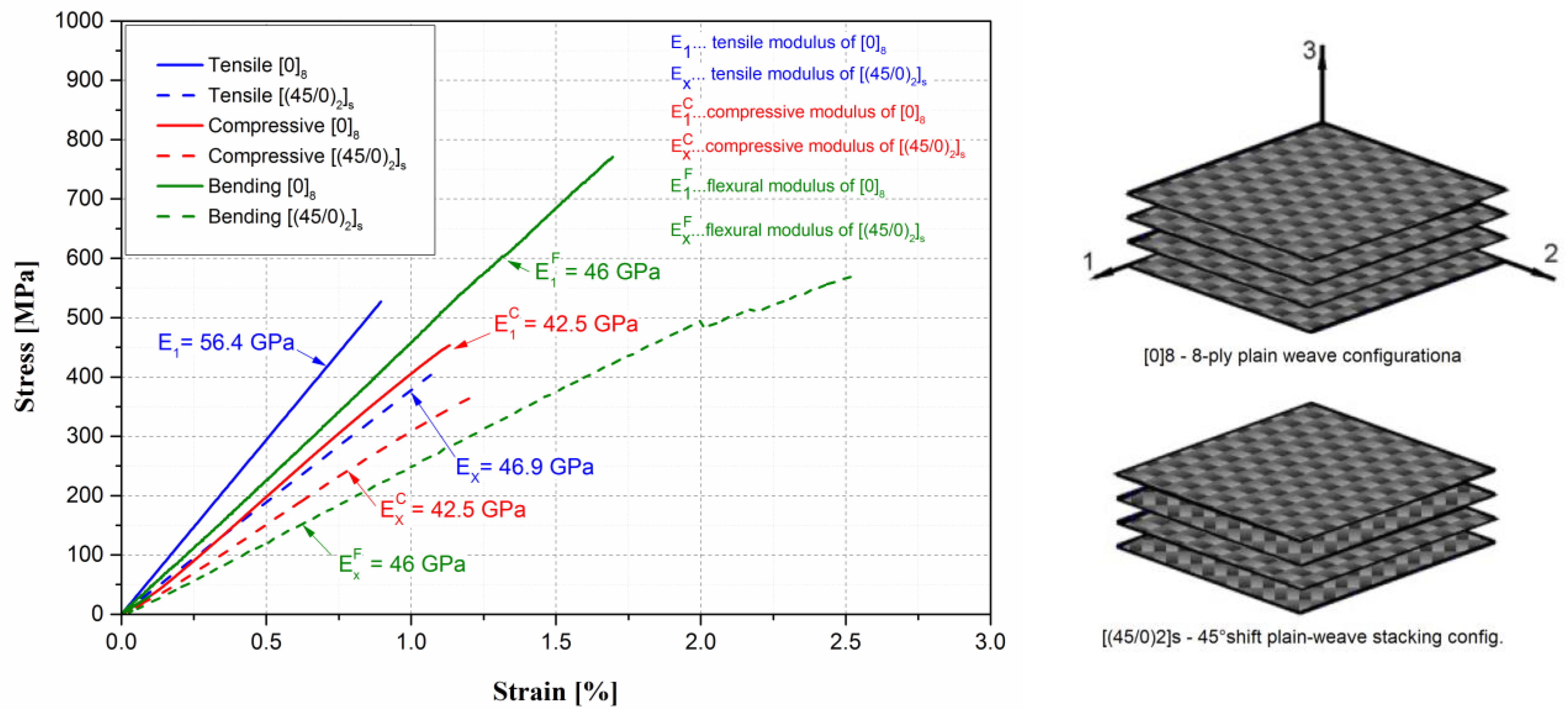
| E1= E2 [GPa] | 46.9 | Axial, transverse in-plane stiffness |
| E3 [GPa] | 6 | Transverse out-of-plane stiffness |
| 0.08 | Major Poisson ratio | |
| 0.3 | Minor Poisson ratio | |
| [GPa] | 17 | In-plane shear stiffness |
| [GPa] | 3.37 | Out-of-plane shear stiffness |
| [MPa] | 292 | Axial/y-transverse tensile strength |
| [MPa] | 50 | Transverse z-tensile strength |
| [MPa] | −217 | Axial/transverse compression strength |
| [Mpa] | −80 | Transverse compressive strength |
| 0.0095 | Axial/y-transverse tensile strain limit | |
| 0.003 | Transverse tensile z-strain limit | |
| −0.011 | Axial/y-transverse compressive strain limit | |
| −0.011 | Transverse compressive z-strain limit | |
| 0.019 | xy and xz shear strain limit | |
| 0.014 | yz shear strain limit | |
| Tg [°C] | 149 | Glass transition temperature |
| ρ [g/cm3] | 1.464 | Density |
| Torque [Nm] | Load per Gear Width [N/mm] | Root Bending Stress VDI [ΜPa] |
|---|---|---|
| 0.4 | 20 | 66 |
| 0.5 | 25 | 83 |
| 0.6 | 30 | 100 |
| 0.7 | 35 | 119 |
| 0.8 | 40 | 133 |
| 0.9 | 45 | 150 |
| Material | C | b | R2 |
|---|---|---|---|
| T700S-DT120, 93 g/m2 | 224.7 | −0.033 | 0.94 |
| T300-ET445, 200 g/m2—up to 1.2 × 10⁷ | 199.6 | −0.034 | 0.92 |
| T300-ET445, 200 g/m2—from 1 × 2 × 107 to 7 × 10⁷ | 14,220 | −0.294 | 0.86 |
| T300-LG900 UV, 93 g/m2 | 189.1 | −0.031 | 0.91 |
Disclaimer/Publisher’s Note: The statements, opinions and data contained in all publications are solely those of the individual author(s) and contributor(s) and not of MDPI and/or the editor(s). MDPI and/or the editor(s) disclaim responsibility for any injury to people or property resulting from any ideas, methods, instructions or products referred to in the content. |
© 2023 by the authors. Licensee MDPI, Basel, Switzerland. This article is an open access article distributed under the terms and conditions of the Creative Commons Attribution (CC BY) license (https://creativecommons.org/licenses/by/4.0/).
Share and Cite
Bergant, Z.; Šturm, R.; Zorko, D.; Černe, B. Fatigue and Wear Performance of Autoclave-Processed and Vacuum-Infused Carbon Fibre Reinforced Polymer Gears. Polymers 2023, 15, 1767. https://doi.org/10.3390/polym15071767
Bergant Z, Šturm R, Zorko D, Černe B. Fatigue and Wear Performance of Autoclave-Processed and Vacuum-Infused Carbon Fibre Reinforced Polymer Gears. Polymers. 2023; 15(7):1767. https://doi.org/10.3390/polym15071767
Chicago/Turabian StyleBergant, Zoran, Roman Šturm, Damijan Zorko, and Borut Černe. 2023. "Fatigue and Wear Performance of Autoclave-Processed and Vacuum-Infused Carbon Fibre Reinforced Polymer Gears" Polymers 15, no. 7: 1767. https://doi.org/10.3390/polym15071767