
Tension and Compression Properties of 3D-Printed Composites: Print Orientation and Strain Rate Effects


Abstract
:1. Introduction
2. Materials and Methods
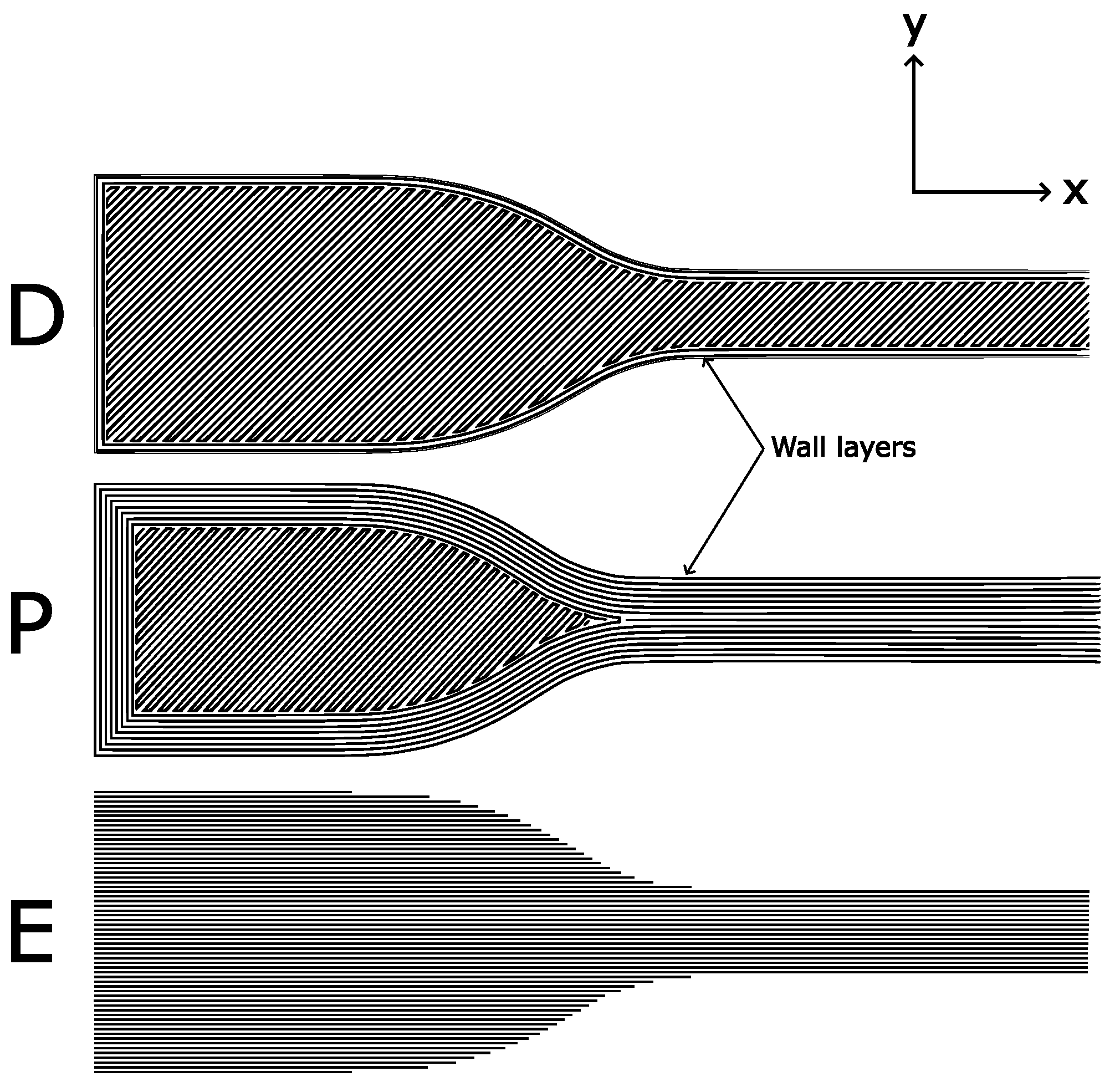
2.1. Additive Manufacture of Test Specimens
- Default parameters:
- Printed flat on the bed with two wall (outer) layers, resulting in a ±45° infill in the gauge section. Labelled ‘D’.
- Parallel:
- Printed flat on the bed with 8 wall layers. This results in a parallel infill in the gauge section. Labelled ‘P’.
- On-edge:
- Printed on its edge resulting in a print direction parallel to the loading direction for the whole sample. Labelled ‘E’.
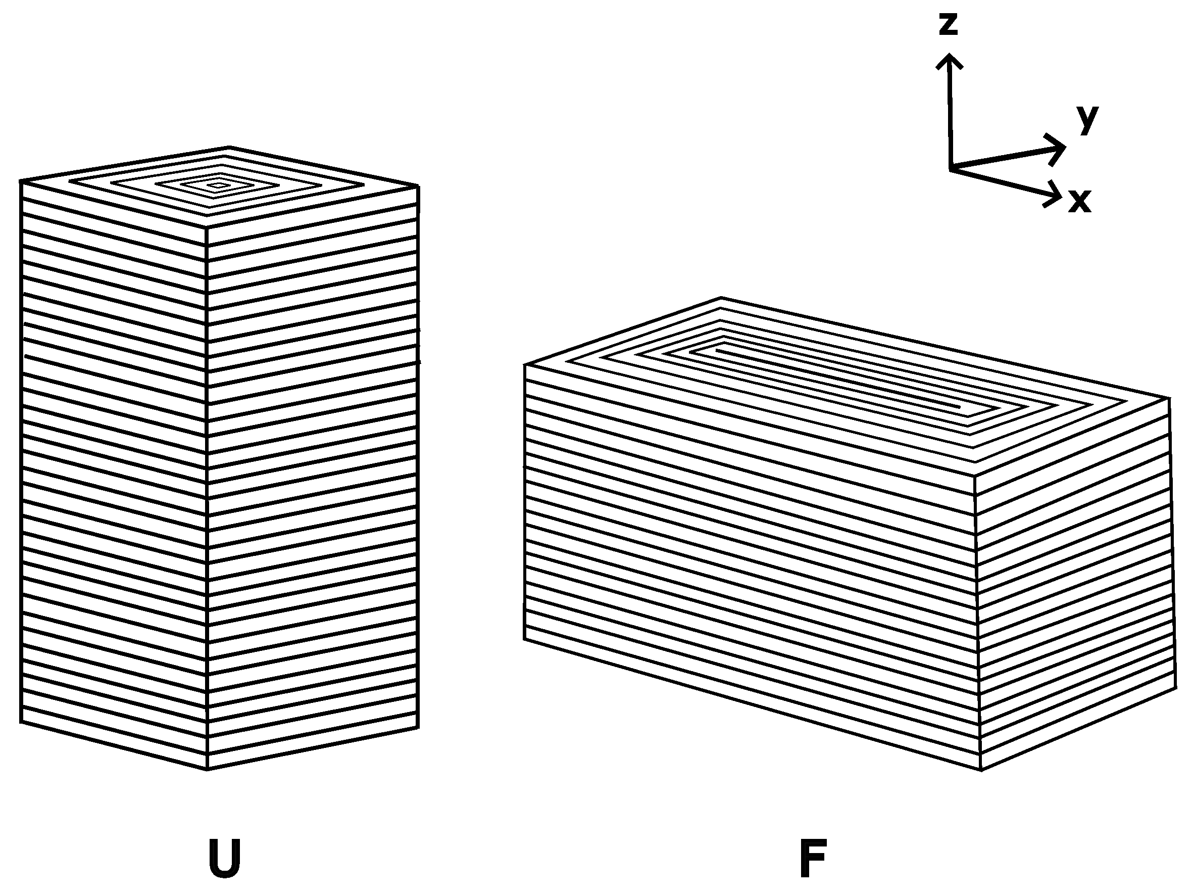
- Upright:
- Printed standing up on the bed with increased wall layers. This results in print layers being perpendicular to the loading direction. Labelled ‘U’.
- Flat:
- Printed flat on the bed with increased wall layers. This results in the print layers being parallel to the loading direction. Labelled ‘F’.
2.2. Testing
3. Results and Discussion
3.1. Tensile
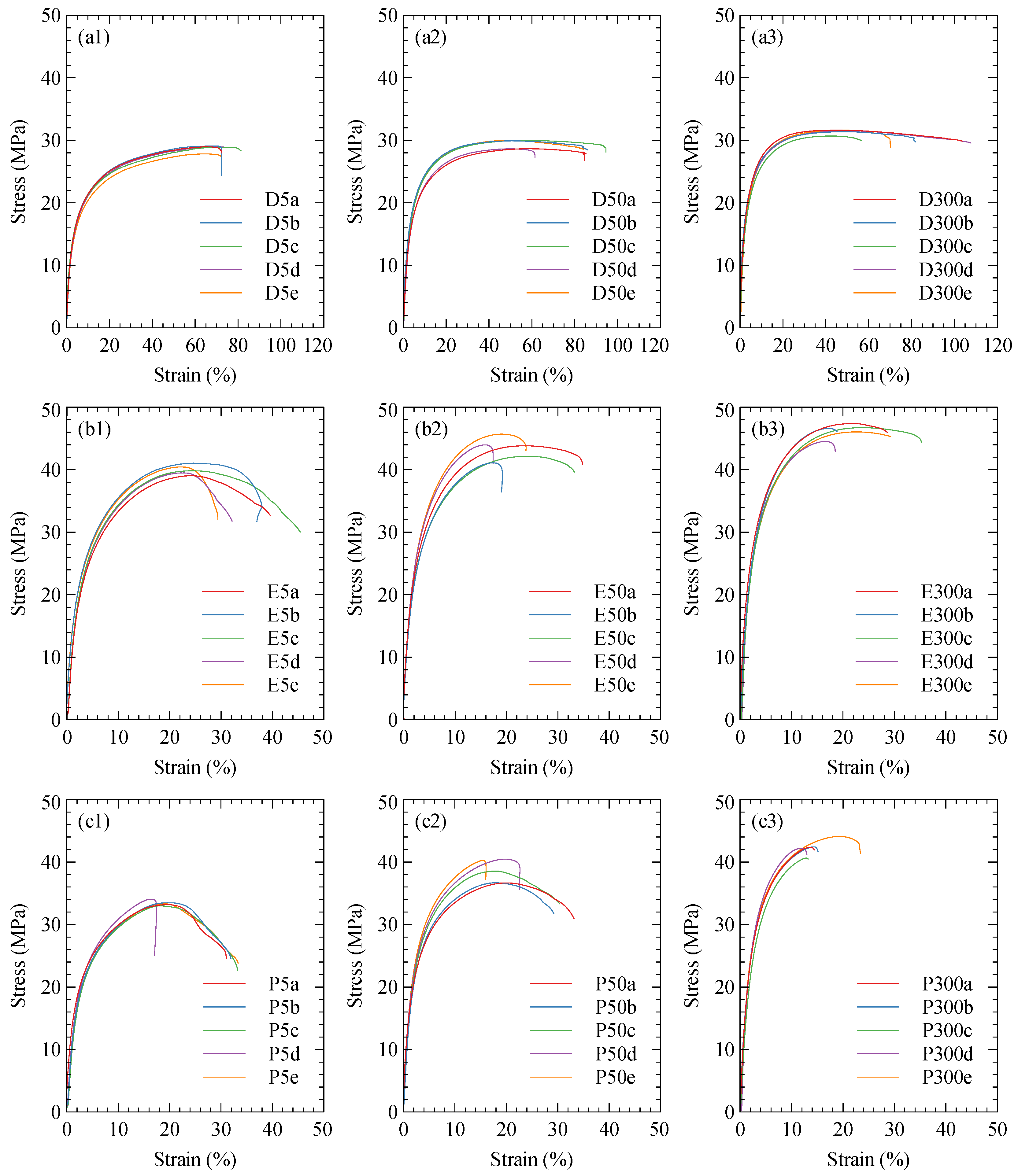
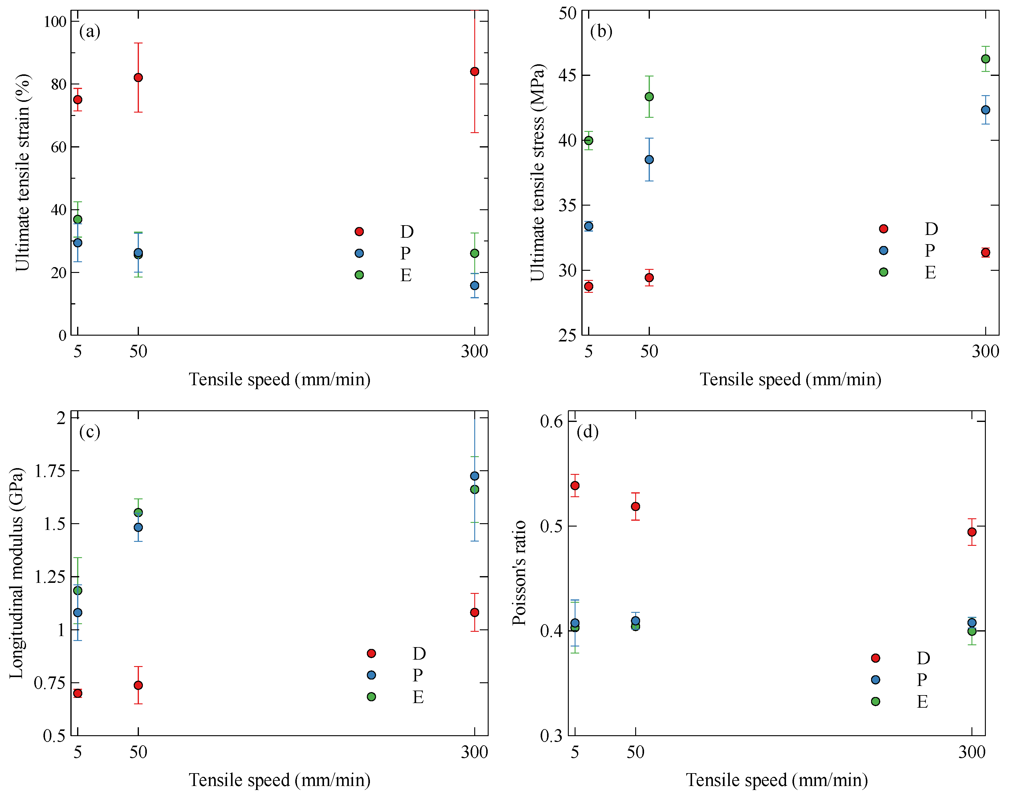
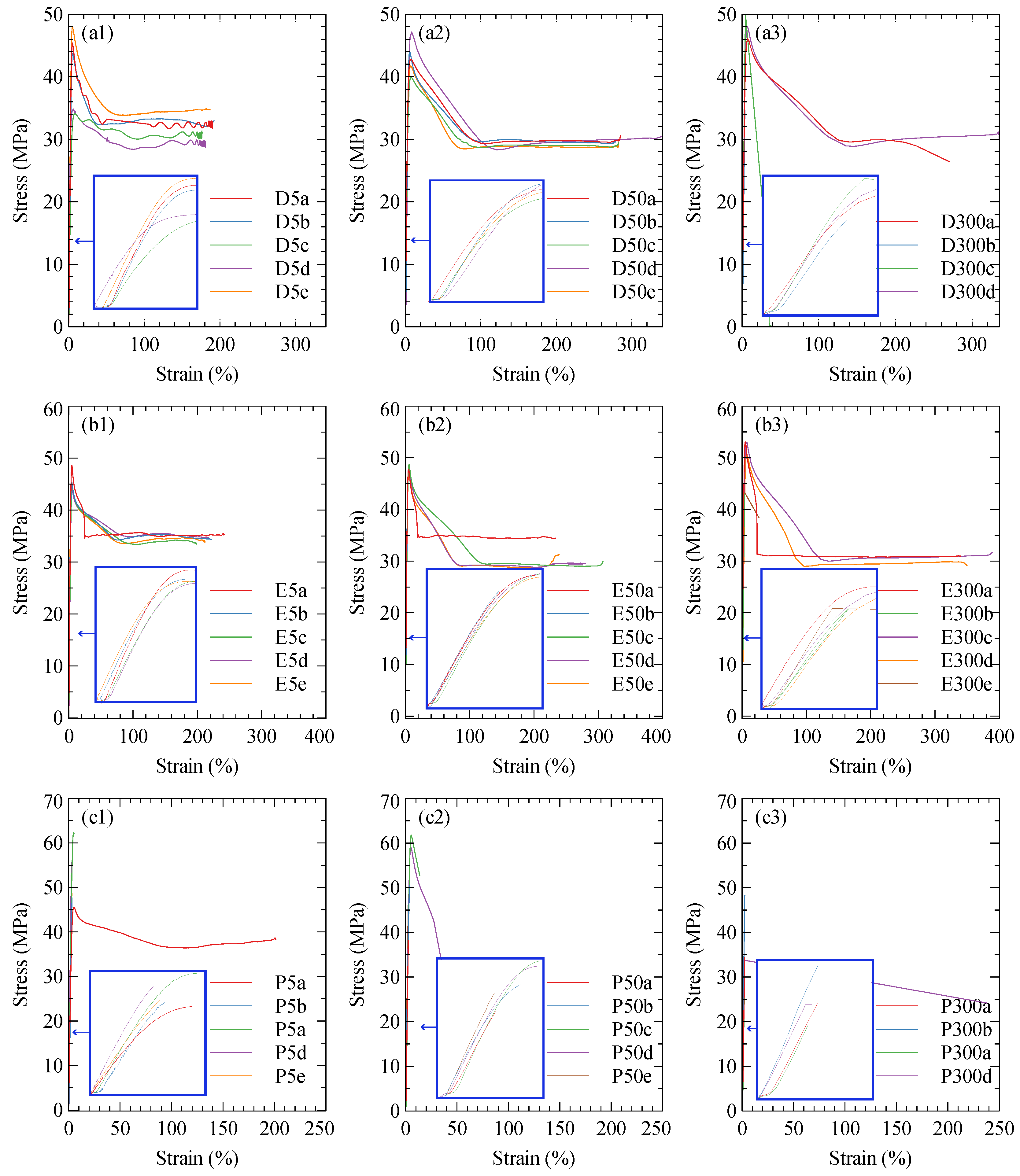
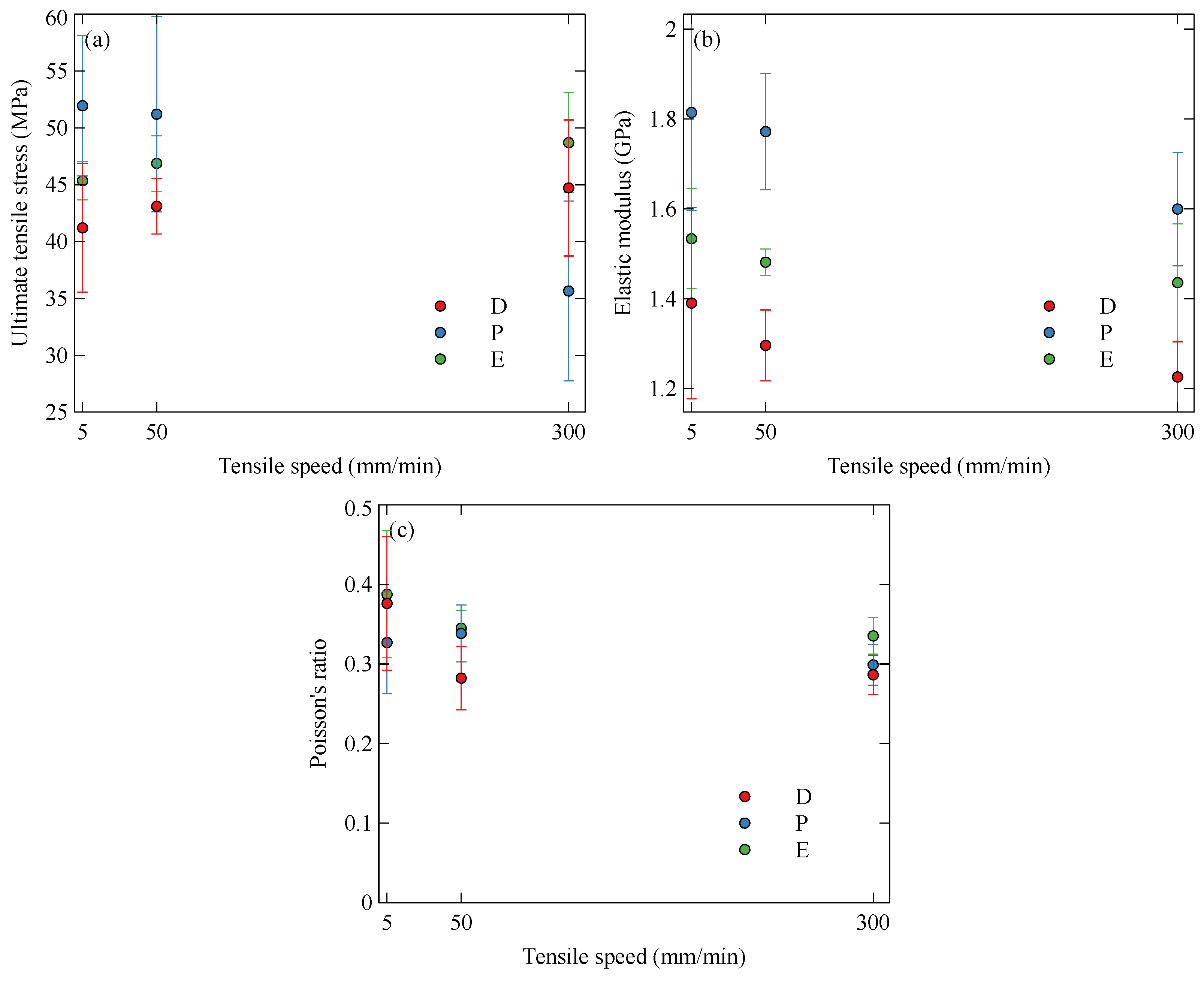
3.1.1. Onyx
3.1.2. Nylon
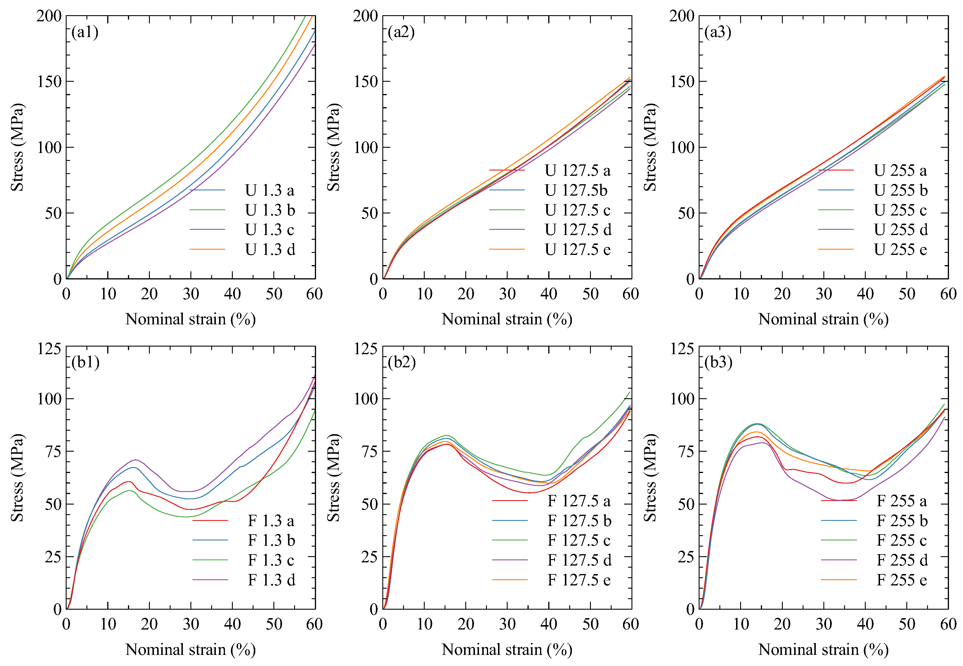
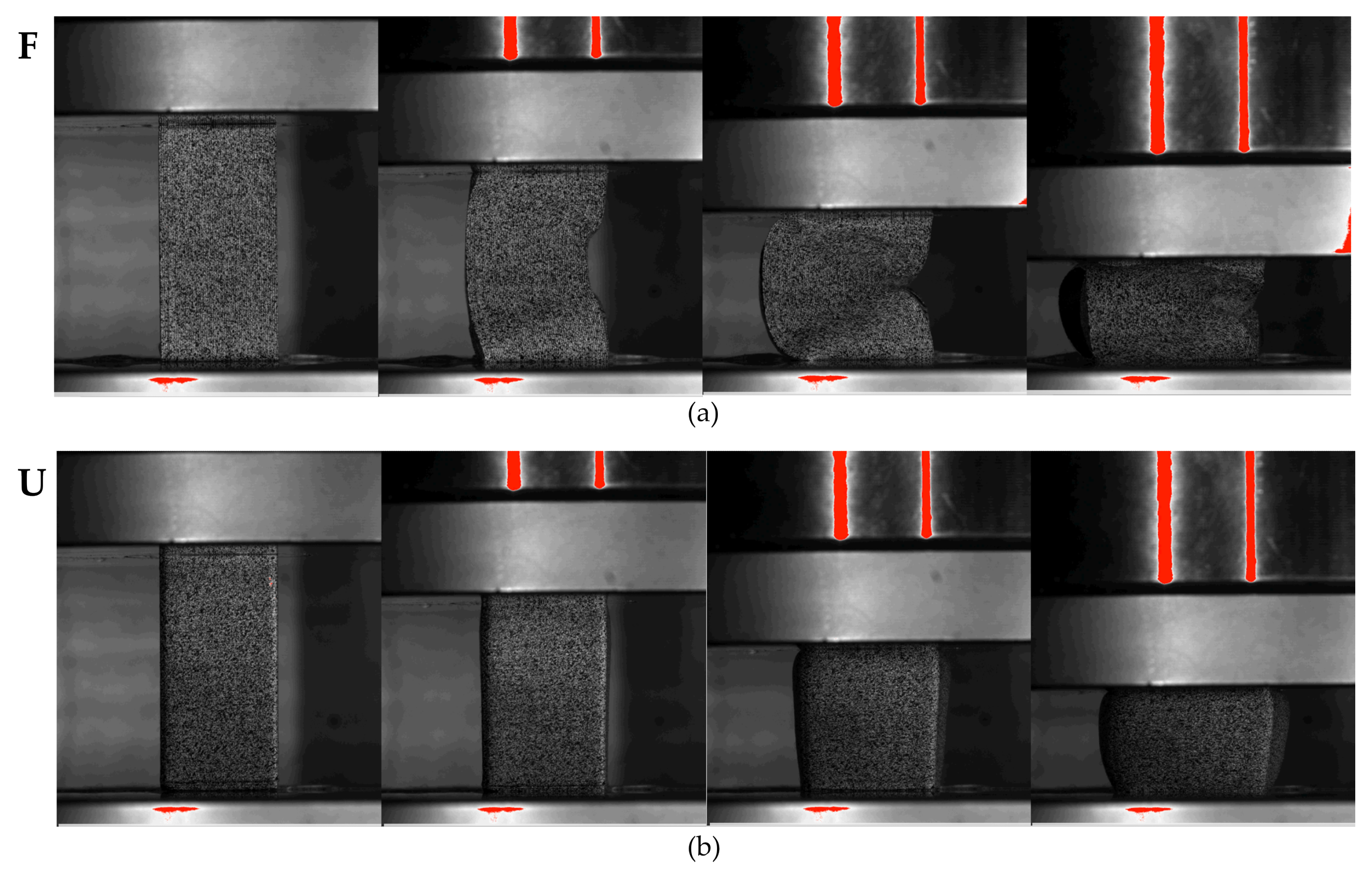
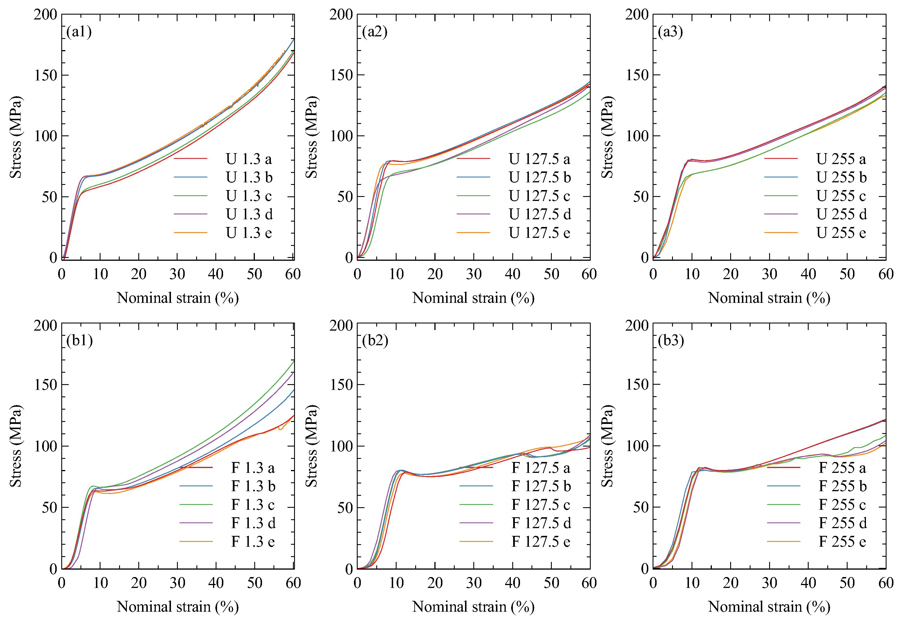
3.2. Compression
3.2.1. Onyx
3.2.2. Nylon
4. Conclusions
Author Contributions
Funding
Institutional Review Board Statement
Data Availability Statement
Conflicts of Interest
Abbreviations
| AM | Additive manufacturing |
| SLA | Stereolithography |
| SLS | Selective laser sintering |
| FFF | Fused filament fabrication |
| DIC | Digital image correlation |
| CCD | Charge-coupled device |
| UTS | Ultimate tensile stress |
References
- Sun, C.; Dong, E.; Chen, J.; Zheng, J.; Kang, J.; Jin, Z.; Liu, C.; Wang, L.; Li, D. The Promotion of Mechanical Properties by Bone Ingrowth in Additive-Manufactured Titanium Scaffolds. J. Funct. Biomater. 2022, 13, 127. [Google Scholar] [CrossRef] [PubMed]
- Xu, W.; Li, C.; Zhang, Y.; Tan, C.; Deng, C.; Li, S.; Abena, A.; Jamshidi, P.; Essa, K.; Wu, L.; et al. Mechanical property and biological behaviour of additive manufactured TiNi functionally graded lattice structure. Int. J. Extrem. Manuf. 2022, 4, 045003. [Google Scholar] [CrossRef]
- Naghavi, S.A.; Sun, C.; Hejazi, M.; Tamaddon, M.; Zheng, J.; Wang, L.; Zhang, C.; Varma, S.N.; Li, D.; Moazen, M.; et al. On the mechanical aspect of additive manufactured polyether-ether-ketone scaffold for repair of large bone defects. Biomater. Transl. 2022, 3, 142. [Google Scholar] [CrossRef] [PubMed]
- Ghofrani, A.; Taghavi, L.; Khalilivavdareh, B.; Rohani Shirvan, A.; Nouri, A. Additive manufacturing and advanced functionalities of cardiac patches: A review. Eur. Polym. J. 2022, 174, 111332. [Google Scholar] [CrossRef]
- Vasco, J.C. Additive manufacturing for the automotive industry. Addit. Manuf. 2021, 505–530. [Google Scholar] [CrossRef]
- Salifu, S.; Desai, D.; Ogunbiyi, O.; Mwale, K. Recent development in the additive manufacturing of polymer-based composites for automotive structures—A review. Int. J. Adv. Manuf. Technol. 2022, 119, 6877–6891. [Google Scholar] [CrossRef]
- Atherton Bikes. How We Build Your Bike. Available online: https://www.athertonbikes.com/technology/how-we-build-your-bike.html (accessed on 12 April 2022).
- Hexr. Manufacturing. Available online: https://hexr.com/pages/manufacturing (accessed on 12 April 2022).
- Adidas. adidas News Site|Press Resources for all Brands, Sports and Innovations: 4D. Available online: https://news.adidas.com/4d (accessed on 12 April 2022).
- LE VOLUME RÉVOLUTION DE CHANEL Extreme Volume Mascara 3d-Printed Brush 10 Noir. CHANEL. Available online: https://www.chanel.com/gb/makeup/p/191710/le-volume-revolution-de-chanel-extreme-volume-mascara-3d-printed-brush (accessed on 12 April 2022).
- Montfort. Technology|Montfort Watches. Available online: https://montfortwatches.com/pages/about (accessed on 12 April 2022).
- Gillette. Razor Maker|Gillette UK. Available online: https://www.gillette.co.uk/razor-maker.list (accessed on 12 April 2022).
- Najmon, J.C.; Raeisi, S.; Tovar, A. Review of additive manufacturing technologies and applications in the aerospace industry. Addit. Manuf. Aerosp. Ind. 2019, 7–31. [Google Scholar] [CrossRef]
- Goh, G.D.; Yap, Y.L.; Agarwala, S.; Yeong, W.Y. Recent Progress in Additive Manufacturing of Fiber Reinforced Polymer Composite. Adv. Mater. Technol. 2019, 4, 1800271. [Google Scholar] [CrossRef] [Green Version]
- Brenken, B.; Barocio, E.; Favaloro, A.; Kunc, V.; Pipes, R.B. Fused filament fabrication of fiber-reinforced polymers: A review. Addit. Manuf. 2018, 21, 1–16. [Google Scholar] [CrossRef]
- Almeida, J.H.S.; Christoff, B.G.; Tita, V.; St-Pierre, L. A concurrent fibre orientation and topology optimisation framework for 3D-printed fibre-reinforced composites. Compos. Sci. Technol. 2023, 232, 109872. [Google Scholar] [CrossRef]
- Moradi, M.; Aminzadeh, A.; Rahmatabadi, D.; Rasouli, S.A. Statistical and Experimental Analysis of Process Parameters of 3D Nylon Printed Parts by Fused Deposition Modeling: Response Surface Modeling and Optimization. J. Mater. Eng. Perform. 2021, 30, 5441–5454. [Google Scholar] [CrossRef]
- Tang, C.; Liu, J.; Yang, Y.; Liu, Y.; Jiang, S.; Hao, W. Effect of process parameters on mechanical properties of 3D printed PLA lattice structures. Compos. Part C Open Access 2020, 3, 100076. [Google Scholar] [CrossRef]
- Mishra, A.; Srivastava, V.; Kumar Gupta, N. Experimental investigation on mechanical characterization of 3D printed PLA produced by fused deposition modeling (FDM). Mater. Res. Express 2021, 8, 035304. [Google Scholar] [CrossRef]
- Maqsood, N.; Rimašauskas, M. Development and fabrication of continuous carbon fiber reinforced thermoplastic porous composite structures with different infill patterns by using additive manufacturing. J. Thermoplast. Compos. Mater. 2022, 1–26. [Google Scholar] [CrossRef]
- Yu, T.; Zhang, Z.; Song, S.; Bai, Y.; Wu, D. Tensile and flexural behaviors of additively manufactured continuous carbon fiber-reinforced polymer composites. Compos. Struct. 2019, 225, 111147. [Google Scholar] [CrossRef]
- Chacón, J.M.; Caminero, M.A.; Núñez, P.J.; García-Plaza, E.; García-Moreno, I.; Reverte, J.M. Additive manufacturing of continuous fibre reinforced thermoplastic composites using fused deposition modelling: Effect of process parameters on mechanical properties. Compos. Sci. Technol. 2019, 181, 107688. [Google Scholar] [CrossRef]
- Heidari-Rarani, M.; Rafiee-Afarani, M.; Zahedi, A.M. Mechanical characterization of FDM 3D printing of continuous carbon fiber reinforced PLA composites. Compos. Part B Eng. 2019, 175, 107147. [Google Scholar] [CrossRef]
- Li, S.; Wang, K.; Zhu, W.; Peng, Y.; Ahzi, S.; Chinesta, F. Investigation on the mechanical properties of 3D printed hybrid continuous fiber-filled composite considering influence of interfaces. Int. J. Adv. Manuf. Technol. 2022, 123, 3147–3158. [Google Scholar] [CrossRef]
- Li, L.; Liu, W.; Sun, L. Mechanical characterization of 3D printed continuous carbon fiber reinforced thermoplastic composites. Compos. Sci. Technol. 2022, 227, 109618. [Google Scholar] [CrossRef]
- Casamento, F.; Padovano, E.; Pappalardo, S.; Frache, A.; Badini, C. Development of polypropylene-based composites through fused filament fabrication: The effect of carbon-based fillers. Compos. Part A Appl. Sci. Manuf. 2023, 164, 107308. [Google Scholar] [CrossRef]
- Peng, X.; Zhang, M.; Guo, Z.; Sang, L.; Hou, W. Investigation of processing parameters on tensile performance for FDM-printed carbon fiber reinforced polyamide 6 composites. Compos. Commun. 2020, 22, 100478. [Google Scholar] [CrossRef]
- Bakis, C.E.; Haluza, R.T.; Bartolai, J.; Kim, J.J.; Simpson, T.W. Assessment of anisotropic mechanical properties of a 3D printed carbon whisker reinforced composite. Adv. Compos. Mater. 2019, 28, 545–560. [Google Scholar] [CrossRef]
- Abderrafai, Y.; Diouf-Lewis, A.; Sosa-Rey, F.; Farahani, R.D.; Piccirelli, N.; Lévesque, M.; Therriault, D. Additive manufacturing and characterization of high temperature thermoplastic blends for potential aerospace applications. Compos. Sci. Technol. 2023, 231, 109839. [Google Scholar] [CrossRef]
- Yasa, E.; Ersoy, K. Dimensional Accuracy and Mechanical Properties of Chopped Carbon Reinforced Polymers Produced by Material Extrusion Additive Manufacturing. Materials 2019, 12, 3885. [Google Scholar] [CrossRef] [PubMed] [Green Version]
- Mulholland, T.; Goris, S.; Boxleitner, J.; Osswald, T.A.; Rudolph, N. Fiber Orientation Effects in Fused Filament Fabrication of Air-Cooled Heat Exchangers. JOM 2018, 70, 298–302. [Google Scholar] [CrossRef]
- Isobe, T.; Tanaka, T.; Nomura, T.; Yuasa, R. Comparison of strength of 3D printing objects using short fiber and continuous long fiber. IOP Conf. Ser. Mater. Sci. Eng. 2018, 406, 012042. [Google Scholar] [CrossRef]
- Eiger. Eiger 3D Printing Software|Markforged. Available online: https://eiger.io (accessed on 27 May 2021).
- Gowtham, H.L.; Pothnis, J.R.; Ravikumar, G.; Naik, N.K. High strain rate in-plane shear behavior of composites. Polym. Test. 2013, 32, 1334–1341. [Google Scholar] [CrossRef]
- Kim, H.; Kim, G.; Lee, S.; Son, M.; Choe, G.; Nam, J. Strain rate effects on the compressive and tensile behavior of bundle-type polyamide fiber-reinforced cementitious composites. Compos. Part B Eng. 2019, 160, 50–65. [Google Scholar] [CrossRef]
- Mohsin, M.A.A.; Iannucci, L.; Greenhalgh, E.S. On the Dynamic Tensile Behaviour of Thermoplastic Composite Carbon/Polyamide 6.6 Using Split Hopkinson Pressure Bar. Materials 2021, 14, 1653. [Google Scholar] [CrossRef] [PubMed]
- Abdo, D.; Gleadall, A.; Silberschmidt, V.V. Failure behaviour of short-fibre-reinforced PBT composites: Effect of strain rate. Eng. Fail. Anal. 2019, 105, 466–476. [Google Scholar] [CrossRef]
- Ochola, R.O.; Marcus, K.; Nurick, G.N.; Franz, T. Mechanical behaviour of glass and carbon fibre reinforced composites at varying strain rates. Compos. Struct. 2004, 63, 455–467. [Google Scholar] [CrossRef]


| Test Type | Crosshead Speed (mm/min) | Nominal Strain Rate (1/min) |
| 5 | 0.15 | |
| Tensile | 50 | 1.5 |
| 300 | 9 | |
| 1.3 | 0.05 | |
| Compressive | 127.5 | 5 |
| 255 | 10 |
| Material | Orientation | Test Speed (mm/min) | E (GPa) | UTS (MPa) | |
|---|---|---|---|---|---|
| Nylon | Default | 5 | 1.39 ± 0.21 | 0.37 ± 0.08 | 41.21 ± 5.67 |
| 50 | 1.30 ± 0.08 | 0.28 ± 0.04 | 43.11 ± 2.44 | ||
| 300 | 1.23 ±0.08 | 0.29 ± 0.02 | 44.72 ± 5.98 | ||
| Parallel | 5 | 1.81 ± 0.22 | 0.33 ± 0.06 | 51.95 ± 6.18 | |
| 50 | 1.77 ± 0.13 | 0.34 ± 0.04 | 51.21 ± 8.59 | ||
| 300 | 1.56 ± 0.13 | 0.30 ± 0.03 | 35.65 ± 7.91 | ||
| On-edge | 5 | 1.53 ± 0.11 | 0.39 ± 0.08 | 45.35 ± 1.69 | |
| 50 | 1.48 ± 0.03 | 0.34 ± 0.02 | 46.88 ± 2.44 | ||
| 300 | 1.44 ± 0.13 | 0.34 ± 0.02 | 48.71 ± 4.39 | ||
| Onyx | Default | 5 | 0.70 ± 0.02 | 0.54 ± 0.01 | 28.75 ± 0.46 |
| 50 | 0.74 ± 0.09 | 0.52 ± 0.01 | 29.42 ± 0.64 | ||
| 300 | 1.08 ± 0.09 | 0.49 ± 0.01 | 31.36 ± 0.35 | ||
| Parallel | 5 | 1.08 ± 0.13 | 0.40 ± 0.02 | 33.39 ± 0.37 | |
| 50 | 1.48 ± 0.07 | 0.40 ± 0.00 | 38.51 ± 1.65 | ||
| 300 | 1.73 ± 0.31 | 0.40 ± 0.01 | 42.34 ± 1.10 | ||
| On-edge | 5 | 1.18 ± 0.16 | 0.41 ± 0.02 | 39.98 ± 0.71 | |
| 50 | 1.55 ± 0.07 | 0.41 ± 0.01 | 43.35 ± 1.59 | ||
| 300 | 1.66 ± 0.16 | 0.41 ± 0.01 | 46.26 ± 0.97 |
| Material | Orientation | Test Speed (mm/min) | E (GPa) | |
|---|---|---|---|---|
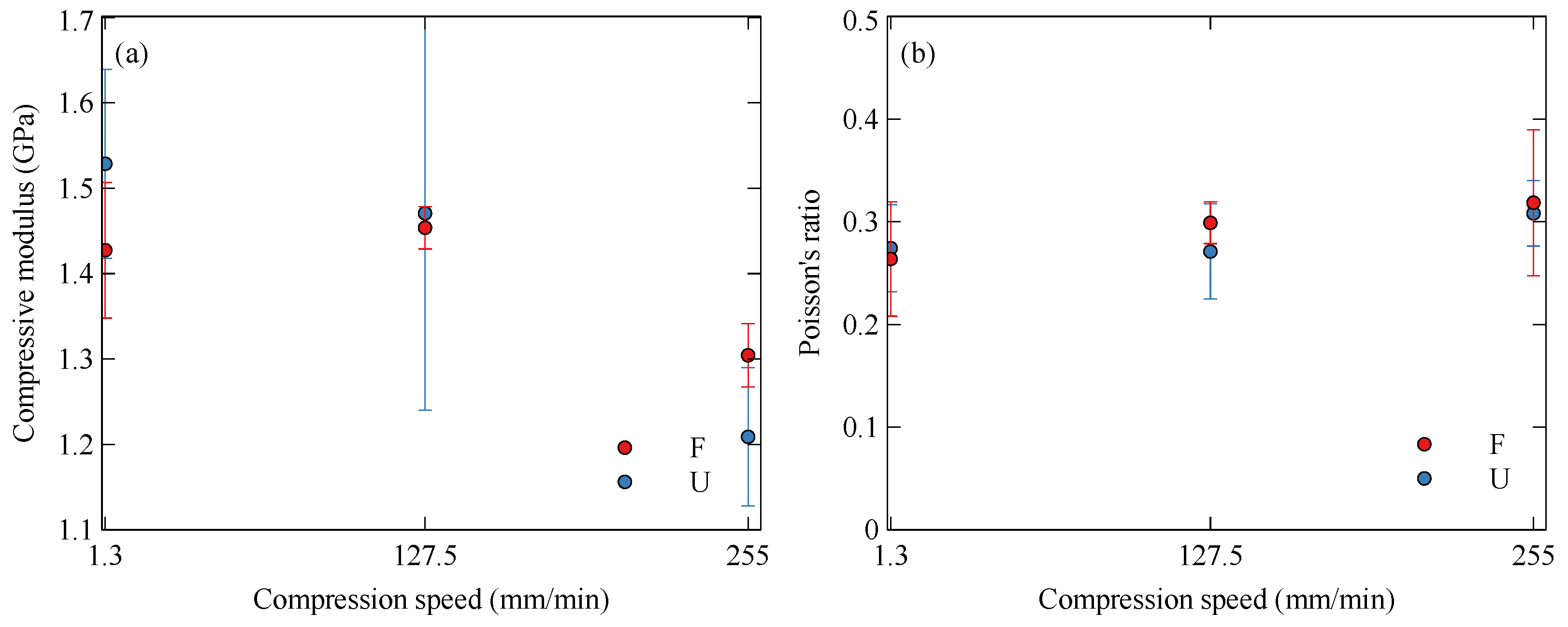
| Nylon | Flat | 1.3 | 1.43 ± 0.08 | 0.26 ± 0.06 |
| 127.5 | 1.45 ± 0.02 | 0.30 ± 0.02 | ||
| 255 | 1.30 ± 0.04 | 0.32 ± 0.07 | ||
| Upright | 1.3 | 1.53 ± 0.11 | 0.27 ± 0.04 | |
| 127.5 | 1.47 ± 0.23 | 0.27 ± 0.05 | ||
| 255 | 1.21 ± 0.08 | 0.31 ± 0.03 | ||
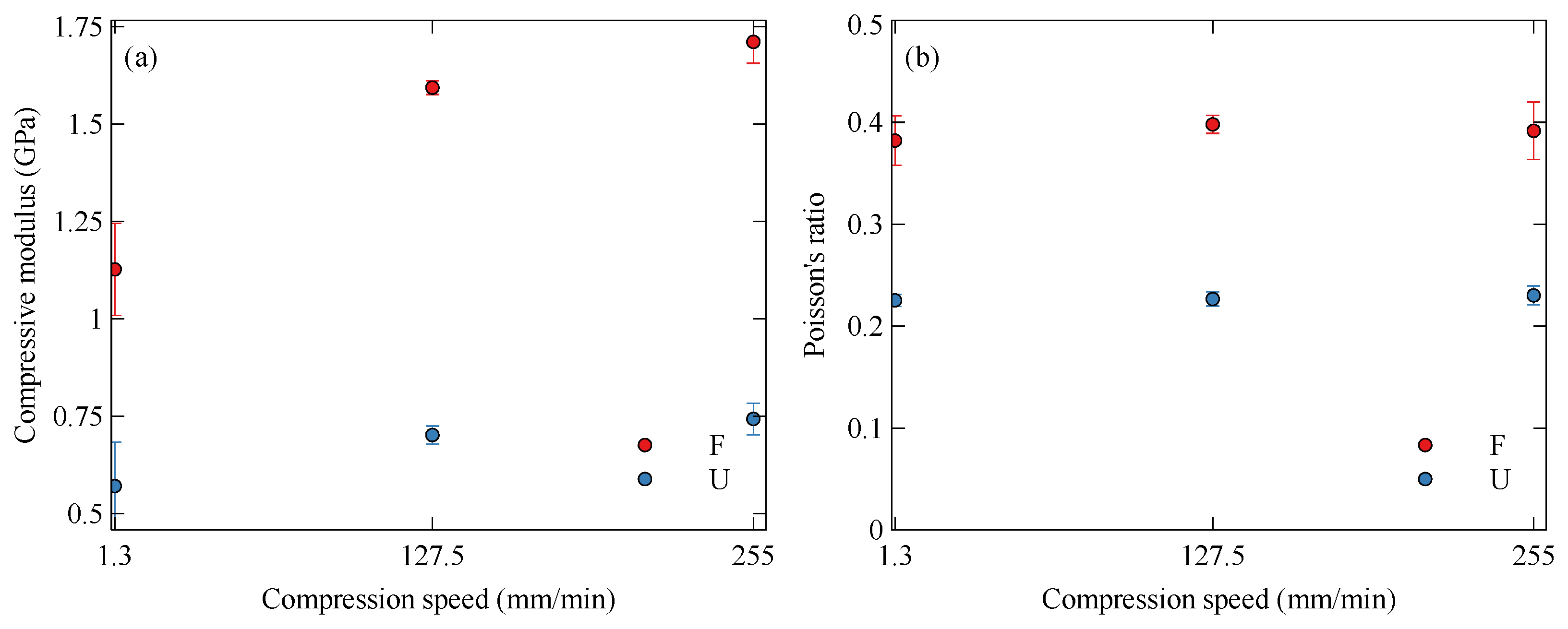
| Onyx | Flat | 1.3 | 1.13 ± 0.12 | 0.38 ± 0.02 |
| 127.5 | 1.59 ± 0.02 | 0.40 ± 0.01 | ||
| 255 | 1.71 ± 0.05 | 0.39 ± 0.03 | ||
| Upright | 1.3 | 0.57 ± 0.11 | 0.22 ± 0.01 | |
| 127.5 | 0.70 ± 0.02 | 0.22 ± 0.01 | ||
| 255 | 0.74 ± 0.04 | 0.23 ± 0.01 |
Disclaimer/Publisher’s Note: The statements, opinions and data contained in all publications are solely those of the individual author(s) and contributor(s) and not of MDPI and/or the editor(s). MDPI and/or the editor(s) disclaim responsibility for any injury to people or property resulting from any ideas, methods, instructions or products referred to in the content. |
© 2023 by the authors. Licensee MDPI, Basel, Switzerland. This article is an open access article distributed under the terms and conditions of the Creative Commons Attribution (CC BY) license (https://creativecommons.org/licenses/by/4.0/).
Share and Cite
Fisher, T.; Almeida Jr, J.H.S.; Falzon, B.G.; Kazancı, Z. Tension and Compression Properties of 3D-Printed Composites: Print Orientation and Strain Rate Effects. Polymers 2023, 15, 1708. https://doi.org/10.3390/polym15071708
Fisher T, Almeida Jr JHS, Falzon BG, Kazancı Z. Tension and Compression Properties of 3D-Printed Composites: Print Orientation and Strain Rate Effects. Polymers. 2023; 15(7):1708. https://doi.org/10.3390/polym15071708
Chicago/Turabian StyleFisher, Tom, José Humberto S. Almeida Jr, Brian G. Falzon, and Zafer Kazancı. 2023. "Tension and Compression Properties of 3D-Printed Composites: Print Orientation and Strain Rate Effects" Polymers 15, no. 7: 1708. https://doi.org/10.3390/polym15071708