
A Mini Review on the Development of Conjugated Polymers: Steps towards the Commercialization of Organic Solar Cells
 ,
,  , ,
, ,  ,
, 
Abstract
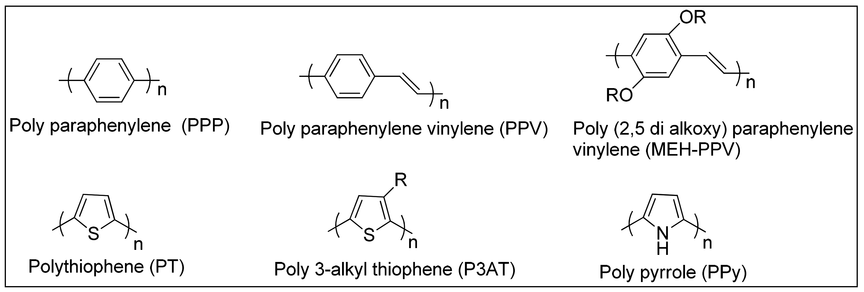
:1. Background
2. Application of Conjugated Polymers
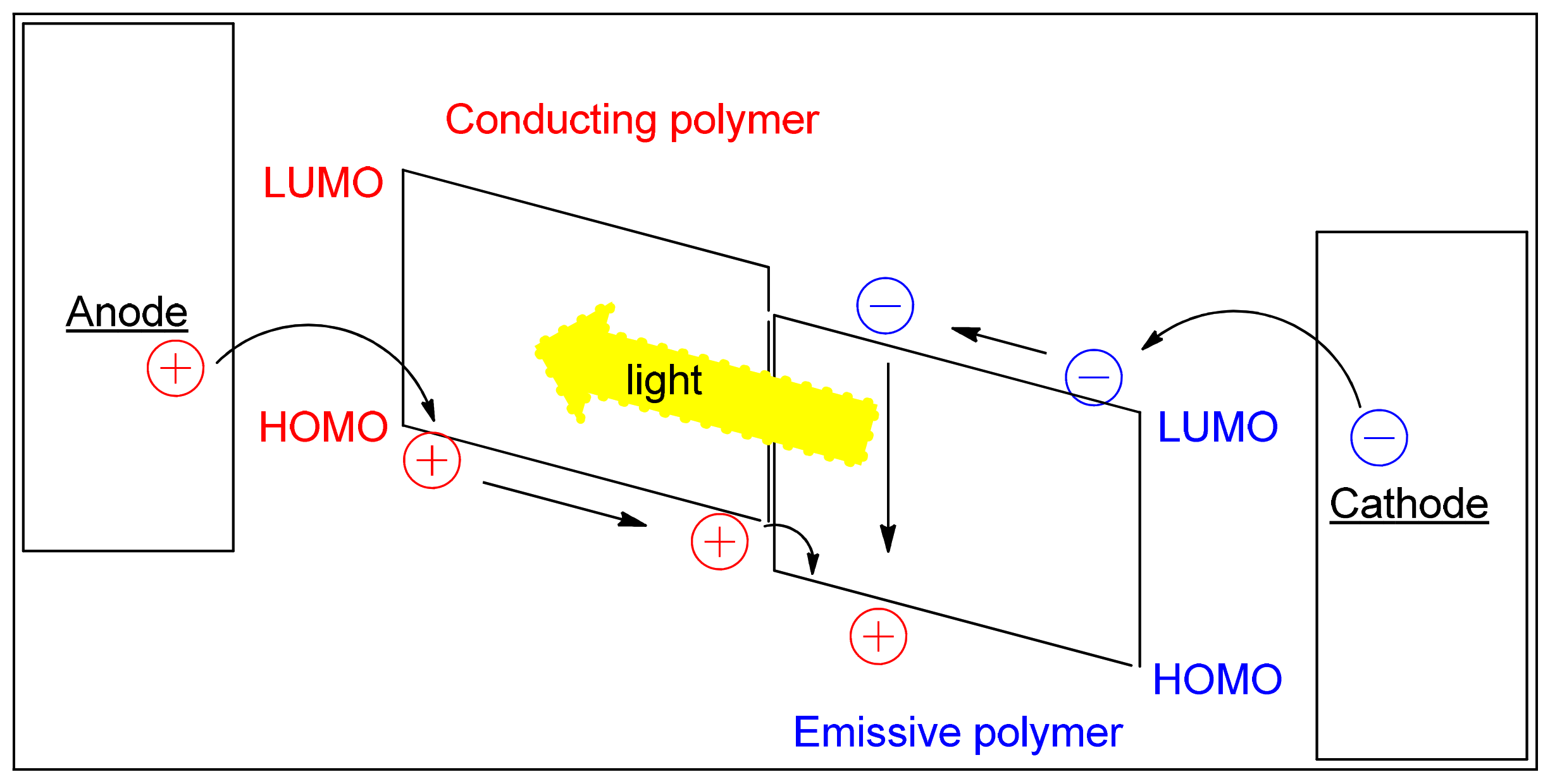
2.1. Light-Emitting Diodes
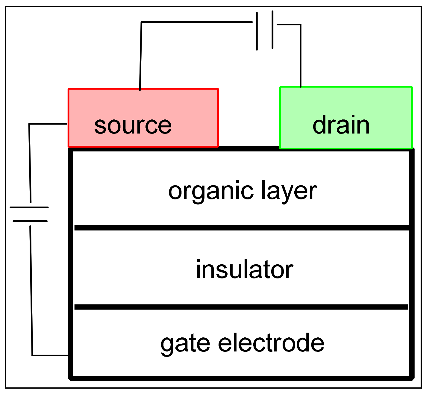
2.2. Field-Effect Transistors (FET)
3. Architecture of Organic Solar Cells
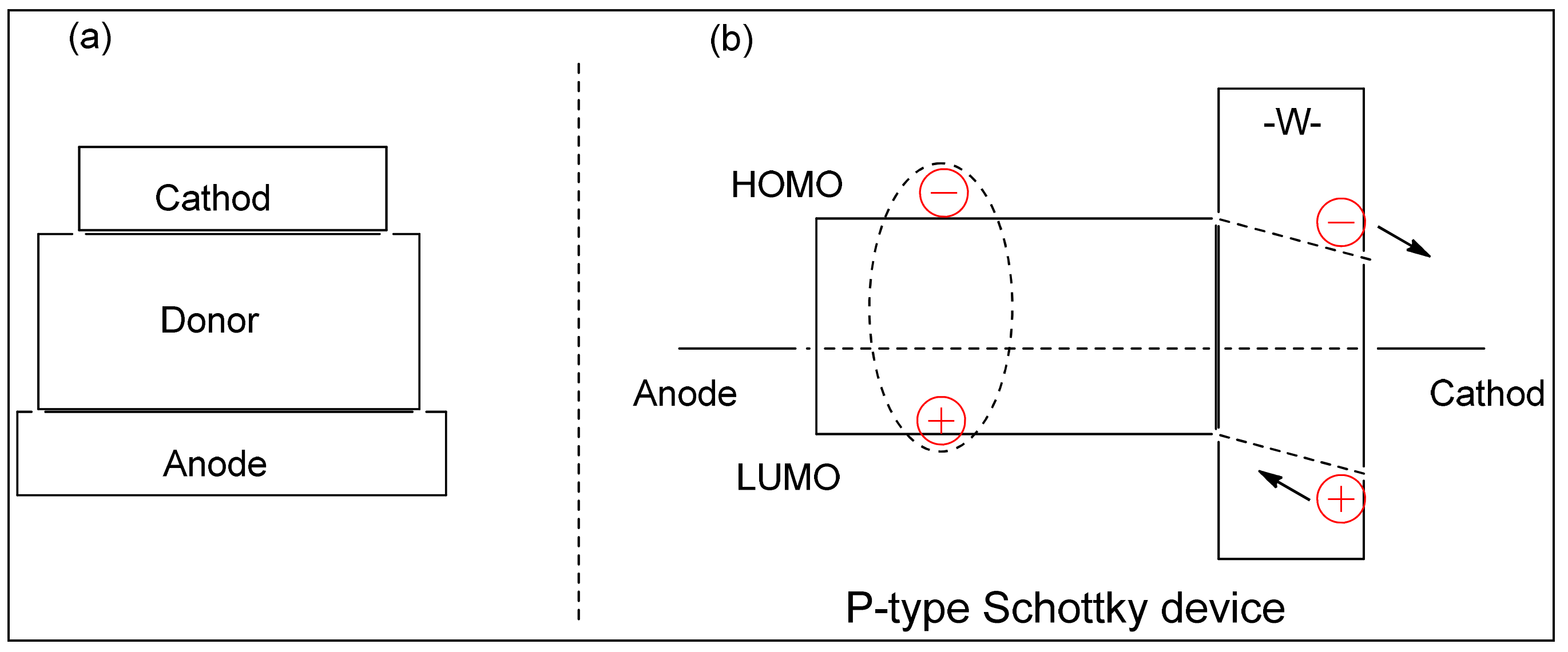
3.1. Single-Layer Device
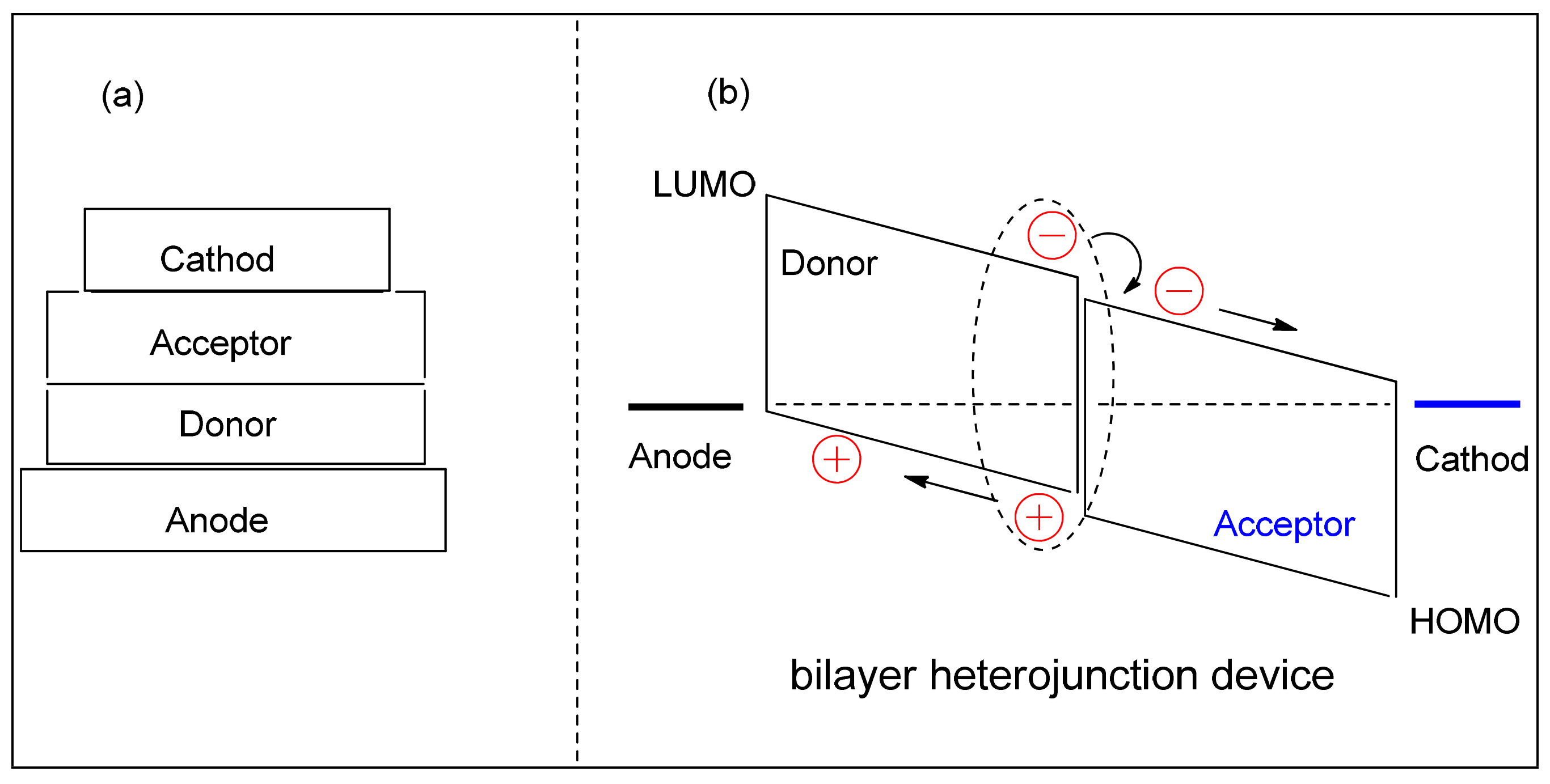
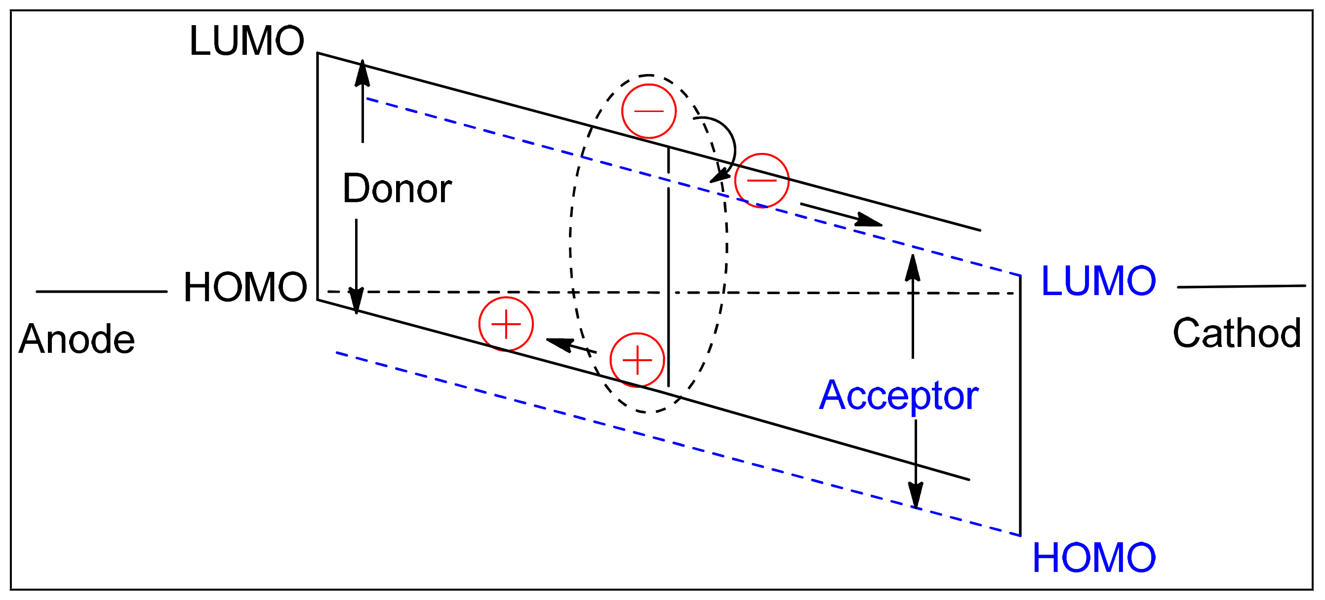
3.2. Bilayer Device
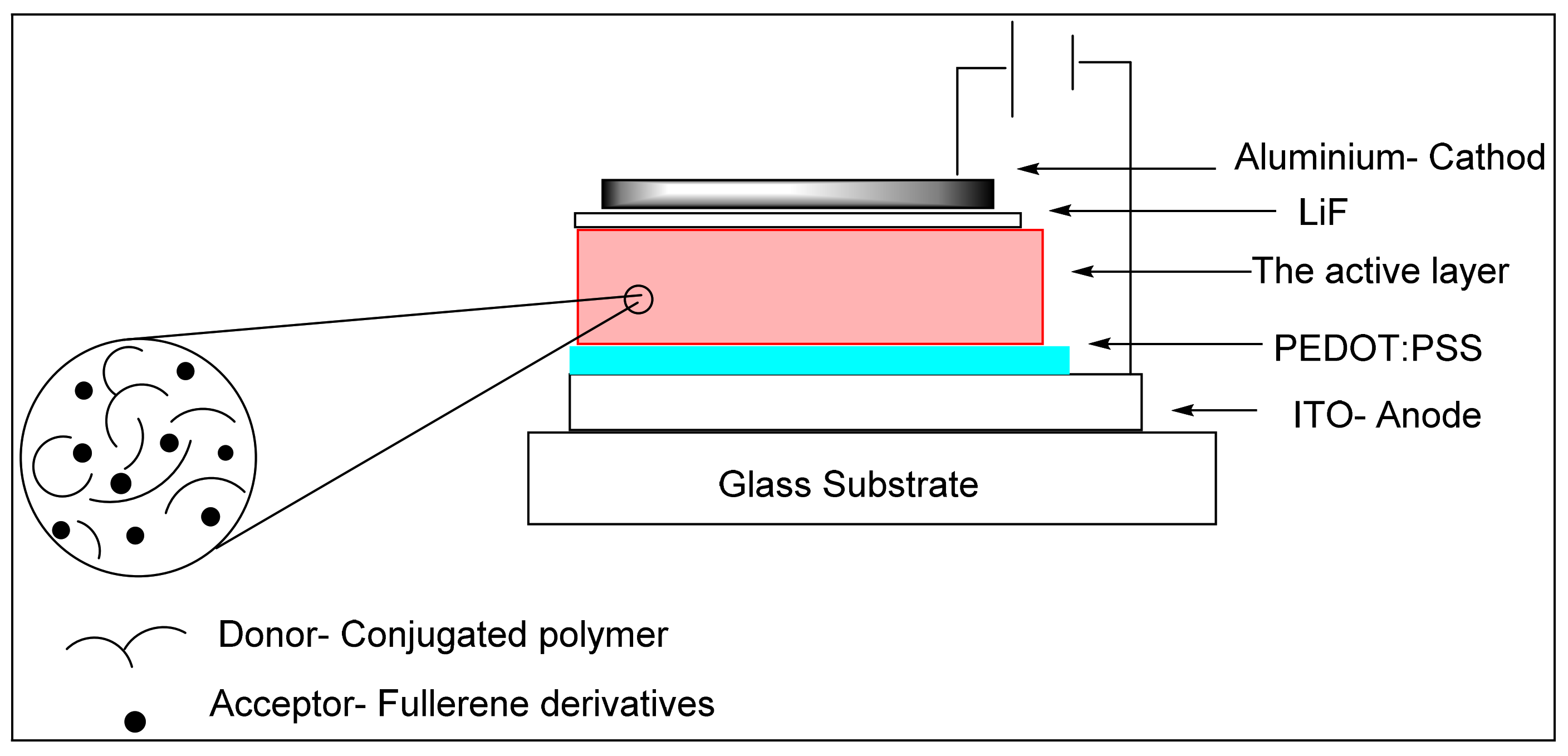
3.3. Bulk Heterojunction (BHJ) Device
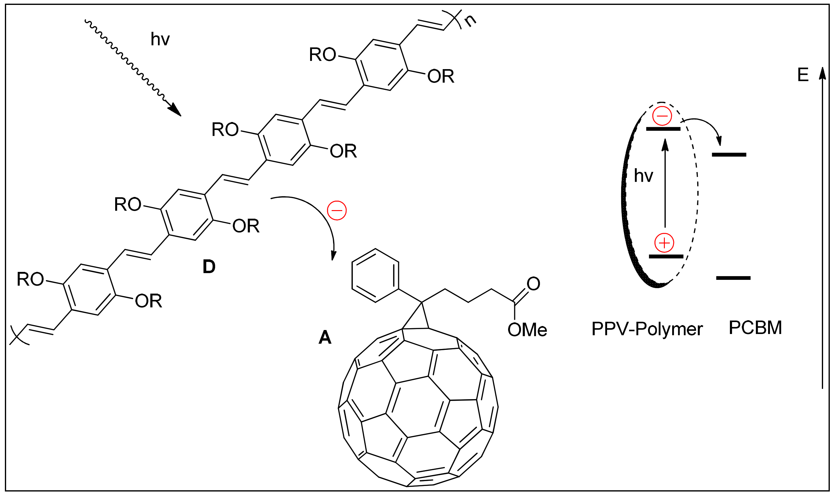
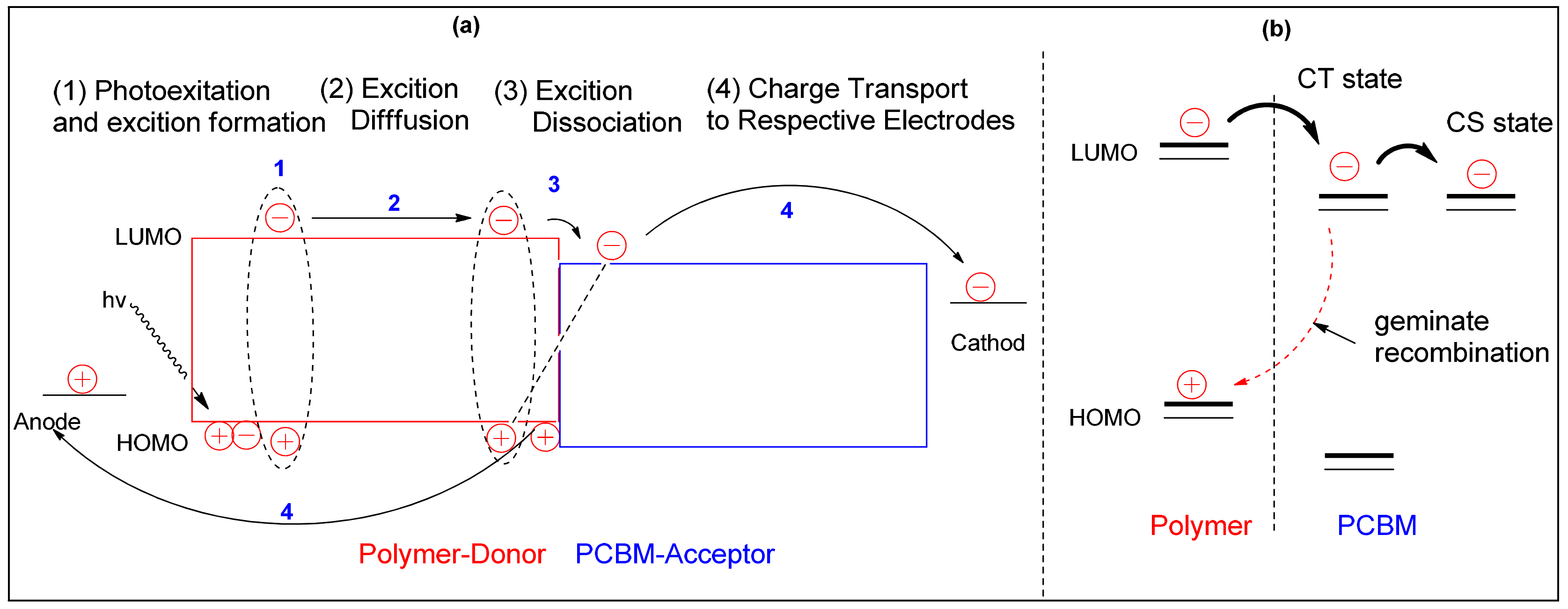
4. Basic Operating Principles of Organic Solar Cells
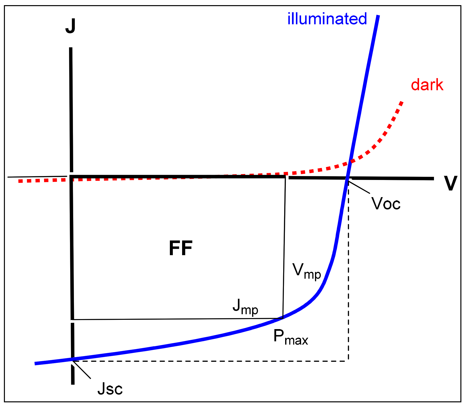
5. Characterization of Organic Solar Cells
6. Molecular Engineering of Conjugated Polymers
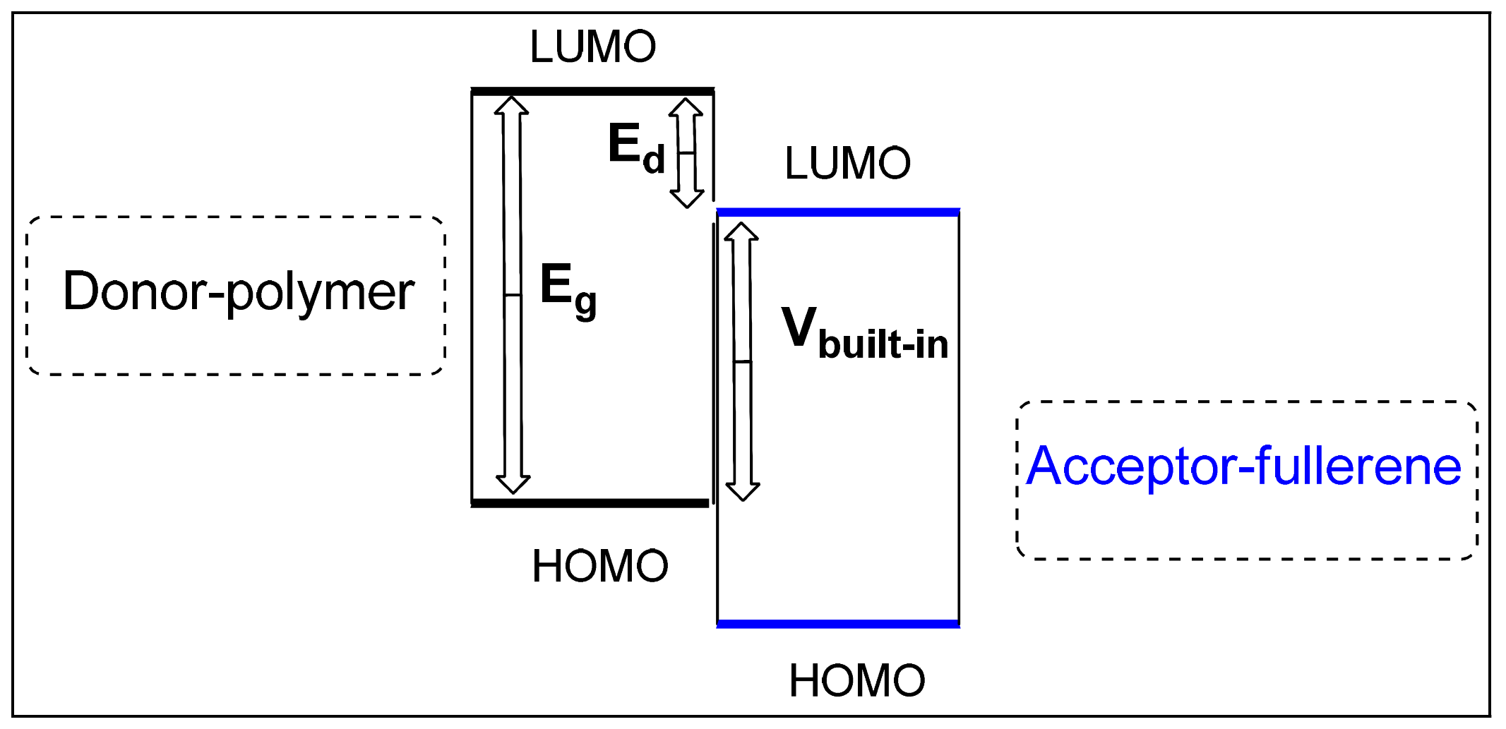
6.1. Requirement of EBG and Energy Levels
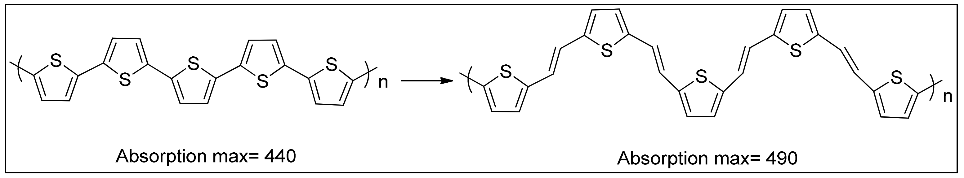
6.2. EBG Engineering of Conjugated Polymer
6.3. Donor–Acceptor Alternation Approach in Conjugated Polymer
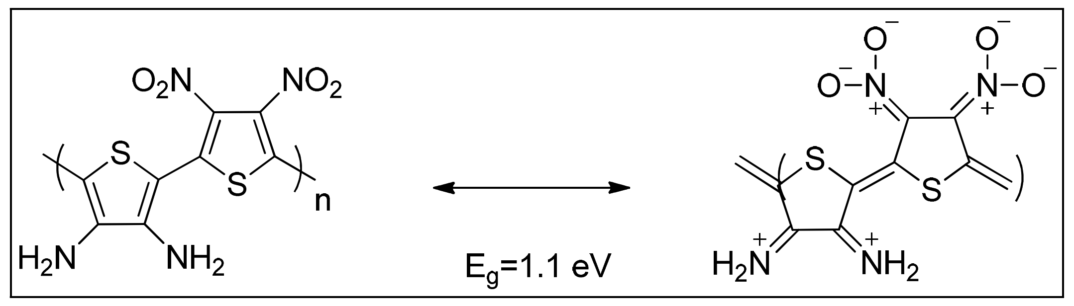
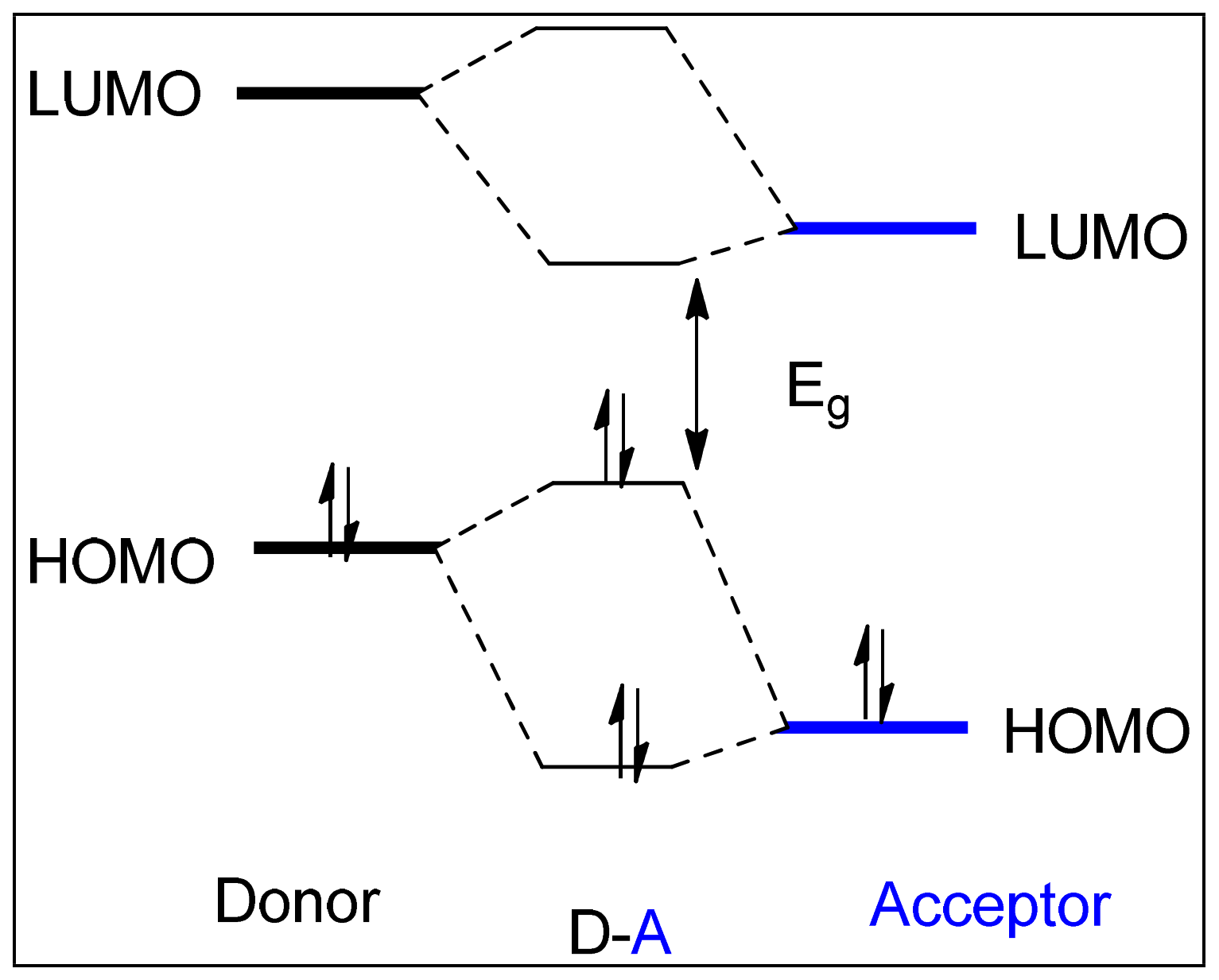
 D+ = A−) over the polymer’s main backbone, resulting in reduced optical EBG [29]. Moreover, it is assumed that ICT between the donor-HOMO and acceptor-LUMO reduces the energy EBG of the polymer, leading to a significant reduction in the EBG owing to improved interchain delocalization. The decreased EBG energy can be rationalized and explained via Molecular Orbital Theory (MO). The HOMOs of the donor and acceptor segments (Figure 19) produce two new HOMOs due to the interaction of energy levels [29]. The interaction between low energy levels leads to broadening of the valence band. Similarly, the LUMOs of donor and acceptor moieties overlap to generate two new LUMOs of the D–A conjugated polymer, resulting in an increased magnitude of the conduction band after dispersing electrons to the new hybridized molecular orbitals. These energy levels can be modulated by various combinations of donor and acceptor segments into the conjugated polymer in order to tailor the polymeric characteristics for electronic application [89,90].
6.4. Morphology of Active Layers in Organic Solar Cells
7. Synthesis of Alternating D–A Copolymers
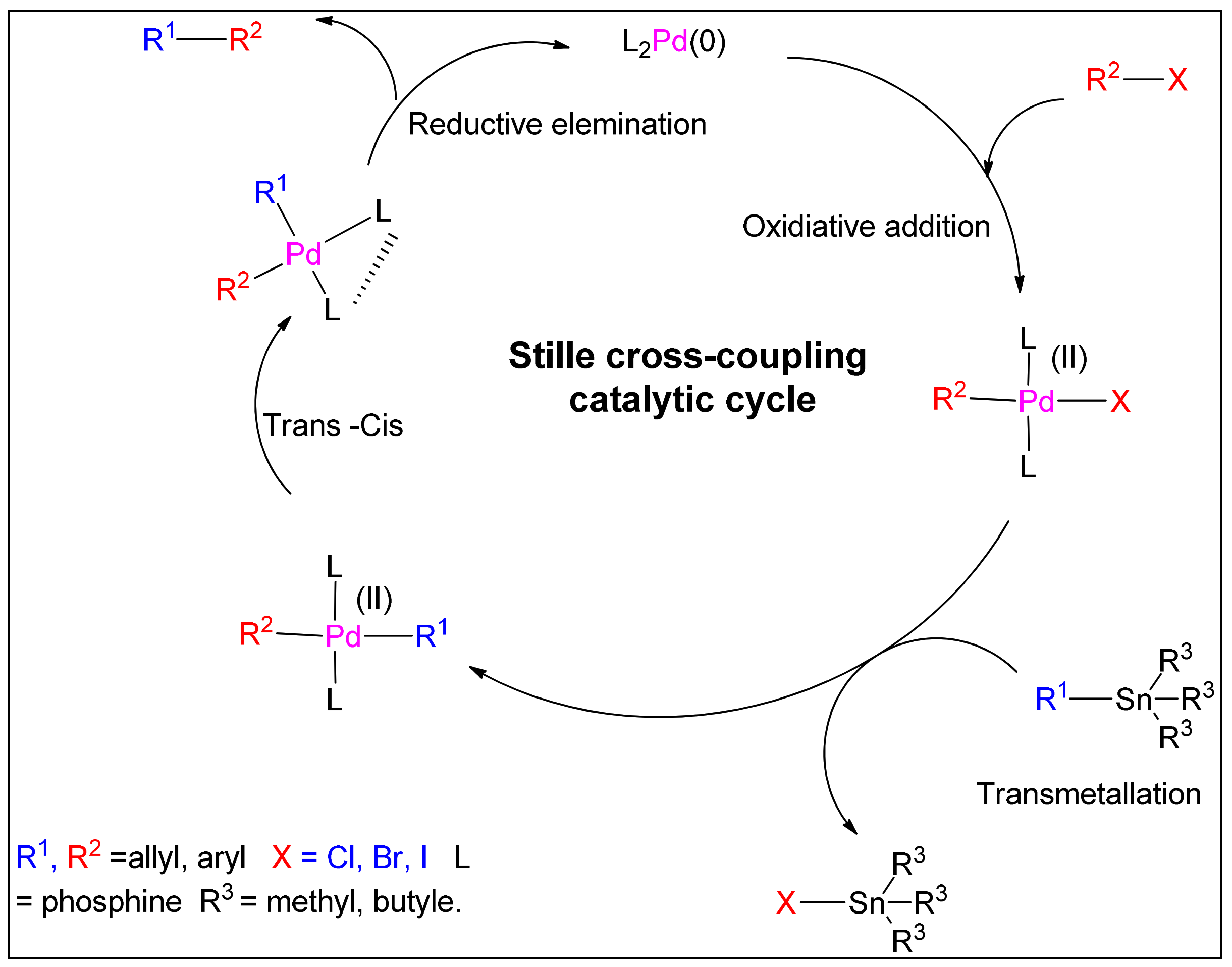
7.1. Stille Coupling Reaction
7.2. Suzuki Coupling Reaction
7.3. Sonogashira Coupling Reaction
8. The Use of Fused Rings as Electron Donor and Acceptor Units in Conjugated Polymers
8.1. Fluorene as Donor Unit in Conjugated Polymers
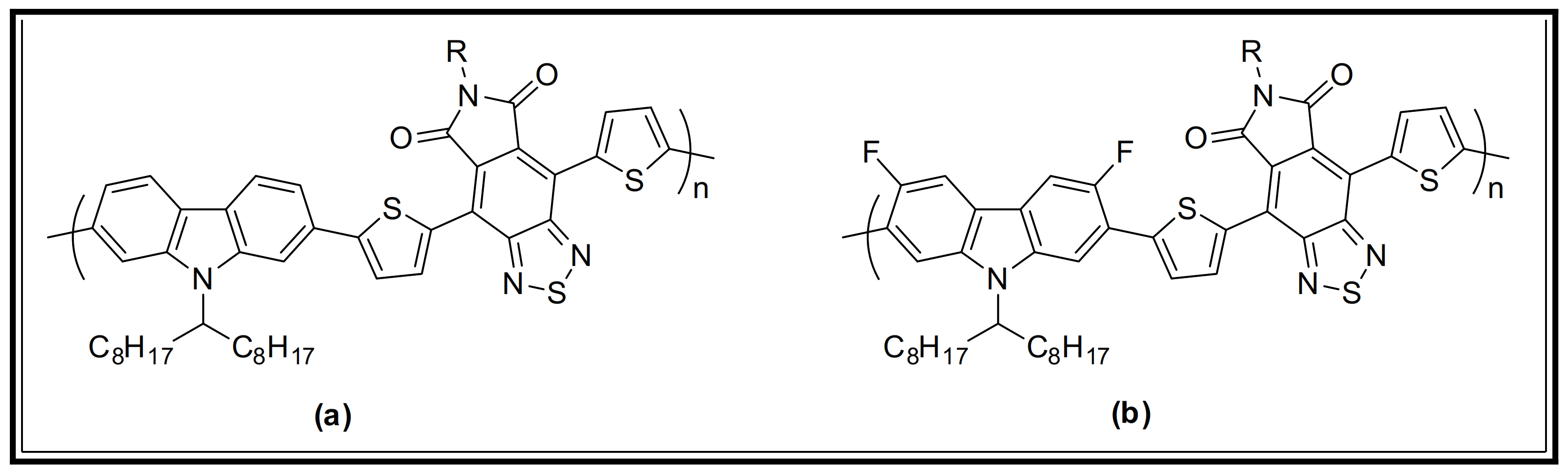
8.2. Carbazole as Donor Unit in Conjugated Polymers
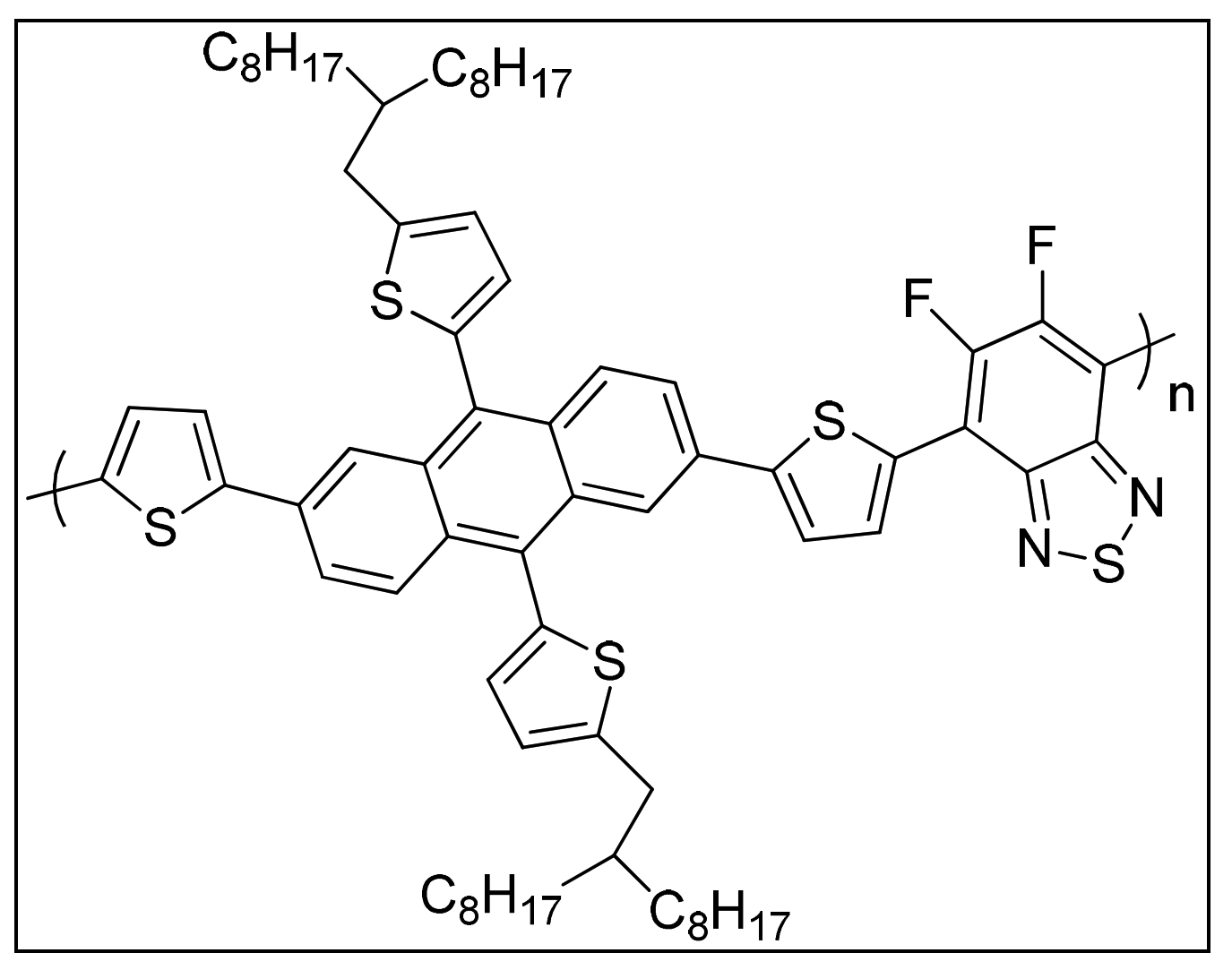
8.3. Anthracene-Based Conjugated Polymers for Application in Solar Cells
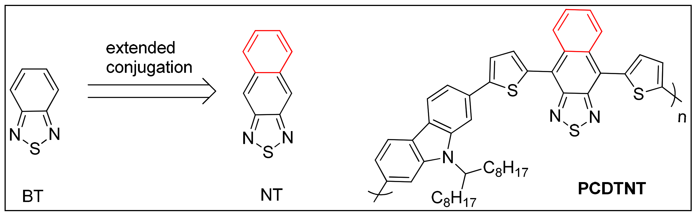
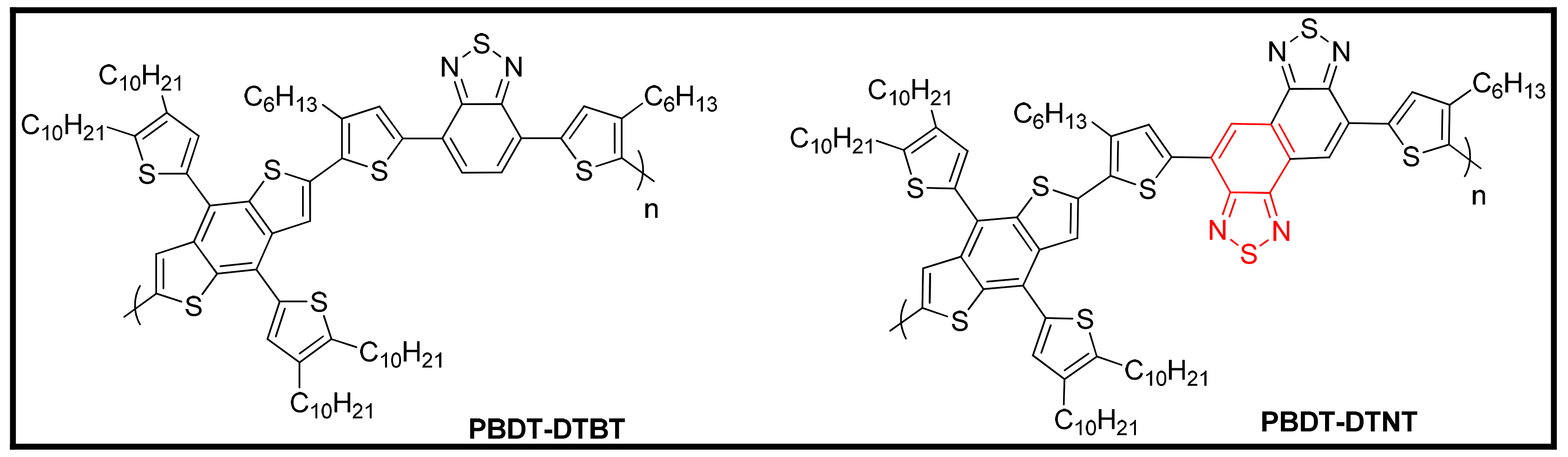
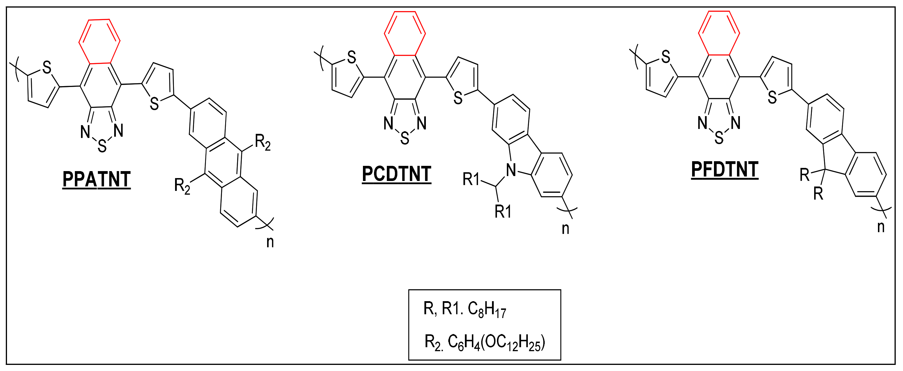
8.4. Benzothiadiazole and Naphthothiadiazole Units in Conjugated Polymers
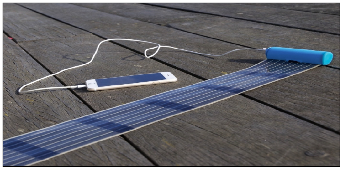
9. Commercial Success of Organic Solar Cells
10. Summary and Perspectives
Author Contributions
Funding
Institutional Review Board Statement
Data Availability Statement
Acknowledgments
Conflicts of Interest
References
- Heeger, A.J. Semiconducting and metallic polymers: The fourth generation of polymeric materials (Nobel lecture). Angew. Chem. Int. Ed. 2001, 40, 2591–2611. [Google Scholar] [CrossRef]
- Bloor, D.; Movaghar, B. Conducting polymers. Solid-State Electron Devices IEE Proc. I 1983, 130, 225–232. [Google Scholar] [CrossRef]
- Chiang, C.K.; Gau, S.C.; Fincher, C.R., Jr.; Park, Y.W.; MacDiarmid, A.G.; Heeger, A.J. Polyacetylene,(CH)x: n-type and p-type doping and compensation. Appl. Phys. Lett. 1978, 33, 18–20. [Google Scholar] [CrossRef]
- Wegner, G. Polymers with Metal-Like Conductivity—A Review of their Synthesis, Structure and Properties. Angew. Chem. Int. Ed. Engl. 1981, 20, 361–381. [Google Scholar] [CrossRef]
- Heeger, A.J. Semiconducting polymers: The third generation. Chem. Soc. Rev. 2010, 39, 2354–2371. [Google Scholar] [CrossRef] [PubMed]
- Gurunathan, K.; Murugan, A.V.; Marimuthu, R.; Mulik, U.P.; Amalnerkar, D.P. Electrochemically synthesised conducting polymeric materials for applications towards technology in electronics, optoelectronics and energy storage devices. Mater. Chem. Phys. 1999, 61, 173–191. [Google Scholar] [CrossRef]
- Pron, A.; Rannou, P. Processible conjugated polymers: From organic semiconductors to organic metals and superconductors. Prog. Polym. Sci. 2002, 27, 135–190. [Google Scholar] [CrossRef]
- Ito, T.; Shirakawa, H.; Ikeda, S. Simultaneous polymerization and formation of polyacetylene film on the surface of concentrated soluble Ziegler-type catalyst solution. J. Polym. Sci. Polym. Chem. Ed. 1974, 12, 11–20. [Google Scholar] [CrossRef]
- MacDiarmid, A.G. “Synthetic metals”: A novel role for organic polymers (Nobel lecture). Angew. Chem. Int. Ed. 2001, 40, 2581–2590. [Google Scholar] [CrossRef]
- Salaneck, W.R.; Friend, R.H.; Brédas, J.L. Electronic structure of conjugated polymers: Consequences of electron–lattice coupling. Phys. Rep. 1999, 319, 231–251. [Google Scholar] [CrossRef]
- Nicolini, C. Nanobiotechnology and Nanobiosciences; Pan Stanford Publishing: New York, NY, USA, 2009; Volume 1. [Google Scholar]
- Salaneck, W.; Sato, N.; Lazzaroni, R.; Lögdlund, M. Electronic and chemical structure of conjugated polymer ‘surfaces’. Vacuum 1990, 41, 1648–1650. [Google Scholar] [CrossRef]
- Chandrasekhar, P. Conducting Polymers, Fundamentals and Applications: A Practical Approach; Springer Science & Business Media: Berlin/Heidelberg, Germany, 2013. [Google Scholar]
- Shirakawa, H. The discovery of polyacetylene film: The dawning of an era of conducting polymers (Nobel lecture). Angew. Chem. Int. Ed. 2001, 40, 2574–2580. [Google Scholar] [CrossRef]
- Cremer, J.; Bäuerle, P.; Wienk, M.M.; Janssen, R.A. High open-circuit voltage poly(ethynylene bithienylene): Fullerene solar cells. Chem. Mater. 2006, 18, 5832–5834. [Google Scholar] [CrossRef]
- Bar-Lev, A. Semiconductors and Electronic Devices; Prentice-Hall, Inc.: Hoboken, NJ, USA, 1993. [Google Scholar]
- Pople, J.A.; Gordon, M. Molecular orbital theory of the electronic structure of organic compounds. I. Substituent effects and dipole moments. J. Am. Chem. Soc. 1967, 89, 4253–4261. [Google Scholar] [CrossRef]
- Dang, D.; Chen, W.; Yang, R.; Zhu, W.; Mammo, W.; Wang, E. Fluorine substitution enhanced photovoltaic performance of a D–A 1–D–A 2 copolymer. Chem. Commun. 2013, 49, 9335–9337. [Google Scholar] [CrossRef] [Green Version]
- Schwartz, B.J. Conjugated polymers as molecular materials: How chain conformation and film morphology influence energy transfer and interchain interactions. Annu. Rev. Phys. Chem. 2003, 54, 141–172. [Google Scholar] [CrossRef] [Green Version]
- Halls, J.J.M.; Cornil, J.; Dos Santos, D.A.; Silbey, R.; Hwang, D.-H.; Holmes, A.B.; Brédas, J.L.; Friend, R.H. Charge-and energy-transfer processes at polymer/polymer interfaces: A joint experimental and theoretical study. Phys. Rev. B 1999, 60, 5721. [Google Scholar] [CrossRef] [Green Version]
- Mark, J. Physical Properties of Polymers Handbook; Springer: New York, NY, USA, 2007; Chapter 16; p. 289. [Google Scholar]
- Tsukamoto, J.; Takahashi, A. Synthesis and electrical properties of polyacetylene yielding conductivity of 105 S/cm. Synth. Met. 1991, 41, 7–12. [Google Scholar] [CrossRef]
- Andersson, M.R.; Väkiparta, K.; Reghu, M.; Cao, Y.; Moses, D. Conductivity of oriented polyacetylene doped by alkali metals: Time, temperature, and pressure dependence. Phys. Rev. B 1993, 47, 9238. [Google Scholar] [CrossRef]
- Mühlbacher, D.; Scharber, M.; Morana, M.; Zhu, Z.; Waller, D.; Gaudiana, R.; Brabec, C.J. High photovoltaic performance of a low-bandgap polymer. Adv. Mater. 2006, 18, 2884–2889. [Google Scholar] [CrossRef]
- Osaka, I. Semiconducting polymers based on electron-deficient π-building units. Polym. J. 2015, 47, 18–25. [Google Scholar] [CrossRef]
- Xu, T.; Yu, L. How to design low bandgap polymers for highly efficient organic solar cells. Mater. Today 2014, 17, 11–15. [Google Scholar] [CrossRef]
- Kim, J.; Yun, M.H.; Kim, G.H.; Lee, J.; Lee, S.M.; Ko, S.J.; Kim, Y.; Dutta, G.K.; Moon, M.; Park, S.Y.; et al. Synthesis of PCDTBT-based fluorinated polymers for high open-circuit voltage in organic photovoltaics: Towards an understanding of relationships between polymer energy levels engineering and ideal morphology control. ACS Appl. Mater. Interfaces 2014, 6, 7523–7534. [Google Scholar] [CrossRef] [PubMed]
- Zhou, H.; Yang, L.; You, W. You, Rational design of high performance conjugated polymers for organic solar cells. Macromolecules 2012, 45, 607–632. [Google Scholar] [CrossRef] [Green Version]
- Cheng, Y.-J.; Yang, S.-H.; Hsu, C.-S. Synthesis of conjugated polymers for organic solar cell applications. Chem. Rev. 2009, 109, 5868–5923. [Google Scholar] [CrossRef]
- Homyak, P.; Liu, Y.; Liu, F.; Russel, T.P.; Coughlin, E.B. Systematic variation of fluorinated diketopyrrolopyrrole low bandgap conjugated polymers: Synthesis by direct arylation polymerization and characterization and performance in organic photovoltaics and organic field-effect transistors. Macromolecules 2015, 48, 6978–6986. [Google Scholar] [CrossRef]
- Zhou, E.; Hashimoto, K.; Tajima, K. Low band gap polymers for photovoltaic device with photocurrent response wavelengths over 1000 nm. Polymer 2013, 54, 6501–6509. [Google Scholar] [CrossRef] [Green Version]
- Hoppe, H.; Sariciftci, N.S. Organic solar cells: An overview. J. Mater. Res. 2004, 19, 1924–1945. [Google Scholar] [CrossRef] [Green Version]
- Lin, T.-C.; Subramani, T.; Syu, H.-J.; Hsueh, C.-C.; Liu, C.-T.; Uma, K.; Lin, C.-F. Morphology dependence of silicon nanostructure/organic polymer solar cell. In Proceedings of the 2013 IEEE 39th Photovoltaic Specialists Conference (PVSC), Tampa, FL, USA, 16–21 June 2013. [Google Scholar]
- Günes, S.; Neugebauer, H.; Sariciftci, N.S. Conjugated polymer-based organic solar cells. Chem. Rev. 2007, 107, 1324–1338. [Google Scholar] [CrossRef]
- Spanggaard, H.; Krebs, F.C. A brief history of the development of organic and polymeric photovoltaics. Sol. Energy Mater. Sol. Cells 2004, 83, 125–146. [Google Scholar] [CrossRef]
- Saxena, V.; Malhotra, B. Prospects of conducting polymers in molecular electronics. Curr. Appl. Phys. 2003, 3, 293–305. [Google Scholar] [CrossRef]
- Friend, R.H.; Gymer, R.W.; Holmes, A.B.; Burroughes, J.H.; Marks, R.N.; Taliani, C.; Bradley, D.D.C.; Dos Santos, D.A.; Brédas, J.L.; Lögdlund, M.; et al. Electroluminescence in conjugated polymers. Nature 1999, 397, 121–128. [Google Scholar] [CrossRef]
- Jou, J.-H.; Kumar, S.; Agrawal, A.; Li, T.-H.; Sahoo, S. Approaches for fabricating high efficiency organic light emitting diodes. J. Mater. Chem. C 2015, 3, 2974–3002. [Google Scholar] [CrossRef]
- Kulkarni, A.P.; Tonzola, C.J.; Babel, A.; Jenekhe, S.A. Electron transport materials for organic light-emitting diodes. Chem. Mater. 2004, 16, 4556–4573. [Google Scholar] [CrossRef]
- Geffroy, B.; Le Roy, P.; Prat, C. Organic light-emitting diode (OLED) technology: Materials, devices and display technologies. Polym. Int. 2006, 55, 572–582. [Google Scholar] [CrossRef]
- Kappaun, S.; Slugovc, C.; List, E.J.W. Phosphorescent organic light-emitting devices: Working principle and iridium based emitter materials. Int. J. Mol. Sci. 2008, 9, 1527–1547. [Google Scholar] [CrossRef] [Green Version]
- Horowitz, G. Organic field-effect transistors. Adv. Mater. 1998, 10, 365–377. [Google Scholar] [CrossRef]
- Di, C.-A.; Yu, G.; Liu, Y.; Zhu, D. High-performance organic field-effect transistors: Molecular design, device fabrication, and physical properties. J. Phys. Chem. B 2007, 111, 14083–14096. [Google Scholar] [CrossRef]
- Bao, Z.; Locklin, J. Organic Field-Effect Transistors, 1st ed.; CRC Press: New York, NY, USA, 2007. [Google Scholar]
- Krebs, F.C. Polymeric Solar Cells: Materials, Design, Manufacture; DEStech Publications, Inc.: Lancaster, PA, USA, 2010. [Google Scholar]
- Benanti, T.L.; Venkataraman, D. Organic solar cells: An overview focusing on active layer morphology. Photosynth. Res. 2006, 87, 73–81. [Google Scholar] [CrossRef]
- Rikken, G.L.J.A.; Braun, D.; Staring, E.G.J.; Demandt, R.J.C.E. Schottky effect at a metal-polymer interface. Appl. Phys. Lett. 1994, 65, 219–221. [Google Scholar] [CrossRef]
- Uddin, M.A.; Chan, H.; Rahman, B. Structural improvement of organic photovoltaic cell (OPVC) towards higher efficiency. Rev. Adv. Mater. Sci. 2010, 26, 58–66. [Google Scholar]
- Tang, C.W. Two-Layer organic photovoltaic cell. Appl. Phys. Lett. 1986, 48, 183–185. [Google Scholar] [CrossRef]
- Yeh, N.; Yeh, P. Organic solar cells: Their developments and potentials. Renew. Sustain. Energy Rev. 2013, 21, 421–431. [Google Scholar] [CrossRef]
- Peumans, P.; Yakimov, A.; Forrestb, S.R. Small molecular weight organic thin-film photodetectors and solar cells. J. Appl. Phys. 2003, 93, 3693–3723. [Google Scholar] [CrossRef]
- Gommans, H.H.P.; Cheyns, D.; Aernouts, T.; Girotto, C.; Poortmans, J.; Heremans, P. Electro-Optical Study of Subphthalocyanine in a Bilayer Organic Solar Cell. Adv. Funct. Mater. 2007, 17, 2653–2658. [Google Scholar] [CrossRef]
- Pettersson, L.A.A.; Roman, L.S.; Inganäs, O. Modeling photocurrent action spectra of photovoltaic devices based on organic thin films. J. Appl. Phys. 1999, 86, 487. [Google Scholar] [CrossRef]
- Forrest, S.R. The limits to organic photovoltaic cell efficiency. MRS Bull. 2005, 30, 28–32. [Google Scholar] [CrossRef]
- Yu, G.; Gao, J.; Hummelen, J.C.; Wudl, F.; Heeger, A.J. Polymer photovoltaic cells: Enhanced efficiencies via a network of internal donor-acceptor heterojunctions. Sci.-AAAS-Wkly. Pap. Ed. 1995, 270, 1789–1790. [Google Scholar] [CrossRef] [Green Version]
- Yang, Y.; Chen, W.; Dou, L.; Chang, W.-H.; Duan, H.-S.; Bob, B.; Li, G. High-performance multiple-donor bulk heterojunction solar cells. Nat. Photonics 2015, 9, 190–198. [Google Scholar] [CrossRef]
- Bisquert, J.; Garcia-Belmonte, G. On voltage, photovoltage, and photocurrent in bulk heterojunction organic solar cells. J. Phys. Chem. Lett. 2011, 2, 1950–1964. [Google Scholar] [CrossRef]
- Garcia-Belmonte, G.; Munar, A.; Barea, E.M.; Bisquert, J.; Ugarte, I.; Pacios, R. Charge carrier mobility and lifetime of organic bulk heterojunctions analyzed by impedance spectroscopy. Org. Electron. 2008, 9, 847–851. [Google Scholar] [CrossRef]
- van Duren, J.K.; Yang, X.; Loos, J.; Bulle-Lieuwma, C.W.; Sieval, A.B.; Hummelen, J.C.; Janssen, R.A. Relating the morphology of poly (p-phenylene vinylene)/methanofullerene blends to solar-cell performance. Adv. Funct. Mater. 2004, 14, 425–434. [Google Scholar] [CrossRef]
- Coakley, K.M.; McGehee, M.D. Conjugated polymer photovoltaic cells. Chem. Mater. 2004, 16, 4533–4542. [Google Scholar] [CrossRef]
- Seok, J.; Shin, T.J.; Park, S.; Cho, C.; Lee, J.Y.; Du Ryu, Y.; Kim, M.H.; Kim, K. Efficient Organic Photovoltaics Utilizing Nanoscale Heterojunctions in Sequentially Deposited Polymer/fullerene Bilayer. Sci. Rep. 2015, 5, 8373. [Google Scholar] [CrossRef] [Green Version]
- Sprau, C.; Buss, F.; Wagner, M.; Landerer, D.; Koppitz, M.; Schulz, A.; Bahro, D.; Schabel, W.; Scharfer, P.; Colsmann, A. Highly efficient polymer solar cells cast from non-halogenated xylene/anisaldehyde solution. Energy Environ. Sci. 2015, 8, 2744–2752. [Google Scholar] [CrossRef] [Green Version]
- He, K.; Kumar, P.; Yuan, Y.; Li, Y. Wide bandgap polymer donors for high efficiency non-fullerene acceptor based organic solar cells. Mater. Adv. 2021, 2, 115–145. [Google Scholar] [CrossRef]
- Han, Y.W.; Jeon, S.J.; Lee, H.S.; Park, H.; Kim, K.S.; Lee, H.; Moon, D.K. Evaporation-free nonfullerene flexible organic solar cell modules manufactured by an all-solution process. Adv. Energy Mater. 2019, 9, 1902065. [Google Scholar] [CrossRef]
- Zhao, W.; Li, S.; Yao, H.; Zhang, S.; Zhang, Y.; Yang, B.; Hou, J. Molecular optimization enables over 13% efficiency in organic solar cells. J. Am. Chem. Soc. 2017, 139, 7148–7151. [Google Scholar] [CrossRef]
- Jeon, S.J.; Han, Y.W.; Moon, D.K. 13.9%-efficiency and eco-friendly nonfullerene polymer solar cells obtained by balancing molecular weight and solubility in chlorinated thiophene-based polymer backbones. Small 2019, 15, 1902598. [Google Scholar] [CrossRef]
- Cui, Y.; Yao, H.; Hong, L.; Zhang, T.; Tang, Y.; Lin, B.; Xian, K.; Gao, B.; An, C.; Bi, P.; et al. Organic photovoltaic cell with 17% efficiency and superior processability. Natl. Sci. Rev. 2020, 7, 1239–1246. [Google Scholar] [CrossRef]
- Cui, Y.; Xu, Y.; Yao, H.; Bi, P.; Hong, L.; Zhang, J.; Zu, Y.; Zhang, T.; Qin, J.; Ren, J.; et al. Single-junction organic photovoltaic cell with 19% efficiency. Adv. Mater. 2021, 33, 2102420. [Google Scholar] [CrossRef] [PubMed]
- Gregg, B.A. Excitonic solar cells. J. Phys. Chem. B 2003, 107, 4688–4698. [Google Scholar] [CrossRef]
- Clarke, T.M.; Durrant, J.R. Charge photogeneration in organic solar cells. Chem. Rev. 2010, 110, 6736–6767. [Google Scholar] [CrossRef] [PubMed]
- Bakulin, A.A.; Rao, A.; Pavelyev, V.G.; van Loosdrecht, P.H.M.; Pshenichnikov, M.S.; Niedzialek, D.; Cornil, J.; Beljonne, D.; Friend, R.H. The role of driving energy and delocalized states for charge separation in organic semiconductors. Science 2012, 335, 1340–1344. [Google Scholar] [CrossRef] [PubMed] [Green Version]
- Kim, H.; Gilmore, A.C.; Pique, A.; Horwitz, J.S.; Mattoussi, H.; Murata, H.; Kafafi, Z.H.; Chrisey, D.B. Electrical, optical, and structural properties of indium–tin–oxide thin films for organic light-emitting devices. J. Appl. Phys. 1999, 86, 6451–6461. [Google Scholar] [CrossRef]
- Haruk, A.M.; Mativetsky, J.M. Supramolecular Approaches to Nanoscale Morphological Control in Organic Solar Cells. Int. J. Mol. Sci. 2015, 16, 13381–13406. [Google Scholar] [CrossRef] [Green Version]
- Hoppe, H.; Sariciftci, N.S. Morphology of polymer/fullerene bulk heterojunction solar cells. J. Mater. Chem. 2006, 16, 45–61. [Google Scholar] [CrossRef]
- Vivek, K.; Agrawal, G. Organic Solar Cells: Principles, Mechanism and recent dvelopments. Hypothesis 2014, 17, 18. [Google Scholar]
- Chochos, C.L.; Choulis, S.A. How the structural deviations on the backbone of conjugated polymers influence their optoelectronic properties and photovoltaic performance. Prog. Polym. Sci. 2011, 36, 1326–1414. [Google Scholar] [CrossRef]
- Chen, W.; Nikiforov, M.P.; Darling, S.B. Darling, Morphology characterization in organic and hybrid solar cells. Energy Environ. Sci. 2012, 5, 8045–8074. [Google Scholar] [CrossRef]
- Mazzio, K.A.; Luscombe, C.K. The future of organic photovoltaics. Chem. Soc. Rev. 2015, 44, 78–90. [Google Scholar] [CrossRef]
- Hertel, D.; Bässler, H.; Scherf, U.; Hörhold, H.H. Charge carrier transport in conjugated polymers. J. Chem. Phys. 1999, 110, 9214–9222. [Google Scholar] [CrossRef]
- Bian, L.; Zhu, E.; Tang, J.; Tang, W.; Zhang, F. Recent progress in the design of narrow bandgap conjugated polymers for high-efficiency organic solar cells. Prog. Polym. Sci. 2012, 37, 1292–1331. [Google Scholar] [CrossRef]
- Qi, B.; Wang, J. Fill factor in organic solar cells. Phys. Chem. Chem. Phys. 2013, 15, 8972–8982. [Google Scholar] [CrossRef]
- Zhou, N.; Lin, H.; Lou, S.J.; Yu, X.; Guo, P.; Manley, E.F.; Loser, S.; Hartnett, P.; Huang, H.; Wasielewski, M.R.; et al. Morphology-Performance Relationships in High-Efficiency All-Polymer Solar Cells. Adv. Energy Mater. 2014, 4, 1300785. [Google Scholar] [CrossRef]
- Gupta, D.; Mukhopadhyay, S.; Narayan, K. Fill factor in organic solar cells. Sol. Energy Mater. Sol. Cells 2010, 94, 1309–1313. [Google Scholar] [CrossRef]
- Armin, A.; Velusamy, M.; Wolfer, P.; Zhang, Y.; Burn, P.L.; Meredith, P.; Pivrikas, A. Quantum efficiency of organic solar cells: Electro-optical cavity considerations. ACS Photonics 2014, 1, 173–181. [Google Scholar] [CrossRef]
- Zhang, S.; Ye, L.; Zhao, W.; Liu, D.; Yao, H.; Hou, J. Side chain selection for designing highly efficient photovoltaic polymers with 2D-conjugated structure. Macromolecules 2014, 47, 4653–4659. [Google Scholar] [CrossRef]
- Kim, J.H.; Park, J.B.; Jung, I.H.; Grimsdale, A.C.; Yoon, S.C.; Yang, H.; Hwang, D.H. Well-controlled thieno[3,4-c] pyrrole-4,6-(5H)-dione based conjugated polymers for high performance organic photovoltaic cells with the power conversion efficiency exceeding 9%. Energy Environ. Sci. 2015, 8, 2352–2356. [Google Scholar] [CrossRef]
- Li, Y.; Xu, B.; Li, H.; Cheng, W.; Xue, L.; Chen, F.; Lu, H.; Tian, W. Molecular Engineering of Copolymers with Donor−Acceptor Structure for Bulk Heterojunction Photovoltaic Cells Toward High Photovoltaic Performance. J. Phys. Chem. C 2011, 115, 2386–2397. [Google Scholar] [CrossRef]
- Kroon, R.; Lenes, M.; Hummelen, J.C.; Blom, P.W.M.; de Boer, B. Small bandgap polymers for organic solar cells (polymer material development in the last 5 years). Polym. Rev. 2008, 48, 531–582. [Google Scholar] [CrossRef]
- Chao, C.Y.; Chao, C.H.; Chen, L.P.; Hung, Y.C.; Lin, S.T.; Su, W.F.; Lin, C.F. Band structure engineering for low band gap polymers containing thienopyrazine. J. Mater. Chem. 2012, 22, 7331–7341. [Google Scholar] [CrossRef]
- Bakhshi, A.; Kaur, A.; Arora, V. Molecular engineering of novel low band gap conducting polymers. Indian J. Chem.-Part A Inorg. Theor. Anal. 2012, 51, 57. [Google Scholar]
- Chen, L.-M.; Xu, Z.; Hong, Z.; Yang, Y. Interface investigation and engineering–achieving high performance polymer photovoltaic devices. J. Mater. Chem. 2010, 20, 2575–2598. [Google Scholar] [CrossRef]
- Scharber, M.; Sariciftci, N. Efficiency of bulk-heterojunction organic solar cells. Prog. Polym. Sci. 2013, 38, 1929–1940. [Google Scholar] [CrossRef] [Green Version]
- Roncali, J. Molecular engineering of the band gap of π-conjugated systems: Facing technological applications. Macromol. Rapid Commun. 2007, 28, 1761–1775. [Google Scholar] [CrossRef]
- Tadesse, T. Introduction to The Application of Organic Polymers for Photovoltaic Devices Organic Electronics Approach: Critical Review. Rev. Knowl. Econ. 2015, 15, 65–79. [Google Scholar] [CrossRef] [Green Version]
- Brabec, C.J.; Gowrisanker, S.; Halls, J.J.; Laird, D.; Jia, S.; Williams, S.P. Polymer–fullerene bulk-heterojunction solar cells. Adv. Mater. 2010, 22, 3839–3856. [Google Scholar] [CrossRef]
- Johansson Seechurn, C.C.C.; Kitching, M.O.; Colacot, T.J.; Snieckus, V. Palladium-Catalyzed Cross-Coupling: A Historical Contextual Perspective to the 2010 Nobel Prize. Angew. Chem. Int. Ed. 2012, 51, 5062–5085. [Google Scholar] [CrossRef]
- Miyaura, N.; Suzuki, A. Palladium-catalyzed cross-coupling reactions of organoboron compounds. Chem. Rev. 1995, 95, 2457–2483. [Google Scholar] [CrossRef] [Green Version]
- Espinet, P.; Echavarren, A.M. The mechanisms of the Stille reaction. Angew. Chem. Int. Ed. 2004, 43, 4704–4734. [Google Scholar]
- Miyaura, N.; Yamada, K.; Suzuki, A. A new stereospecific cross-coupling by the palladium-catalyzed reaction of 1-alkenylboranes with 1-alkenyl or 1-alkynyl halides. Tetrahedron Lett. 1979, 20, 3437–3440. [Google Scholar] [CrossRef] [Green Version]
- Gujral, S.S.; Khatri, S.; Riyal, P.; Gahlot, V. Suzuki Cross Coupling Reaction-A Review. Indo Glob. J. Pharm. Sci 2012, 2, 351–367. [Google Scholar] [CrossRef]
- Kotha, S.; Lahiri, K.; Kashinath, D. Recent applications of the Suzuki–Miyaura cross-coupling reaction in organic synthesis. Tetrahedron 2002, 58, 9633–9695. [Google Scholar] [CrossRef]
- Amatore, C.; Jutand, A.; Le Duc, G. Kinetic Data for the Transmetalation/Reductive Elimination in Palladium-Catalyzed Suzuki–Miyaura Reactions: Unexpected Triple Role of Hydroxide Ions Used as Base. Chem.-A Eur. J. 2011, 17, 2492–2503. [Google Scholar] [CrossRef]
- Matos, K.; Soderquist, J.A. Soderquist, Alkylboranes in the Suzuki-Miyaura coupling: Stereochemical and mechanistic studies. J. Org. Chem. 1998, 63, 461–470. [Google Scholar] [CrossRef]
- Chinchilla, R.; Nájera, C. The Sonogashira reaction: A booming methodology in synthetic organic chemistry. Chem. Rev. 2007, 107, 874–922. [Google Scholar] [CrossRef]
- Fukuyama, T.; Shinmen, M.; Nishitani, S.; Sato, M.; Ryu, I. A copper-free Sonogashira coupling reaction in ionic liquids and its application to a microflow system for efficient catalyst recycling. Org. Lett. 2002, 4, 1691–1694. [Google Scholar] [CrossRef]
- Muthukumar, M.; Ober, C.; Thomas, E. Competing interactions and levels of ordering in self-organizing polymeric materials. Science 1997, 277, 1225–1232. [Google Scholar] [CrossRef] [Green Version]
- Wallace, J.U.; Chen, S. Fluorene-Based Conjugated Oligomers for Organic Photonics and Electronics, in Polyfluorenes; Springer: Berlin/Heidelberg, Germany, 2008; pp. 145–186. [Google Scholar]
- Wang, E.; Wang, L.; Lan, L.; Luo, C.; Zhuang, W.; Peng, J.; Cao, Y. High-performance polymer heterojunction solar cells of a polysilafluorene derivative. Appl. Phys. Lett. 2008, 92, 33307. [Google Scholar] [CrossRef]
- Watters, D.C.; Yi, H.; Pearson, A.J.; Kingsley, J.; Iraqi, A.; Lidzey, D. Fluorene-Based Co-polymer with High Hole Mobility and Device Performance in Bulk Heterojunction Organic Solar Cells. Macromol. Rapid Commun. 2013, 34, 1157–1162. [Google Scholar] [CrossRef] [PubMed]
- Murad, A.R.; Iraqi, A.; Aziz, S.B.; Abdullah, S.N.; Abdulwahid, R.T.; Hussen, S.A. Optical, Electrochemical, Thermal, and Structural Properties of Synthesized Fluorene/Dibenzosilole-Benzothiadiazole Dicarboxylic Imide Alternating Organic Copolymers for Photovoltaic Applications. Coatings 2020, 10, 1147. [Google Scholar] [CrossRef]
- Zhu, E.; Bian, L.; Hai, J.; Tang, W.; Zhang, W.T.A.F. Towards High-Efficiency Organic Solar Cells: Polymers and Devices Development; Intech Open Access Publisher: London, UK, 2011. [Google Scholar]
- Brabec, C.; Scherf, U.; Dyakonov, V. Organic Photovoltaics: Materials, Device Physics, and Manufacturing Technologies; John Wiley & Sons: Hoboken, NJ, USA, 2011. [Google Scholar]
- Zhang, Z.-G.; Liu, Y.-L.; Yang, Y.; Hou, K.; Peng, B.; Zhao, G.; Zhang, M.; Guo, X.; Kang, E.-T.; Li, Y. Alternating copolymers of carbazole and triphenylamine with conjugated side chain attaching acceptor groups: Synthesis and photovoltaic application. Macromolecules 2010, 43, 9376–9383. [Google Scholar] [CrossRef]
- Chu, T.Y.; Alem, S.; Tsang, S.W.; Tse, S.C.; Wakim, S.; Lu, J.; Dennler, G.; Waller, D.; Gaudiana, R.; Tao, Y. Morphology control in polycarbazole based bulk heterojunction solar cells and its impact on device performance. Appl. Phys. Lett. 2011, 98, 253301. [Google Scholar] [CrossRef]
- Murad, A.R.; Iraqi, A.; Aziz, S.B.; Hi, H.; Abdullah, S.N.; Brza, M.A.; Abdulwahid, R.T. Influence of fluorine substitution on the optical, thermal, electrochemical and structural properties of carbazole-benzothiadiazole dicarboxylic imide alternate copolymers. Polymers 2020, 12, 2910. [Google Scholar] [CrossRef]
- Al-Azzawi, A.G.; Aziz, S.B.; Iraqi, A.; Murad, A.R.; Abdulwahid, R.T.; Alshehri, S.M.; Ahamad, T. IImpact of ethynylene linkers on the optical and electrochemical properties of benzothiadiazole based alternate conjugated polymers. Arab. J. Chem. 2021, 14, 103320. [Google Scholar] [CrossRef]
- Cui, W.; Wu, Y.; Tian, H.; Geng, Y.; Wang, F. The first soluble conjugated poly (2,6-anthrylene): Synthesis and properties. Chem. Commun. 2008, 8, 1017–1019. [Google Scholar] [CrossRef]
- Xu, J.; Fang, Y.; Ren, P.; Zhang, H.; Guo, E.; Yang, W. Synthesis and Electrooptic Properties of Poly (2,6-anthracenevinylene)s. Macromol. Rapid Commun. 2008, 29, 1415–1420. [Google Scholar] [CrossRef]
- Usluer, Ö.; Boudiba, S.; Egbe, D.A.M.; Hirsch, L.; Abbas, M. Control of carrier mobilities for performance enhancement of anthracene-based polymer solar cells. RSC Adv. 2015, 5, 50668–50672. [Google Scholar] [CrossRef] [Green Version]
- Egbe, D.A.; Turk, S.; Rathgeber, S.; Kuhnlenz, F.; Jadhav, R.; Wild, A.; Birckner, E.; Adam, G.; Pivrikas, A.; Cimrova, V.; et al. Anthracene based conjugated polymers: Correlation between π−π-stacking ability, photophysical properties, charge carrier mobility, and photovoltaic performance. Macromolecules 2010, 43, 1261–1269. [Google Scholar] [CrossRef]
- Jung, J.W.; Liu, F.; Russell, T.P.; Jo, W.H. Anthracene-Based Medium Bandgap Conjugated Polymers for High Performance Polymer Solar Cells Exceeding 8% PCE Without Additive and Annealing Process. Adv. Energy Mater. 2015, 5, 1500065. [Google Scholar] [CrossRef]
- Murad, A.R.; Iraqi, A.; Aziz, S.B.; Almeataq, M.S.; Abdullah, S.N.; Brza, M.A. Characteristics of low band gap copolymers containing anthracene-benzothiadiazole dicarboxylic imide: Synthesis, optical, electrochemical, thermal and structural studies. Polymers 2021, 13, 62. [Google Scholar] [CrossRef]
- Zhou, P.; Zhang, Z.-G.; Li, Y.; Chen, X.; Qin, J. Thiophene-Fused Benzothiadiazole: A Strong Electron-Acceptor Unit to Build D–A Copolymer for Highly Efficient Polymer Solar Cells. Chem. Mater. 2014, 26, 3495–3501. [Google Scholar] [CrossRef]
- Osaka, I.; Shimawaki, M.; Mori, H.; Doi, I.; Miyazaki, E.; Koganezawa, T.; Takimiya, K. Synthesis, characterization, and transistor and solar cell applications of a naphthobisthiadiazole-based semiconducting polymer. J. Am. Chem. Soc. 2012, 134, 3498–3507. [Google Scholar] [CrossRef]
- Kim, J.; Yun, M.H.; Kim, G.H.; Kim, J.Y.; Yang, C. Replacing 2,1,3-benzothiadiazole with 2,1,3-naphthothiadiazole in PCDTBT: Towards a low bandgap polymer with deep HOMO energy level. Polym. Chem. 2012, 3, 3276–3281. [Google Scholar] [CrossRef]
- Wang, M.; Hu, X.; Liu, P.; Li, W.; Gong, X.; Huang, F.; Cao, Y. Donor–acceptor conjugated polymer based on naphtho[1,2-c:5,6-c]bis[1,2,5]thiadiazole for high-performance polymer solar cells. J. Am. Chem. Soc. 2011, 133, 9638–9641. [Google Scholar] [CrossRef]
- Al-Azzawi, A.G.S. Synthesis, Optical and Electrochemical Properties of Naphthothiadiazole-Based Donor-Acceptor Polymers and Their Photovoltaic Applications. Int. J. Electrochem. Sci. 2021, 16, 2. [Google Scholar] [CrossRef]
- Chowdhury, R.; Holmes, N.P.; Cooling, N.; Belcher, W.J.; Dastoor, P.C.; Zhou, X. Surfactant Engineering and Its Role in Determining the Performance of Nanoparticulate Organic Photovoltaic Devices. ACS Omega 2022, 7, 9212–9220. [Google Scholar] [CrossRef]
- Pandey, A.; Tyagi, V.; Selvaraj, J.A.; Rahim, N.; Tyagi, S. Recent advances in solar photovoltaic systems for emerging trends and advanced applications. Renew. Sustain. Energy Rev. 2016, 53, 859–884. [Google Scholar] [CrossRef]
- Sanseverino, E. Life-Cycle Land-Use Requir. PV Vietnam. Energ. 2021, 14, 861. [Google Scholar]
- Liu, F.; Zhou, L.; Liu, W.; Zhou, Z.; Yue, Q.; Zheng, W.; Sun, R.; Liu, W.; Xu, S.; Fan, H.; et al. Organic solar cells with 18% efficiency enabled by an alloy acceptor: A two-in-one strategy. Adv. Mater. 2021, 33, 2100830. [Google Scholar] [CrossRef] [PubMed]
- Rammal, M.; Lévêque, P.; Schlatter, G.; Leclerc, N.; Hébraud, A. Recent advances in the green processing of organic photovoltaic devices from nanoparticle dispersions. Mater. Chem. Front. 2020, 4, 2904–2931. [Google Scholar] [CrossRef]
- Chochos, C.L.; Spanos, M.; Katsouras, A.; Tatsi, E.; Drakopoulou, S.; Gregoriou, V.G.; Avgeropoulos, A. Current status, challenges and future outlook of high performance polymer semiconductors for organic photovoltaics modules. Prog. Polym. Sci. 2019, 91, 51–79. [Google Scholar] [CrossRef]
- Cooling, N.A.; Barnes, E.F.; Almyahi, F.; Feron, K.; Al-Mudhaffer, M.F.; Al-Ahmad, A.; Vaughan, B.; Andersen, T.R.; Griffith, M.J.; Hart, A.S.; et al. A low-cost mixed fullerene acceptor blend for printed electronics. J. Mater. Chem. A 2016, 4, 10274–10281. [Google Scholar] [CrossRef]
- Zhang, S.; Ye, L.; Zhang, H.; Hou, J. Green-solvent-processable organic solar cells. Mater. Today 2016, 19, 533–543. [Google Scholar] [CrossRef]
- Gärtner, S.; Christmann, M.; Sankaran, S.; Röhm, H.; Prinz, E.-M.; Penth, F.; Pütz, A.; Türeli, A.E.; Penth, B.; Baumstümmler, B.; et al. Eco-Friendly Fabrication of 4% Efficient Organic Solar Cells from Surfactant-Free P3HT: ICBA Nanoparticle Dispersions. Adv. Mater. 2014, 26, 6653–6657. [Google Scholar] [CrossRef]
- Ghazy, O.; Freisinger, B.; Lieberwith, I.; Landfester, K. Tuning the size and morphology of P3HT/PCBM composite nanoparticles: Towards optimized water-processable organic solar cells. Nanoscale 2020, 12, 22798–22807. [Google Scholar] [CrossRef]
- Riede, M.; Spoltore, D.; Leo, K. Organic solar cells—The path to commercial success. Adv. Energy Mater. 2021, 11, 2002653. [Google Scholar] [CrossRef]
- Marks, W.H. Solar Cell Efficiency Record Broken with New “Tandem” Cell. 2022. Available online: https://www.aiche.org/chenected/2012/05/solar-cell-efficiency-record-broken-new-tandem-cell?gclid=EAIaIQobChMI4rvdkY7s-gIVyZBoCR0H2QAKEAMYAiAAEgJ2k_D_BwE%20 (accessed on 20 October 2022).
- Change, P.C. Global Warming of 1.5 °C; World Meteorological Organization: Geneva, Switzerland, 2018. [Google Scholar]
- Cui, Y.; Hong, L.; Hou, J. Organic photovoltaic cells for indoor applications: Opportunities and challenges. ACS Appl. Mater. Interfaces 2020, 12, 38815–38828. [Google Scholar] [CrossRef]
- Pulli, E.; Rozzi, E.; Bella, F. A key review of building integrated photovoltaic (BIPV) systems. Eng. Sci. Technol. Int. J. 2017, 20, 833–858. [Google Scholar]
- Pulli, E.; Rozzi, E.; Bella, F. Transparent photovoltaic technologies: Current trends towards upscaling. Energy Convers. Manag. 2020, 219, 112982. [Google Scholar] [CrossRef]
- Anctil, A.; Lee, E.; Lunt, R.R. Net energy and cost benefit of transparent organic solar cells in building-integrated applications. Appl. Energy 2020, 261, 114429. [Google Scholar] [CrossRef]
- Hosseini, M. How to Benefit from BIPV System for Designing Energy-Efficient Commercial Buildings. Ph.D. Thesis, University in Vienna, Vienna, Austria, 2020. [Google Scholar]
- Graham Morse, R.H.; Pron, A.; Blouin, N.; Buerckstrummer, H.; Wieder, S.; Mueller, D.; Berny, S. Organic Photovoltaics in IoT, Architecture, and Wearables. 2017. Available online: https://www.sigmaaldrich.cn/CN/zh (accessed on 20 October 2022).
- Jacoby, M. The future of low-cost solar cells. Chem. Eng. News 2016, 94, 30–35. [Google Scholar]
- Stellmach, K. What Can Organic Solar Cells Bring to the Table? 2021. Available online: https://www.greenbiz.com/article/what-can-organic-solar-cells-bring-table (accessed on 20 October 2022).
- Bensch, G.; Peters, J.; Sievert, M. The lighting transition in rural Africa—From kerosene to battery-powered LED and the emerging disposal problem. Energy Sustain. Dev. 2017, 39, 13–20. [Google Scholar] [CrossRef]
- Wu, J.; Gao, M.; Chai, Y.; Liu, P.; Zhang, B.; Liu, J.; Ye, L. Towards a bright future: The versatile applications of organic solar cells. Mater. Rep. Energy 2021, 1, 100062. [Google Scholar] [CrossRef]
- Murad, A.R.; Iraqi, A.; Aziz, S.B.; Abdullah, S.N.; Abdulwahid, R.T. Synthesis, optical, thermal and structural characteristics of novel thermocleavable polymers based on phthalate esters. Polymers 2020, 12, 2791. [Google Scholar] [CrossRef]
- Murad, A.R.; Iraqi, A.; Aziz, S.B.; Abdullah, S.N.; Brza, M.A. Conducting polymers for optoelectronic devices and organic solar cells: A review. Polymers 2020, 12, 2627. [Google Scholar] [CrossRef]
- Hou, W.; Xiao, Y.; Han, G.; Lin, J.-Y. The applications of polymers in solar cells: A review. Polymers 2019, 11, 143. [Google Scholar] [CrossRef] [Green Version]
- Murad, A.; Dannoun, E.; Aziz, S.; Iraqi, A.; Abdullah, S.; Nofal, M.; Abdullah, R. Synthesis of Amorphous Conjugated Copolymers Based on Dithienosilole-Benzothiadiazole Dicarboxylic Imide with Tuned Optical Band Gaps and High Thermal Stability. Appl. Sci. 2021, 11, 4866. [Google Scholar] [CrossRef]
- Al-Azzawi, A.G.S.; Dannoun, E.M.A.; Aziz, S.B.; Iraqi, A.; Al-Saeedi, S.I.; Nofal, M.M.; Murad, A.R. Synthesis and Characterization of Polymers Containing Ethynylene and Ethynylene-Thiophene Based Alternating Polymers Containing 2,1,3-Linked Naphthothiadiazole Units as Acceptor Linked with Fluorine as Donor: Electrochemical and Spectroscopic Studies. Polymers 2022, 14, 4139. [Google Scholar] [CrossRef]
- Murad, A.R.; Iraqi, A.; Aziz, S.B.; Abdullah, S.N.; Brza, M.A.; Saeed, S.R.; Abdulwahid, R.T. Fabrication of alternating copolymers based on cyclopentadithiophene-benzothiadiazole dicarboxylic imide with reduced optical band gap: Synthesis, optical, electrochemical, thermal, and structural properties. Polymers 2020, 13, 63. [Google Scholar] [CrossRef]
- Li, Y.; Huang, W.; Zhao, D.; Wang, L.; Jiao, Z.; Huang, Q.; Wang, P.; Sun, M.; Yuan, G. Recent Progress in Organic Solar Cells: A Review on Materials from Acceptor to Donor. Molecules 2022, 27, 1800. [Google Scholar] [CrossRef]


Disclaimer/Publisher’s Note: The statements, opinions and data contained in all publications are solely those of the individual author(s) and contributor(s) and not of MDPI and/or the editor(s). MDPI and/or the editor(s) disclaim responsibility for any injury to people or property resulting from any ideas, methods, instructions or products referred to in the content. |
© 2022 by the authors. Licensee MDPI, Basel, Switzerland. This article is an open access article distributed under the terms and conditions of the Creative Commons Attribution (CC BY) license (https://creativecommons.org/licenses/by/4.0/).
Share and Cite
Al-Azzawi, A.G.S.; Aziz, S.B.; Dannoun, E.M.A.; Iraqi, A.; Nofal, M.M.; Murad, A.R.; M. Hussein, A. A Mini Review on the Development of Conjugated Polymers: Steps towards the Commercialization of Organic Solar Cells. Polymers 2023, 15, 164. https://doi.org/10.3390/polym15010164
Al-Azzawi AGS, Aziz SB, Dannoun EMA, Iraqi A, Nofal MM, Murad AR, M. Hussein A. A Mini Review on the Development of Conjugated Polymers: Steps towards the Commercialization of Organic Solar Cells. Polymers. 2023; 15(1):164. https://doi.org/10.3390/polym15010164
Chicago/Turabian StyleAl-Azzawi, Ahmed G. S., Shujahadeen B. Aziz, Elham M. A. Dannoun, Ahmed Iraqi, Muaffaq M. Nofal, Ary R. Murad, and Ahang M. Hussein. 2023. "A Mini Review on the Development of Conjugated Polymers: Steps towards the Commercialization of Organic Solar Cells" Polymers 15, no. 1: 164. https://doi.org/10.3390/polym15010164