
Gamma Irradiation and the Radiation Shielding Characteristics: For the Lead Oxide Doped the Crosslinked Polystyrene-b-Polyethyleneglycol Block Copolymers and the Polystyrene-b-Polyethyleneglycol-Boron Nitride Nanocomposites

 ,
, 
Abstract
:
1. Introduction
2. Materials and Methods
2.1. Materials
2.2. Synthesis
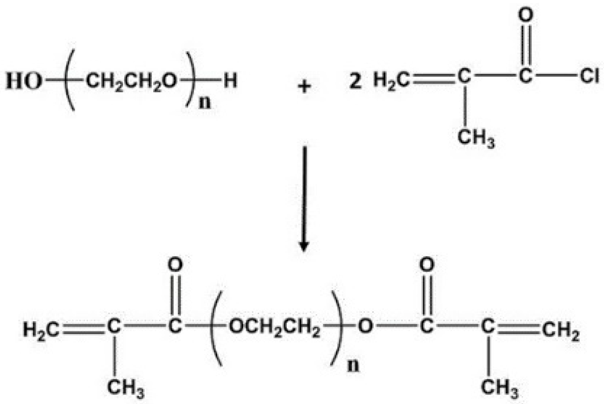
2.2.1. Synthesis of the PEG Macro Crosslinker
2.2.2. Synthesis of the Crosslinked PS-b-PEG Block Copolymers
2.3. Characterization
2.3.1. FTIR Spectra
2.3.2. 1H NMR Spectra
2.3.3. Thermo Gravimetric Analysis (TGA)
2.3.4. Scanning Electron Micrographs (SEM)
2.4. Preparation of the PbO Doped the Crosslinked PS-b-PEG Block Copolymers and the PbO Doped the PS-b-PEG-BN Nanocomposite Materials
2.5. Gamma Ray Attenuation Measurements
3. Results and Discussions
3.1. Constructional Information of Samples
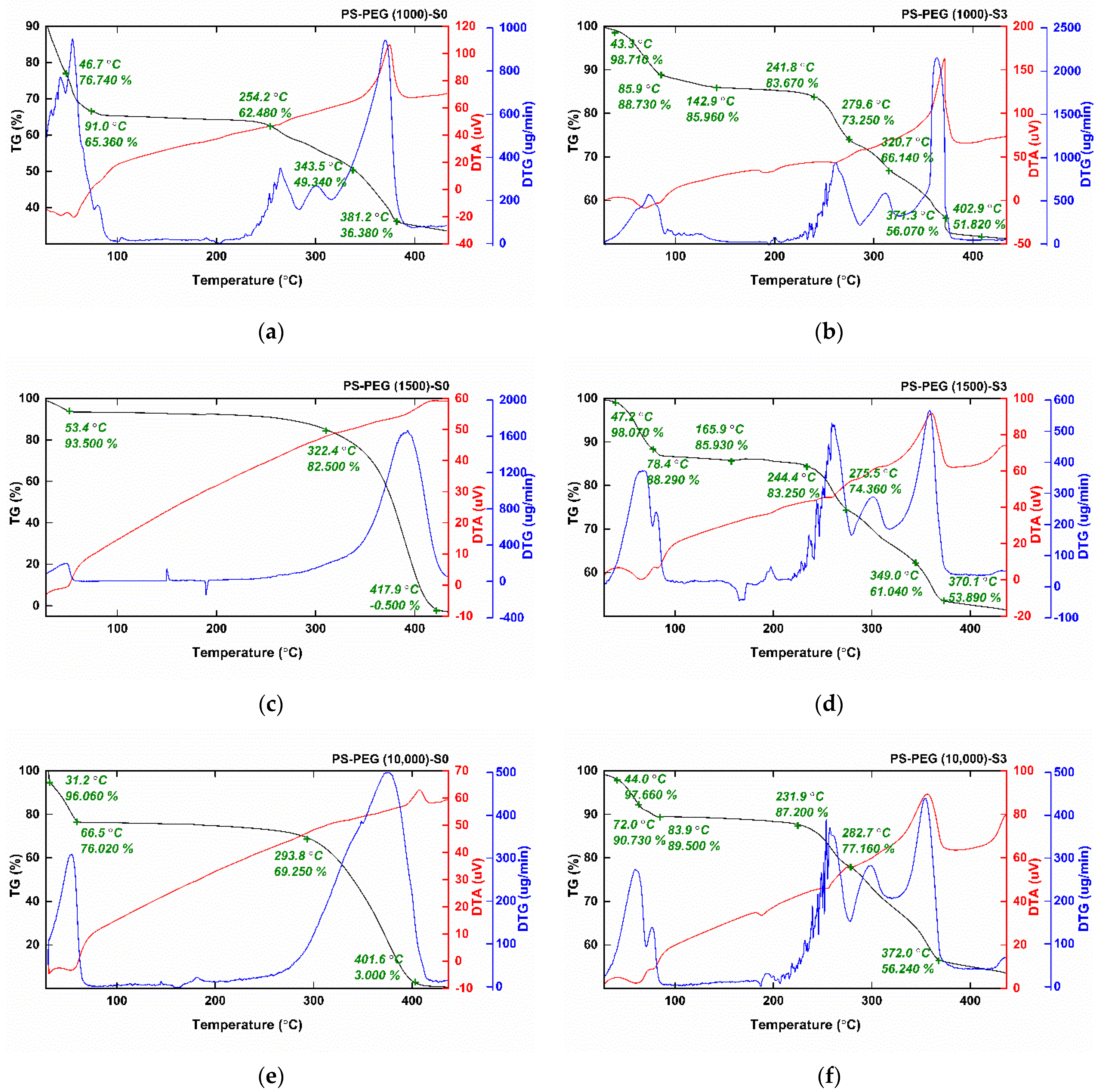
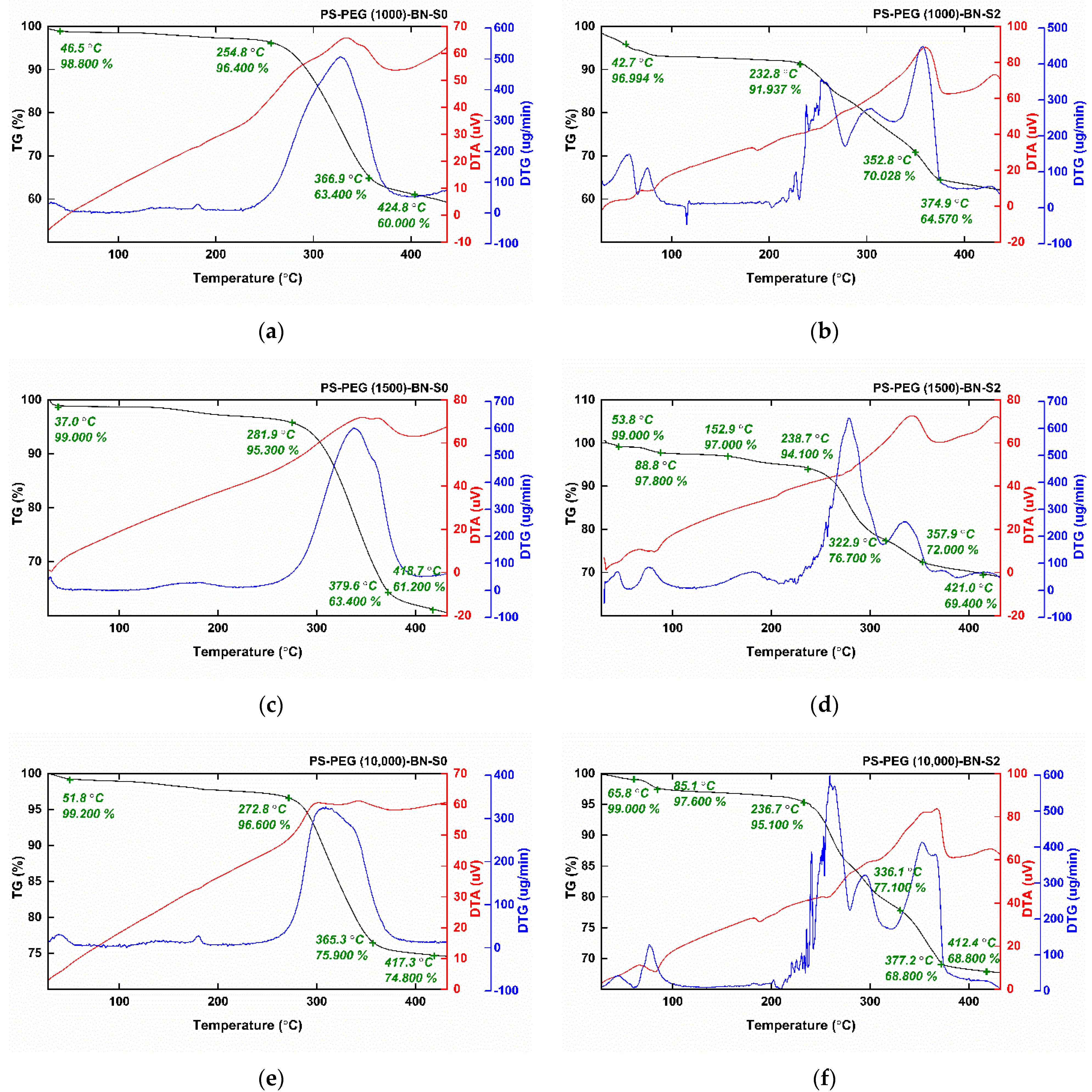
3.1.1. Thermogravimetric Analysis (TGA) of the PbO Doped the Crosslinked PS-b-PEG Block Copolymers and the PbO Doped the PS-b-PEG Nanocomposite Materials
3.1.2. Morphological Characterization of the PbO Doped the Crosslinked PS-b-PEG Block Copolymers and the PbO Doped the PS-b-PEG Nanocomposite Materials
3.2. Gamma-Ray Attenuation Characteristics of the PbO Doped the Crosslinked PS-b-PEG Block Copolymers and the PbO Doped the PS-b-PEG-BN Nanocomposite Materials
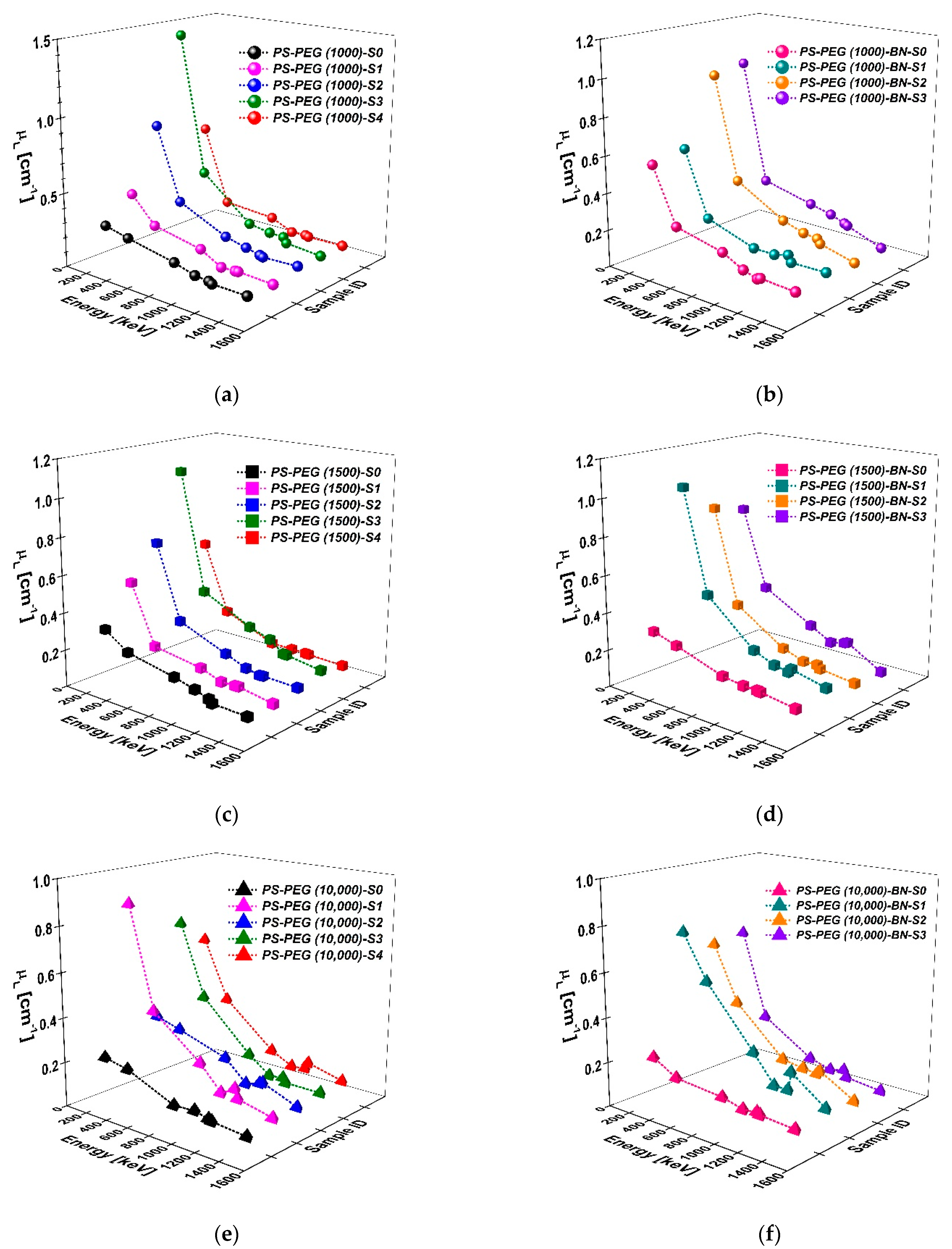
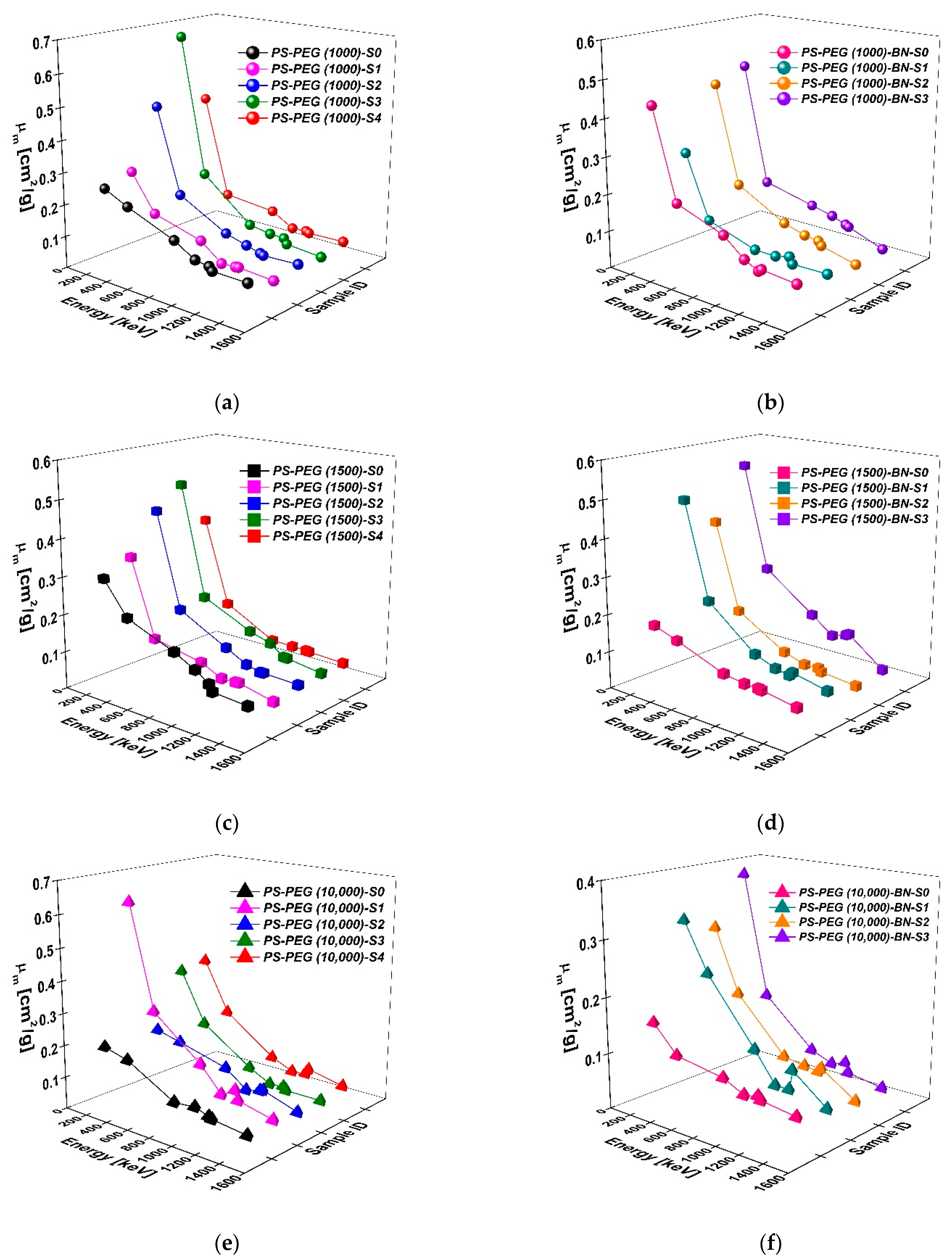
3.2.1. Linear () and Mass Attenuation () Coefficients
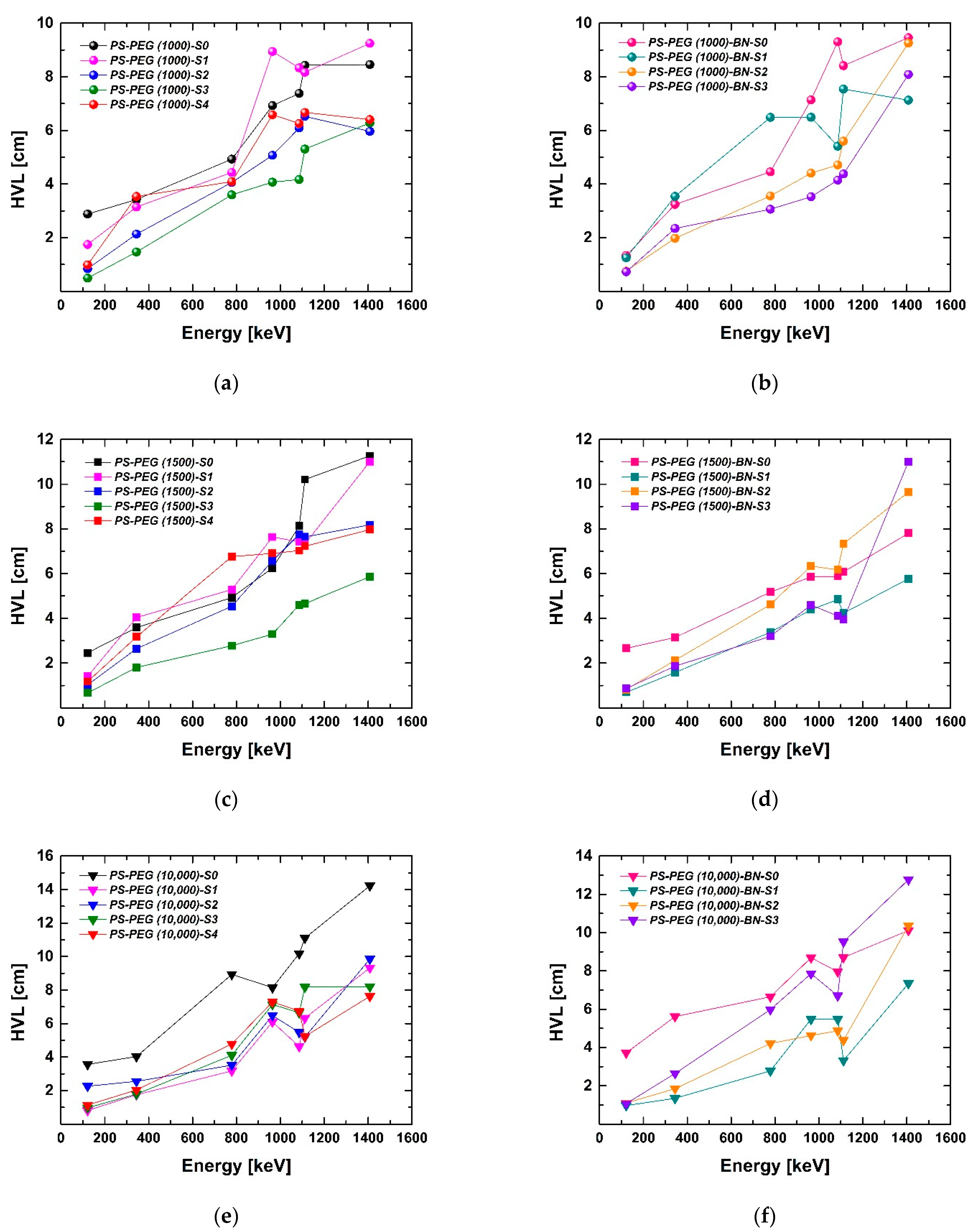
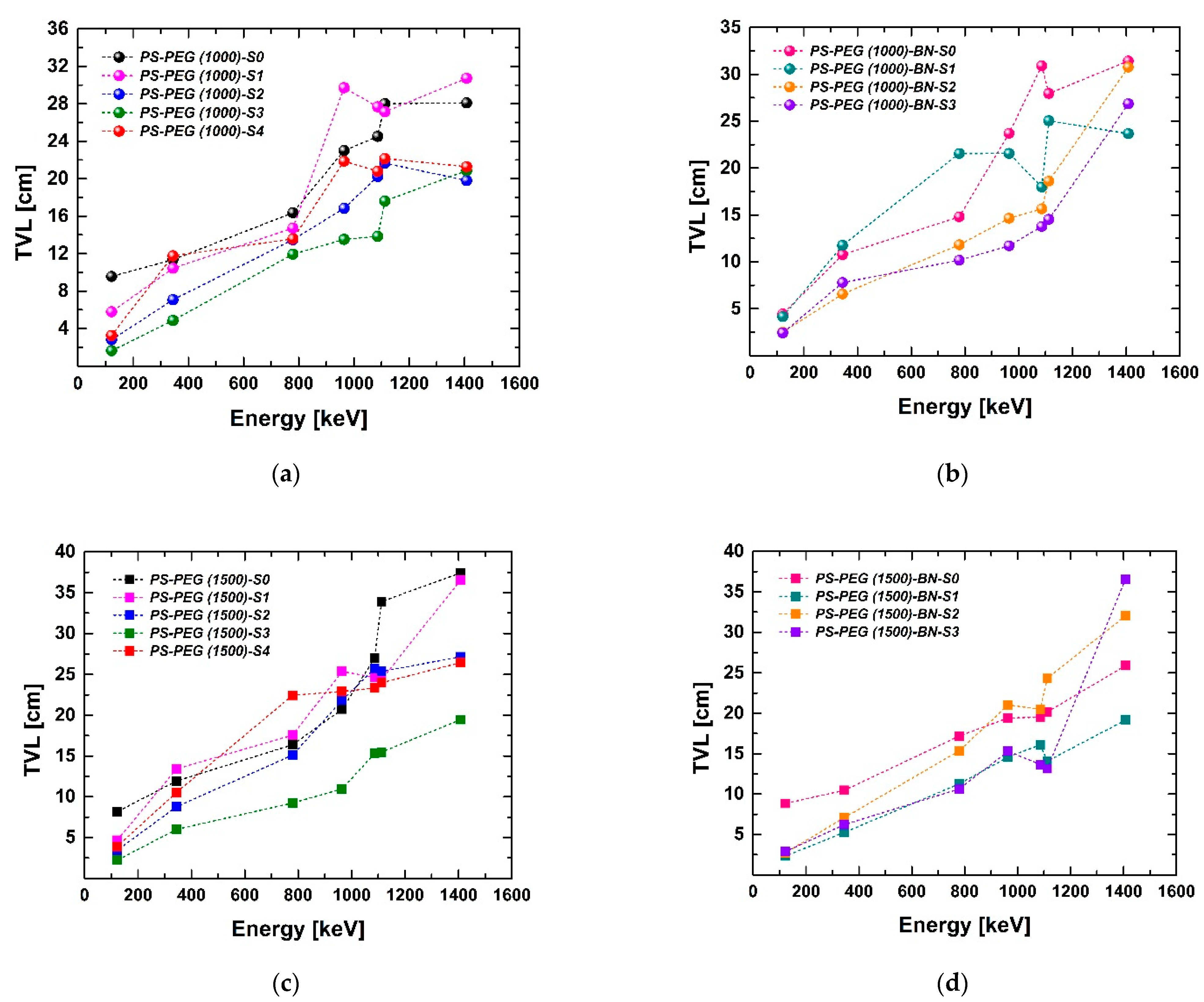
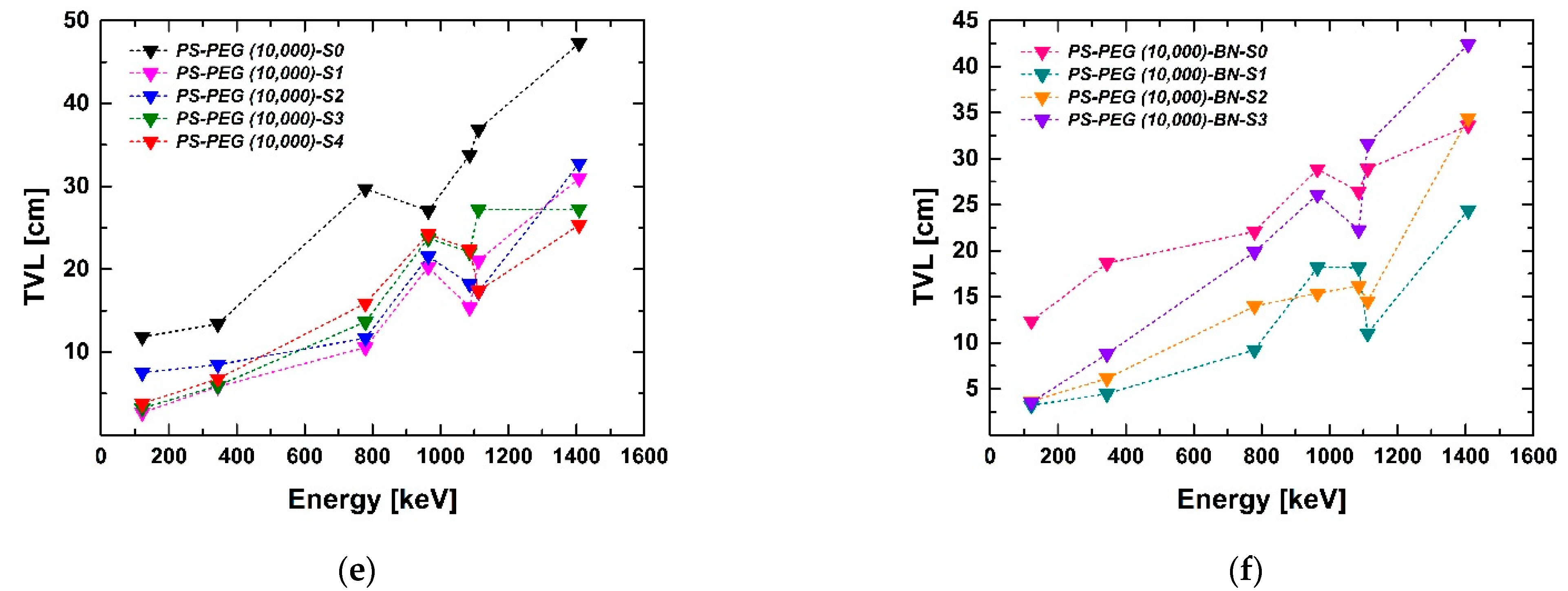
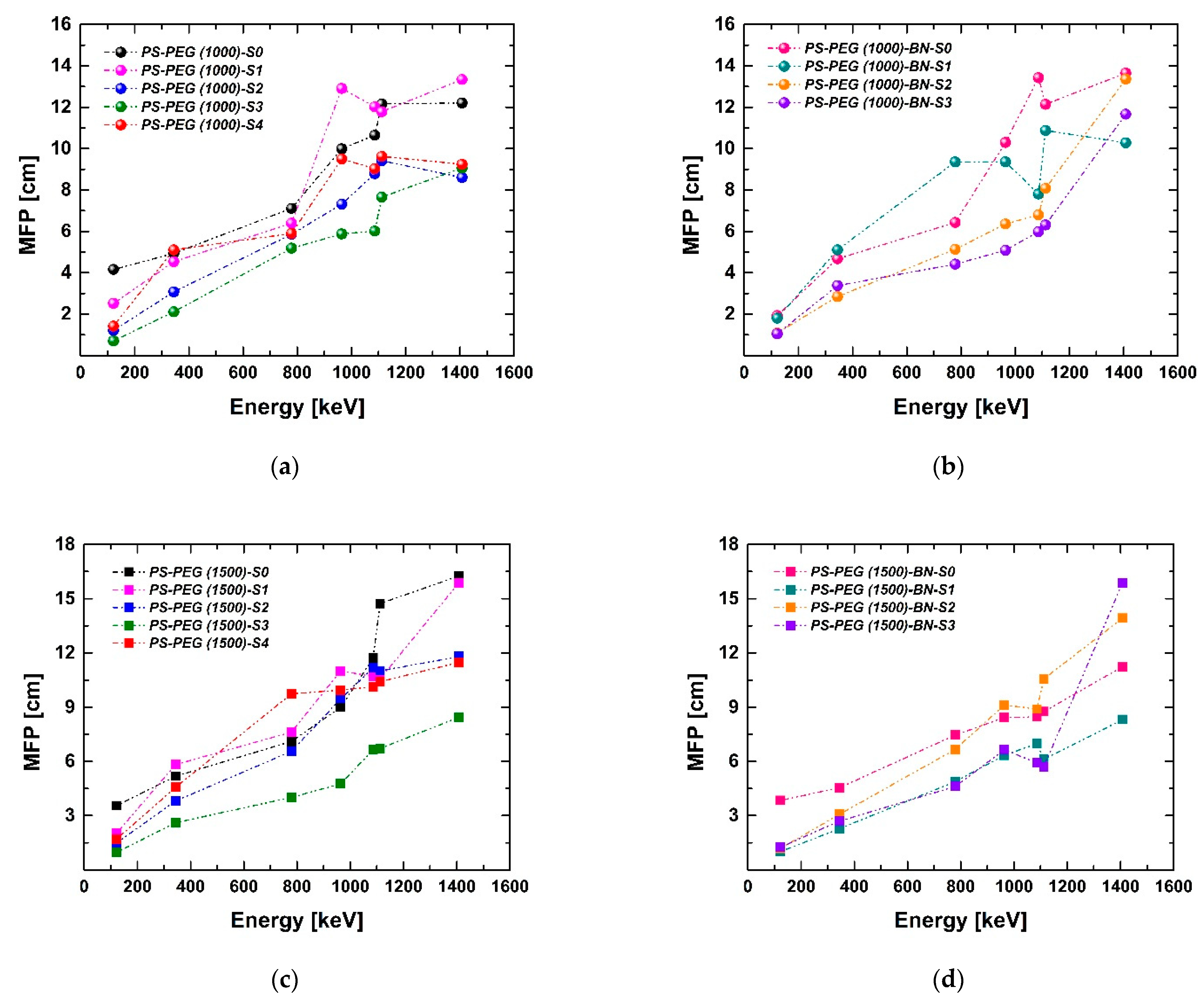
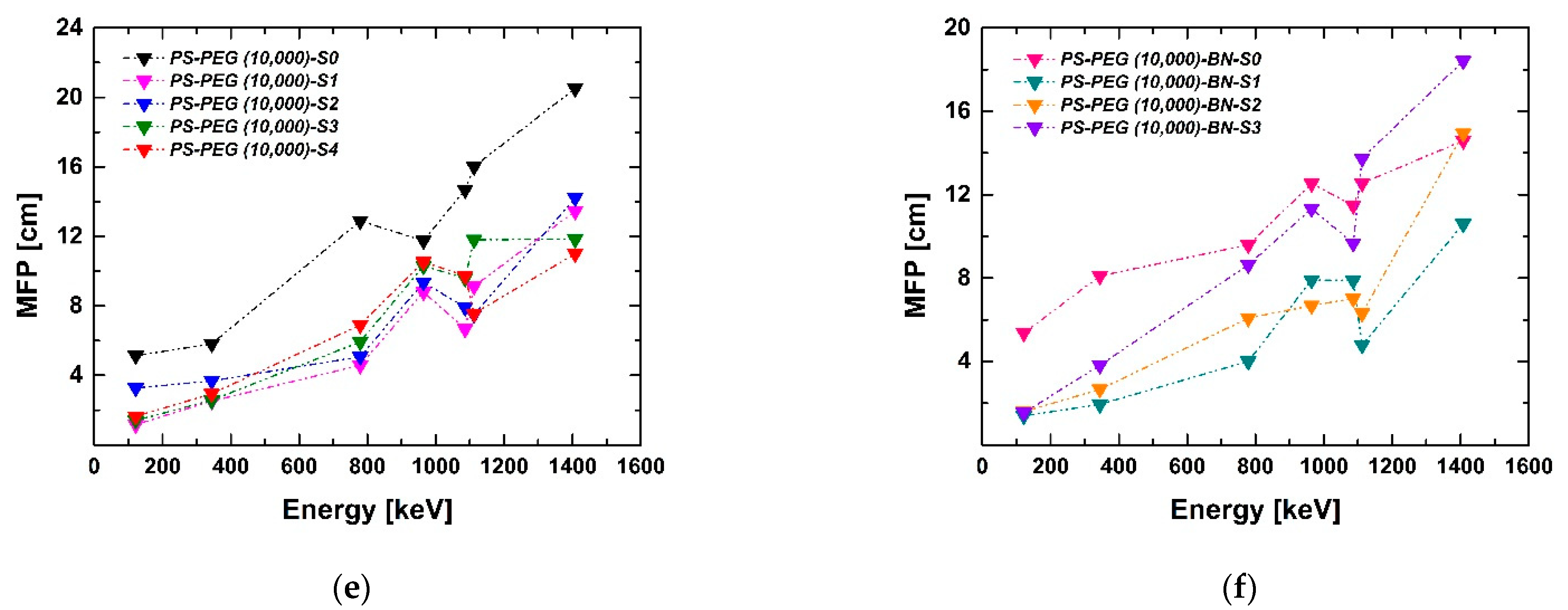
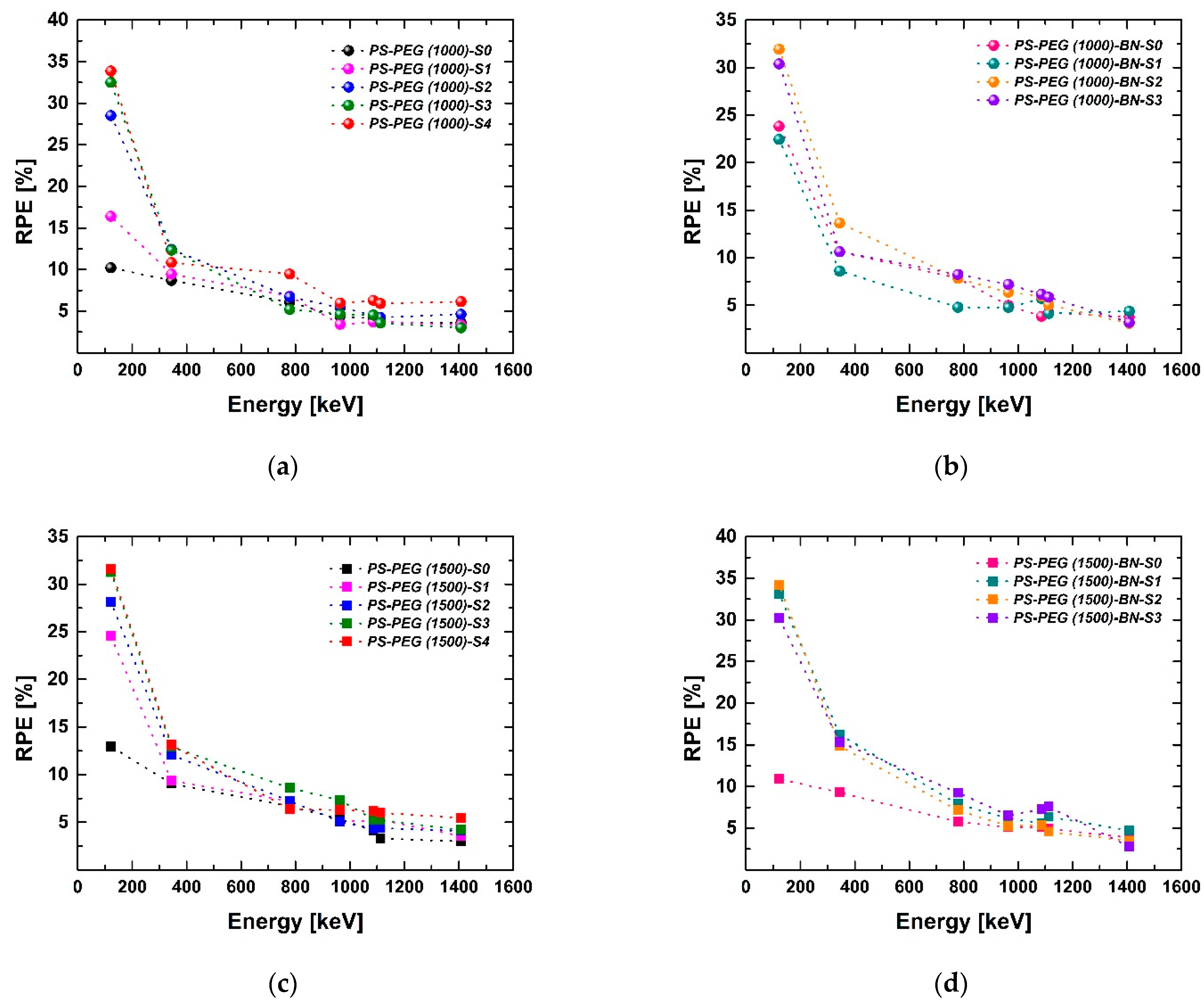
3.2.2. Half-Value Layer (HVL), Tenth Value Layer (TVL), Mean Free Path (MFP), and Radiation Protection Efficiency (RPE)
4. Conclusions and Future Perspectives
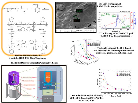
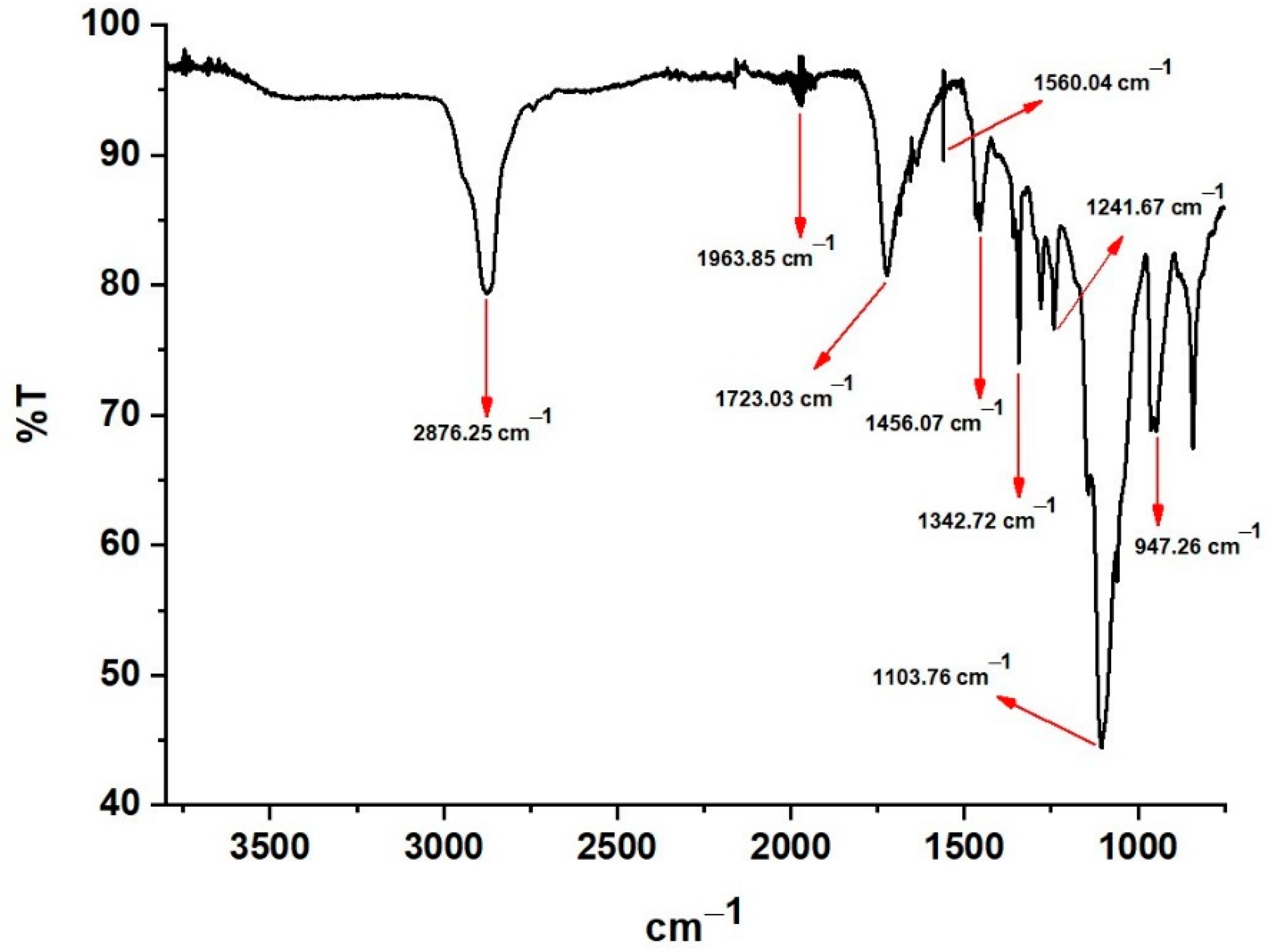
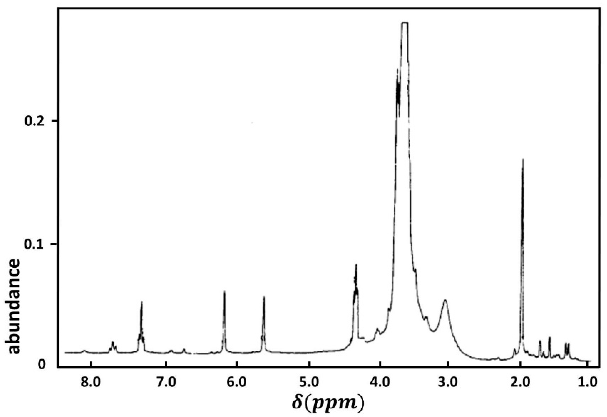
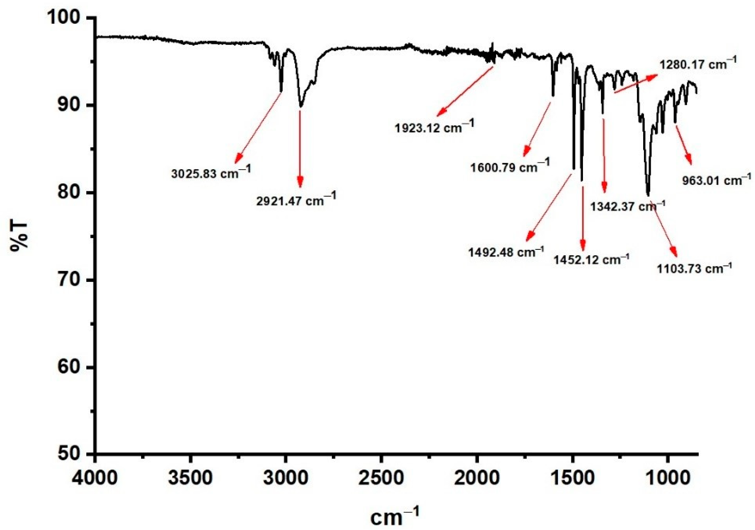
- The polystyrene-co-polyethyleneglycol (PS-PEG) crosslinked block copolymers were constructed from styrene copolymerization by either polyethyleneglycol (PEG) macro crosslinker by using emulsion polymerization under vacuum in the Schlenk system. values of polyethyleneglycol of PEG were 1000 and 1500. The characterization of the block copolymer was made with the NMR, IR, TGA, and SEM methods. The IR (cm−1), 1723.03 (C=O), 1560.04 (C=C), 1103.76 (C–O–C), NMR (δ, ppm); 2.0 (CH3), 3.5 (–CH2–O–CH2), and 5.6-6.2 (vinylic protons). The IR peaks as cm−1 in the FTIR spectrum of the crosslinked PS-b-PEG block copolymers are followed: methylene group CH stretching vibrations at 2921.47, benzene ring C=C stretching vibrations at 1600.79, benzene ring overtone band combinations at 1600.79 and 1452.12, –C (C=O) stretching vibrations at 1280.17, and –OCC groups asymmetric stretching vibrations at 1103.73.
- The outcomes of TGA thermograms of the PbO doped the crosslinked PS-b-PEG block copolymers and the PbO doped the PS-b-PEG-BN nanocomposite materials, it is seen that the implemented radiation does not influence the structure of the investigated polymer-based composites. From all TGA results; it can be concluded that PbO increases the durability of the copolymer and BN increases the thermal durability of the copolymer.
- The HVL values of our samples provide persuasive instructions regarding the shielding capacity of our materials, declining the photon amount to half of the present status concerning the thickness of the samples. The acquired values represent that the MFP of materials ascents with photon energy. Additionally, the MFP value is one of the substantial variables that understandably clarifies the gamma radiation deterioration abilities of the shielding substances used. The smaller the MFP rates, the preferable the shielding competence of the material. Our outcomes demonstrate that the MFP rates of our samples are ascent with photon energy. It has been observed that the measured and calculated values show changes with the change of the polymer type used to improve the gamma radiation shielding materials. In addition, it was observed that the radiation protection capacities of the samples improved when the PbO or BN percentages of the prepared materials were changed. When the HVL, TVL, MFP, and RPE results of our all samples are examined with a broad perspective, it can be emphasized that these samples developed in our research reveal important and reliable results to enlighten radiation shielding studies. We observed in our results that the lower the HVL, TVL, and MFP values of any sample, the better the radiation shielding efficiency due to the lower thickness necessities, and the higher the RPE values of any sample, the better the radiation shielding efficiency, i.e., we concluded from our results that the lower the HVL, TVL, and MFP values of any sample, the better the RPE due to the lower thickness necessities.
- It has been observed that the measured and calculated values show changes with the change of the polymer type used to improve the gamma radiation shielding materials. In addition, it was observed that the radiation protection capacities of the samples improved when the PbO or BN percentages of the prepared materials were changed. When we compare all samples, we can deduce that the bigger LACs and MACs rates and ideal absorption of gamma photons are owing to the high percentage rates of PbO ingredients in the substances. If the LACs and MACs results of our all samples are examined with a broad perspective, we can emphasize that these samples developed in our research reveal important and reliable results to enlighten radiation shielding studies. Furthermore, BN was added to our nanocomposites because the neutron absorption property of BN is known. It is expected that this important point will be investigated in further studies and its neutron absorber property will be observed.
Supplementary Materials
Author Contributions
Funding
Institutional Review Board Statement
Informed Consent Statement
Data Availability Statement
Conflicts of Interest
References
- Al-Buriahi, M.S.; Eke, C.; Alomairy, S.; Yildirim, A.; Alsaeedy, H.I.; Sriwunkum, C. Radiation attenuation properties of some commercial polymers for advanced shielding applications at low energies. Polym. Adv. Technol. 2021, 32, 2386–2396. [Google Scholar] [CrossRef]
- Sukesh Babu, M.; Sarathi, R.; Imai, T.; Tanaka, T. Influence of Gamma Irradiation and Water Aging on the Space Charge Characteristics of Epoxy Micro-Nano Composites. Polymers 2021, 13, 964. [Google Scholar] [CrossRef]
- Poltabtim, W.; Toyen, D.; Saenboonruang, K. Theoretical Determination of High-Energy Photon Attenuation and Recommended Protective Filler Contents for Flexible and Enhanced Dimensionally Stable Wood/NR and NR Composites. Polymers 2021, 13, 869. [Google Scholar] [CrossRef]
- Saenboonruang, K.; Poltabtim, W.; Thumwong, A.; Pianpanit, T.; Rattanapongs, C. Rare-Earth Oxides as Alternative High-Energy Photon Protective Fillers in HDPE Composites: Theoretical Aspects. Polymers 2021, 13, 1930. [Google Scholar] [CrossRef]
- Joseph, B.B. The road to radiation safety and ALARA: A review. Int. J. Maxillofac Imaging 2020, 6, 89–92. [Google Scholar] [CrossRef]
- Bryant, P.A. Communicating radiation risk: The role of public engagement in reaching ALARA. J. Radiol. Prot. 2021, 41, S1–S8. [Google Scholar] [CrossRef]
- Oakley, P.E.; Harrison, D.E. Death of the ALARA Radiation Protection Principle as Used in the Medical Sector. Dose-Response. 2020, 18, 1559325820921641. [Google Scholar] [CrossRef] [PubMed]
- Jones, C.G. The US Nuclear Regulatory Commission radiation protection policy and opportunities for the future. J. Radiol. Prot. 2019, 39, 51–62. [Google Scholar] [CrossRef] [PubMed]
- Lakshminarayana, G.; Elmahroug, Y.; Kumar, A.; Tekin, H.O.; Rekik, N.; Dong, M.; Lee, D.-E.; Yoon, J.; Park, T. Detailed Inspection of γ-ray, Fast and Thermal Neutrons Shielding Competence of Calcium Oxide or Strontium Oxide Comprising Bismuth Borate Glasses. Materials 2021, 14, 2265. [Google Scholar] [CrossRef] [PubMed]
- Tekin, H.O.; Issa, S.A.M.; Kilic, G.; Zakaly, H.M.H.; Abuzaid, M.M.; Tarhan, N.; Alshammari, K.; Sidek, H.A.A.; Matori, K.A.; Zaid, M.H.M. In-Silico Monte Carlo Simulation Trials for Investigation of V2O5 Reinforcement Effect on Ternary Zinc Borate Glasses: Nuclear Radiation Shielding Dynamics. Materials 2021, 14, 1158. [Google Scholar] [CrossRef]
- Wu, Y.; Cao, Y.; Wu, Y.; Li, D. Mechanical Properties and Gamma-Ray Shielding Performance of 3D-Printed Poly-Ether-Ether-Ketone/Tungsten Composites. Materials 2020, 13, 4475. [Google Scholar] [CrossRef]
- Sayyed, M.I.; Mohammed, F.Q.; Mahmoud, K.A.; Lacomme, E.; Kaky, K.M.; Khandaker, M.U.; Faruque, M.R.I. Evaluation of Radiation Shielding Features of Co and Ni-Based Superalloys Using MCNP-5 Code: Potential Use in Nuclear Safety. Appl. Sci. 2020, 10, 7680. [Google Scholar] [CrossRef]
- Sayyed, M.I.; Mahmoud, K.A.; Tashlykov, O.L.; Khandaker, M.U.; Faruque, M.R.I. Enhancement of the Shielding Capability of Soda-Lime Glasses with Sb2O3 Dopant: A Potential Material for Radiation Safety in Nuclear Installations. Appl. Sci. 2021, 11, 326. [Google Scholar] [CrossRef]
- Tekin, H.O.; Issa, S.A.M.; Kilic, G.; Zakaly, H.M.H.; Tarhan, N.; Sidek, H.A.A.; Matori, K.A.; Zaid, M.H.M. A Systematical Characterization of TeO2-V2O5 Glass System Using Boron (III) Oxide and Neodymium (III) Oxide Substitution: Resistance Behaviors against Ionizing Radiation. Appl. Sci. 2021, 11, 3035. [Google Scholar] [CrossRef]
- Almuqrin, A.H.; Sayyed, M.I. Gamma Ray Shielding Properties of Yb3+-Doped Calcium Borotellurite Glasses. Appl. Sci. 2021, 11, 5697. [Google Scholar] [CrossRef]
- Wei, H.; Lou, L.; Yang, Z.; He, R.; Fan, J.; Zhang, K.; Yang, W. Multifunctional composites silicone rubber/paraffin@lead tungstate with different core/shell ratio for thermal regulation and gamma shielding. J. Energy Storage 2021, 36, 102363. [Google Scholar] [CrossRef]
- Temir, A.; Sh Zhumadilov, K.; Zdorovets, M.V.; Korolkov, I.V.; Kozlovskiy, A.; Trukhanov, A.V. Synthesis, phase transformations, optical properties and efficiency of gamma radiation shielding by Bi2O3-TeO2-WO3 ceramics. Opt. Mater. 2021, 113, 110846. [Google Scholar] [CrossRef]
- Baalamurugan, J.; Ganesh Kumar, V.; Chandrasekaran, S.; Balasundar, S.; Venkatraman, B.; Padmapriya, R.; Bupesh Raja, V.K. Recycling of steel slag aggregates for the development of high density concrete: Alternative & environment-friendly radiation shielding composite. Compos. B. Eng. 2021, 216, 108885. [Google Scholar] [CrossRef]
- Yastrebinsky, R.N.; Pavlenko, V.I.; Karnauhov, A.A.; Cherkashina, N.I.; Yastrebinskaya, A.V.; Gorodov, A.I. Radiation Resistance of a Structural Material Based on Modified Titanium Hydride. Sci. Technol. Nucl. Install. 2021, 2021, 6658431. [Google Scholar] [CrossRef]
- Wie, J.; Kim, J. Thermal Properties of Surface-Modified and Cross-Linked Boron Nitride/Polyethylene Glycol Composite as Phase Change Material. Polymers 2021, 13, 456. [Google Scholar] [CrossRef]
- Sobolčiak, P.; Mrlik, M.; Popelka, A.; Minařík, A.; Ilcikova, M.; Srnec, P.; Nogellova, Z.; Ouederni, M.; Krupa, I. Foamed Phase Change Materials Based on Recycled Polyethylene/Paraffin Wax Blends. Polymers 2021, 13, 1987. [Google Scholar] [CrossRef]
- Susilawati, S.; Prayogi, S.; Arif, M.F.; Ismail, N.M.; Bilad, M.R.; Asy’ari, M. Optical Properties and Conductivity of PVA-H3PO4 (Polyvinyl Alcohol-Phosphoric Acid) Film Blend Irradiated by γ-Rays. Polymers 2021, 13, 1065. [Google Scholar] [CrossRef]
- El-Taher, A.; Zakaly, H.M.H.; Pyshkina, M.; Allam, E.A.; El-Sharkawy, R.M.; Mahmoud, M.E.; Abdel-Rahman, M.A.E. A comparative Study between Fluka and Microshield Modeling Calculations to study the Radiation-Shielding of Nanoparticles and Plastic Waste composites. Z. Anorg. Allg. Chem. 2021, 647, 1083. [Google Scholar] [CrossRef]
- Mehrara, R.; Malekie, S.; Kotahi, S.M.S.; Kashian, S. Introducing a novel low energy gamma ray shield utilizing Polycarbonate Bismuth Oxide composite. Sci. Rep. 2021, 11, 10614. [Google Scholar] [CrossRef] [PubMed]
- Ayub, S.; Guan, B.H.; Ahmad, F.; Javed, M.F.; Mosavi, A.; Felde, I. Preparation Methods for Graphene Metal and Polymer Based Composites for EMI Shielding Materials: State of the Art Review of the Conventional and Machine Learning Methods. Metals 2021, 11, 1164. [Google Scholar] [CrossRef]
- Barala, S.S.; Manda, V.; Jodha, A.S.; Meghwal, L.R.; Gopalani, D. Ethylene-propylene diene monomer-based polymer composite for attenuation of high energy radiations. J. Appl. Polym. Sci. 2021, 138, e50334. [Google Scholar] [CrossRef]
- Cherkashina, N.I.; Pavlenko, V.I.; Noskov, A.V.; Sirota, V.V.; Zaitsev, S.V.; Prokhorenkov, D.S.; Sidelnikov, R.V. Gamma radiation attenuation characteristics of polyimide composite with WO2. Prog. Nucl. Energy. 2021, 137, 103795. [Google Scholar] [CrossRef]
- Hassan, H.E.; Badran, H.M.; Aydarous, A.; Sharshar, T. Studying the effect of nano lead compounds additives on the concrete shielding properties for γ-rays. Nuc.l Instrum. Methods Phys. Res. B 2015, 360, 81–89. [Google Scholar] [CrossRef]
- Kozlovskiy, A.; Zdorovets, M.V.; Kadyrzhanov, K.K. Study of physical, optical properties and gamma radiation shielding efficiency of 0.5Bi2O3-(0.5-x)WO3-xPbO glasses. Opt. Mater. B. 2021, 114, 111005. [Google Scholar] [CrossRef]
- Mahmoud, K.A.; El-Agawany, F.I.; Tashlykov, O.L.; Ahmed, E.M.; Rammah, Y.S. The influence of BaO on the mechanical and gamma/fast neutron shielding properties of lead phosphate glasses. Nucl. Eng. Technol. 2021, (in press). [Google Scholar] [CrossRef]
- Mokhtaria, K.; Kheradmand Saadi, M.; Ahmadpanahi, H.; Jahanfarnia, G. Fabrication, characterization, simulation and experimental studies of the ordinary concrete reinforced with micro and nano lead oxide particles against gamma radiation. Nucl. Eng. Technol. 2021, 53, 3051–3057. [Google Scholar] [CrossRef]
- Othman, S.A. Effect of lead oxide on concrete density for radiation shielding purposes. IOP Conf. Ser.: Mater. Sci. Eng. 2021, 1106, 012011. [Google Scholar] [CrossRef]
- Qian, Z.; Cai, J.; Li, C.; Zhang, Z.; Wang, J. Influence of PbO content on the gamma ray shielding properties of lead boro-telluro-phosphate glasses. Radiat. Phys. Chem. 2021, 185, 109516. [Google Scholar] [CrossRef]
- Alotaibi, B.M.; Sayyed, M.I.; Kumar, A.; Alotiby, M.; Sharma, A.; Al-Yousef, H.A.; Alsaif, N.A.M.; Al-Hadeethi, Y. Optical and gamma-ray shielding effectiveness of a newly fabricated P2O5-CaO-Na2O-K2O-PbO glass system. Prog. Nucl. Energy 2021, 138, 103798. [Google Scholar] [CrossRef]
- Alzahrani, J.S.; Kavas, T.; Kurtulus, R.; Olarinoye, I.O.; Al-Buriahi, M.S. Physical, structural, mechanical, and radiation shielding properties of the PbO-B2O3-Bi2O3-ZnO glass system. J. Mater. Sci. Mater. Electron. 2021, 32, 18994–19009. [Google Scholar] [CrossRef]
- El-Mallawany, R.; Kavaz, E.; Perişanoğlu, U.; Tekin, H.O.; Alazoumi, S.H.; Umar, S.A.; El-Agawany, F.I.; Rammah, Y.S. New shielding ZnO-PbO-TeO2 glasses. Optik 2021, 243, 167483. [Google Scholar] [CrossRef]
- Al-Harbi, N.; Sayyed, M.I.; Kumar, A.; Mahmoud, K.A.; Olarinoye, O.I.; Alhuthali, A.M.S.; Al-Hadeethi, Y. A comprehensive investigation on the role of PbO in the structural and radiation shielding attribute of P2O5-CaO-Na2O-K2O-PbO glass system. J. Mater. Sci.: Mater. Electron. 2021, 32, 12371–12382. [Google Scholar] [CrossRef]
- Al-Buriahi, M.S.; Alzahrani, J.S.; Olarinoye, I.O.; Mutuwong, C.; Elsaeedy, H.I.; Alomairy, S.; Tonguc, B.T. Effects of reducing PbO content on the elastic and radiation attenuation properties of germanate glasses: A new non-toxic candidate for shielding applications. J. Mater. Sci.: Mater. Electron. 2021, 32, 15080–15094. [Google Scholar] [CrossRef]
- Stalin, S.; Gaikwad, D.K.; Al-Buriahi, M.S.; Srinivasu, C.; Ahmed, S.A.; Tekin, H.O.; Rahman, S. Influence of Bi2O3/WO3 substitution on the optical, mechanical, chemical durability and gamma ray shielding properties of lithium-borate glasses. Ceram. Int. 2021, 47, 5286–5299. [Google Scholar] [CrossRef]
- Algradee, M.A.; Saleh, E.E.; EL Sherbini, T.M.; El-Mallawany, R. Optical and gamma-ray shielding features of Nd3+ doped lithium-zinc-borophosphate glasses. Optik 2021, 242, 167059. [Google Scholar] [CrossRef]
- Jiao, L.; Wang, Y.; Wu, Z.; Shen, H.; Weng, H.; Chen, H.; Huang, W.; Wang, M.; Ge, X.; Lin, M. Effect of gamma and neutron irradiation on properties of boron nitride/epoxy resin composites. Polym. Degrad. Stab. 2021, 190, 109643. [Google Scholar] [CrossRef]
- Fu, X.; Ji, Z.; Lin, W.; Yu, Y.; Wu, T. The Advancement of Neutron Shielding Materials for the Storage of Spent Nuclear Fuel. Sci. Technol. Nucl. Install. 2021, 2021, 5541047. [Google Scholar] [CrossRef]
- Issa, S.A.M.; Kumar, A.; Sayyed, M.I.; Dong, M.G.; Elmahroug, Y. Mechanical and gamma-ray shielding properties of TeO2-ZnO-NiO glasses. Mater. Chem. Phys. 2018, 212, 12–20. [Google Scholar] [CrossRef]
- Sharifi, S.; Bagheri, R.; Shirmardi, S.P. Comparison of shielding properties for ordinary, barite, serpentine and steel magnetite concretes using MCNP-4C code and available experimental results. Ann. Nucl. Energy. 2013, 53, 529–534. [Google Scholar] [CrossRef]
- Singh, M.P.; Sandhu, B.S.; Singh, B. Measurement of the effective atomic number of composite materials using Rayleigh to Compton scattering of 279 keV gamma rays. Phys. Scr. 2007, 76, 281. [Google Scholar] [CrossRef]
- Issa, S.A.M.; Tekin, H.O.; Erguzel, T.T.; Susoy, G. The effective contribution of PbO on nuclear shielding properties of xPbO- (100-x)P2O5 glass system: A broad range investigation. Appl. Phys. A. 2019, 125, 640. [Google Scholar] [CrossRef]
- Mahmoud, K.A.; Sayyed, M.I.; Tashlykov, O.L. Gamma ray shielding characteristics and exposure buildup factor for some natural rocks using MCNP-5 code. Nucl. Eng. Technol. 2019, 51, 1835–1841. [Google Scholar] [CrossRef]
- Kiani, M.A.; Ahmadi, S.J.; Outokesh, M.; Adeli, R.; Kiani, H. Study on physico-mechanical and gamma-ray shielding characteristics of new ternary nanocomposites. Appl. Radiat. Isot. 2019, 143, 141–148. [Google Scholar] [CrossRef] [PubMed]
- Berger, M.J.; Hubbell, J.H.; Seltzer, S.M.; Chang, J.; Coursey, J.S.; Sukumar, R.; Zucker, D.S.; Olsen, K. XCOM: Photon Cross Sections Database-NIST Standard Reference Database 8 (XGAM). NIST PML Radiat. Phys. Div. NBSIR 2010, 3587–3597. [Google Scholar] [CrossRef]
- Gerward, L.; Guilbert, N.; Jensen, K.B.; Levring, H. X-ray absorption in matter reengineering XCOM. Radiat. Phys. Chem. 2001, 60, 23–24. [Google Scholar] [CrossRef]
- Gerward, L.; Guilbert, N.K.; Jensen, B.; Levring, H. WinXCom—A program for calculating X-ray attenuation coefficients. Radiat. Phys. Chem. 2004, 71, 653–654. [Google Scholar] [CrossRef]
- Savaskan, S. Synthesis and Investigation of Ion Exchange Properties of New Ion Exchangers. Ph.D. Thesis, Graduate School of Natural and Applied Sciences Institute, Chemistry Department, KTU, Trabzon, Turkey, March 1994. [Google Scholar]
- Savaşkan, S.; Besşirli, N.; Hazer, B. Synthesis of some new cation-exchanger resins. J. Appl. Polym. Sci. 1996, 59, 1515–1524. [Google Scholar] [CrossRef]
- Savaskan Yilmaz, S.; Yildirim, N.; Misir, M.; Misirlioglu, Y.; Celik, E. Synthesis, Characterization of a New Polyacrylic Acid Superabsorbent, Some Heavy Metal Ion Sorption, the Adsorption Isotherms, and Quantum Chemical Investigation. Materials 2020, 13, 4390. [Google Scholar] [CrossRef] [PubMed]
- Savaskan Yilmaz, S.; Kul, D.; Erdöl, M.; Özdemir, M.; Abbasoğlu, R. Synthesis of a novel crosslinked superabsorbent copolymer with diazacyclooctadecane crown ether and its sorption capability. Eur. Polym. J. 2007, 43, 1923–1932. [Google Scholar] [CrossRef]
- Cinan, Z.M.; Baskan, T.; Erol, B.; Mutlu, S.; Misirlioglu, Y.; Savaskan Yilmaz, S.; Yilmaz, A.H. Gamma Irradiation, Thermal Conductivity and Phase Change Tests of The Cement-Hyperbranched Poly Amino-Ester-block-Poly Cabrolactone-Polyurathane Plaster-Lead Oxide and Arsenic Oxide Composite for Development of Radiation Shielding Material. Int. J. Energy Res. 2021, 2021, 1–34. [Google Scholar] [CrossRef]
- Almuqrin, A.H.; Albarzan, B.; Olarinoye, O.I.; Kumar, A.; Alwadai, N.; Sayyed, M.I. Mechanical and Gamma Ray Absorption Behavior of PbO-WO3-Na2O-MgO-B2O3 Glasses in the Low Energy Range. Materials 2021, 14, 3466. [Google Scholar] [CrossRef] [PubMed]


| Sample ID | PS-b-PEG (wt%) | BN (wt%) | PbO (wt%) |
|---|---|---|---|
| PS-PEG (1000)-S0 | 100 | 0 | 0 |
| PS-PEG (1000)-S1 | 50 | 0 | 50 |
| PS-PEG (1000)-S2 | 30 | 0 | 70 |
| PS-PEG (1000)-S3 | 10 | 0 | 90 |
| PS-PEG (1000)-S4 | 46.2 | 0 | 53.8 |
| PS-PEG (1500)-S0 | 100 | 0 | 0 |
| PS-PEG (1500)-S1 | 50 | 0 | 50 |
| PS-PEG (1500)-S2 | 30 | 0 | 70 |
| PS-PEG (1500)-S3 | 10 | 0 | 90 |
| PS-PEG (1500)-S4 | 46.2 | 0 | 53.8 |
| PS-PEG (10,000)-S0 | 100 | 0 | 0 |
| PS-PEG (10,000)-S1 | 50 | 0 | 50 |
| PS-PEG (10,000)-S2 | 30 | 0 | 70 |
| PS-PEG (10,000)-S3 | 10 | 0 | 90 |
| PS-PEG (10,000)-S4 | 46.2 | 0 | 53.8 |
| PS-PEG (1000)-BN-S0 | 50 | 50 | 0 |
| PS-PEG (1000)-BN-S1 | 15 | 15 | 70 |
| PS-PEG (1000)-BN-S2 | 5 | 5 | 90 |
| PS-PEG(1000)-BN-S3 | 26.1 | 13 | 60.9 |
| PS-PEG (1500)-BN-S0 | 50 | 50 | 0 |
| PS-PEG (1500)-BN-S1 | 15 | 15 | 70 |
| PS-PEG (1500)-BN-S2 | 5 | 5 | 90 |
| PS-PEG (1500)-BN-S3 | 26.1 | 13 | 60.9 |
| PS-PEG (10,000)-BN-S0 | 50 | 50 | 0 |
| PS-PEG (10,000)-BN-S1 | 15 | 15 | 70 |
| PS-PEG (10,000)-BN-S2 | 5 | 5 | 90 |
| PS-PEG (10,000)-BN-S3 | 26.1 | 13 | 60.9 |
| PS-PEG (1000)-S0 | PS-PEG (1000)-S3 | PS-PEG (1000)-BN-S0 | PS-PEG (1000)-BN-S2 | ||||
| Temperature (°C) | wt (%) | Temperature (°C) | wt (%) | Temperature (°C) | wt (%) | Temperature (°C) | wt (%) |
| 46.7 | 76.740 | 43.3 | 98.710 | 46.5 | 98.800 | 42.7 | 96.994 |
| 91.0 | 65.360 | 85.9 | 88.730 | 254.8 | 96.400 | 232.8 | 91.937 |
| 254.2 | 62.480 | 142.9 | 85.960 | 366.9 | 63.400 | 352.8 | 70.028 |
| 343.5 | 49.340 | 241.8 | 83.670 | 424.8 | 60.00 | 374.9 | 64.570 |
| 381.2 | 36.380 | 279.6 | 73.250 | - | - | - | - |
| - | - | 320.7 | 66.140 | - | - | - | - |
| - | - | 371.3 | 56.070 | - | - | - | - |
| - | - | 402.9 | 51.820 | - | - | - | - |
| PS-PEG (1500)-S0 | PS-PEG (1500)-S3 | PS-PEG (1500)-BN-S0 | PS-PEG (1500)-BN-S2 | ||||
| Temperature (°C) | wt (%) | Temperature (°C) | wt (%) | Temperature (°C) | wt (%) | Temperature (°C) | wt (%) |
| 53.4 | 93.500 | 47.2 | 98.070 | 37.0 | 99.000 | 53.8 | 99.000 |
| 322.4 | 82.500 | 78.4 | 88.290 | 281.9 | 95.300 | 88.8 | 97.800 |
| 417.9 | -0.500 | 165.9 | 85.930 | 379.6 | 63.400 | 152.9 | 97.000 |
| - | - | 244.4 | 83.250 | 418.7 | 61.200 | 238.7 | 94.100 |
| - | - | 275.5 | 74.360 | - | - | 322.9 | 76.700 |
| - | - | 349.0 | 61.040 | - | - | 357.9 | 72.000 |
| - | - | 370.1 | 53.890 | - | - | 421.0 | 69.400 |
| PS-PEG (10,000)-S0 | PS-PEG (10,000)-S3 | PS-PEG (10,000)-BN-S0 | PS-PEG (10,000)-BN-S2 | ||||
| Temperature (°C) | wt (%) | Temperature (°C) | wt (%) | Temperature (°C) | wt (%) | Temperature (°C) | wt (%) |
| 31.2 | 96.060 | 44.0 | 97.660 | 51.8 | 99.200 | 65.8 | 99.00 |
| 66.5 | 76.020 | 72.0 | 90.730 | 272.8 | 96.600 | 85.1 | 97.600 |
| 293.8 | 69.250 | 83.9 | 89.500 | 365.3 | 75.900 | 236.7 | 95.100 |
| 401.6 | 3.000 | 231.9 | 87.200 | 417.3 | 74.800 | 336.1 | 77.100 |
| - | - | 282.7 | 77.160 | - | - | 377.2 | 68.800 |
| - | - | 372.0 | 56.240 | - | - | 412.4 | 68.800 |
| - | - | - | - | - | - | - | - |
Publisher’s Note: MDPI stays neutral with regard to jurisdictional claims in published maps and institutional affiliations. |
© 2021 by the authors. Licensee MDPI, Basel, Switzerland. This article is an open access article distributed under the terms and conditions of the Creative Commons Attribution (CC BY) license (https://creativecommons.org/licenses/by/4.0/).
Share and Cite
Cinan, Z.M.; Erol, B.; Baskan, T.; Mutlu, S.; Savaskan Yilmaz, S.; Yilmaz, A.H. Gamma Irradiation and the Radiation Shielding Characteristics: For the Lead Oxide Doped the Crosslinked Polystyrene-b-Polyethyleneglycol Block Copolymers and the Polystyrene-b-Polyethyleneglycol-Boron Nitride Nanocomposites. Polymers 2021, 13, 3246. https://doi.org/10.3390/polym13193246
Cinan ZM, Erol B, Baskan T, Mutlu S, Savaskan Yilmaz S, Yilmaz AH. Gamma Irradiation and the Radiation Shielding Characteristics: For the Lead Oxide Doped the Crosslinked Polystyrene-b-Polyethyleneglycol Block Copolymers and the Polystyrene-b-Polyethyleneglycol-Boron Nitride Nanocomposites. Polymers. 2021; 13(19):3246. https://doi.org/10.3390/polym13193246
Chicago/Turabian StyleCinan, Zehra Merve, Burcu Erol, Taylan Baskan, Saliha Mutlu, Sevil Savaskan Yilmaz, and Ahmet Hakan Yilmaz. 2021. "Gamma Irradiation and the Radiation Shielding Characteristics: For the Lead Oxide Doped the Crosslinked Polystyrene-b-Polyethyleneglycol Block Copolymers and the Polystyrene-b-Polyethyleneglycol-Boron Nitride Nanocomposites" Polymers 13, no. 19: 3246. https://doi.org/10.3390/polym13193246