
Preparations, Properties, and Applications of Polyaniline and Polyaniline Thin Films—A Review

 , ,
, ,
Abstract
:1. Introduction
1.1. History of Polyaniline Development
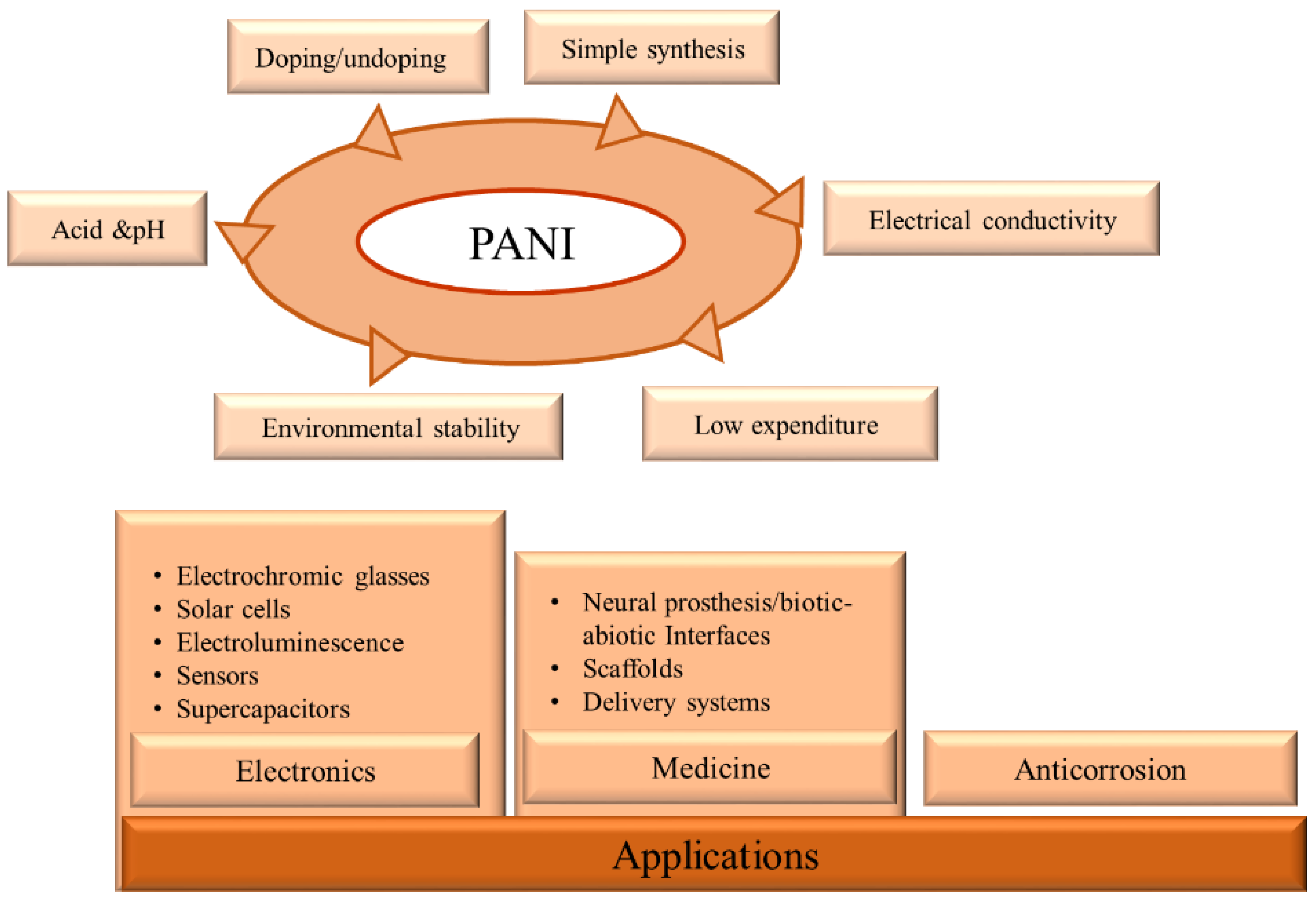
1.2. Advantages of PANI
2. Preparation of PANI
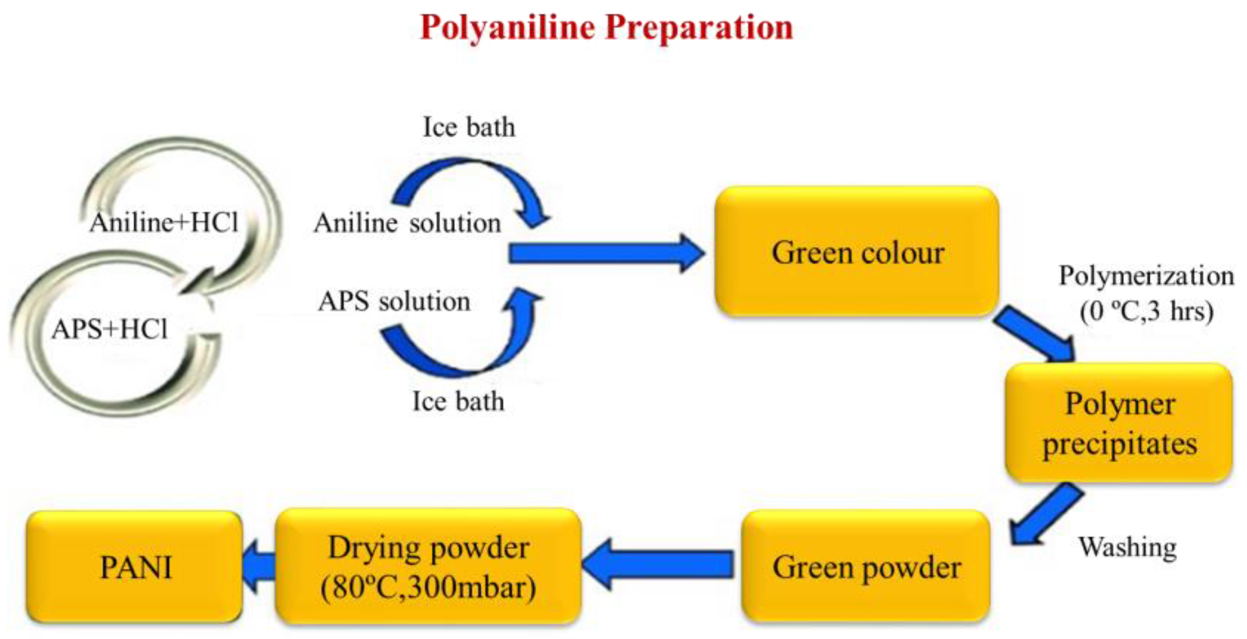
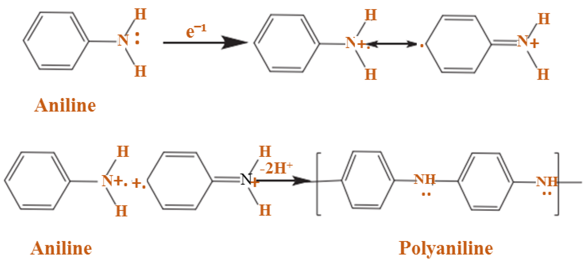
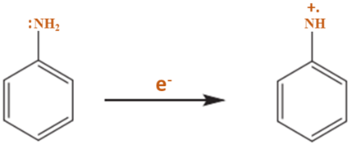
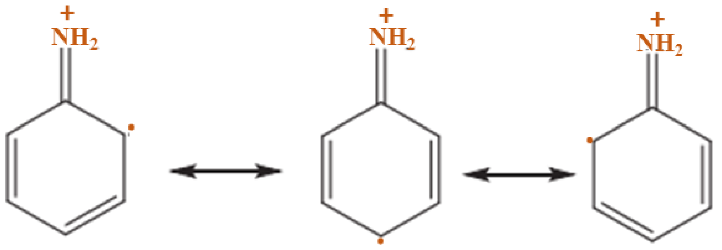
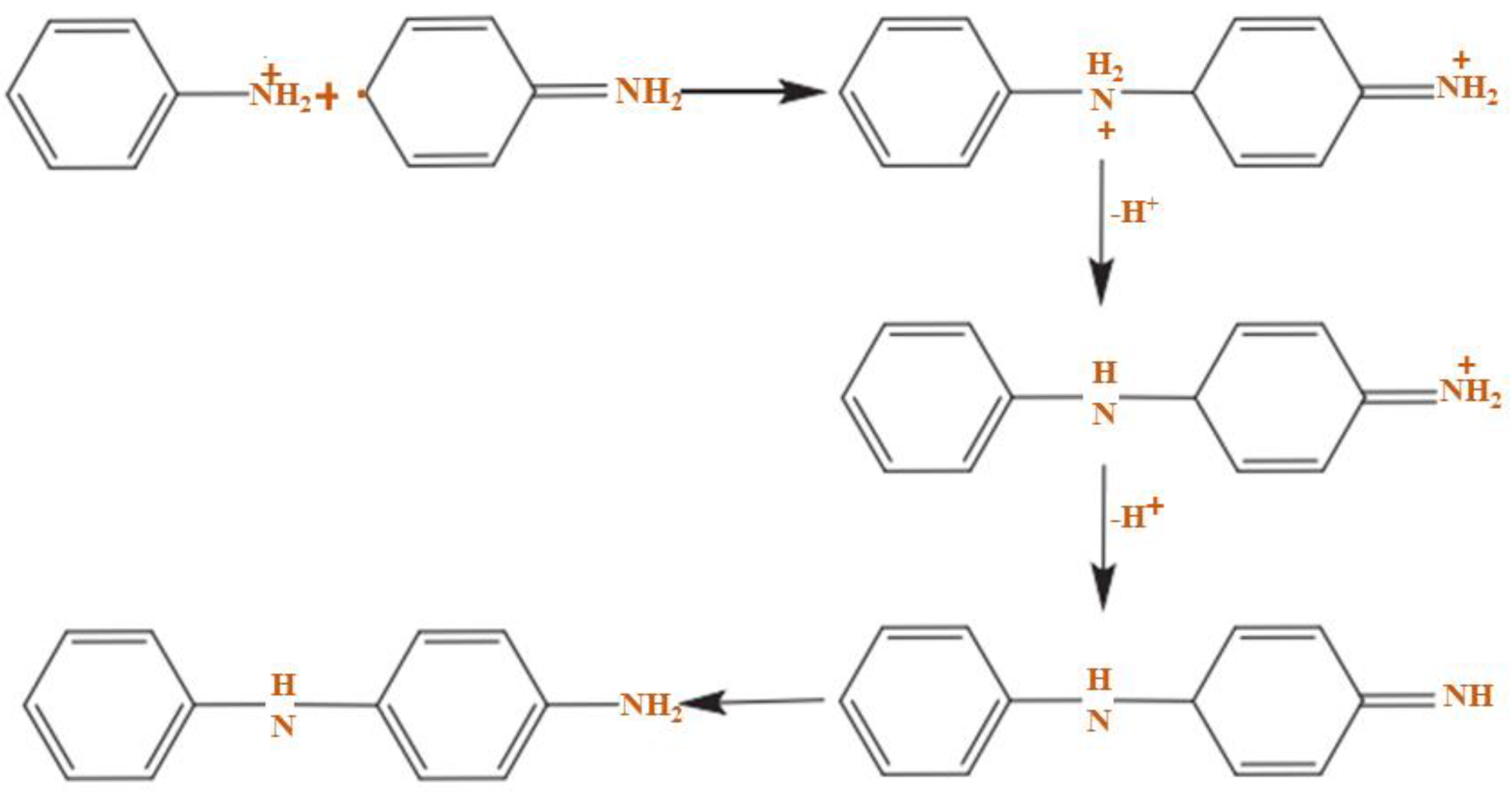
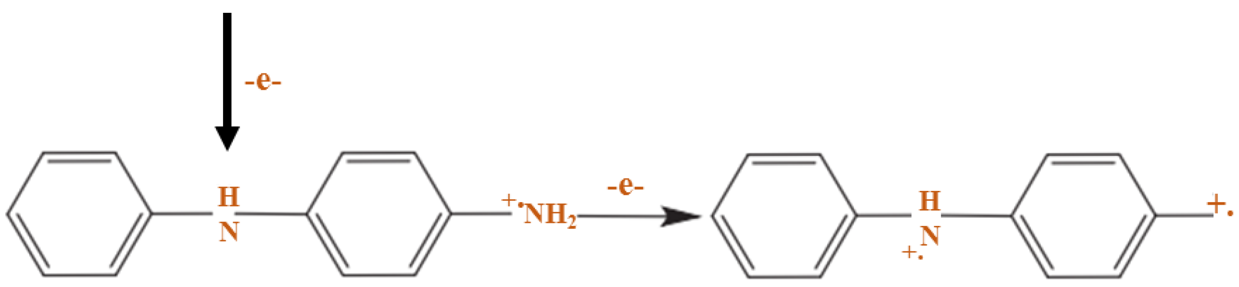
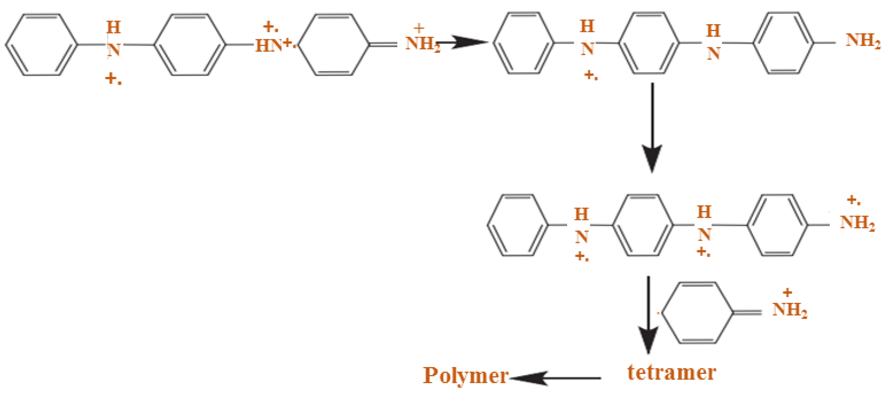
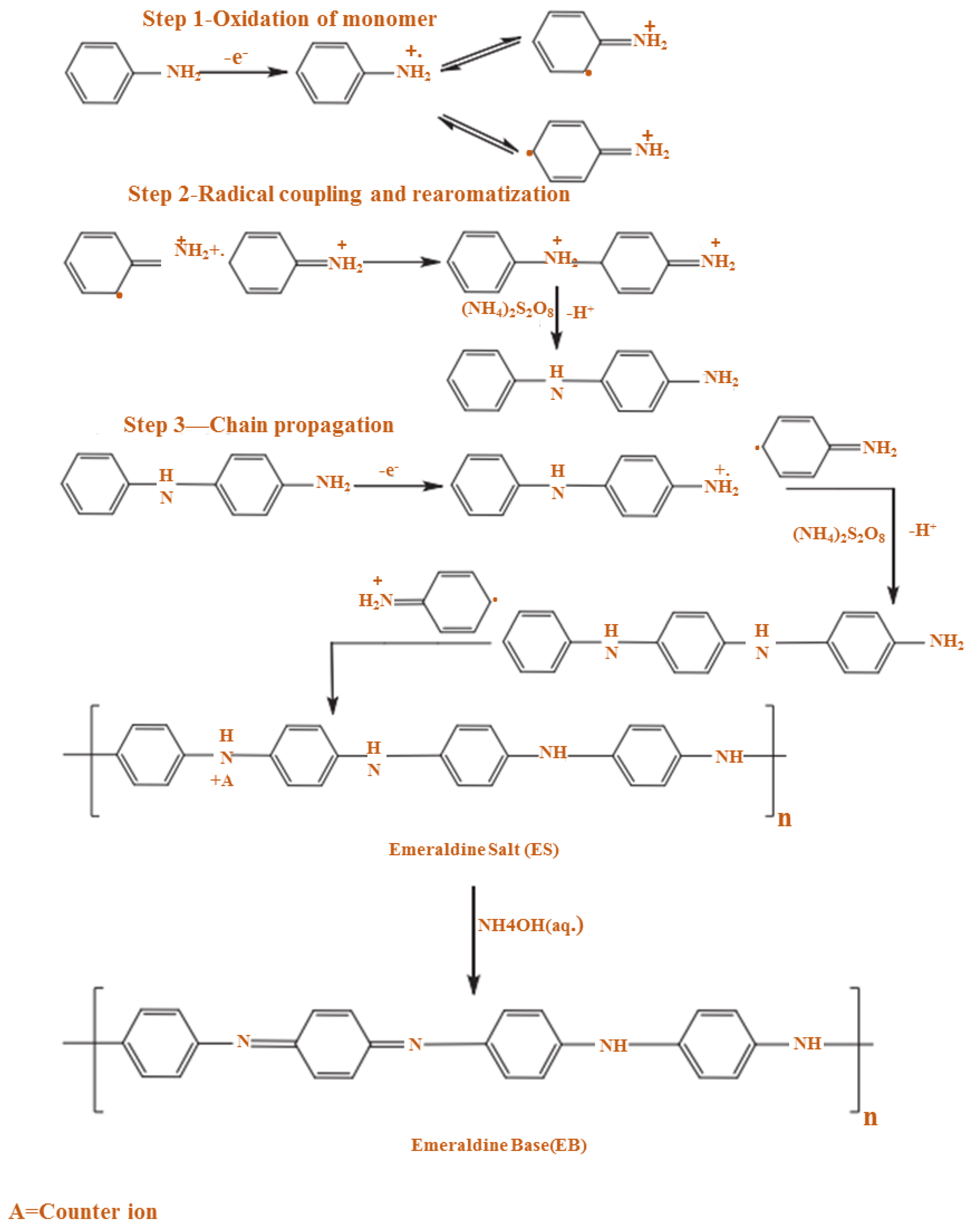
2.1. Chemical Preparation (Oxidative Polymerization)
2.2. Electrochemical Preparation
2.3. Doping of PANI
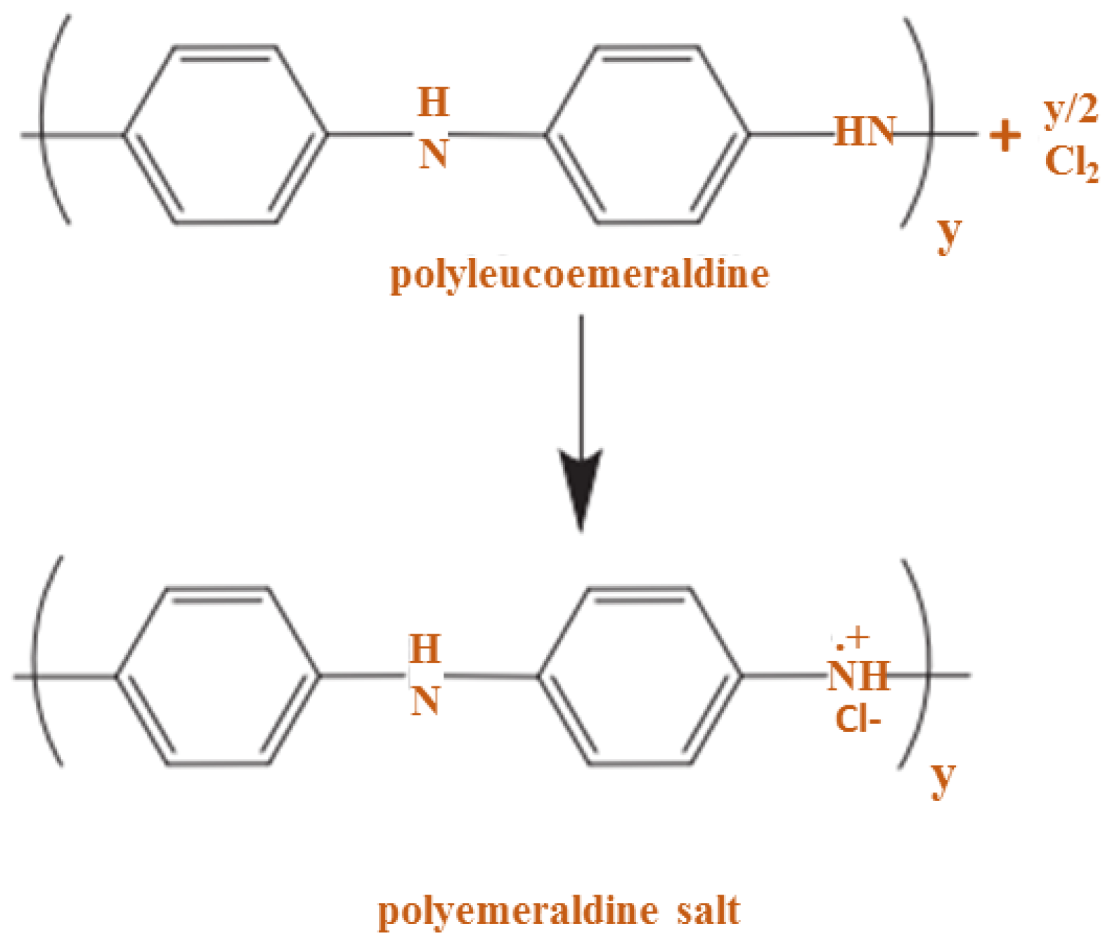
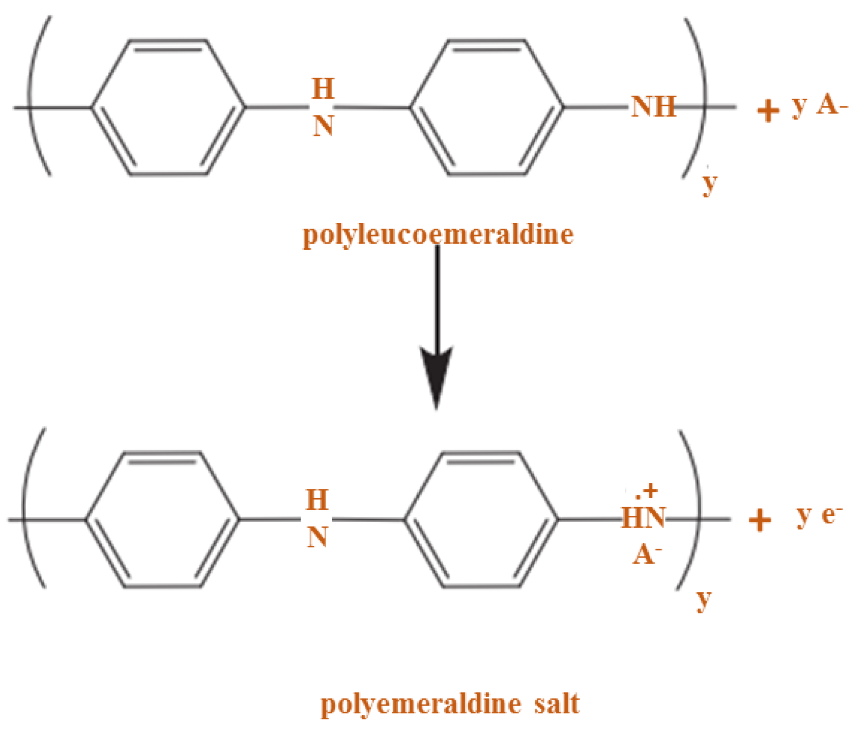
2.4. Oxidative Doping
2.5. Acidic Doping
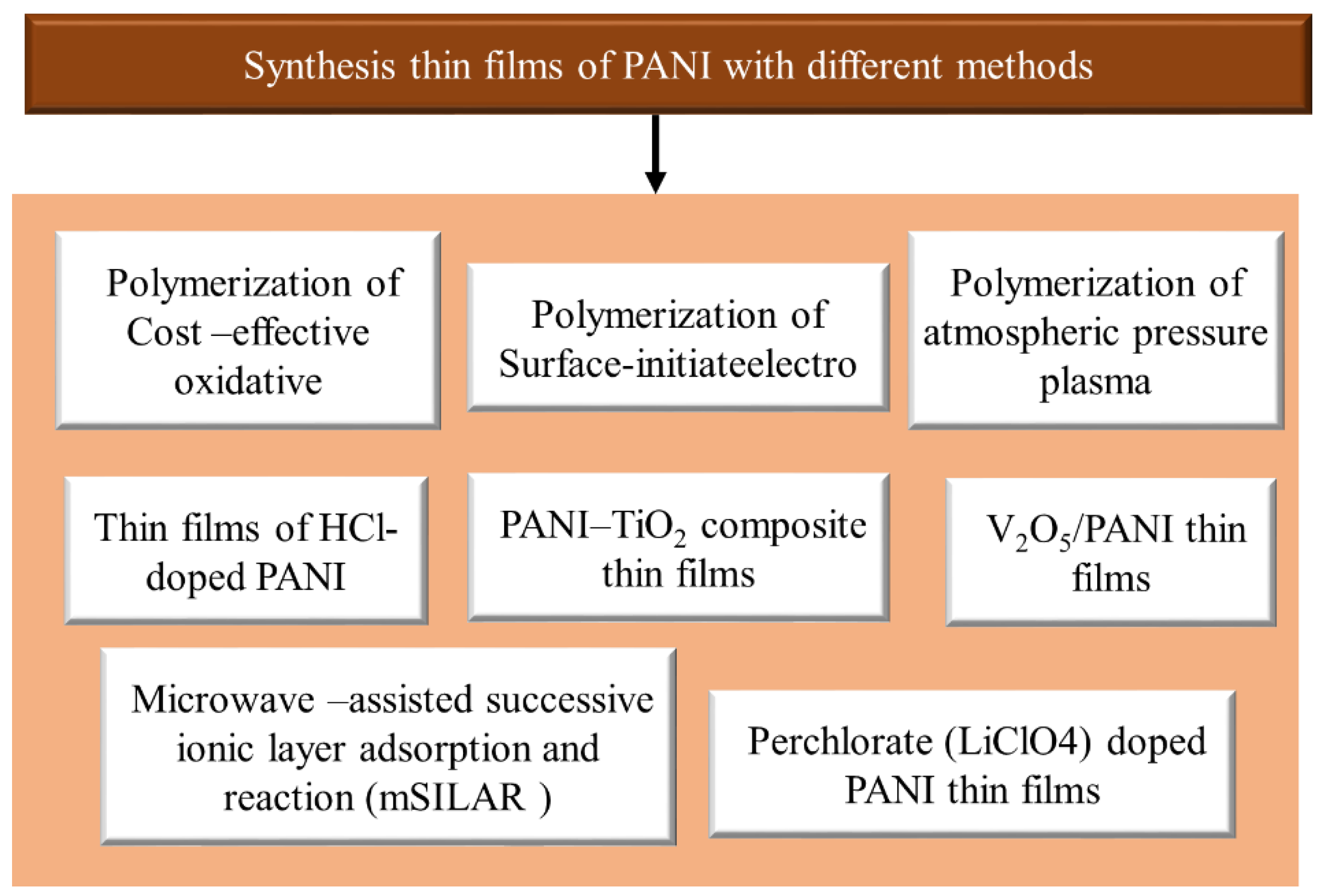
3. Synthesis of Thin Films of PANI with Different Methods
3.1. Cost-Effectiveness of Oxidative Polymerization
3.2. Polymerization of Surface-Initiated Electrons
3.3. Polymerization of Atmospheric Pressure Plasma
3.4. Microwave-Assisted Successive Ionic Layer Adsorption and Reaction (mSILAR)
3.5. PANI–TiO2 Composite Thin Films
3.6. Perchlorate (LiClO4)-Doped PANI Thin Films
3.7. Thin Films of HCl-Doped PANI
3.8. V2O5/PANI Thin Films
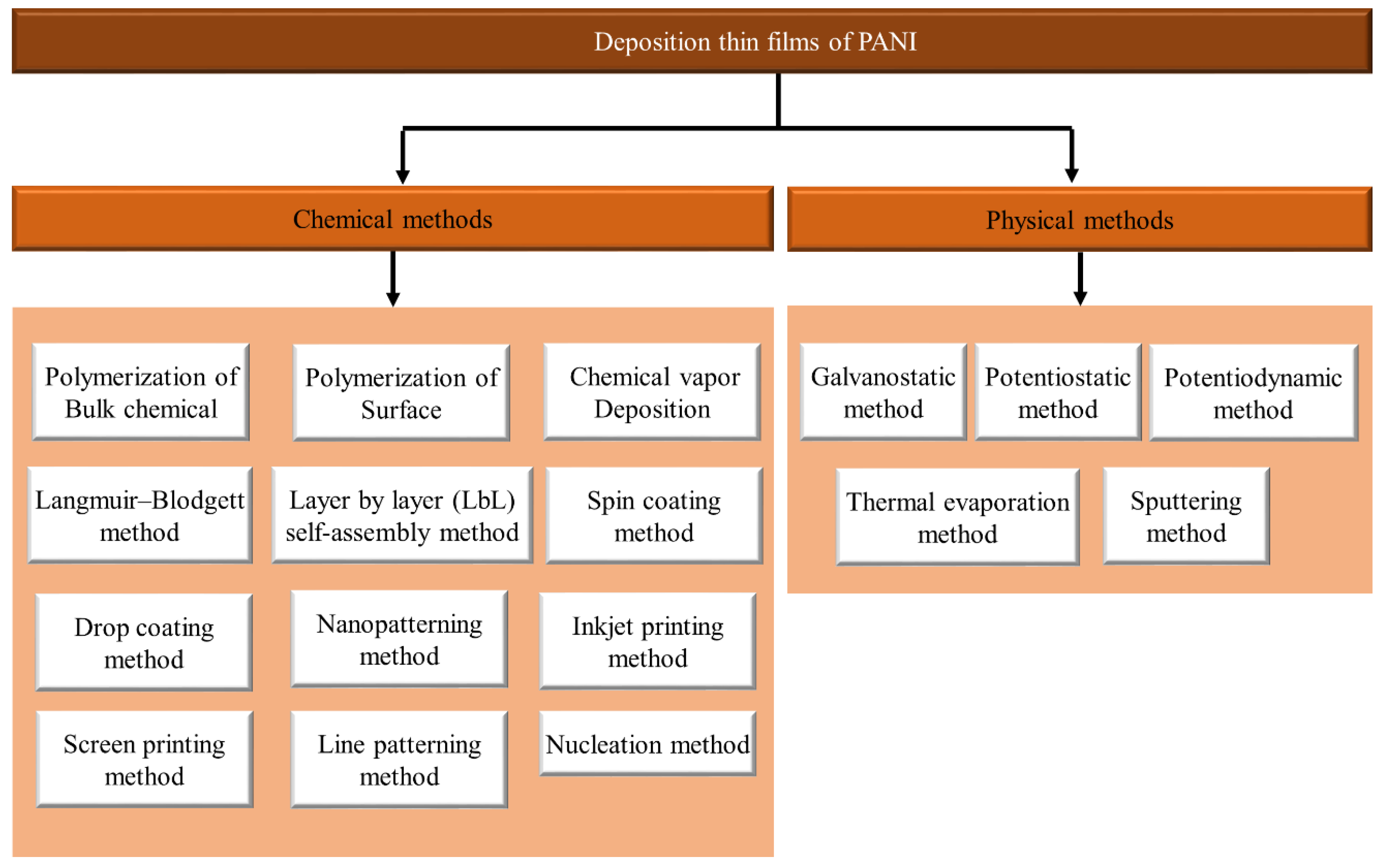
4. Deposition of Thin Films of PANI
4.1. Chemical Techniques
4.1.1. Polymerization of Bulk Chemical
4.1.2. Surface Polymerization
4.1.3. Chemical Vapor Deposition
4.1.4. Langmuir–Blodgett Method
4.1.5. Layer by Layer (LbL) Self-Assembly Method
4.1.6. Spin Coating Method
4.1.7. Drop Coating Method
4.1.8. Nanopatterning Method
4.1.9. Inkjet Printing Method
4.1.10. Screen Printing Method
4.1.11. Line Patterning Method
4.1.12. Nucleation Method
4.2. Physical Methods
- This is an inexpensive way to make thin films.
- Sediment must be selected in a particular area, and the thickness of the deposit will be fully controlled by trying the load.
- This is an extremely useful method of manufacturing thin multilayer materials.
- The deposition will be performed at low temperatures.
- The deposition can be performed in many ways.
- The process will be prepared much easier than competing methods.
- Different types of morphology and compounds will be obtained for polymers, mixtures, and different mixtures (Table 1).
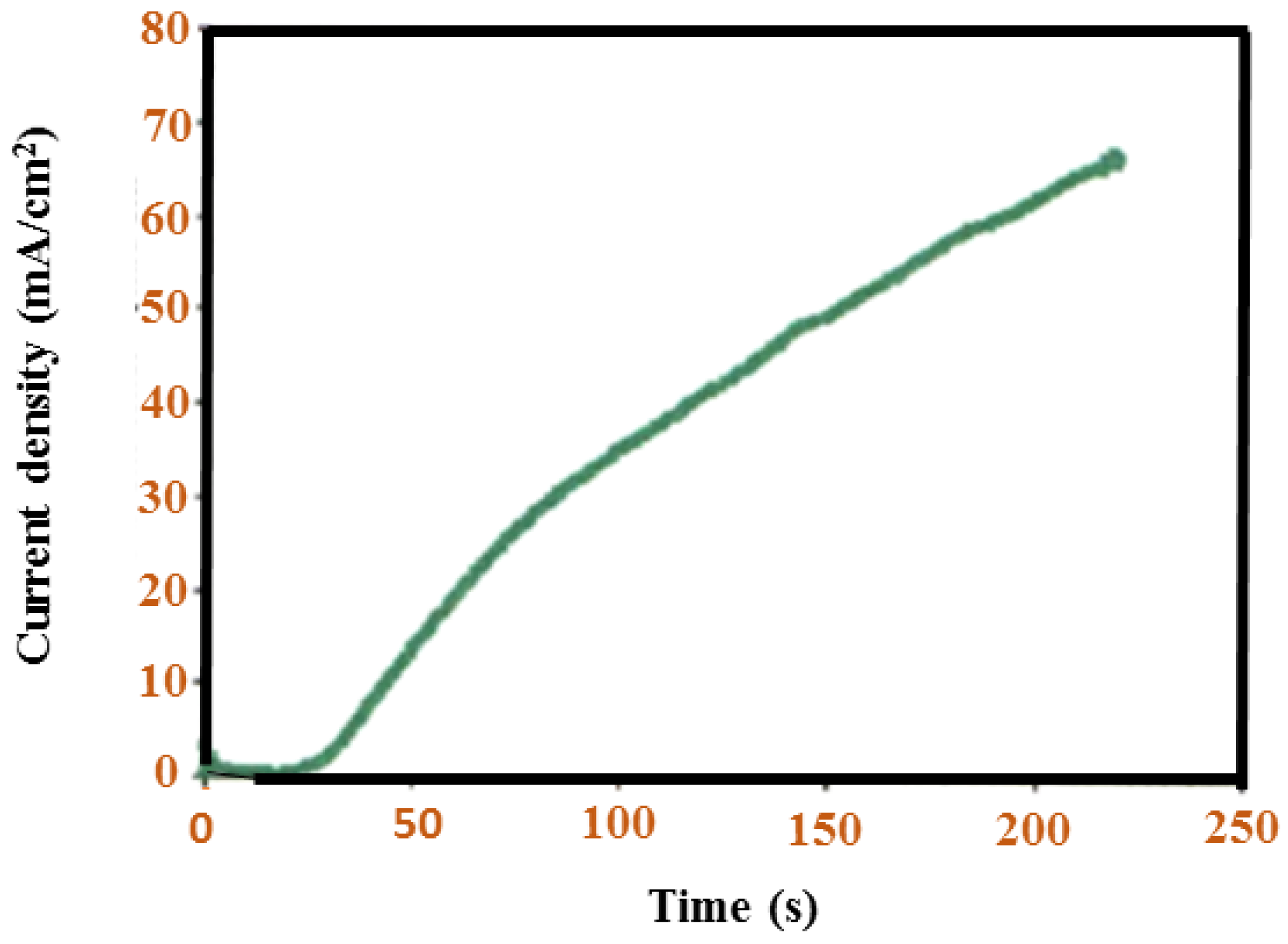
4.2.1. Galvanostatic Method
4.2.2. Potentiostatic Method
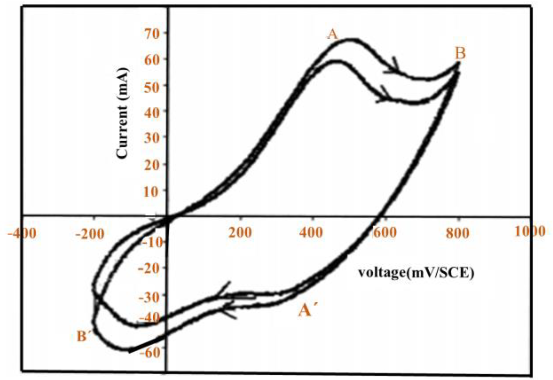
4.2.3. Potentiodynamic Method
4.2.4. Thermal Evaporation
4.2.5. Sputtering Method
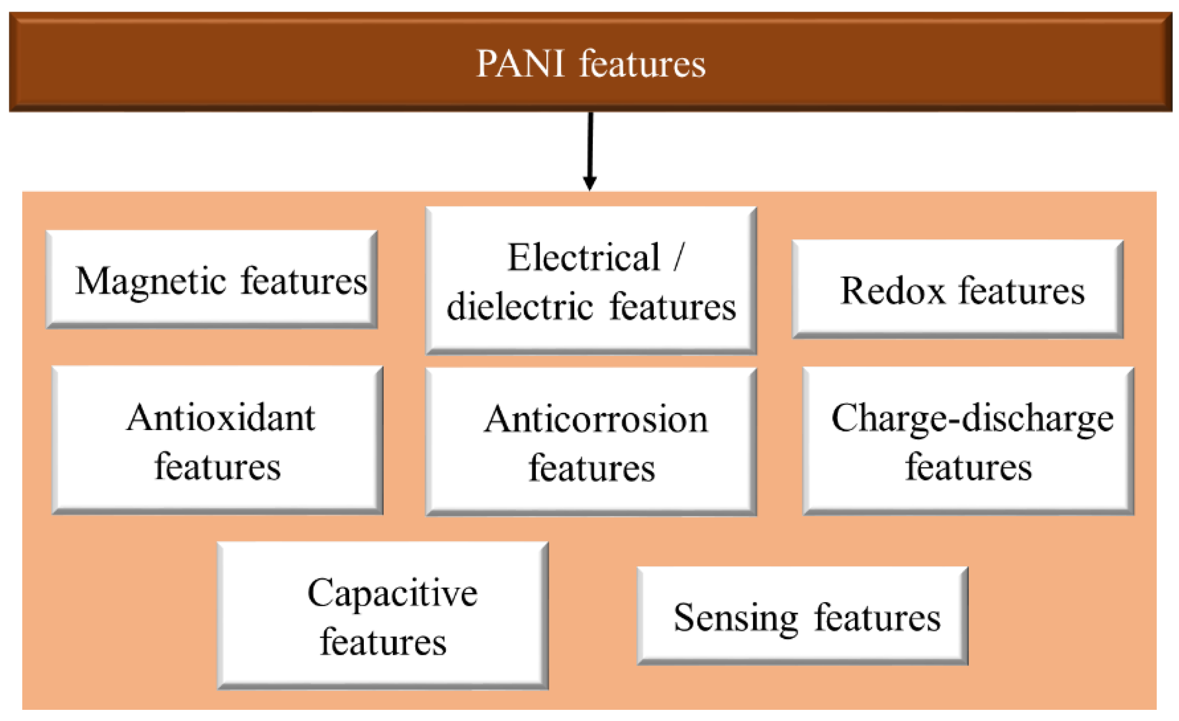
5. PANI Features
5.1. Magnetic Features
5.2. Electrical/Dielectric Features
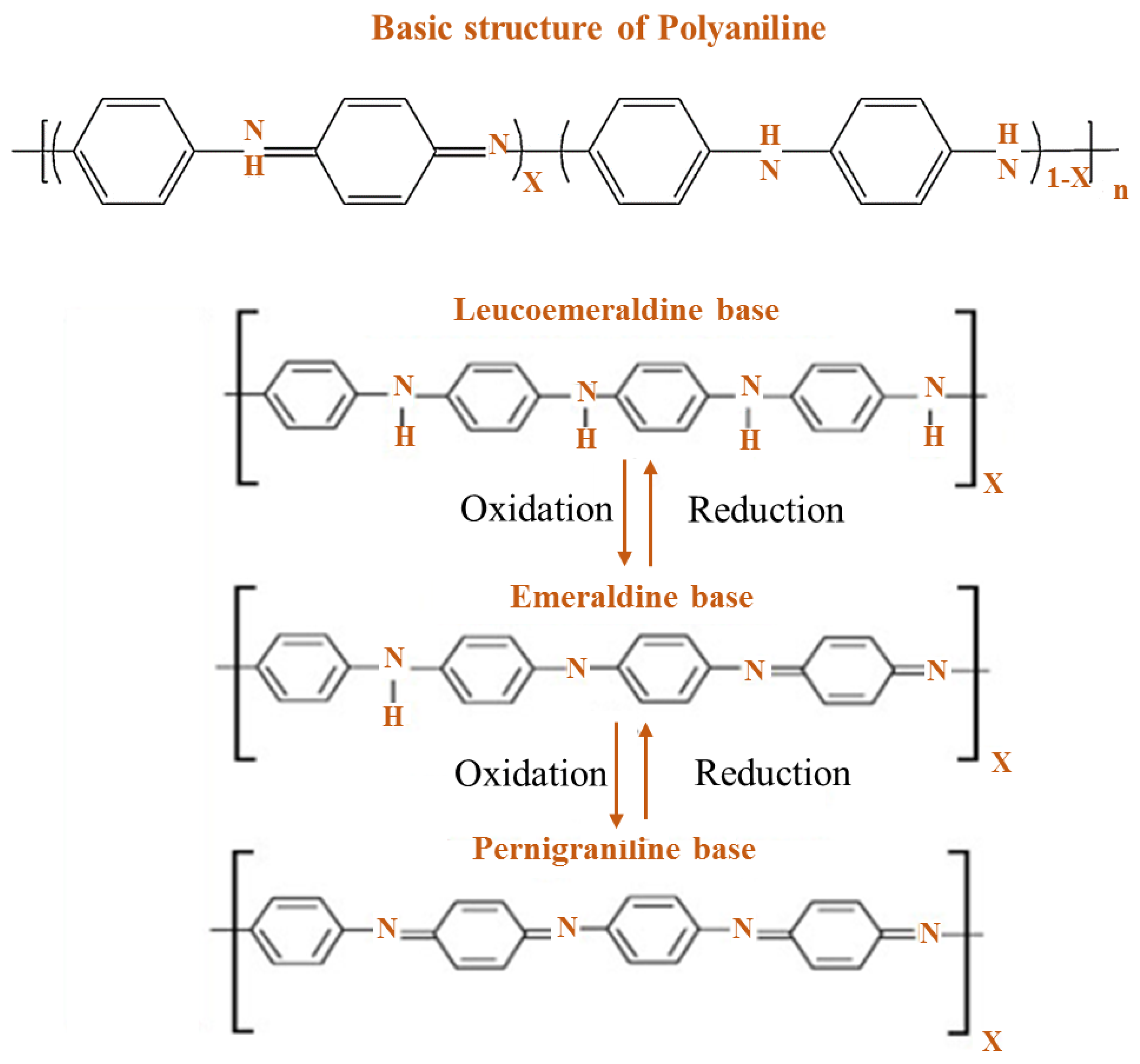
5.3. Redox Features
5.4. Antioxidant Features
5.5. Anti-Corrosion Features
5.6. Charge–Discharge Features
5.7. Capacitive Features
5.8. Sensing Features
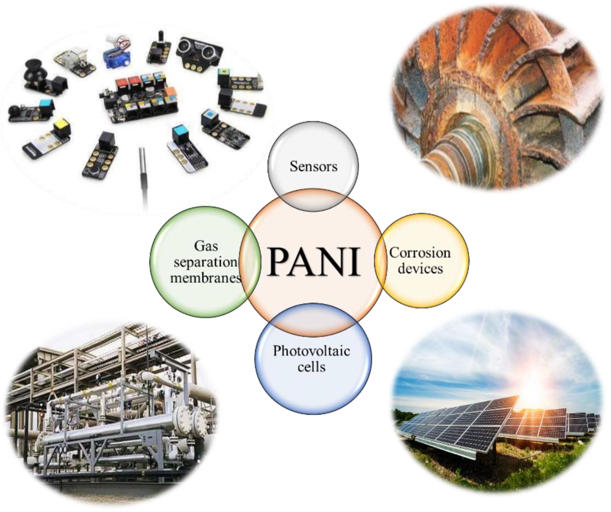
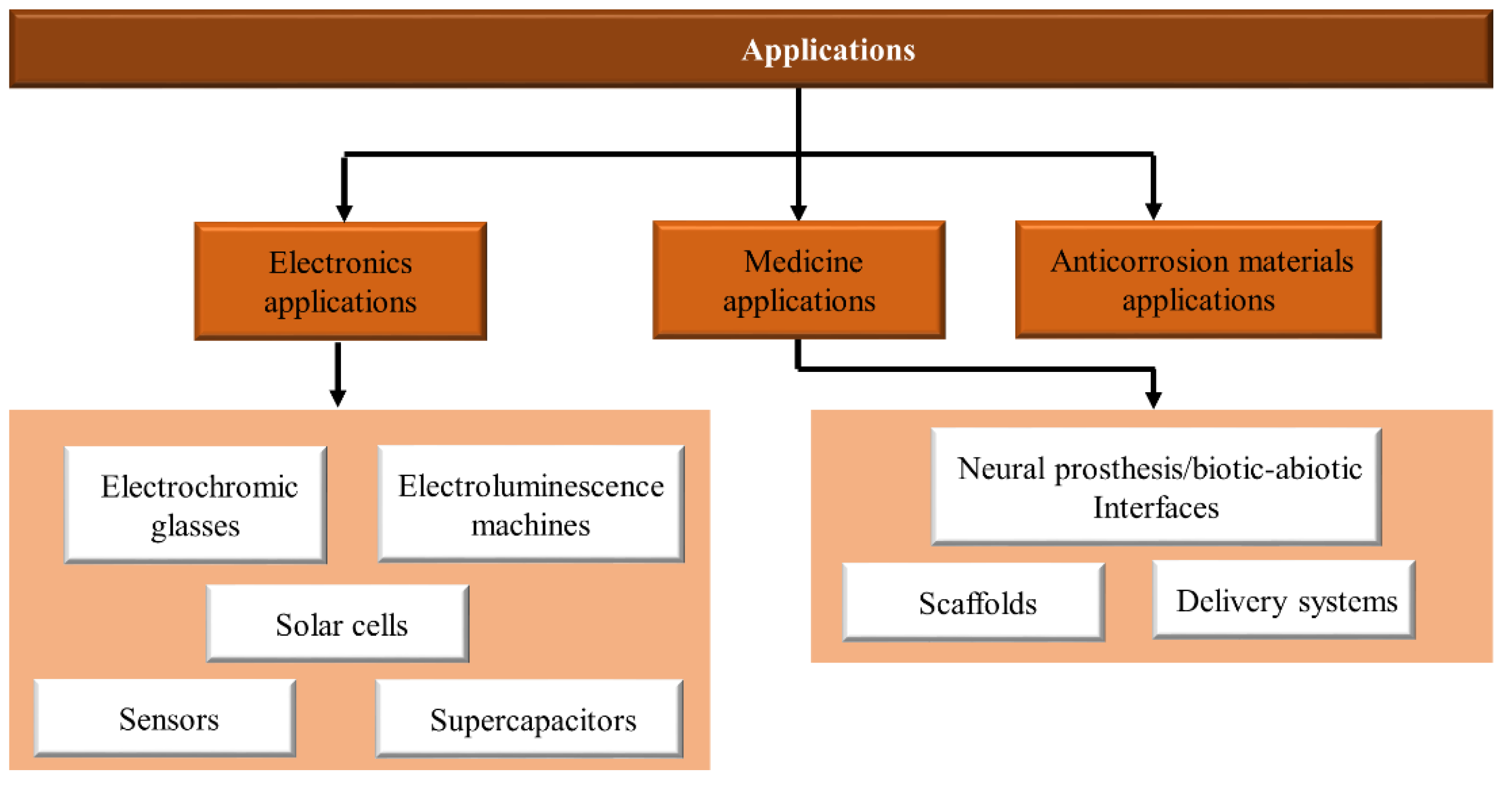
6. PANI Applications
6.1. Electronic Applications
6.1.1. Electrochromic Glasses
6.1.2. Solar Cells
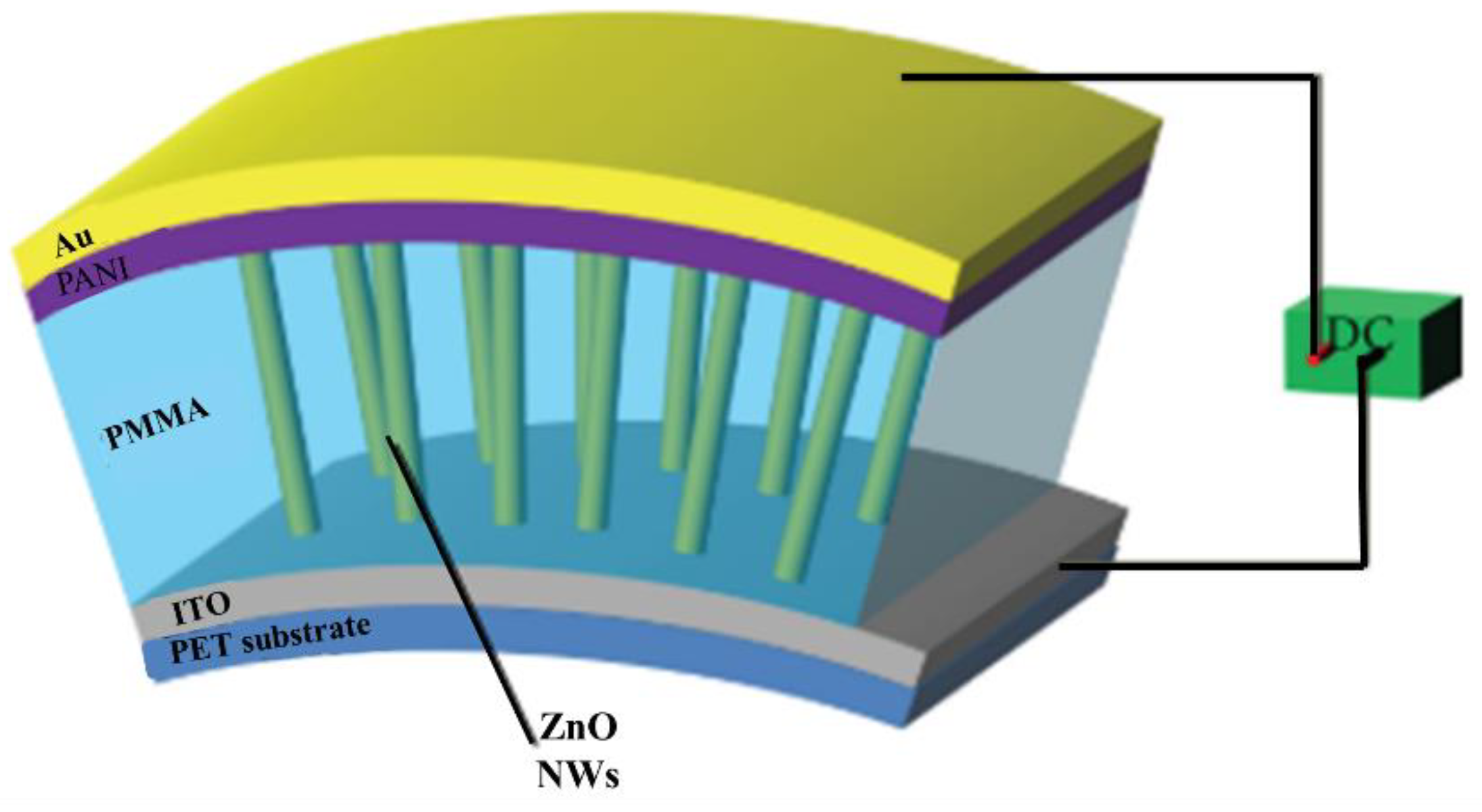
6.1.3. Electroluminescence Machines
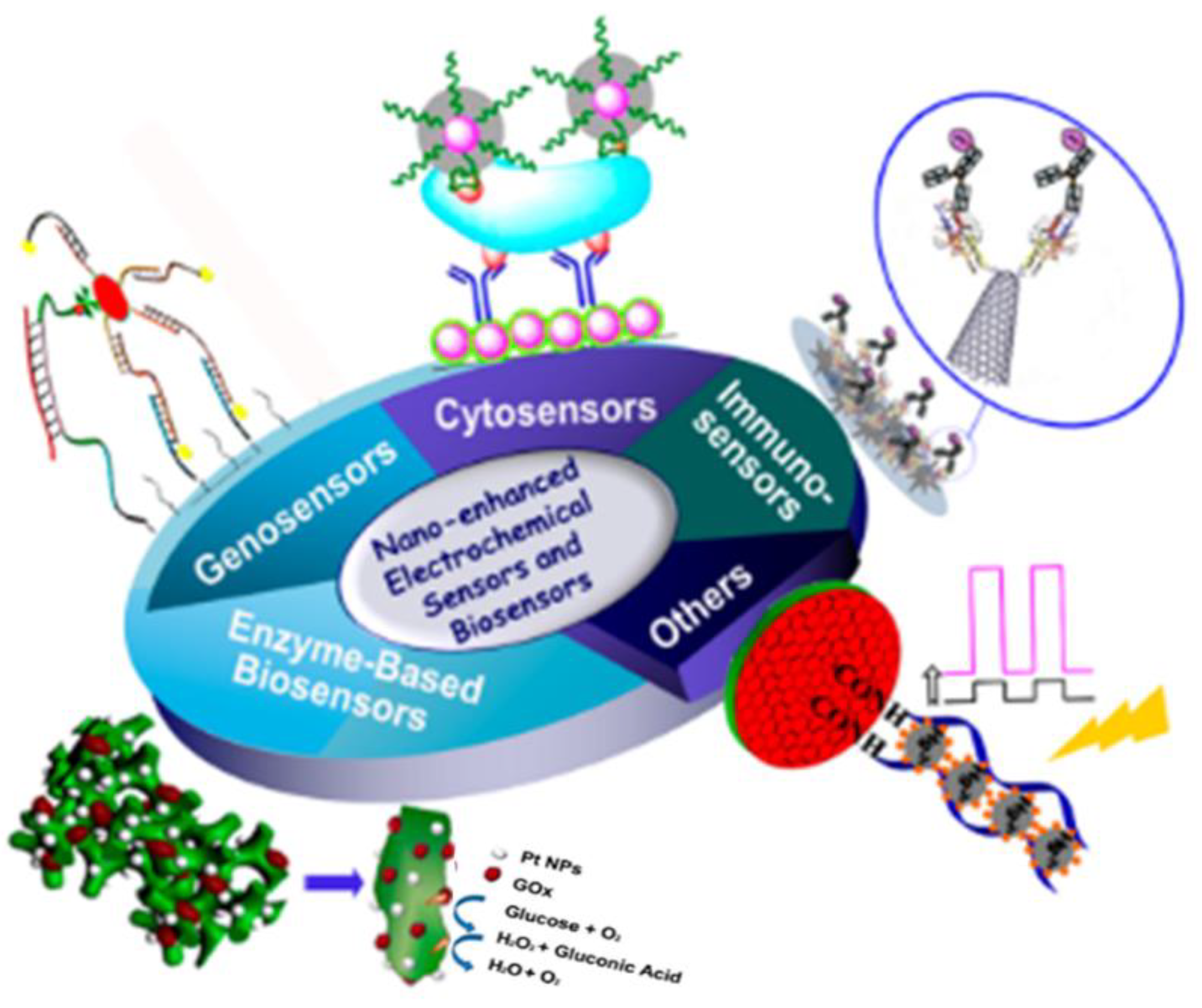
6.1.4. Sensors
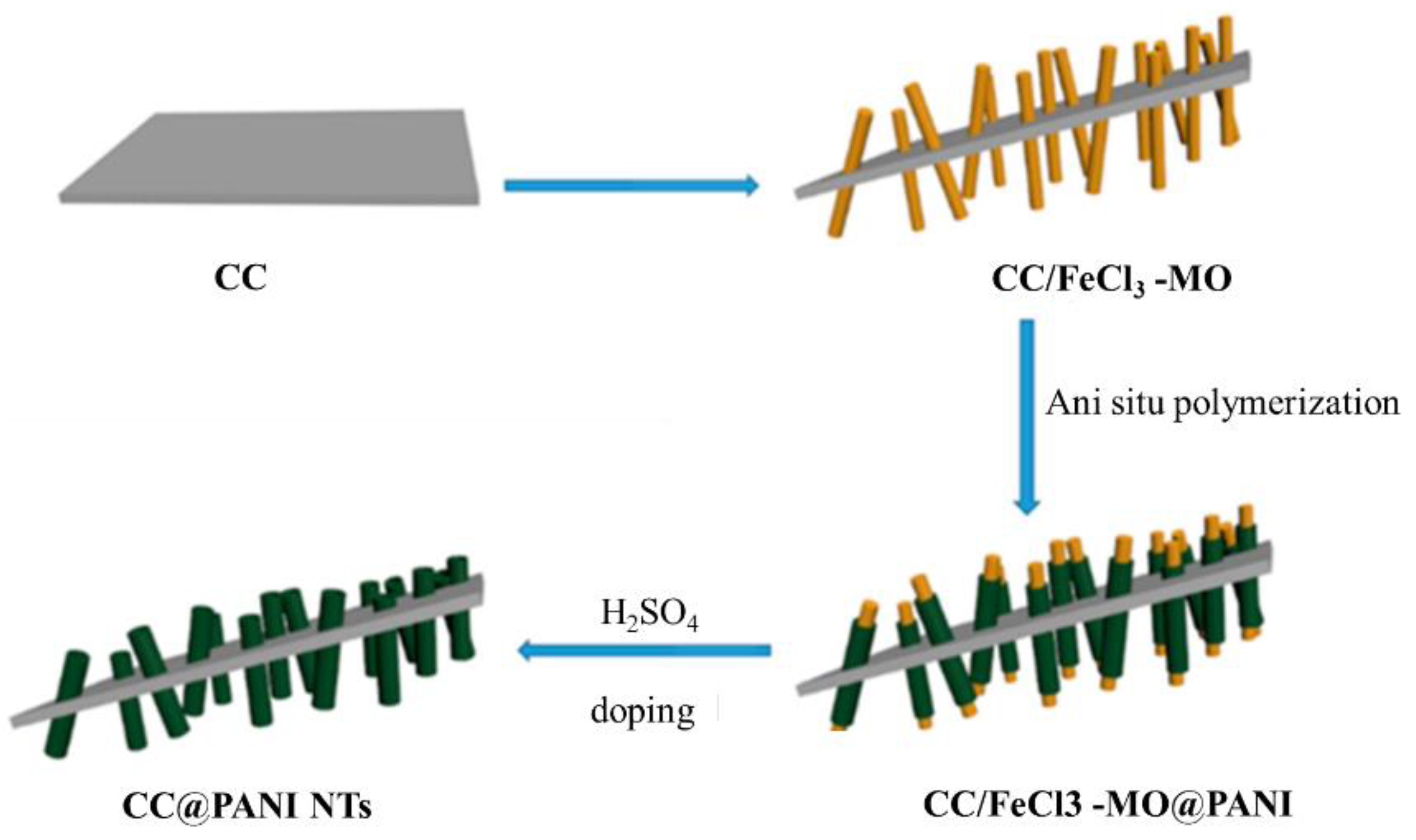
6.1.5. Supercapacitors
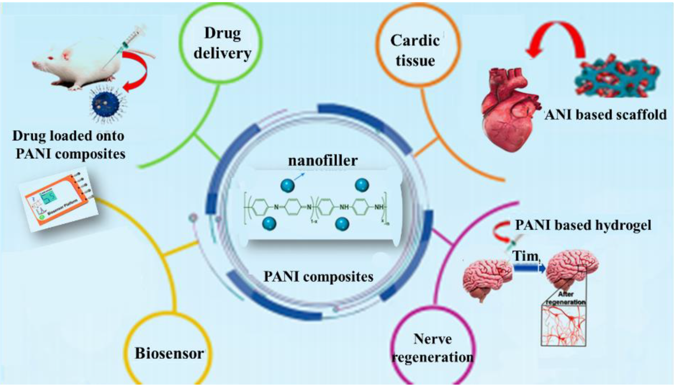
6.2. Medical Applications
6.2.1. Neural Prosthesis/Biotic–Abiotic Interfaces
6.2.2. Scaffolds
6.2.3. Delivery Systems
6.3. Anti-Corrosion Material Applications
7. Conclusions
Author Contributions
Funding
Institutional Review Board Statement
Informed Consent Statement
Data Availability Statement
Acknowledgments
Conflicts of Interest
References
- Najjar, R.; Katourani, S.A.; Hosseini, M.G. Self-healing and corrosion protection performance of organic polysulfide@urea-formaldehyde resin core-shell nanoparticles in epoxy/PANI/ZnO nanocomposite coatings on anodized aluminum alloy. Prog. Org. Coat. 2018, 124, 110–121. [Google Scholar] [CrossRef]
- Du, X.; Zhang, Z.; Liu, W.; Deng, Y. Nanocellulose-based conductive materials and their emerging applications in energy devices—A review. Nano Energy 2017, 35, 299–320. [Google Scholar] [CrossRef]
- Liao, G.; Chen, J.; Zeng, W.; Yu, C.; Yi, C.; Xu, Z. Facile Preparation of Uniform Nanocomposite Spheres with Loading Silver Nanoparticles on Polystyrene-methyl Acrylic Acid Spheres for Catalytic Reduction of 4-Nitrophenol. J. Phys. Chem. C 2016, 120, 25935–25944. [Google Scholar] [CrossRef]
- Liao, G.; Li, Q.; Zhao, W.; Pang, Q.; Gao, H.; Xu, Z. In-situ construction of novel silver nanoparticle decorated polymeric spheres as highly active and stable catalysts for reduction of methylene blue dye. Appl. Catal. A Gen. 2018, 549, 102–111. [Google Scholar] [CrossRef]
- Park, C.; Lee, C.; Kwon, O. Conducting Polymer Based Nanobiosensors. Polymers 2016, 8, 249. [Google Scholar] [CrossRef] [PubMed]
- Bhadra, J.; Alkareem, A.; Al-Thani, N. A review of advances in the preparation and application of polyaniline based thermoset blends and composites. J. Polym. Res. 2020, 27, 122. [Google Scholar] [CrossRef] [Green Version]
- Gómez, I.J.; Sulleiro, M.V.; Mantione, D.; Alegret, N. Carbon nanomaterials embedded in conductive polymers: A state of the art. Polymers 2021, 13, 745. [Google Scholar] [CrossRef] [PubMed]
- Brachetti-Sibaja, S.B.; Palma-Ramírez, D.; Torres-Huerta, A.M.; Domínguez-Crespo, M.A.; Dorantes-Rosales, H.J.; Rodríguez-Salazar, A.E.; Ramírez-Meneses, E. CVD Conditions for MWCNTs Production and Their Effects on the Optical and Electrical Properties of PPy/MWCNTs, PANI/MWCNTs Nanocomposites by In Situ Electropolymerization. Polymers 2021, 13, 351. [Google Scholar] [CrossRef] [PubMed]
- Jaymand, M. Recent progress in chemical modification of polyaniline. Prog. Polym. Sci. 2013, 38, 1287–1306. [Google Scholar] [CrossRef]
- Liao, G. Green Preparation of Sulfonated Polystyrene/Polyaniline/Silver Composites with Enhanced Anticorrosive Properties. Int. J. Chem. 2018, 10, 81. [Google Scholar] [CrossRef] [Green Version]
- Lu, X.; Zhang, W.; Wang, C.; Wen, T.C.; Wei, Y. One-dimensional conducting polymer nanocomposites: Synthesis, properties and applications. Prog. Polym. Sci. 2011, 36, 671–712. [Google Scholar] [CrossRef]
- Baker, C.O.; Huang, X.; Nelson, W.; Kaner, R.B. Polyaniline nanofibers: broadening applications for conducting polymers. Chem. Soc. Rev. 2017, 46, 1510–1525. [Google Scholar] [CrossRef] [PubMed]
- Gao, C.; Chen, G. Conducting polymer/carbon particle thermoelectric composites: Emerging green energy materials. Compos. Sci. Technol. 2016, 124, 52–70. [Google Scholar] [CrossRef]
- Sun, E.; Liao, G.; Zhang, Q.; Qu, P.; Wu, G.; Xu, Y.; Yong, C.; Huang, H. Green Preparation of Straw Fiber Reinforced Hydrolyzed Soy Protein Isolate/Urea/Formaldehyde Composites for Biocomposite Flower Pots Application. Materials 2018, 11, 1695. [Google Scholar] [CrossRef] [PubMed] [Green Version]
- Le Ferrand, H.; Bolisetty, S.; Demirörs, A.F.; Libanori, R.; Studart, A.R.; Mezzenga, R. Magnetic assembly of transparent and conducting graphene-based functional composites. Nat. Commun. 2016, 7, 12078. [Google Scholar] [CrossRef] [PubMed] [Green Version]
- Li, Q.; Liao, G.; Tian, J.; Xu, Z. Preparation of Novel Fluorinated Copolyimide/Amine-Functionalized Sepia Eumelanin Nanocomposites with Enhanced Mechanical, Thermal, and UV-Shielding Properties. Macromol. Mater. Eng. 2018, 303, 1700407. [Google Scholar] [CrossRef]
- Pud, A.; Ogurtsov, N.; Korzhenko, A.; Shapoval, G. Some aspects of preparation methods and properties of polyaniline blends and composites with organic polymers. Prog. Polym. Sci. 2003, 28, 1701–1753. [Google Scholar] [CrossRef]
- Al-Oqla, F.M.; Sapuan, S.M.; Anwer, T.; Jawaid, M.; Hoque, M.E. Natural fiber reinforced conductive polymer composites as functional materials: A review. Synth. Met. 2015, 206, 42–54. [Google Scholar] [CrossRef]
- Pang, H.; Xu, L.; Yan, D.-X.; Li, Z.-M. Conductive polymer composites with segregated structures. Prog. Polym. Sci. 2014, 39, 1908–1933. [Google Scholar] [CrossRef]
- Sobha, A.P.; Sreekala, P.S.; Narayanankutty, S.K. Electrical, thermal, mechanical and electromagnetic interference shielding properties of PANI/FMWCNT/TPU composites. Prog. Org. Coat. 2017, 113, 168–174. [Google Scholar]
- Kenry; Liu, B. Recent advances in biodegradable conducting polymers and their biomedical applications. Biomacromolecules 2018, 19, 1783–1803. [Google Scholar] [CrossRef]
- Chiang, C.K.; Fincher Jr, C.R.; Park, Y.W.; Heeger, A.J.; Shirakawa, H.; Louis, E.J.; Gau, S.C.; MacDiarmid, A.G. Electrical conductivity in doped polyacetylene. Phys. Rev. Lett. 1977, 39, 1098. [Google Scholar] [CrossRef]
- Heeger, A.J.; Kivelson, S.; Schrieffer, J.R.; Su, W.-P. Solitons in conducting polymers. Rev. Mod. Phys. 1988, 60, 781. [Google Scholar] [CrossRef]
- Kumari Jangid, N.; Jadoun, S.; Kaur, N. A review on high-throughput synthesis, deposition of thin films and properties of polyaniline. Eur. Polym. J. 2020, 125, 109485. [Google Scholar] [CrossRef]
- He, Y. Synthesis of polyaniline/nano-CeO2 composite microspheres via a solid-stabilized emulsion route. Mater. Chem. Phys. 2005, 92, 134–137. [Google Scholar] [CrossRef]
- Yadav, G.D. Ultrasonic Approach To Prepare Conductive Polyaniline/Nanocrystalline Titanium Oxide Composites. Chem. Bus. 2002, 16, 14. [Google Scholar]
- Wang, S.; Tan, Z.; Li, Y.; Sun, L.; Zhang, T. Synthesis, characterization and thermal analysis of polyaniline/ZrO2 composites. Thermochim. Acta 2006, 441, 191–194. [Google Scholar] [CrossRef]
- Hsieh, T.-H.; Ho, K.-S.; Huang, C.-H.; Wang, Y.-Z.; Chen, Z.-L. Electromagnetic properties of polyaniline/maghemite nanocomposites: I. The effect of re-doping time on the electromagnetic properties. Synth. Met. 2006, 156, 1355–1361. [Google Scholar] [CrossRef]
- Aphesteguy, J.C.; Jacobo, S.E. Synthesis of a soluble polyaniline–ferrite composite: magnetic and electric properties. J. Mater. Sci. 2007, 42, 7062–7068. [Google Scholar] [CrossRef]
- Prabhakar, P.K.; Raj, S.; Anuradha, P.R.; Sawant, S.N.; Doble, M. Biocompatibility studies on polyaniline and polyaniline–silver nanoparticle coated polyurethane composite. Colloids Surfaces B Biointerfaces 2011, 86, 146–153. [Google Scholar] [CrossRef] [PubMed]
- Zhou, D.D.; Cui, X.T.; Hines, A.; Greenberg, R.J. Conducting polymers in neural stimulation applications. In Implantable Neural Prostheses 2: Techniques and Engineering Approaches; Springer: New York, NY, USA, 2009; pp. 217–252. [Google Scholar]
- Blinova, N.V.; Stejskal, J.; Trchova, M.; Prokeš, J. Control of polyaniline conductivity and contact angles by partial protonation. Polym. Int. 2008, 57, 66–69. [Google Scholar] [CrossRef]
- Liao, G.; Li, Q.; Xu, Z. The chemical modification of polyaniline with enhanced properties: A review. Prog. Org. Coat. 2019, 126, 35–43. [Google Scholar] [CrossRef]
- Sutar, D.S.; Padma, N.; Aswal, D.K.; Deshpande, S.K.; Gupta, S.K.; Yakhmi, J.V. Preparation of nanofibrous polyaniline films and their application as ammonia gas sensor. Sens. Actuators B Chem. 2007, 128, 286–292. [Google Scholar] [CrossRef]
- Stamenov, P.; Madathil, R.; Coey, J.M.D. Dynamic response of ammonia sensors constructed from polyaniline nanofibre films with varying morphology. Sens. Actuators B Chem. 2012, 161, 989–999. [Google Scholar] [CrossRef]
- Schauer, T.; Joos, A.; Dulog, L.; Eisenbach, C.D. Protection of iron against corrosion with polyaniline primers. Prog. Org. Coat. 1998, 33, 20–27. [Google Scholar] [CrossRef]
- Bejbouji, H.; Vignau, L.; Miane, J.L.; Dang, M.-T.; Oualim, E.M.; Harmouchi, M.; Mouhsen, A. Polyaniline as a hole injection layer on organic photovoltaic cells. Sol. Energy Mater. Sol. Cells 2010, 94, 176–181. [Google Scholar] [CrossRef]
- Illing, G.; Hellgardt, K.; Wakeman, R.J.; Jungbauer, A. Preparation and characterisation of polyaniline based membranes for gas separation. J. Membr. Sci. 2001, 184, 69–78. [Google Scholar] [CrossRef]
- Wang, Y.; Chen, J.; Shen, Y.; Wang, T.; Ni, Y.; Zhang, Z.; Sun, L.; Ji, B.; Wang, B. Control of Conductive and Mechanical Performances of Poly(Amide-Imide) Composite Films Utilizing Synergistic Effect of Polyaniline and Multi-Walled Carbon Nanotube. Polym. Eng. Sci. 2019, 59, E224–E230. [Google Scholar] [CrossRef]
- Saini, P.; Choudhary, V.; Singh, B.P.; Mathur, R.B.; Dhawan, S.K. Polyaniline–MWCNT nanocomposites for microwave absorption and EMI shielding. Mater. Chem. Phys. 2009, 113, 919–926. [Google Scholar] [CrossRef]
- Shirakawa, H.; Louis, E.J.; MacDiarmid, A.G.; Chiang, C.K.; Heeger, A.J. Synthesis of electrically conducting organic polymers: Halogen derivatives of polyacetylene, (CH)x. J. Chem. Soc. Chem. Commun. 1977, 578–580. [Google Scholar] [CrossRef]
- Wang, H.; Wen, H.; Hu, B.; Fei, G.; Shen, Y.; Sun, L.; Yang, D. Facile approach to fabricate waterborne polyaniline nanocomposites with environmental benignity and high physical properties. Sci. Rep. 2017, 7, 43694. [Google Scholar] [CrossRef] [PubMed] [Green Version]
- Liao, G.; Gong, Y.; Yi, C.; Xu, Z. Soluble, Antibaterial, and Anticorrosion Studies of Sulfonated Polystyrene/Polyaniline/Silver Nanocomposites Prepared with the Sulfonated Polystyrene Template. Chin. J. Chem. 2017, 35, 1157–1164. [Google Scholar] [CrossRef]
- Ma, Z.; Kan, J. Study of cylindrical Zn/PANI secondary batteries with the electrolyte containing alkylimidazolium ionic liquid. Synth. Met. 2013, 174, 58–62. [Google Scholar] [CrossRef]
- Marins, J.A.; Soares, B.G.; Fraga, M.; Müller, D.; Barra, G.M.O. Self-supported bacterial cellulose polyaniline conducting membrane as electromagnetic interference shielding material: effect of the oxidizing agent. Cellulose 2014, 21, 1409–1418. [Google Scholar] [CrossRef]
- Gizzie, E.A.; Scott Niezgoda, J.; Robinson, M.T.; Harris, A.G.; Kane Jennings, G.; Rosenthal, S.J.; Cliffel, D.E. Photosystem I-polyaniline/TiO 2 solid-state solar cells: Simple devices for biohybrid solar energy conversion. Energy Environ. Sci. 2015, 8, 3572–3576. [Google Scholar] [CrossRef]
- Pérez-Mitta, G.; Albesa, A.G.; Trautmann, C.; Toimil-Molares, M.E.; Azzaroni, O. Bioinspired integrated nanosystems based on solid-state nanopores: “iontronic” transduction of biological, chemical and physical stimuli. Chem. Sci. 2017, 8, 890–913. [Google Scholar] [CrossRef] [PubMed] [Green Version]
- Ramezanzadeh, B.; Bahlakeh, G.; Ramezanzadeh, M. Polyaniline-cerium oxide (PAni-CeO2) coated graphene oxide for enhancement of epoxy coating corrosion protection performance on mild steel. Corros. Sci. 2018, 137, 111–126. [Google Scholar] [CrossRef]
- Xu, R.-P.; Li, Y.-Q.; Tang, J.-X. Recent advances in flexible organic light-emitting diodes. J. Mater. Chem. C 2016, 4, 9116–9142. [Google Scholar] [CrossRef]
- Tang, J.; Wen, X.; Liu, Z.; Wang, J.; Zhang, P. Synthesis and electrorheological performances of 2D PANI/TiO2 nanosheets. Colloids Surfaces A Physicochem. Eng. Asp. 2018, 552, 24–31. [Google Scholar] [CrossRef]
- Gospodinova, N.; Terlemezyan, L. Conducting polymers prepared by oxidative polymerization: Polyaniline. Prog. Polym. Sci. 1998, 23, 1443–1484. [Google Scholar] [CrossRef]
- Press, D. Polyaniline-based biosensors. Nanobiosens. Dis. Diagn. 2015, 4, 25–46. [Google Scholar]
- MacDiarmid, A.G. Polyaniline and polypyrrole: Where are we headed? Synth. Met. 1997, 84, 27–34. [Google Scholar] [CrossRef]
- Venugopal, G.; Quan, X.; Johnson, G.E.; Houlihan, F.M.; Chin, E.; Nalamasu, O. Photoinduced Doping and Photolithography of Methyl-Substituted Polyaniline. Chem. Mater. 1995, 7, 271–276. [Google Scholar] [CrossRef]
- Malinauskas, A. Self-doped polyanilines. J. Power Sources 2004, 126, 214–220. [Google Scholar] [CrossRef]
- Bhadra, S.; Singha, N.K.; Khastgir, D. Dual functionality of PTSA as electrolyte and dopant in the electrochemical synthesis of polyaniline, and its effect on electrical properties. Polym. Int. 2007, 56, 919–927. [Google Scholar] [CrossRef]
- Lodermeyer, F.; Prato, M.; Costa, R.D.; Guldi, D.M. Facile and quick preparation of carbon nanohorn-based counter electrodes for efficient dye-sensitized solar cells. Nanoscale 2016, 8, 7556–7561. [Google Scholar] [CrossRef] [PubMed] [Green Version]
- Arakawa, C.K.; Deforest, C.A. Polymer Design and Development; Elsevier Inc.: Amsterdam, The Netherlands, 2017; ISBN 9780128027349. [Google Scholar]
- Ridge, K. Polyaniline: A polymer with many interesting intrinsic redox states. Prog. Polym. Sci. 1998, 23, 277–324. [Google Scholar]
- Long, Y.; Li, M.; Gu, C.; Wan, M.; Duvail, J.; Liu, Z.; Fan, Z. Progress in Polymer Science Recent advances in synthesis, physical properties and applications of conducting polymer nanotubes and nanofibers. Prog. Polym. Sci. 2011, 36, 1415–1442. [Google Scholar] [CrossRef]
- Stejskal, J.; Sapurina, I.; Prokeš, J.; Zemek, J. In-situ polymerized polyaniline films. Synth. Met. 1999, 105, 195–202. [Google Scholar] [CrossRef]
- Fayzan, M.; Nawaz, A.; Khan, R.; Javed, S.; Tariq, A.; Azeem, M.; Riaz, A.; Shafqat, A.; Cheema, H.M.; Aftab, M.; et al. Results in Physics EMI shielding properties of polymer blends with inclusion of graphene nano platelets. Results Phys. 2019, 14, 102365. [Google Scholar] [CrossRef]
- Ćirić-Marjanović, G. Recent advances in polyaniline research: Polymerization mechanisms, structural aspects, properties and applications. Synth. Met. 2013, 177, 1–47. [Google Scholar] [CrossRef]
- Tan, S.; Zhai, J.; Xue, B.; Wan, M.; Meng, Q.; Li, Y.; Jiang, L.; Zhu, D. Property Influence of Polyanilines on Photovoltaic Behaviors of Dye-Sensitized Solar Cells. Langmuir 2004, 20, 2934–2937. [Google Scholar] [CrossRef]
- Geethalakshmi, D.; Muthukumarasamy, N.; Balasundaraprabhu, R. Measurement on the structural, morphological, electrical and optical properties of PANI-CSA nanofilms. Measurement 2016, 92, 446–452. [Google Scholar] [CrossRef]
- Aldissi, M. Intrinsically Conducting Polymers: An Emerging Technology; Springer Science & Business Media: Berlin, Germany, 2013; Volume 246, ISBN 9401719527. [Google Scholar]
- Borole, D.D.; Kapadi, U.R.; Mahulikar, P.P.; Hundiwale, D.G. Synthesis and characterization of conducting homopolymers and copolymers of o-anisidine and o-toluidine in inorganic and organic supporting electrolytes. J. Appl. Polym. Sci. 2003, 90, 2634–2642. [Google Scholar] [CrossRef]
- Koval, E.P.; Whittingham, S.; Skolozdra, O.M.; Zavalij, P.Y.; Zavaliy, I.Y.; Reshetnyak, O.V.; Seledets, M. Co-polymers of aniline and nitroanilines. Part I. Mechanism of aniline oxidation polycondensation. Mater. Chem. Phys. 2001, 69, 154–162. [Google Scholar]
- Genies, E.M.; Lapkowski, M. Spectroelectrochemical evidence for an intermediate in the electropolymerization of aniline. J. Electroanal. Chem. 1987, 236, 189–197. [Google Scholar] [CrossRef]
- Khalid, M.; Honorato, A.M.B.; Varela, H. Polyaniline: Synthesis Methods, Doping and Conduction Mechanism; IntechOpen: London, UK, 2018. [Google Scholar]
- Heeger, A.J. Semiconducting and Metallic Polymers: The Fourth Generation of Polymeric Materials. J. Phys. Chem. B 2001, 105, 8475–8491. [Google Scholar] [CrossRef]
- Wan, M. Conducting Polymers with Micro or Nanometer Structure; Springer: Berlin/Heidelberg, Germany, 2008; ISBN 354069322X. [Google Scholar]
- Abbas, Z.K. Intrinsically Conducting Polyaniline Blends. Ph.D. Thesis, Kingston University, London, UK, 2009. [Google Scholar]
- Toshima, N.; Yan, H. Chemical preparation of polyaniline and its derivatives by using cerium (IV) sulfate. Novel preparation of polyxylidines. Bull. Chem. Soc. Jpn. 1995, 68, 1056–1063. [Google Scholar] [CrossRef]
- Fisal Alesary, H.; Khalil Ismail, H.; Fadhil Khudhair, A.; Qasim Mohammed, M. Effects of Dopant Ions on the Properties of Polyaniline Conducting Polymer. Orient. J. Chem. 2018, 34, 2525–2533. [Google Scholar] [CrossRef] [Green Version]
- Ban, Â.G.; Saniger, Â.M.; Hu, H. Thin ® lms of polyaniline ± polyacrylic acid composite by chemical bath deposition. Thin Solid Films 1999, 347, 241–247. [Google Scholar]
- Athawale, A.A.; Kulkarni, M.V.; Chabukswar, V.V. Studies on chemically synthesized soluble acrylic acid doped polyaniline. Mater. Chem. Phys. 2002, 73, 106–110. [Google Scholar] [CrossRef]
- Hui, J.; Wei, D.; Chen, J.; Yang, Z. Polyaniline nanotubes/carbon cloth composite electrode by thermal acid doping for high-performance supercapacitors. Polymers 2019, 11, 2053. [Google Scholar] [CrossRef] [PubMed] [Green Version]
- Chauhan, N.P.S.; Jangid, N.K.; Punjabi, P.B. Synthesis and Characterization of Conducting Polyanilines via Catalytic Oxidative Polymerization. Int. J. Polym. Mater. 2013, 62, 550–555. [Google Scholar] [CrossRef]
- DIXIT, V. Carbon monoxide sensitivity of vacuum deposited polyaniline semiconducting thin films. Sens. Actuators B Chem. 2005, 104, 90–93. [Google Scholar] [CrossRef]
- Elizalde-Torres, J.; Hu, H.; Saniger, J.M. Comparison of NO2 and NH3 gas adsorption on semiconductor poly aniline thin films. Rev. Mex. Fis. 2005, 51, 482–487. [Google Scholar]
- Deshpande, N.G.; Gudage, Y.G.; Vyas, J.C.; Singh, F.; Sharma, R. Studies on the high electronic energy deposition in polyaniline thin films. Nucl. Instrum. Methods Phys. Res. Sect. B Beam Interact. Mater. Atoms 2008, 266, 2002–2008. [Google Scholar] [CrossRef]
- Birajadar, R.B.; Upadhye, D.; Mahajan, S.; Vyas, J.C.; Sharma, R. Study of room temperature LPG sensing behavior of polyaniline thin film synthesized by cost effective oxidative polymerization technique. J. Mater. Sci. Mater. Electron. 2015, 26, 5065–5070. [Google Scholar] [CrossRef]
- Blacha-Grzechnik, A.; Turczyn, R.; Burek, M.; Zak, J. In situ Raman spectroscopic studies on potential-induced structural changes in polyaniline thin films synthesized via surface-initiated electropolymerization on covalently modified gold surface. Vib. Spectrosc. 2014, 71, 30–36. [Google Scholar] [CrossRef]
- Park, C.-S.; Kim, D.H.; Shin, B.J.; Tae, H.-S. Synthesis and characterization of nanofibrous polyaniline thin film prepared by novel atmospheric pressure plasma polymerization technique. Materials 2016, 9, 39. [Google Scholar] [CrossRef] [Green Version]
- Kim, J.Y.; Iqbal, S.; Jang, H.J.; Jung, E.Y.; Bae, G.T.; Park, C.S.; Tae, H.S. In-situ iodine doping characteristics of conductive polyaniline film polymerized by low-voltage-driven atmospheric pressure plasma. Polymers 2021, 13, 418. [Google Scholar] [CrossRef]
- Thomas, D.; Augustine, S.; Sadasivuni, K.K.; Ponnamma, D.; Alhaddad, A.Y.; Cabibihan, J.-J.; Vijayalakshmi, K.A. Microtron irradiation induced tuning of band gap and photoresponse of Al-ZnO thin films synthesized by mSILAR. J. Electron. Mater. 2016, 45, 4847–4853. [Google Scholar] [CrossRef]
- Thomas, D.; Thomas, A.; Tom, A.E.; Sadasivuni, K.K.; Ponnamma, D.; Goutham, S.; Cabibihan, J.-J.; Rao, K.V. Highly selective gas sensors from photo-activated ZnO/PANI thin films synthesized by mSILAR. Synth. Met. 2017, 232, 123–130. [Google Scholar] [CrossRef]
- Charoensri, K.; Rodwihok, C.; Wongratanaphisan, D.; Ko, J.A.; Chung, J.S.; Park, H.J. Investigation of Functionalized Surface Charges of Thermoplastic Starch/Zinc Oxide Nanocomposite Films Using Polyaniline: The Potential of Improved Antibacterial Properties. Polymers 2021, 13, 425. [Google Scholar] [CrossRef] [PubMed]
- Deshmukh, P.R.; Patil, S.V.; Bulakhe, R.N.; Pusawale, S.N.; Shim, J.-J.; Lokhande, C.D. Chemical synthesis of PANI–TiO 2 composite thin film for supercapacitor application. RSC Adv. 2015, 5, 68939–68946. [Google Scholar] [CrossRef]
- Chauhan, A.; Rathore, R.; Singh, R. Synthesis and Characterization of Lithium Perchlorate Doped PANI thin films. Int. J. Sci. Res. Sci. Eng. Technol. 2018, 4, 1412–1417. [Google Scholar]
- Geethalakshmi, D.; Muthukumarasamy, N.; Balasundaraprabhu, R. Effect of dopant concentration on the properties of HCl-doped PANI thin films prepared at different temperatures. Optik 2014, 125, 1307–1310. [Google Scholar] [CrossRef]
- Santos, M.D.C.; Hamdan, O.H.C.; Valverde, S.A.; Guerra, E.M.; Bianchi, R.F. Synthesis and characterization of V2O5/PANI thin films for application in amperometric ammonia gas sensors. Org. Electron. 2019, 65, 116–120. [Google Scholar] [CrossRef]
- Mažeikienė, R.; Malinauskas, A. The autocatalytic oxidation of aniline by persulfate and permanganate as a means for the deposition of a thin polyaniline film. J. Chem. Res. Synop. 1999, 622–623. [Google Scholar] [CrossRef]
- Malinauskas, A. Chemical deposition of conducting polymers. Polymer 2001, 42, 3957–3972. [Google Scholar] [CrossRef]
- Lock, J.P.; Im, S.G.; Gleason, K.K. Oxidative chemical vapor deposition of electrically conducting poly (3, 4-ethylenedioxythiophene) films. Macromolecules 2006, 39, 5326–5329. [Google Scholar] [CrossRef]
- Im, S.G.; Yoo, P.J.; Hammond, P.T.; Gleason, K.K. Grafted conducting polymer films for nano-patterning onto various organic and inorganic substrates by oxidative chemical vapor deposition. Adv. Mater. 2007, 19, 2863–2867. [Google Scholar] [CrossRef]
- Im, S.G.; Gleason, K.K.; Olivetti, E.A. Doping level and work function control in oxidative chemical vapor deposited poly (3, 4-ethylenedioxythiophene). Appl. Phys. Lett. 2007, 90, 152112. [Google Scholar] [CrossRef] [Green Version]
- Tenhaeff, W.E.; Gleason, K.K. Initiated and oxidative chemical vapor deposition of polymeric thin films: iCVD and oCVD. Adv. Funct. Mater. 2008, 18, 979–992. [Google Scholar] [CrossRef]
- Das, N.M.; Roy, D.; Clarke, N.; Ganesan, V.; Gupta, P.S. RSC Advances Dynamics of roughening and growth kinetics of CdS–polyaniline thin fi lms synthesized by the Langmuir–Blodgett technique. RSC Adv. 2014, 4, 32490–32503. [Google Scholar] [CrossRef]
- Accomazzo, M.A.; Rubow, K.L.; Liu, B.Y. Ultrahigh-efficiency membrane filters for semiconductor. In The Role of Inorganic Materials in Dry-Processed Resist Tech-Spectroscopic Studies of Fluorescent Emission in Plasma Etching of St and SiO2 and the Mechanism of Gas-Surface Interactions; PennWell: Tulsa, OK, USA, 1983; Volume 1100. [Google Scholar]
- Cena, C.R.; Malmonge, L.F.; Malmonge, J.A. Layer-by-layer thin films of polyaniline alternated with natural rubber and their potential application as a chemical sensor. J. Polym. Res. 2017, 24, 9. [Google Scholar] [CrossRef]
- Singh, H. Cu xO (0.02≤ x≤ 0.1) nanomaterials prepared by ball milling, citrate sol gel, and molten salt flux methods. Nanosci. Nanotechnol. 2014, 14, 1–14. [Google Scholar] [CrossRef]
- Saikia, P.J.; Sarmah, P.C. Investigation of polyaniline thin film and schottky junction with aluminium for electrical and optical characterization. Mater. Sci. Appl. 2011, 2, 1022–1026. [Google Scholar] [CrossRef] [Green Version]
- Blowing, S.; Applications, T. A Review on Biopolymer-Based Fibers via Electrospinning and Solution Blowing. Fibers 2018, 6, 45. [Google Scholar] [CrossRef] [Green Version]
- Hohnholz, D.; MacDiarmid, A.G. Line patterning of conducting polymers: New horizons for inexpensive, disposable electronic devices. Synth. Met. 2001, 121, 1327–1328. [Google Scholar] [CrossRef]
- Manjulavalli, T.E.; Balasubramanian, T.; Nataraj, D. Structural and optical properties of thermally evaporated Bi2Se3 thin film. Chalcogenide Lett. 2008, 5, 297–302. [Google Scholar]
- Rimbu, G.A.; Iordoc, M.; Vasilescu-Mirea, R.; Stamatin, I.; Zaharescu, T. Electrochemical deposition of polyaniline thin films on carbonic substrates for the application as hydrogen mediator and self catalyst in fuel cells. Rev. Chim. 2009, 60, 1285–1287. [Google Scholar]
- Chopra, K.L. Thin Film Phenomena; McGraw-Hill: New York, NY, USA, 1969. [Google Scholar]
- Wasa, K. Thin films for material engineering. Jpn. J. Appl. Phys. 2016, 55, 07KA01. [Google Scholar] [CrossRef]
- Maeda, S.; Ames, S.P. Preparation and characterization of polypyrrole-tin (IV) oxide nanocomposite colloids. Chem. Mater. 1995, 7, 171–178. [Google Scholar] [CrossRef]
- De Topologie, I.; Dynamique, D.; Paris, U.; Diderot, D. Adsorption of human serum albumin onto polypyrrole powder and polypyrrole-silica nanocomposites. Synth. Met. 1999, 102, 1419–1420. [Google Scholar]
- Stejskal, J.; Kratochvíl, P.; Jenkins, A.D. The formation of polyaniline and the nature of its structures. Polymer 1996, 37, 367–369. [Google Scholar] [CrossRef]
- Riede, A.; Helmstedt, M.; Riede, V.; Zemek, J.; Stejskal, J. In situ polymerized polyaniline films. 2. Dispersion polymerization of aniline in the presence of colloidal silica. Langmuir 2000, 16, 6240–6244. [Google Scholar] [CrossRef]
- Biswas, M.; Ray, S.S.; Liu, Y. Water dispersible conducting nanocomposites of poly (N-vinylcarbazole), polypyrrole and polyaniline with nanodimensional manganese (IV) oxide. Synth. Met. 1999, 105, 99–105. [Google Scholar] [CrossRef]
- Electrochemical, I.; Behavior, E.; Shen, P.K.; Huang, H.T.; Tseung, A.C.C. A Study of Tungsten Trioxide and Polyaniline Composite Films. J. Electrochem. Soc. 1992, 139, 1840. [Google Scholar]
- Gangopadhyay, R.; De, A. Conducting polymer nanocomposites: A brief overview. Chem. Mater. 2000, 12, 608–622. [Google Scholar] [CrossRef]
- Cochet, M.; Maser, W.K.; Benito, A.M.; Callejas, M.A.; Teresa, M.; Benoit, J.; Chauvet, O. Synthesis of a new polyaniline/nanotube composite: “in-situ” polymerisation and charge transfer through site-selective interaction. Chem. Commun. 2001, 1450–1451. [Google Scholar] [CrossRef]
- Kondawar, S.B.; Thakare, S.R.; Khati, V.; Bompilwar, S. Nanostructure titania reinforced conducting polymer composites. Int. J. Mod. Phys. B 2009, 23, 3297–3304. [Google Scholar] [CrossRef]
- Kondawar, S.B.; Bompilwar, S.D.; Khati, V.S.; Thakre, S.R.; Tabhane, V.A.; Burghate, D.K. Characterizations of zinc oxide nanoparticles reinforced conducting polyaniline composites. Arch Appl. Sci. Res 2010, 2, 247–253. [Google Scholar]
- Kumar, R.V.; Mastai, Y.; Diamant, Y.; Gedanken, A. Sonochemical synthesis of amorphous Cu and nanocrystalline Cu2O embedded in polianiline matrix Sonochemical synthesis of amorphous Cu and nanocrystalline Cu2O embedded in a polyaniline matrix. J. Mater. Chem. 2001. [Google Scholar] [CrossRef]
- Wan, M.; Zhou, W.; Li, Y.; Liu, J. Protonic doping in free-standing film of polyaniline. Solid State Commun. 1992, 81, 313–316. [Google Scholar] [CrossRef]
- Long, Y.; Chen, Z.; Shen, J.; Zhang, Z.; Zhang, L.; Xiao, H.; Wan, M.; Duvail, J.L. Magnetic Properties of Conducting Polymer Nanostructures. J. Phys. Chem. B 2006, 110, 23228–23233. [Google Scholar] [CrossRef]
- Lu, X.; Mao, H.; Chao, D.; Zhang, W.; Wei, Y. Ultrasonic synthesis of polyaniline nanotubes containing Fe3O4 nanoparticles. J. Solid State Chem. 2006, 179, 2609–2615. [Google Scholar] [CrossRef]
- Fier, I. Estudo de Propriedades Elétricas em Sistemas Orgânicos e Inorgânicos Correlacionados. 2012. Available online: https://repositorio.unesp.br/handle/11449/91913 (accessed on 1 June 2021).
- Yano, J.; Okamoto, K.; Komaguchi, K.; Harima, Y.; Fukuoka, H.; Kitani, A. Magnetization of conductive polymer polyaniline during the electro-oxidation in the presence of chloranil. Mater. Lett. 2012, 84, 162–164. [Google Scholar] [CrossRef]
- Barkoula, N.M.; Alcock, B.; Cabrera, N.O.; Peijs, T. Flame-Retardancy Properties of Intumescent Ammonium Poly(Phosphate) and Mineral Filler Magnesium Hydroxide in Combination with Graphene. Polym. Polym. Compos. 2008, 16, 101–113. [Google Scholar] [CrossRef]
- Huang, Y.; Li, Y.; Wang, Y. Magnetic and electromagnetic properties of Pr doped strontium ferrite/polyaniline composite film. J. Magn. Magn. Mater. 2014, 368, 133–138. [Google Scholar] [CrossRef]
- Dutta, P.; Biswas, S.; Ghosh, M.; De, S.K.; Chatterjee, S. The dc and ac conductivity of polyaniline–polyvinyl alcohol blends. Synth. Met. 2001, 122, 455–461. [Google Scholar] [CrossRef]
- Pouget, J.P.; Oblakowski, Z.; Nogami, Y.; Albouy, P.A.; Laridjani, M.; Oh, E.J.; Min, Y.; MacDiarmid, A.G.; Tsukamoto, J.; Ishiguro, T.; et al. Recent structural investigations of metallic polymers. Synth. Met. 1994, 65, 131–140. [Google Scholar] [CrossRef]
- Prigodin, V.N.; Efetov, K.B. Localization transition in a random network of metallic wires: A model for highly conducting polymers. Phys. Rev. Lett. 1993, 70, 2932–2935. [Google Scholar] [CrossRef] [PubMed]
- Bennett, A.A. Algebra as a Language. Math. Teach. 2021, 30, 307–313. [Google Scholar] [CrossRef]
- Joo, J.; Oblakowski, Z.; Du, G.; Pouget, J.P.; Oh, E.J.; Wiesinger, J.M.; Min, Y.; MacDiarmid, A.G.; Epstein, A.J. Microwave dielectric response of mesoscopic metallic regions and the intrinsic metallic state of polyaniline. Phys. Rev. B 1994, 49, 2977–2980. [Google Scholar] [CrossRef]
- Tuncer, E.; Serdyuk, Y.V.; Gubanski, S.M. Dielectric mixtures: electrical properties and modeling. IEEE Trans. Dielectr. Electr. Insul. 2002, 9, 809–828. [Google Scholar] [CrossRef] [Green Version]
- Gangopadhyay, R.; De, A.; Ghosh, G. Polyaniline–poly(vinyl alcohol) conducting composite: material with easy processability and novel application potential. Synth. Met. 2001, 123, 21–31. [Google Scholar] [CrossRef]
- Brosseau, C.; Quéffélec, P.; Talbot, P. Microwave characterization of filled polymers. J. Appl. Phys. 2001, 89, 4532–4540. [Google Scholar] [CrossRef]
- Yadav, J.B.; Puri, R.K.; Puri, V. Improvement in mechanical and optical properties of vapour chopped vacuum evaporated PANI/PMMA composite thin film. Appl. Surf. Sci. 2007, 254, 1382–1388. [Google Scholar] [CrossRef]
- Chen, H.; Aoki, K.; Kawaguchi, F.; Chen, J.; Nishiumi, T. Voltammetric potentials of polyaniline varying with electric percolation. Electrochim. Acta 2010, 55, 6959–6963. [Google Scholar] [CrossRef]
- Gospodinova, N.; Muşat, V.; Kolev, H.; Romanova, J. New insight into the redox behavior of polyaniline. Synth. Met. 2011, 161, 2510–2513. [Google Scholar] [CrossRef]
- Janin, M.; Ghilane, J.; Randriamahazaka, H.; Lacroix, J.-C. Electrochemical Fabrication of Highly Stable Redox-Active Nanojunctions. Anal. Chem. 2011, 83, 9709–9714. [Google Scholar] [CrossRef] [PubMed]
- Hsu, C.F.; Peng, H.; Basle, C.; Travas-Sejdic, J.; Kilmartin, P.A. ABTS•+ scavenging activity of polypyrrole, polyaniline and poly(3,4-ethylenedioxythiophene). Polym. Int. 2011, 60, 69–77. [Google Scholar] [CrossRef]
- Nand, A.V.; Ray, S.; Gizdavic-Nikolaidis, M.; Travas-Sejdic, J.; Kilmartin, P.A. The effects of thermal treatment on the antioxidant activity of polyaniline. Polym. Degrad. Stab. 2011, 96, 2159–2166. [Google Scholar] [CrossRef]
- Ganash, A.A.; Al-Nowaiser, F.M.; Al-Thabaiti, S.A.; Hermas, A.A. Comparison study for passivation of stainless steel by coating with polyaniline from two different acids. Prog. Org. Coat. 2011, 72, 480–485. [Google Scholar] [CrossRef]
- Kamaraj, K.; Karpakam, V.; Sathiyanarayanan, S.; Azim, S.S.; Venkatachari, G. Synthesis of tungstate doped polyaniline and its usefulness in corrosion protective coatings. Electrochim. Acta 2011, 56, 9262–9268. [Google Scholar] [CrossRef]
- Chaudhari, S.; Patil, P.P. Inhibition of nickel coated mild steel corrosion by electrosynthesized polyaniline coatings. Electrochim. Acta 2011, 56, 3049–3059. [Google Scholar] [CrossRef]
- Martins, N.C.T.; Moura e Silva, T.; Montemor, M.F.; Fernandes, J.C.S.; Ferreira, M.G.S. Polyaniline coatings on aluminium alloy 6061-T6: Electrosynthesis and characterization. Electrochim. Acta 2010, 55, 3580–3588. [Google Scholar] [CrossRef]
- Kamaraj, K.; Karpakam, V.; Syed Azim, S.; Sathiyanarayanan, S. Electropolymerised polyaniline films as effective replacement of carcinogenic chromate treatments for corrosion protection of aluminium alloys. Synth. Met. 2012, 162, 536–542. [Google Scholar] [CrossRef]
- Rohwerder, M.; Isik-Uppenkamp, S.; Amarnath, C.A. Application of the Kelvin Probe method for screening the interfacial reactivity of conducting polymer based coatings for corrosion protection. Electrochim. Acta 2011, 56, 1889–1893. [Google Scholar] [CrossRef]
- Manuel, J.; Raghavan, P.; Shin, C.; Heo, M.-Y.; Ahn, J.-H.; Noh, J.-P.; Cho, G.-B.; Ryu, H.-S.; Ahn, H.-J. Electrosprayed polyaniline as cathode material for lithium secondary batteries. Mater. Res. Bull. 2010, 45, 265–268. [Google Scholar] [CrossRef]
- Zhang, Y.; Li, Q.; Cui, H.; Zhai, J. Removal of phenols from the aqueous solutions based on their electrochemical polymerization on the polyaniline electrode. Electrochim. Acta 2010, 55, 7219–7224. [Google Scholar] [CrossRef]
- Snook, G.A.; Kao, P.; Best, A.S. Conducting-polymer-based supercapacitor devices and electrodes. J. Power Sources 2011, 196, 1–12. [Google Scholar] [CrossRef]
- Kim, J.; Sohn, J.; Jo, Y.; Woo, H.; Han, J.; Cho, S.; Inamdar, A.I.; Kim, H.; Im, H. Drop-casted polyaniline thin films on flexible substrates for supercapacitor applications. J. Korean Phys. Soc. 2014, 65, 1320–1323. [Google Scholar] [CrossRef]
- Bang, D.; Chang, Y.W.; Park, J.; Lee, J.; Yoo, K.-H.; Huh, Y.-M.; Haam, S. Fabrication of a near-infrared sensor using a polyaniline conducting polymer thin film. Thin Solid Films 2012, 520, 6818–6821. [Google Scholar] [CrossRef]
- Badaruddin, M.R.; Muhamad, M.R.; Rahman, S.A. Multi-phase structured silicon carbon nitride thin films prepared by hot-wire chemical vapour deposition. Thin Solid Films 2011, 519, 5082–5085. [Google Scholar] [CrossRef]
- Liu, Q.; Wang, F.; Qiao, Y.; Zhang, S.; Ye, B. Polyaniline Langmuir–Blodgett film modified glassy carbon electrode as a voltammetric sensor for determination of Ag+ ions. Electrochim. Acta 2010, 55, 1795–1800. [Google Scholar] [CrossRef]
- Mello, H.J.N.P.D.; Heimfarth, T.; Mulato, M. Influence of the physical-chemical properties of polyaniline thin films on the final sensitivity of varied field effect sensors. Mater. Chem. Phys. 2015, 160, 257–263. [Google Scholar] [CrossRef]
- Kumar, R.; Yadav, B.C. Humidity sensing investigation on nanostructured polyaniline synthesized via chemical polymerization method. Mater. Lett. 2016, 167, 300–302. [Google Scholar] [CrossRef]
- Liu, C.; Tai, H.; Zhang, P.; Ye, Z.; Su, Y.; Jiang, Y. Enhanced ammonia-sensing properties of PANI-TiO2-Au ternary self-assembly nanocomposite thin film at room temperature. Sens. Actuators B Chem. 2017, 246, 85–95. [Google Scholar] [CrossRef]
- Liu, C.; Tai, H.; Zhang, P.; Yuan, Z.; Du, X.; Xie, G.; Jiang, Y. A high-performance flexible gas sensor based on self-assembled PANI-CeO2 nanocomposite thin film for trace-level NH3 detection at room temperature. Sens. Actuators B Chem. 2018, 261, 587–597. [Google Scholar] [CrossRef]
- Khanikar, T.; Singh, V.K. PANI-PVA composite film coated optical fiber probe as a stable and highly sensitive pH sensor. Opt. Mater. 2019, 88, 244–251. [Google Scholar] [CrossRef]
- Zarrintaj, P.; Vahabi, H.; Saeb, M.R.; Mozafari, M. Application of polyaniline and its derivatives. In Fundamentals and Emerging Applications of Polyaniline; Elsevier: Amsterdam, The Netherlands, 2019; pp. 259–272. [Google Scholar]
- Yang, P.; Mai, W. Large-Scale fabrication of pseudocapacitive glass windows that combine electrochromism and Energy Storage. Photonics Energy PFE 2015 2015, 12129–12133. [Google Scholar] [CrossRef]
- Tavares, P.F.; Gaspar, A.R.; Martins, A.G.; Frontini, F. Evaluation of electrochromic windows impact in the energy performance of buildings in mediterranean climates. Energy Policy 2014, 67, 68–81. [Google Scholar] [CrossRef] [Green Version]
- Chu, J.; Lu, D.; Wu, B.; Wang, X.; Gong, M.; Zhang, R.; Xiong, S. Synthesis and electrochromic properties of conducting polymers: Polyaniline directly grown on fluorine-doped tin oxide substrate via hydrothermal techniques. Sol. Energy Mater. Sol. Cells 2018, 177, 70–74. [Google Scholar] [CrossRef]
- Yoo, S.J.; Cho, J.H.; Lim, J.W.; Park, S.H.; Jang, J.; Sung, Y.E. High contrast ratio and fast switching polymeric electrochromic films based on water-dispersible polyaniline-poly(4-styrenesulfonate) nanoparticles. Electrochem. Commun. 2010, 12, 164–167. [Google Scholar] [CrossRef]
- Zhang, J.; Tu, J.; Zhang, D.; Qiao, Y.; Xia, X.; Wang, X.; Gu, C. Multicolor electrochromic polyaniline–WO3 hybrid thin films: one-pot molecular assembling synthesis. J. Mater. Chem. 2011, 21, 17316–17324. [Google Scholar] [CrossRef]
- Prakash, R.; Santhanam, K.S.V. Electrochromic window based on polyaniline. J. Solid State Electrochem. 1998, 2, 123–125. [Google Scholar] [CrossRef]
- Zhang, W.; Ju, W.; Wu, X.; Wang, Y.; Wang, Q.; Zhou, H.; Wang, S.; Hu, C. Structure, stability and electrochromic properties of polyaniline film covalently bonded to indium tin oxide substrate. Appl. Surf. Sci. 2016, 367, 542–551. [Google Scholar] [CrossRef]
- Cho, S.; Lee, J.S.; Joo, H. Recent Developments of the Solution-Processable and Highly Conductive Polyaniline Composites for Optical and Electrochemical Applications. Polymers 2019, 11, 1965. [Google Scholar] [CrossRef] [PubMed] [Green Version]
- Sydorov, D.; Duboriz, I.; Pud, A. Poly(3-methylthiophene)–polyaniline couple spectroelectrochemistry revisited for the complementary red–green–blue electrochromic device. Electrochim. Acta 2013, 106, 114–120. [Google Scholar] [CrossRef]
- Lyu, H. Triple layer tungsten trioxide, graphene, and polyaniline composite films for combined energy storage and electrochromic applications. Polymers 2020, 12, 49. [Google Scholar] [CrossRef] [PubMed] [Green Version]
- Jennings, J.R.; Lim, W.Y.; Zakeeruddin, S.M.; Grätzel, M.; Wang, Q. A Redox-Flow Electrochromic Window. ACS Appl. Mater. Interfaces 2015, 7, 2827–2832. [Google Scholar] [CrossRef]
- Silva, R.C.; Sarmento, M.V.; Faez, R.; Mortimer, R.J.; Ribeiro, A.S. Electrochromic Properties of Polyaniline-Based Hybrid Organic/Inorganic Materials. J. Braz. Chem. Soc. 2016. [Google Scholar] [CrossRef]
- Wei, H.; Zhu, J.; Wu, S.; Wei, S.; Guo, Z. Electrochromic polyaniline/graphite oxide nanocomposites with endured electrochemical energy storage. Polymer 2013, 54, 1820–1831. [Google Scholar] [CrossRef]
- Li, Z.; Ye, B.; Hu, X.; Ma, X.; Zhang, X.; Deng, Y. Facile electropolymerized-PANI as counter electrode for low cost dye-sensitized solar cell. Electrochem. Commun. 2009, 11, 1768–1771. [Google Scholar] [CrossRef]
- Hosseinnezhad, M.; Gharanjig, K.; Moradian, S.; Saeb, M.R. In quest of power conversion efficiency in nature-inspired dye-sensitized solar cells: Individual, co-sensitized or tandem configuration? Energy 2017, 134, 864–870. [Google Scholar] [CrossRef]
- Hosseinnezhad, M.; Saeb, M.R.; Garshasbi, S.; Mohammadi, Y. Realization of manufacturing dye-sensitized solar cells with possible maximum power conversion efficiency and durability. Sol. Energy 2017, 149, 314–322. [Google Scholar] [CrossRef]
- Hosseinnezhad, M.; Shadman, A.; Saeb, M.R.; Mohammadi, Y. A new direction in design and manufacture of co-sensitized dye solar cells: Toward concurrent optimization of power conversion efficiency and durability. Opto-Electronics Rev. 2017, 25, 229–237. [Google Scholar] [CrossRef]
- Li, Q.; Wu, J.; Tang, Q.; Lan, Z.; Li, P.; Lin, J.; Fan, L. Electrochemistry Communications Application of microporous polyaniline counter electrode for dye-sensitized solar cells. Electrochem. Commun. 2008, 10, 1299–1302. [Google Scholar] [CrossRef]
- Wang, G.; Xing, W.; Zhuo, S. The production of polyaniline/graphene hybrids for use as a counter electrode in dye-sensitized solar cells. Electrochim. Acta 2012, 66, 151–157. [Google Scholar] [CrossRef]
- Tang, Q.; Cai, H.; Yuan, S.; Wang, X. Counter electrodes from double-layered polyaniline nanostructures for dye-sensitized solar cell applications. J. Mater. Chem. A 2013, 1, 317–323. [Google Scholar] [CrossRef]
- Xiao, Y.; Han, G.; Chang, Y.; Zhou, H.; Li, M.; Li, Y. An all-solid-state perovskite-sensitized solar cell based on the dual function polyaniline as the sensitizer and p-type hole-transporting material. J. Power Sources 2014, 267, 1–8. [Google Scholar] [CrossRef]
- Tai, Q.; Chen, B.; Guo, F.; Xu, S.; Hu, H.; Sebo, B.; Zhao, X.-Z. In situ prepared transparent polyaniline electrode and its application in bifacial dye-sensitized solar cells. ACS Nano 2011, 5, 3795–3799. [Google Scholar] [CrossRef]
- Jang, J.; Ha, J.; Kim, K. Organic light-emitting diode with polyaniline-poly (styrene sulfonate) as a hole injection layer. Thin Solid Films 2008, 516, 3152–3156. [Google Scholar] [CrossRef]
- Ho, D.; Chae, M.; Jin, W.; Ho, W.; Lee, T. A soluble self-doped conducting polyaniline graft copolymer as a hole injection layer in polymer light-emitting diodes. Chemistry 2007, 48, 7236–7240. [Google Scholar] [CrossRef]
- Yang, C.-H.; Chih, Y.-K. Molecular assembled self-doped polyaniline interlayer for application in polymer light-emitting diode. J. Phys. Chem. B 2006, 110, 19412–19417. [Google Scholar] [CrossRef] [PubMed]
- Liu, Y.Y.; Wang, X.Y.; Cao, Y.; Chen, X.D.; Xie, S.F.; Zheng, X.J.; Zeng, H.D. A Flexible Blue Light-Emitting Diode Based on ZnO Nanowire/Polyaniline Heterojunctions. J. Nanomater. 2013, 2013, 870254. [Google Scholar] [CrossRef]
- Pawar, S.G.; Chougule, M.A.; Sen, S.; Patil, V.B. Development of nanostructured polyaniline–titanium dioxide gas sensors for ammonia recognition. J. Appl. Polym. Sci. 2012, 125, 1418–1424. [Google Scholar] [CrossRef]
- Zhu, C.; Yang, G.; Li, H.; Du, D.; Lin, Y. Electrochemical sensors and biosensors based on nanomaterials and nanostructures. Anal. Chem. 2015, 87, 230–249. [Google Scholar] [CrossRef]
- Fratoddi, I.; Venditti, I.; Cametti, C.; Russo, M.V. Chemiresistive polyaniline-based gas sensors: A mini review. Sensors Actuators B Chem. 2015, 220, 534–548. [Google Scholar] [CrossRef]
- Shirsat, M.D.; Bangar, M.A.; Deshusses, M.A.; Myung, N.V.; Mulchandani, A.; Shirsat, M.D.; Bangar, M.A.; Deshusses, M.A.; Myung, N.V. Polyaniline nanowires-gold nanoparticles hybrid network based chemiresistive hydrogen sulfide sensor Polyaniline nanowires-gold nanoparticles hybrid network based chemiresistive hydrogen sulfide sensor. Appl. Phys. Lett. 2014, 94, 083502. [Google Scholar] [CrossRef] [Green Version]
- Virji, S.; Huang, J.; Kaner, R.B.; Weiller, B.H. Polyaniline nanofiber gas sensors: Examination of response mechanisms. Nano Lett. 2004, 4, 491–496. [Google Scholar] [CrossRef]
- Svetlicic, V.; Schmidt, A.J.; Miller, L.L. Conductometric sensors based on the hypersensitive response of plasticized polyaniline films to organic vapors. Chem. Mater. 1998, 10, 3305–3307. [Google Scholar] [CrossRef]
- Athawale, A.A.; Kulkarni, M.V. Polyaniline and its substituted derivatives as sensor for aliphatic alcohols. Sensors Actuators B Chem. 2000, 67, 173–177. [Google Scholar] [CrossRef]
- Fowler, J.D.; Virji, S.; Kaner, R.B.; Weiller, B.H. Hydrogen detection by polyaniline nanofibers on gold and platinum electrodes. J. Phys. Chem. C 2009, 113, 6444–6449. [Google Scholar] [CrossRef]
- Do, J.-S.; Chang, W.-B. Amperometric nitrogen dioxide gas sensor based on PAn/Au/Nafion® prepared by constant current and cyclic voltammetry methods. Sens. Actuators B Chem. 2004, 101, 97–106. [Google Scholar] [CrossRef]
- Zhai, D.; Liu, B.; Shi, Y.; Pan, L.; Wang, Y.; Li, W.; Zhang, R.; Yu, G. Highly sensitive glucose sensor based on Pt nanoparticle/polyaniline hydrogel heterostructures. ACS Nano 2013, 7, 3540–3546. [Google Scholar] [CrossRef] [PubMed]
- Tahir, Z.M.; Alocilja, E.C.; Grooms, D.L. Polyaniline synthesis and its biosensor application. Biosens. Bioelectron. 2005, 20, 1690–1695. [Google Scholar] [CrossRef] [PubMed]
- Ramanavicius, S.; Ramanavicius, A. Conducting polymers in the design of biosensors and biofuel cells. Polymers 2021, 13, 49. [Google Scholar] [CrossRef]
- Dhand, C.; Das, M.; Datta, M.; Malhotra, B.D. Recent advances in polyaniline based biosensors. Biosens. Bioelectron. 2011, 26, 2811–2821. [Google Scholar] [CrossRef] [PubMed]
- Riul Jr, A.; Soto, A.M.G.; Mello, S.V.; Bone, S.; Taylor, D.M.; Mattoso, L.H.C. An electronic tongue using polypyrrole and polyaniline. Synth. Met. 2003, 132, 109–116. [Google Scholar] [CrossRef]
- Manzoli, A.; Shimizu, F.M.; Mercante, L.A.; Paris, E.C.; Oliveira, O.N.; Correa, D.S.; Mattoso, L.H.C. Layer-by-layer fabrication of AgCl–PANI hybrid nanocomposite films for electronic tongues. Phys. Chem. Chem. Phys. 2014, 16, 24275–24281. [Google Scholar] [CrossRef]
- Wang, R.; Han, M.; Zhao, Q.; Ren, Z.; Guo, X.; Xu, C.; Hu, N.; Lu, L. Hydrothermal synthesis of nanostructured graphene/polyaniline composites as high-capacitance electrode materials for supercapacitors. Sci. Rep. 2017, 7, 44562. [Google Scholar] [CrossRef] [PubMed] [Green Version]
- Capacitors, E. What Are Batteries, Fuel Cells, and Supercapacitors? Chem. Rev. 2004. [Google Scholar] [CrossRef] [Green Version]
- Iqbal, J.; Ansari, M.O.; Numan, A.; Wageh, S.; Al-Ghamdi, A.; Alam, M.G.; Kumar, P.; Jafer, R.; Bashir, S.; Rajpar, A.H. Hydrothermally Assisted Synthesis of Porous Polyaniline@Carbon Nanotubes–Manganese Dioxide Ternary Composite for Potential Application in Supercapattery. Polymers 2020, 12, 2918. [Google Scholar] [CrossRef]
- Park, J.H.; Park, O.O.; Shin, K.H.; Jin, C.S.; Kim, J.H. An electrochemical capacitor based on a Ni (OH) 2/activated carbon composite electrode. Electrochem. Solid State Lett. 2001, 5, H7–H10. [Google Scholar] [CrossRef]
- Aricò, A.S.; Bruce, P.; Scrosati, B.; Tarascon, J.; Schalkwijk, W.V.A.N.; De Picardie, U.; Verne, J.; Umr-, C. Nanostructured materials for advanced energy conversion and storage devices. Nat. Mater. 2005, 4, 148–159. [Google Scholar] [CrossRef]
- Soc, C.; Wang, G.; Zhang, J. A review of electrode materials for electrochemical supercapacitors. Chem. Soc. Rev. 2012, 797–828. [Google Scholar] [CrossRef] [Green Version]
- Zhang, K.; Zhang, L.L.; Zhao, X.S.; Wu, J. Graphene/polyaniline nanofiber composites as supercapacitor electrodes. Chem. Mater. 2010, 22, 1392–1401. [Google Scholar] [CrossRef]
- Di, L.; Wang, L.-P.; Lu, Y.-N.; He, L.; Lin, Z.-X.; Wu, K.-J.; Ren, Q.-S.; Wang, J.-Y. Protein adsorption and peroxidation of rat retinas under stimulation of a neural probe coated with polyaniline. Acta Biomater. 2011, 7, 3738–3745. [Google Scholar] [CrossRef] [PubMed]
- Wolpaw, J.R.; Birbaumer, N.; McFarland, D.J.; Pfurtscheller, G.; Vaughan, T.M. Brain–computer interfaces for communication and control. Clin. Neurophysiol. 2002, 113, 767–791. [Google Scholar] [CrossRef]
- Normann, R.A. Technology Insight: future neuroprosthetic therapies for disorders of the nervous system. Nat. Clin. Pract. Neurol. 2007, 3. [Google Scholar] [CrossRef]
- Interfaces, B. Interfacees, Brain-Computer; Springer: Berlin/Heidelberg, Germany, 2008; ISBN 9781402087042. [Google Scholar]
- Kappenman, E.S.; Luck, S.J. The effects of electrode impedance on data quality and statistical significance in ERP recordings. Psychophysiology 2010, 47, 888–904. [Google Scholar] [CrossRef] [PubMed] [Green Version]
- Abidian, M.R.; Martin, D.C. Experimental and theoretical characterization of implantable neural microelectrodes modified with conducting polymer nanotubes. Biomaterials 2008, 29, 1273–1283. [Google Scholar] [CrossRef] [PubMed] [Green Version]
- Wang, L.P.; Wang, W.; Di, L.; Lu, Y.N.; Wang, J.Y. Protein adsorption under electrical stimulation of neural probe coated with polyaniline. Colloids Surfaces B Biointerfaces 2010, 80, 72–78. [Google Scholar] [CrossRef] [PubMed]
- Asplund, M.; Boehler, C.; Stieglitz, T. Anti-inflammatory polymer electrodes for glial scar treatment: bringing the conceptual idea to future results. Front. Neuroeng. 2014, 7. [Google Scholar] [CrossRef] [Green Version]
- Li, D.F.; Wang, W.; Wang, H.J.; Jia, X.S.; Wang, J.Y. Polyaniline films with nanostructure used as neural probe coating surfaces. Appl. Surf. Sci. 2008, 255, 581–584. [Google Scholar] [CrossRef]
- Xie, M.; Wang, L.; Guo, B.; Wang, Z.; Chen, Y.E.; Ma, P.X. Ductile electroactive biodegradable hyperbranched polylactide copolymers enhancing myoblast differentiation. Biomaterials 2015, 71, 158–167. [Google Scholar] [CrossRef] [PubMed] [Green Version]
- Ghorbani, F.; Zamanian, A.; Aidun, A. Conductive electrospun polyurethane-polyaniline scaffolds coated with poly(vinyl alcohol)-GPTMS under oxygen plasma surface modification. Mater. Today Commun. 2020, 22, 100752. [Google Scholar] [CrossRef]
- Zhao, X.; Wu, H.; Guo, B.; Dong, R.; Qiu, Y.; Ma, P.X. Antibacterial anti-oxidant electroactive injectable hydrogel as self-healing wound dressing with hemostasis and adhesiveness for cutaneous wound healing. Biomaterials 2017, 122, 34–47. [Google Scholar] [CrossRef]
- Wong, J.Y.; Langer, R.; Ingber, D.E. Electrically conducting polymers can noninvasively control the shape and growth of mammalian cells. Proc. Natl. Acad. Sci. USA 1994, 91, 3201–3204. [Google Scholar] [CrossRef] [PubMed] [Green Version]
- Kim, D.H.; Abidian, M.; Martin, D.C. Conducting polymers grown in hydrogel scaffolds coated on neural prosthetic devices. J. Biomed. Mater. Res. Part A 2004, 71, 577–585. [Google Scholar] [CrossRef] [Green Version]
- Howard, D.; Buttery, L.D.; Shakesheff, K.M.; Roberts, S.J. Tissue engineering: strategies, stem cells and scaffolds. J. Anat. 2008, 213, 66–72. [Google Scholar] [CrossRef]
- Athukorala, S.S.; Tran, T.S.; Balu, R.; Truong, V.K.; Chapman, J.; Dutta, N.K.; Roy Choudhury, N. 3D Printable Electrically Conductive Hydrogel Scaffolds for Biomedical Applications: A Review. Polymers 2021, 13, 474. [Google Scholar] [CrossRef]
- Moroder, P.; Runge, M.B.; Wang, H.; Ruesink, T.; Lu, L.; Spinner, R.J.; Windebank, A.J.; Yaszemski, M.J. Material properties and electrical stimulation regimens of polycaprolactone fumarate–polypyrrole scaffolds as potential conductive nerve conduits. Acta Biomater. 2011, 7, 944–953. [Google Scholar] [CrossRef] [Green Version]
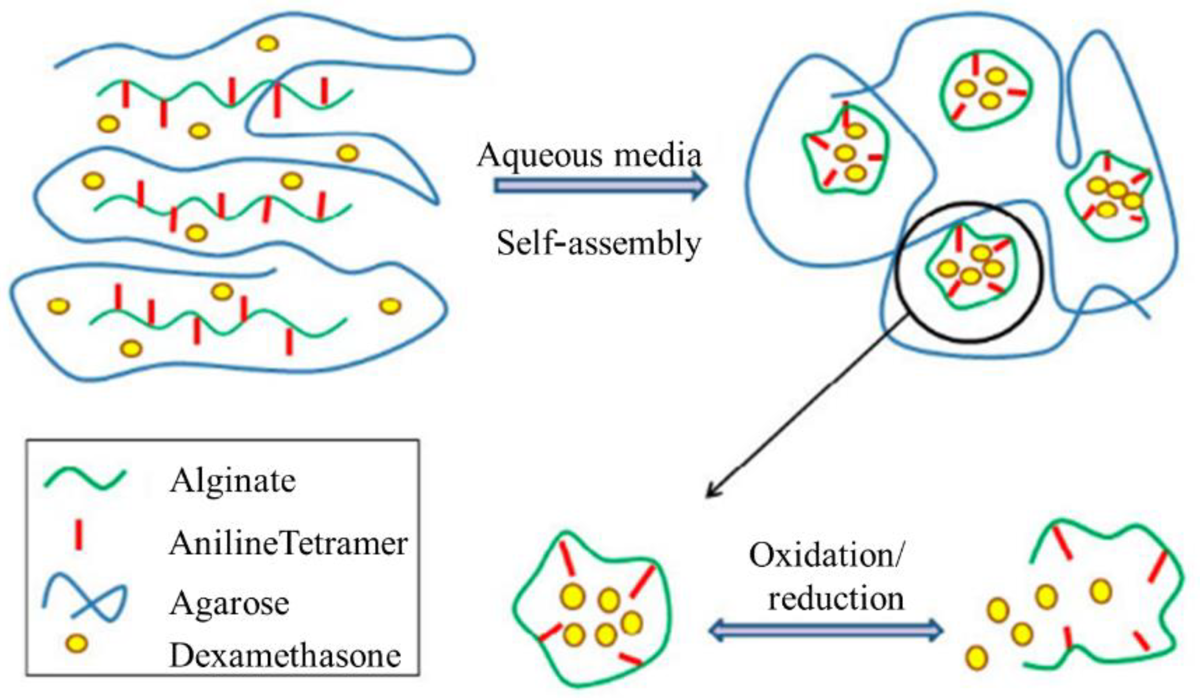
- Atoufi, Z.; Zarrintaj, P.; Motlagh, G.H.; Amiri, A.; Bagher, Z.; Kamrava, S.K. A novel bio electro active alginate-aniline tetramer/ agarose scaffold for tissue engineering: synthesis, characterization, drug release and cell culture study. J. Biomater. Sci. Polym. Ed. 2017, 28, 1617–1638. [Google Scholar] [CrossRef]
- Wu, Y.; Wang, L.; Guo, B.; Shao, Y.; Ma, P.X. Electroactive biodegradable polyurethane significantly enhanced Schwann cells myelin gene expression and neurotrophin secretion for peripheral nerve tissue engineering. Biomaterials 2016, 87, 18–31. [Google Scholar] [CrossRef]
- O’Brien, F.J. Biomaterials & scaffolds for tissue engineering. Mater. Today 2011, 14, 88–95. [Google Scholar] [CrossRef]
- Zarrintaj, P.; Moghaddam, A.S.; Manouchehri, S.; Atoufi, Z.; Amiri, A.; Amirkhani, M.A.; Nilforoushzadeh, M.A.; Saeb, M.R.; Hamblin, M.R.; Mozafari, M. Can regenerative medicine and nanotechnology combine to heal wounds? The search for the ideal wound dressing. Nanomedicine 2017, 12, 2403–2422. [Google Scholar] [CrossRef] [PubMed]
- Dong, R.; Zhao, X.; Guo, B.; Ma, P.X. Self-Healing Conductive Injectable Hydrogels with Antibacterial Activity as Cell Delivery Carrier for Cardiac Cell Therapy. ACS Appl. Mater. Interfaces 2016, 8, 17138–17150. [Google Scholar] [CrossRef] [PubMed]
- Lv, L.-P.; Zhao, Y.; Vilbrandt, N.; Gallei, M.; Vimalanandan, A.; Rohwerder, M.; Landfester, K.; Crespy, D. Redox Responsive Release of Hydrophobic Self-Healing Agents from Polyaniline Capsules. J. Am. Chem. Soc. 2013, 135, 14198–14205. [Google Scholar] [CrossRef]
- Kotwal, A. Electrical stimulation alters protein adsorption and nerve cell interactions with electrically conducting biomaterials. Biomaterials 2001, 22, 1055–1064. [Google Scholar] [CrossRef]
- Kim, H.; Jeong, S.-M.; Park, J.-W. Electrical Switching between Vesicles and Micelles via Redox-Responsive Self-Assembly of Amphiphilic Rod−Coils. J. Am. Chem. Soc. 2011, 133, 5206–5209. [Google Scholar] [CrossRef] [PubMed]
- Dong, S.; Han, L.; Cai, M.; Li, L.; Wei, Y. Synthesis of electroactive tetraaniline grafted polyethylenimine for tissue engineering. IOP Conf. Ser. Mater. Sci. Eng. 2015, 87. [Google Scholar] [CrossRef] [Green Version]
- Chang, C.-H.; Huang, T.-C.; Peng, C.-W.; Yeh, T.-C.; Lu, H.-I.; Hung, W.-I.; Weng, C.-J.; Yang, T.-I.; Yeh, J.-M. Novel anticorrosion coatings prepared from polyaniline/graphene composites. Carbon N. Y. 2012, 50, 5044–5051. [Google Scholar] [CrossRef]
- Nguyen, T.D.; Nguyen, T.A.; Pham, M.C.; Piro, B.; Normand, B.; Takenouti, H. Mechanism for protection of iron corrosion by an intrinsically electronic conducting polymer. J. Electroanal. Chem. 2004, 572, 225–234. [Google Scholar] [CrossRef]
- Mirmohseni, A.; Oladegaragoze, A. Anti-corrosive properties of polyaniline coating on iron. Synth. Met. 2000, 114, 105–108. [Google Scholar] [CrossRef]
- Sathiyanarayanan, S.; Devi, S.; Venkatachari, G. Corrosion protection of stainless steel by electropolymerised pani coating. Prog. Org. Coat. 2006, 56, 114–119. [Google Scholar] [CrossRef]
- Caldona, E.B.; de Leon, A.C.C.; Pajarito, B.B.; Advincula, R.C. Novel anti-corrosion coatings from rubber-modified polybenzoxazine-based polyaniline composites. Appl. Surf. Sci. 2017, 422, 162–171. [Google Scholar] [CrossRef]
- GUPTA, Y.; HELLGARDT, K.; WAKEMAN, R. Enhanced permeability of polyaniline based nano-membranes for gas separation. J. Memb. Sci. 2006, 282, 60–70. [Google Scholar] [CrossRef]
- Mahmoud, W.E.; Al-Ghamdi, A.A. Synthesis and properties of bismuth oxide nanoshell coated polyaniline nanoparticles for promising photovoltaic properties. Polym. Adv. Technol. 2011, 22, 877–881. [Google Scholar] [CrossRef]
- Li, Y.; Hagen, J.; Haarer, D. Novel photoelectrochromic cells containing a polyaniline layer and a dye-sensitized nanocrystalline TiO2 photovoltaic cell. Synth. Met. 1998, 94, 273–277. [Google Scholar] [CrossRef]
- Liu, B.; Huo, L.; Si, R.; Liu, J.; Zhang, J. A general method for constructing two-dimensional layered mesoporous mono-and binary-transition-metal nitride/graphene as an ultra-efficient support to enhance its catalytic activity and durability for electrocatalytic application. ACS Appl. Mater. Interfaces 2016, 8, 18770–18787. [Google Scholar] [CrossRef]
- Wang, H.; Feng, Q.; Gong, F.; Li, Y.; Zhou, G. In situ growth of oriented polyaniline nanowires array. J. Mater. Chem. A 2012. [Google Scholar] [CrossRef]
- Purves, D.; Augustine, G.J.; Fitzpatrick, D.; Katz, L.C.; Lamantia, A.S.; McNamara, J.O.; Williams, S.M. Taste perception in humans. World J. Neurosci. 2001, 7, 618. [Google Scholar]
- Scagion, V.P.; Mercante, L.A.; Sakamoto, K.Y.; Oliveira, J.E.; Fonseca, F.J.; Mattoso, L.H.; Ferreira, M.D.; Correa, D.S. An electronic tongue based on conducting electrospun nanofibers for detecting tetracycline in milk samples. RSC Adv. 2016. [Google Scholar] [CrossRef]
- Zare, E.N.; Makvandi, P.; Ashtari, B.; Rossi, F.; Motahari, A.; Perale, G. Progress in Conductive Polyaniline-Based Nanocomposites for Biomedical Applications: A Review. J. Med. Chem. 2020, 63, 1–22. [Google Scholar] [CrossRef] [PubMed]


| Mode of Electrodeposition | Difference |
|---|---|
| Galvanostatic | Deposition by applying a constant current between the counter and working electrodes |
| Potentiodynamic | Electrode potential is varied using a stable reference electrode, and the current flow is measured between the working and counter electrode |
| Potentiostatic | Deposition by applying a constant potential between working and counter electrodes |
| Sensing Materials | Preparation Method | Features | Application | References |
|---|---|---|---|---|
| Polyaniline-based pseudocapacitive glass | Facile thermal evaporation and electrodeposition methods | Excellent energy—storage and electrochromic features | Electrochromic glasses | [162,163,164,165,166,167,168,169,170,171,172,173,174] |
| Polyaniline-SO42−, BF4−, CL−, ClO4−, and p-toluene sulfonate (TsO−) | In situ electropolymerization | Easy synthesis, low price, and good conductivity features | Solar cells | [175,176,177,178,179,180,181,182,183] |
| Polyaniline-poly(styrene sulfonate) (PANI- PSS) | Chemical oxidation polymerization | An environmentally benign route for processing-controlled doping with various water-soluble polymeric or molecular dopants | Electroluminescence machines | [184,185,186,187] |
| Polyaniline (PANI)–Titanium dioxide (TiO2) ammonia gas sensors | Polymerization, spin-coating method on glass | Different structures with different morphologies, such as nanowire features | Sensors | [188,189,190,191,192,193,194,195,196,197] |
| Polyaniline, bovine viral diarrhea virus | Oxidative polymerization | Electronic and bio-molecular features | Biosensor | [198,199,200,201,202] |
| Graphene/polyaniline composites | Hydrothermal synthesis | High-capacitance electrode material feature | Supercapacitors | [78,203,204,205,206,207,208,209] |
| PANI-coated platinum (Pt) electrode | In situ polymerization | Excellent intactness and the stable nanoparticle morphology features | Neural prosthesis/biotic–abiotic interfaces | [210,211,212,213,214,215,216,217,218] |
| PU-PANI nanofibrous scaffolds | Electrospinning method | Considerable electrical conductivity, biocompatibility, and ease of synthesis | Scaffolds | [219,220,221,222,223,224,225,226,227,228,229,230] |
| Agarose/alginate-aniline tetramer | Oxidative polymerization | Possessing electroactive nature feature | Delivery systems | [231,232,233,234,235] |
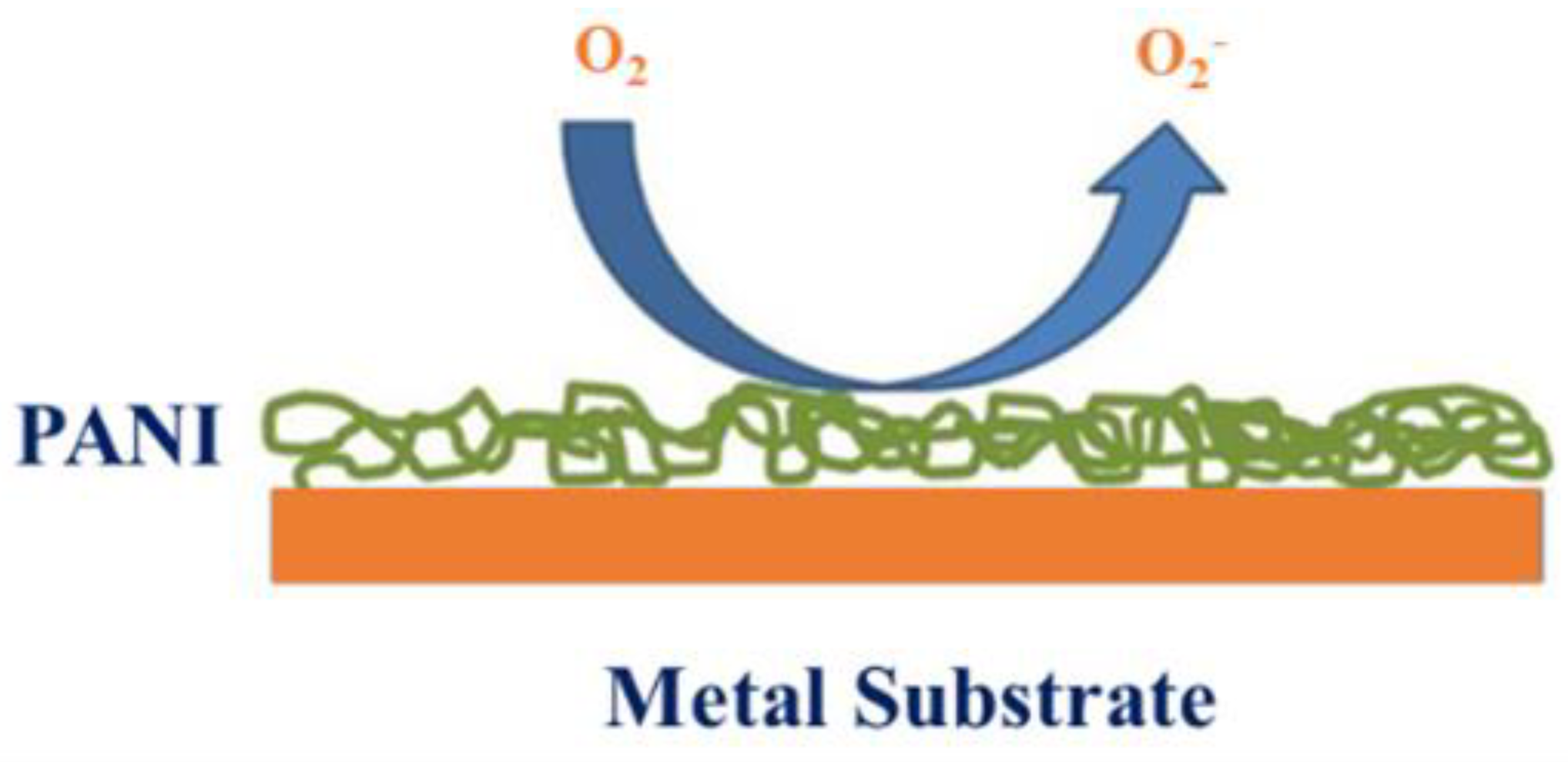
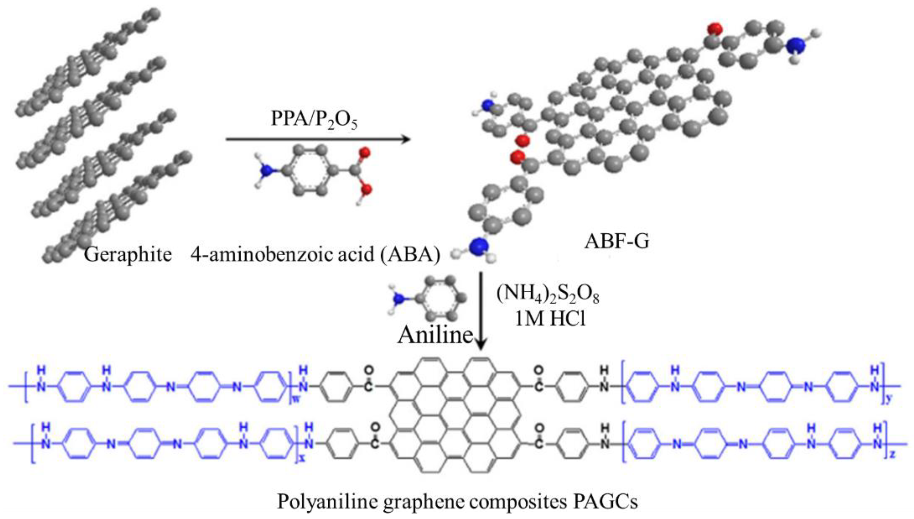
| Polyaniline/graphene composites | Chemical oxidation polymerization | Outstanding barrier features against O2 and H2O compared with neat polyaniline and polyaniline/clay composites (packs) | Anti-corrosion material applications | [236,237,238,239,240] |
| Polyaniline nano-membranes | In situ polymerization | High chemical stability feature | Gas separation membranes | [9,38,192,241] |
| Polyaniline (PANI) nanoparticles coated by nanolayer of bismuth oxide Bi2O3 | Polymerization | Possess functional groups and good structural features | Photovoltaic cells | [242,243] |
Publisher’s Note: MDPI stays neutral with regard to jurisdictional claims in published maps and institutional affiliations. |
© 2021 by the authors. Licensee MDPI, Basel, Switzerland. This article is an open access article distributed under the terms and conditions of the Creative Commons Attribution (CC BY) license (https://creativecommons.org/licenses/by/4.0/).
Share and Cite
Beygisangchin, M.; Abdul Rashid, S.; Shafie, S.; Sadrolhosseini, A.R.; Lim, H.N. Preparations, Properties, and Applications of Polyaniline and Polyaniline Thin Films—A Review. Polymers 2021, 13, 2003. https://doi.org/10.3390/polym13122003
Beygisangchin M, Abdul Rashid S, Shafie S, Sadrolhosseini AR, Lim HN. Preparations, Properties, and Applications of Polyaniline and Polyaniline Thin Films—A Review. Polymers. 2021; 13(12):2003. https://doi.org/10.3390/polym13122003
Chicago/Turabian StyleBeygisangchin, Mahnoush, Suraya Abdul Rashid, Suhaidi Shafie, Amir Reza Sadrolhosseini, and Hong Ngee Lim. 2021. "Preparations, Properties, and Applications of Polyaniline and Polyaniline Thin Films—A Review" Polymers 13, no. 12: 2003. https://doi.org/10.3390/polym13122003