1. Introduction
Thin-film/substrate systems have found increasing application in many advancing technologies, such as mechanics, civil engineering, and biotechnology [
1,
2,
3,
4]. The reliability of thin-film/substrate systems depends mainly on the interfacial adhesive strength of thin-film/substrate, which is usually from the polymeric adhesives or the generation of thin films. Therefore, the test results for adhesive strength also reflect the performance of polymeric adhesives or the effect of film generation. Usually, the determination of interfacial adhesive strength by a set of test results needs, at the same time, to know some information such as Poisson’s ratios, Young’s modulus, and residual stress of surface thin films. These information, however, are closely related to the fabrication of thin-film/substrate systems. For example, for the thin films of generation the Poisson’s ratios, Young’s modulus, and residual stress of surface thin films may have difference due to the variations in processing conditions such as temperature, humidity, or the sequence of fabrication procedures, while for the adhesive thin films, the polymeric adhesives may remain on the thin films after delamination (resulting in a change of films before adhesion and after delamination), which will make a change in Poisson’s ratios and Young’s modulus, and the conditions such as temperature and humidity may make a change in residual stress of surface thin films. So, the ideal way is that the interface and surface mechanical properties of thin-film/substrate systems should be determined by a same set of test information. This is the synchronous characterization technique so-called here. However, this technology is still in its infancy [
5].
Many test techniques have been used to the mechanical characterization of thin-film/substrate systems, but the mechanical properties of surface and interface are usually characterized separately. Conventional testing methods are mainly as follows: using approaches such as micro tensile, bending beam, ultrasonic wave, resonance frequency, indentation, X ray diffraction, optical fluorescence, Raman spectroscopy, pressure blister (or expansion), and shaft-loading blister to obtain the surface information about Poisson’s ratios, Young’s modulus and residual stress [
6,
7,
8,
9,
10,
11,
12,
13,
14,
15]; and using approaches such as vertical drawing, ultracentrifugation, supersonic vibration, transparent tape, peeling, cutting, scraping, X ray, pressure blister (or expansion), and shaft-loading blister to obtain the interface information about adhesive strength of thin-film/substrate [
16,
17,
18,
19,
20,
21,
22,
23,
24,
25]. It is obvious that the blister testing method crosses the interface and surface, and consequently it is the best one which can be used to achieve the so-called synchronous characterization technique. Taking into account that the stress concentration is very easy to occur in shaft-loading, in our previous study the pressure blister test technique was used to the interfacial mechanical properties of thin-film/substrate systems [
24]. However, our previous study [
24] failed to achieve the idea of synchronous characterization of surface and interface, while at the same time, our previous study [
5] failed to consider the residual stress in the surface thin-film of a thin-film/substrate system.
If the residual stress is present in the surface thin films, however, the analytical solution to the problem of axisymmetric deformation of a blistering thin film with initial stress will become very complicated, and consequently the concept of synchronous characterization will face some intractable technical difficulties. So, our earlier work [
5] is only applicable to the thin-film/substrate systems without residual stress. In fact, the residual stress is very easy to be present in the surface thin films due to the variations in use and processing conditions such as temperature and humidity, etc., including the case where the polymeric adhesive remains on the blistering thin films after delamination (usually the polymeric adhesive may produce contraction or expansion). So, the residual stress should be considered into the synchronous characterization technology. This is also the key issue on which this study will focus.
This paper is organized as follows: in the following section, the axisymmetric deformation problem of a blistering thin film was simplified into a circular membrane problem (a mechanical model) and the closed-form solution of the mechanical model was presented, where the residual stress in the surface thin film of thin-film/substrate systems is taken into account by regarding it as an initial stress of the circular membrane problem, and the so-called small-rotation-angle of membrane was given up. In
Section 3, the synchronous characterization of surface and interfacial mechanical properties of thin-film/substrate systems was presented, including the expressions to determine Poisson’s ratios, Young’s modulus, and residual stress of surface thin films, the elastic energy stored in the blistering film, the work done by the applied external load, the elastic strain energy stored in the enclosed compressed air, and the interfacial adhesion energy released per unit delamination area of thin-film/substrate (energy release rate). In
Section 4, some important issues were discussed, and
Section 5 contains the concluding remarks.
2. Membrane Equation and Its Closed-Form Solution
The axisymmetric deformation problem of a blistering thin film with initial stress was simplified into a mechanical model as follows: the problem of axisymmetric deformation of the peripherally fixed circular membrane with initial stress under uniformly distributed transverse loads. The problem of axisymmetric deformation of the peripherally fixed circular membrane without initial stress under uniformly distributed transverse loads was originally dealt with by Hencky, and its power series solution with the small-rotation-angle assumption of membrane was presented [
26]. This circular membrane problem is usually called well-known Hencky problem for short. A calculation error in [
26] was corrected by Chien [
27] and Alekseev [
28], respectively. This is the so-called well-known Hencky solution and it is often referred to or cited in a number of related studies [
29,
30,
31,
32,
33,
34]. Sun et al. [
35] presented the so-called extended Hencky solution, which is applicable to the membranes with or without initial stress but is still a solution under the small-rotation-angle assumption of membrane. Recently, Sun et al. [
36] resolved the well-known Hencky problem and presented a closed-form solution without the small-rotation-angle assumption of membrane but considering no initial stress in membranes. We here deal with the well-known Hencky problem once again, under the condition of giving up the small-rotation-angle assumption of membrane and taking the initial stress into account, in order to meet the requirements of the synchronous characterization. The detail derivation is as follows.
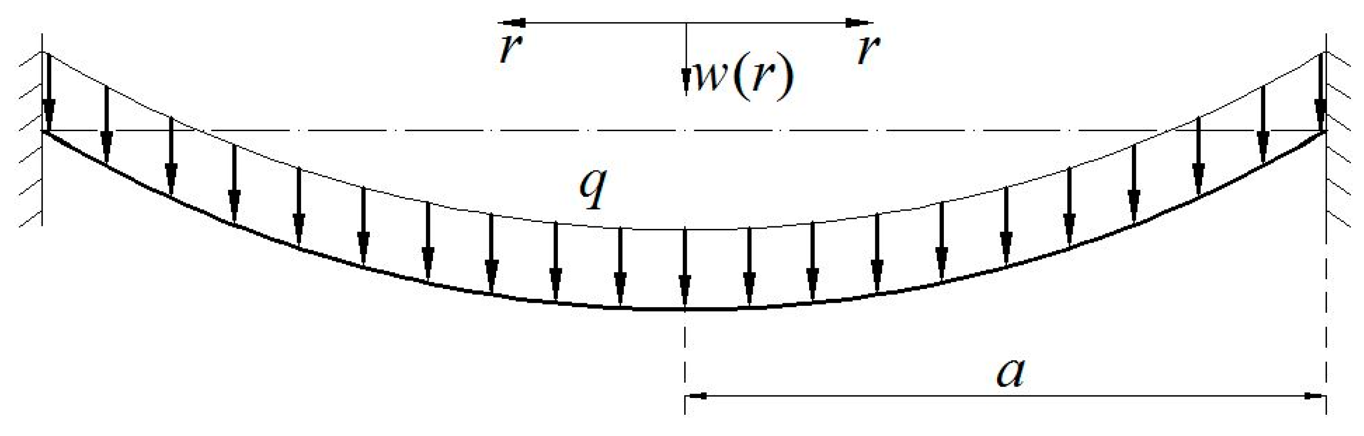
An initially flat elastic circular membrane is fixed at the perimeter of radius
after it is extended a radial plane displacement
at the radius
, and a uniformly distributed transverse loads
is applied onto the membrane surface, as shown in
Figure 1, where
is the radial coordinate and
is the transversal displacement. Suppose that the Young’s modulus of elasticity, Poisson’s ratio, radius, and thickness of the circular membrane are denoted by
,
,
and
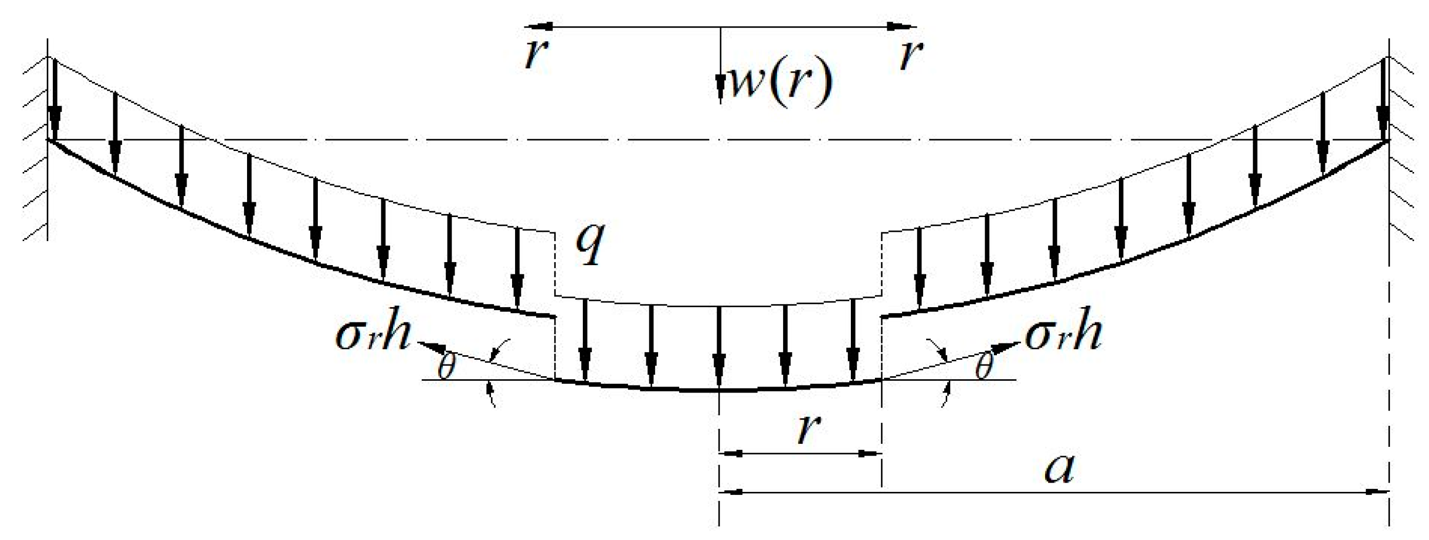
, respectively. An isolated body of radius
(
) is taken from the central portion of the circular membrane to study its static problem of equilibrium, caused by the joint action of the loads
and the membrane force
acted on the boundary, as shown just in
Figure 2, where
denotes the radial stress and
denotes the slope angle of membrane. Here, there are two vertical applied forces, the total force
(
) of the loads
and the total vertical force
produced by the membrane force
.
The out-plane equilibrium equation is
where
Substituting Equation (2) into Equation (1), one has
The radial and circumferential membrane force in the plane of the circular membrane are
and
, where
denotes the circumferential membrane stress, then the in-plane equilibrium equation can be written as
For large deflection problems of membrane, the relations of the strain and displacement are
where
,
, and
denote the radial strain, circumferential strain, and radial displacement, respectively. The relations of the stress and strain are
Substituting Equation (5a,b) into Equation (6a,b), it is found that
and
From Equations (4), (7a) and (7b), one has
Substitute the
of Equation (8) into Equation (7a), then
It is not necessary to discuss the detailed derivation from Equation (4) to Equation (9), which can be found in any general theory of plates and shells.
The boundary conditions for solving Equations (3), (4), and (9) can be determined, based on the following solution to the problem of plane stretching of the initially flat elastic circular membrane. For the case where the initially flat elastic circular membrane is extended a radial plane displacement
at
, it is obvious that
. So, from Equation (5) it is found that
Substituting Equation (10a,b) into Equation (6),
From Equations (4) and (11a,b), one has
The boundary conditions for solving Equation (12) are
So, under the conditions of Equation (13a,b), the solution of Equation (12) can be written as
Substituting Equation (14) into Equations (10a,b) and (11a,b), it is found that
Here,
denotes the so-called initial stress in the circular membrane after extending a radial plane displacement
at
(the one before applying the uniformly distributed transverse loads
, this initial stress corresponds to the residual stress in the surface thin film of a thin-film–substrate), and
denotes the initial strain. Equation (15a,b) show that, for the problem of plane stretching of circular membranes, at every point on the stretched circular membrane the radial strain
is always equal to the circumferential strain
, and also the radial stress
is always equal to the circumferential stress
. This can be used to explain the reason why the residual stress in the thin film of thin-film/substrate systems is always considered as a uniform stress [
37]. To this end, the boundary conditions, under which Equations (3), (4), and (9) can be solved, can finally be written as
The following dimensionless variables are introduced,
Transform Equations (3), (4), (8), and (9) into
and
From Equations (17) and (21), the boundary conditions Equation (16a,b) can be transformed into
Eliminating
from Equations (18) and (19), we can obtain an equation which contains only
Equation (23) can be further written as
Expanding
into the power series of the
, i.e., let
Substituting Equation (25) into Equation (24) and substituting
for
, the general solution of Equation (24) can be written as
where
is an undetermined constant, and the function
is shown in
Appendix A. Furthermore, from Equations (18) and (26), one has
Then, Equation (27) yields
where the function
is shown in
Appendix A. Further, we obtain from the integration of Equation (28)
where
is another undetermined constant, and the function
is shown in
Appendix A.
The undetermined constants
and
can be determined by using the boundary conditions as follows. From Equations (22b) and (29), one has
Substituting (26) into (21),
From Equation (31), Equation (22a) gives
Furthermore, from Equation (17a,b,c,d,e,f), Equation (32) can finally be transformed into
Hence, for the given problem where
,
,
,
,
and
are known in advance, the undetermined constant
can be determined by using Equation (33), and with the known constant
the undetermined constant
can also be determined by using Equation (30). So, all the undetermined constants can thus be determined.
Finally, from Equations (17) and (30), Equation (29) can be transformed into
The maximum deflection of the membrane should be at the central point (
), that is
Thus, the problem of axisymmetric deformation of the peripherally fixed circular membrane with initial stress under uniformly distributed transverse loads is analytically dealt with.
3. Synchronous Characterization Method of Surface and Interfacial Mechanical Properties of Thin-Film/Substrate Systems
Dannenberg [
38] first suggested using the blister test technique and subsequent investigators [
39,
40,
41,
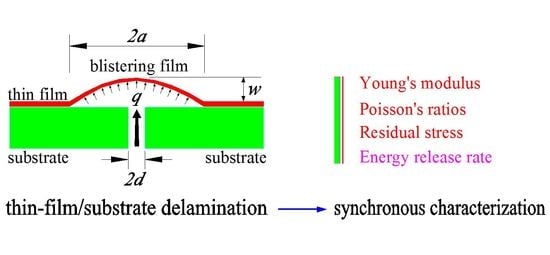
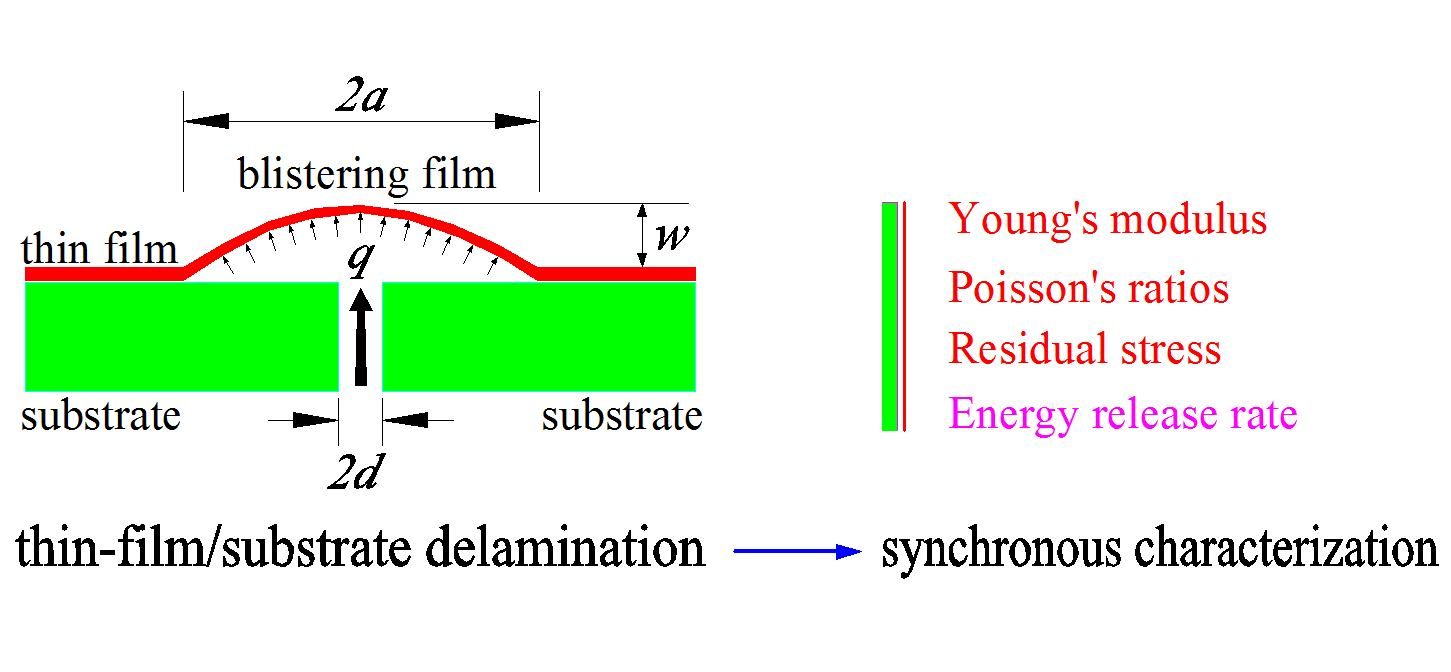
42] developed this technique into many variant forms. In all blister tests, the driving force of delamination of thin-film/substrate is applied through a hole in the substrate (which reaches the interface of thin-film/substrate by boring or chemically etching). So, the blister tests are usually classified into two major variants: (i) fluid pressure loading (corresponding to a pressure blister test, as shown in
Figure 3a), and (ii) shaft-loading (corresponding to a shaft-loaded blister test, as shown in
Figure 3b). In the pressure blister test, the overhanging thin film is pressurized progressively by either a liquid or working gas (while in the shaft-loaded blister test by a shaft), until an axisymmetric blister crack runs into the interface of film–substrate. The interfacial energy of adhesion is then determined by measuring the debonding radius
, the blister height
, and the corresponding driving force
(or
). The axisymmetric blister geometry and the small angle at the crack front are the main attractions of this technique, in comparison with peeling tests. So, we here use the pressure blister test technique.
One disadvantage of the pressure blister test is that the strain energy release rate increases with the increase of blister radius, which may give rise to uncontrolled catastrophic debonding [
43,
44]. Moreover, the pressure blister test usually requires a sophisticated experimental setup to monitor simultaneously the changes in pressure and blister dimension, which may suffer from some problems such as possible dissolved gases and the soft compliance of the gaseous medium [
42]. In order to overcome these disadvantages, in our earlier study we developed a novel loading method of pressure blister test [
24], as illustrated in
Figure 4. The two circular Plexiglas containers prepared both have a graduated scale in millimeter, and their wall thickness is about 10 mm, their height and inner radius (denoted by
,
,
,
) are 100 mm, 1500–2000 mm, 10–20 mm, and 100–400 mm (see
Figure 4). A connecting pipe of inner radius 1 mm (denoted by
) is used to connect the two Plexiglas containers. The sample of thin-film/substrate systems is prepared particularly as follows. In the substrate of the specimen, a hole of radius
(about 1 mm), drilled or chemically etched, can reach the thin-film/substrate interface. Then, the substrate of the specimen needs to be tightly adhered onto the upper side of the smaller container (see
Figure 4), so that such an adhesion can play a role in preventing air leakage. A colored liquid (the color plays only a role of eye-catching) is slowly poured into the bigger container and then flow into the smaller container via the connecting pipe. Such a pouring of colored liquid will give rise to the air enclosed in the smaller container to be compressed, resulting in a pressure loads
(compressed air) acting on the surface thin film of the sample via the hole in the substrate of the specimen. The interval time of each drop of the poured colored liquid is controlled about 1 min. The surface thin film under pressure loads
will be deformed slowly into a blister. The operation of pouring colored liquid is stopped until the blister obtained becomes measurable in size (the radius
is about 10–15 mm). The blister obtained needs some time to complete the deformation (no change in size), and then one can measure and record the radius
and height
of the unchangeable (stable) blister. After this, the colored liquid poured needs to be discharged from the bigger container via the drain hole (i.e., unloading, see
Figure 4), and the thickness
of the blistering thin film also needs to be measured and recorded.
Exactly, this static problem of equilibrium of the stable blistering film (no change in size) with initial stress (equal to the residual stress in the surface thin film of the specimen) is the large deflection problem of axisymmetrical deformation of a peripherally fixed circular membrane (radius
) with initial stress under the action of uniformly distributed transverse loads
, see
Section 2. This problem has been solved and its closed-form solution has been presented (see
Section 2). So, with the help of the closed-form solution presented in
Section 2, we can further try to develop a synchronous characterization method of surface and interfacial mechanical properties of thin-film/substrate systems with residual stress. The relevant mechanical quantities need to be synchronously characterized include Young’s modulus of elasticity
, Poisson’s ratio
, and residual stress
of surface thin films, the elastic strain energy stored in the blistering film (denoted by
), and the interfacial adhesion energy released per unit delamination area of thin-film/substrate (the energy release rate
). By studying the static problem of equilibrium of the stable blistering thin film, the surface mechanical properties
,
,
, and
can be determined, while by studying the energy problem of equilibrium of forming this stable blistering thin film, the interfacial mechanical properties
can be determined. The particular way is detailed as follows.
3.1. Determination of Poisson’s Ratios, Young’s Modulus, and Residual Stress
The uniformly distributed transverse loads
(caused by the compressed air, see
Figure 4) is applied to the surface thin film of a thin-film/substrate specimen via the hole of radius
, until it reaches
and a stable blister (no change in size) with radius
and height
is observed. The applied loads
, blister radius
, and deflections
and
are the parameters needing to be measured and recorded, where
and
denote the thin film deflection
at
and
, respectively, and the applied loads
can be determined by studying the static problem of equilibrium after the colored liquid is poured into the bigger container (the detail derivation is shown in
Section 3.2). After
, the applied loads
needs to be continued until it reaches
and another stable blister with radius
and height
is observed. The loads
, blister radius
, and deflections
and
also need to be measured and recorded. After unloading, the thickness
of the blistering thin film also needs to be measured and recorded. Suppose that the blistering thin film is kept always in elastic deformation during the loading. Then, with the measured and recorded parameters and with the help of the closed-form solution presented in
Section 2, Poisson’s ratios
, Young’s modulus
, and residual stress
are determined as follows.
When
, Equation (34) gives
and
Hence, the undetermined constant
and Young’s modulus
can be determined by using Equations (36) and (37). Then, with the known
and
, Equation (33) gives
Note that Equation (38) contains only two undetermined parameters, Poisson’s ratios
and residual stress
.
While
, Equation (34) gives
and
Hence, the undetermined constant
and Young’s modulus
can also be determined by using Equations (39) and (40). If the value of Young’s modulus
(obtained in this time) is very close to the value obtained in
, then this indicates that the blistering thin film is kept always in elastic deformation during the loading, otherwise, the test results are invalid (prepare another thin-film/substrate specimen again for test). If the results are valid (there may be some error caused usually by measurement), then, with the known
and
, Equation (33) gives
So, Poisson’s ratios
and residual stress
can thus be determined by using Equations (38) and (41).
3.2. Determination of Elastic Strain Energy Stored in Blistering Thin Films
The volume under the blistering thin film is
Studying the static problem of equilibrium of the loading system, one has
where
is the density of the liquid and
is the acceleration of gravity. Further, Equation (43) gives
Thus, the elastic strain energy stored in the blistering thin film can finally be written as
Obviously, here
should be a function of the blister radius
.
3.3. Determination of Work Caused by Liquid Potential Energy Change
It can easily be proved that the gravitational potential energy of the liquid of volume
can be expressed in
, where
is the radius of a circular container,
is the height of the liquid in the circular container. So, as shown in
Figure 4, the total change of the gravitational potential energy of the poured colored liquid in two containers, i.e., the work done by the poured colored liquid as external force to the loading system, is
Equation (46) can further be simplified into
3.4. Determination of Elastic Strain Energy Stored in Enclosed Compressed Air
The elastic strain energy
stored in the compressed air enclosed in the container of radius
can be determined via a graph of the function
or
, which can be obtained via an “assisted synchronous experiment”. The so-called “assisted synchronous experiment” is detailed as follows. Before a concrete pressure blister test, a flat steel plate is put onto the upper surface of the specimen (over the hole of radius
) to prevent the deformation of thin film during loading. Then, the colored liquid is, step by step, poured into the container of radius
, and in each step the amount of the colored liquid poured needs to keep consistent as much as possible. By studying the static problem of equilibrium in each step, one has
Hence,
where,
and
denote the liquid height in the containers of radius
and
after the operation of step
, and
denotes the pressure caused by the compressed air enclosed in the container of radius
after the operation of step
. The work done by the external force to the system, caused by the change in the amount of the colored liquid poured after the operation of step
, can be written as, from Equation (47),
According to the law of conversation of energy, the elastic strain energy stored in the compressed air enclosed in the container of radius
after the operation of step
,
, should equal to
, that is,
Step by step, and or can be recorded down, hence a graph of the function or can finally be plotted on a coordinates plane. So, in the pressure blister test that followed, using the obtained graph of the function or , the elastic strain energy stored in the compressed air enclosed in the container of radius can thus be determined, because the volume of the air enclosed originally in the container of radius in the “assisted synchronous experimentation” is equal to that in the following pressure blister test.
3.5. Determination of the Energy Release Rate
In the light of the law of conversation of energy, the work
caused by the change in the amount of the colored liquid poured minus the elastic strain energy
stored in the stable blistering film and the elastic strain energy
caused by the air compression equals exactly to the total energy released during the film–substrate delamination from the radius
to the radius
. So, for the thin films adhered uniformly to a rigid substrate, the interfacial adhesion energy released per unit delamination area of thin-film–substrate, i.e., the so-called energy release rate, can finally be written as
4. Results and Discussion
A numerical example of a circular rubber thin film with
= 20 mm,
= 1 mm,
= 7.84 MPa,
= 0.47,
= 3 MPa subjected to the uniformly distributed transverse loads
= 0.5 MPa is considered, to discuss the influence of the initial stress and small-rotation-angle assumption of membrane on the solution to circular problems. We here use four solutions to conduct the numerical calculation: the extended Hencky solution presented in [
35] (considering initial stress but obeying small-rotation-angle assumption of membrane), the solution presented in this study (considering initial stress and giving up small-rotation-angle assumption, see
Section 2), the well-known Hencky solution presented in [
30] (considering no initial stress and obeying small-rotation-angle assumption), and the solution presented in [
36] (giving up small-rotation-angle assumption but considering no initial stress).
Figure 5 shows the numerical calculation results of the variation of
with
, where the uppermost dash–dot line represents the result obtained by using the solution presented in [
35], the downward second one (the heavy solid line) by using the solution presented in this study, the downward third one (the solid line with small dots ) by the well-known Hencky solution [
30], and the down most dashed line by the solution presented in [
36]. From
Figure 5 it can be seen that, the difference between the various situations is obvious, where the difference between the uppermost line and the downward second one is caused by only the small-rotation-angle assumption of membrane, the difference between the down most line and the downward second one is caused by only the initial stress, and the difference between the downward third line and the downward second one is caused by both the initial stress and the small-rotation-angle assumption of membrane. So, in light of this, the residual stress in the surface thin film of thin-film/substrate systems (corresponding to the initial stress in circular membrane problems) have a large influence on the synchronous characterization, while at the same time, the small-rotation-angle assumption of membrane should be given up in order to improve the accuracy of theoretical solution.
Figure 6 shows the deflection differences of the circular rubber thin film with different initial stresses (
= 0, 2, 4 and 6 MPa), i.e., the effect of residual stress on the deflection of a blistering thin film.
Figure 6 indicates that the deflection will decrease along with the increase of initial stress (corresponding to the residual stress of thin-film/substrate systems). This should be easily understood, because the initial stress (or residual stress) will give rise to the increase of transverse stiffness of the membrane, resulting in the decrease of deflection of the membrane.
In our earlier study [
5], we use the shaft-loaded blister test technique for synchronous characterization, and the theoretical solution presented in [
5] is still a one with the small-rotation-angle assumption of membrane, except considering no initial stress in membranes. In fact, the shaft loading is very easily to give rise to the stress concentration, while the pressure loading can overcome the disadvantage of stress concentration. In this sense, the pressure blister test ought to be the preferred technique.
It should be pointed out that, for the thin-film/substrate systems by polymer adhesives, the polymer adhesive will adhere to the surface thin film or the substrate, after the delamination of thin-film/substrate. So, if it adheres to the surface thin film, then the determined surface mechanical properties (Poisson’s ratios and Young’s modulus of elasticity, including residual stress and elastic strain energy stored in blistering thin films) is unavoidably affected by the polymer adhesive on the surface thin film. We mean that, in this situation, the determined Poisson’s ratios and Young’s modulus of elasticity cannot be understood as the inherent properties of the thin film characterized. From
Section 3, it can be seen that, however, the determined interfacial adhesion energy released per unit delamination area of thin-film/substrate (the energy release rate) will not be affected by this situation.

 ,
, 


