Article

Microstructural Evolution and Deterioration of Shear Properties of Sn3.0Ag0.5Cu/Cu Solder Joints after Long-Term Storage at Cryogenic Temperatures

1
Chongqing CEPREI Industrial Technology Research Institute Co., Ltd., Chongqing 401332, China
2
China Electronic Product Reliability and Environmental Testing Research Institute, Guangzhou 511370, China
3
School of Mechanical Engineering, Yangzhou University, Yangzhou 225127, China
*
Authors to whom correspondence should be addressed.
These authors contributed equally to this work.
Crystals 2023, 13(4), 586; https://doi.org/10.3390/cryst13040586
Submission received: 1 February 2023 / Revised: 10 March 2023 / Accepted: 20 March 2023 / Published: 29 March 2023
(This article belongs to the Section Crystalline Metals and Alloys)

Abstract

:
In deep space exploration the exploration equipment will inevitably experience the harsh environment of cryogenic temperature. Solder joints belong to the most vulnerable parts of electronic equipment, and the harsh environment of extreme cryogenic temperature will seriously threaten the reliability of solder joints. In this paper, Sn3.0Ag0.5Cu/Cu solder joints were prepared and stored at cryogenic temperatures (−50 °C, −100 °C, and −196 °C) for up to 960 h, whilst studying the microstructural evolution and deterioration of shear properties. The results showed that the influence of cryogenic temperature on microstructure deterioration was greater than that of storage time. With the decrease of storage temperature and the extension of storage time, the Ag3Sn intermetallic compounds (IMCs) were uniformly dispersed in the β-Sn matrix; the size decreased and the number increased. After being stored at −196 °C for 960 h, some microcracks appeared at the interface of the solder joints. Meanwhile, the shear force of the solder joints was reduced by 19.02%, and the fracture mode changed from ductile fracture to ductile–brittle mixed fracture. Therefore, it is of great scientific significance to reveal the microstructural evolution and deterioration of shear properties of the solder joints under long-term storage at cryogenic temperatures.

1. Introduction

Since the 21st century, human exploration of the unknown universe has gradually shifted from Earth’s orbit to a more remote and complex deep space environment. Some countries, especially developed countries, led by the United States, Russia, the European Union, and Japan, have covered all kinds of celestial bodies in the solar system [1,2]. Additionally, China’s first Mars Exploration mission, i.e., Tianwen-1 mission, was launched in July, 2020 [3]. However, deep space exploration equipment will experience complex mechanical, thermal, and irradiation environments. Table 1 shows each celestial body’s surface temperature and rotation period [4,5]. For example, the rotation period of the Moon is 29.5 days. In each rotation cycle, the Moon’s temperature will be maintained at −180 °C for 14.7 days at night. Therefore, the detection equipment must be operated at long-term cryogenic temperatures. The cryogenic temperature is far lower than the minimum temperature of −55 °C in the military standard. This will bring potential reliability problems to the detection equipment [6,7,8]. According to statistics, more than 70% of electronic equipment failures are caused by solder joint failure on the equipment [9,10,11,12]. Therefore, it is of great scientific significance to study the rules of microstructural evolution and mechanical property deterioration of solder joints after cryogenic temperature storage.
Currently, the studies on solder joints at cryogenic temperatures mainly focus on the effect of thermal cycling on reliability [13,14,15,16]. However, there are relatively few research reports on the long-term storage reliability of solder joints under a cryogenic temperature [17,18,19]. Rahim M. et al. [20] tested the stress distribution in the chip refluxed with Sn63Pb37 solder in the range of −180 °C~150 °C. The results showed that the stress in the solder joint interconnection interface was significantly increased at the cryogenic temperature. Linda D. C. et al. [21] studied the tensile properties of Sn-Pb based solders with different Pb contents at different temperatures. The research found that the strength of Pb90Sn10 solders consistently increased as the temperature decreased, and the strength of other solders all reached a maximum near −150 °C. Significantly, the strength of Sn40Pb60 solders decreased after reaching the max, but increased after dropping to about −200 °C. Du X. et al. [22] conducted tensile tests on solder joints prepared with Sn63Pb37 and Sn3.0Ag0.5Cu (SAC305) solders at cryogenic temperatures. The results show that the tensile force of solder joints increases first and then decreases with the decrease in temperature. However, the tensile force at cryogenic temperature is still higher than at room temperature. As mentioned above, due to the variety of solder types available in the field of electronic packaging, the existing research is not systematic. Even for the same research object, the results obtained by different scholars are still controversial.
In addition, the current research on the mechanical properties of solder joints at cryogenic temperature mainly focuses on tensile behavior [23,24]. However, compared with tensile stress, shear stress has more influence on the mechanical properties of solder joints. Therefore, the shear properties of solder joints at cryogenic temperature need to be further studied to improve the database and facilitate further research. In this paper, SAC305/Cu solder joints were prepared and stored at different cryogenic temperature environments (−50 °C, −100 °C, −196 °C) for a long time (240 h, 480 h, 720 h, 960 h). The research results reveal the influence of storage temperature and time on the evolution of microstructures and the deterioration of shear properties of SAC305/Cu solder joints. The results provide a reference for further understanding the reliability of solder joints under long-term cryogenic temperature storage. This work provides relevant primary research data for the process design and application verification of spacecraft products in deep space exploration, and meets the urgent needs of space technology and industry development.

2. Materials and Methods

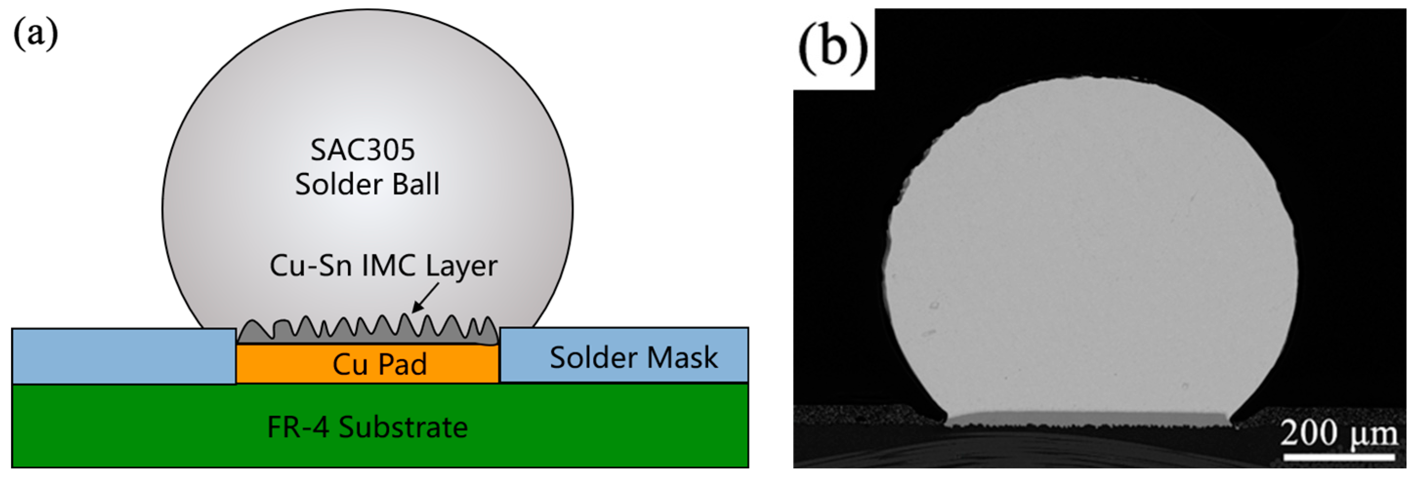
2.1. Sample Preparation

The experimental printed circuit board (PCB, made in China, manufacturer: Shenzhen Hqpcb Electronics Technology Co., Ltd., Shenzhen, China) substrate was made of glass fiber epoxy resin (FR-4), and SAC305 solder balls (made in China, manufacturer: Haipu Semiconductor (Luoyang) Co., Ltd, Luoyang, China) with a diameter of 760 μm were adopted. Cu pads with a diameter of 550 μm and a thickness of 35 μm were used as the pad materials. The pads were welded to the PCB board using surface mount technology (SMD). First, the pad surfaces were washed with anhydrous ethanol, applied with appropriate NC-559-ASM (made in American, manufacturer: Amtech Systems, Inc., Arizona, American) flux on the pad surface, and finally placed the SAC305 solder balls on the Cu pads. The reflow welding machine (model: T200N; made in Beijing, China; manufacturer: Beijing Torch SMT Incorporated Company, Beijing, China) was used to weld the SAC305 solder balls to the Cu pads. The peak reflow temperature was 245 °C and the holding time was 120 s. The schematic diagram and microstructure of the cross-section of a SAC305/Cu solder joint are shown in Figure 1. After the reflow soldering, a dark gray contrast intermetallic compound (IMC) layer was formed between the SAC305 solder ball and the Cu pad (Figure 1b).

2.2. Microstructure Characterization

The SAC305/Cu solder joints were subjected to storage experiments at cryogenic temperatures of −196 °C, −100 °C, and −50 °C, respectively. At least three samples were tested per storage experiment condition. The storage experiments at −100 °C and −50 °C were mainly carried out in an LRHS-101F-YD ultra-low temperature testing chamber (made in Shanghai, China; manufacturer: Shanghai LinPin Equipment Co., Ltd., Shanghai, China). The storage experiment at −196 °C was used to soak the samples in liquid nitrogen directly. The storage time is 240 h, 480 h, 720 h, and 960 h, respectively. After the storage experiments, microstructure analysis and shear tests of the SAC305/Cu solder joints were conducted.
The solder joint samples were ground, polished, and then etched with a chemical corrosion agent (2 vol% HCl + 3 vol% HNO3 + 95 vol% C2H5OH, made in China, manufacturer: Guangzhou Chemical Reagent Factory, Guangzhou, China) to reveal the microstructure morphologies. The internal and interface microstructures of the solder joints were observed with the Gemini SEM 300 Zeiss field-emission scanning electron microscope (FE-SEM, made in Germany, manufacturer: Carl Zeiss AG, Oberkochen, Germany). The shear test on SAC305/Cu solder joint samples was conducted using an MFM1200 push–pull tester (made in Shanghai, China; manufacturer: Shanghai TengXin Electronic Technology Co., Ltd., Shanghai, China). At least eight specimens shall be used to obtain a valuable result. The shear tests were performed according to the standard JESD22-B117, and the shear height and rate were set as 30 μm and 300 μm/s, belonging to low-speed shear. FE-SEM observed the fracture morphologies of the SAC305/Cu solder joints, and the IMC composition was analyzed using the energy dispersive spectrometer (EDS) equipped with the FE-SEM.

3. Results and Discussion

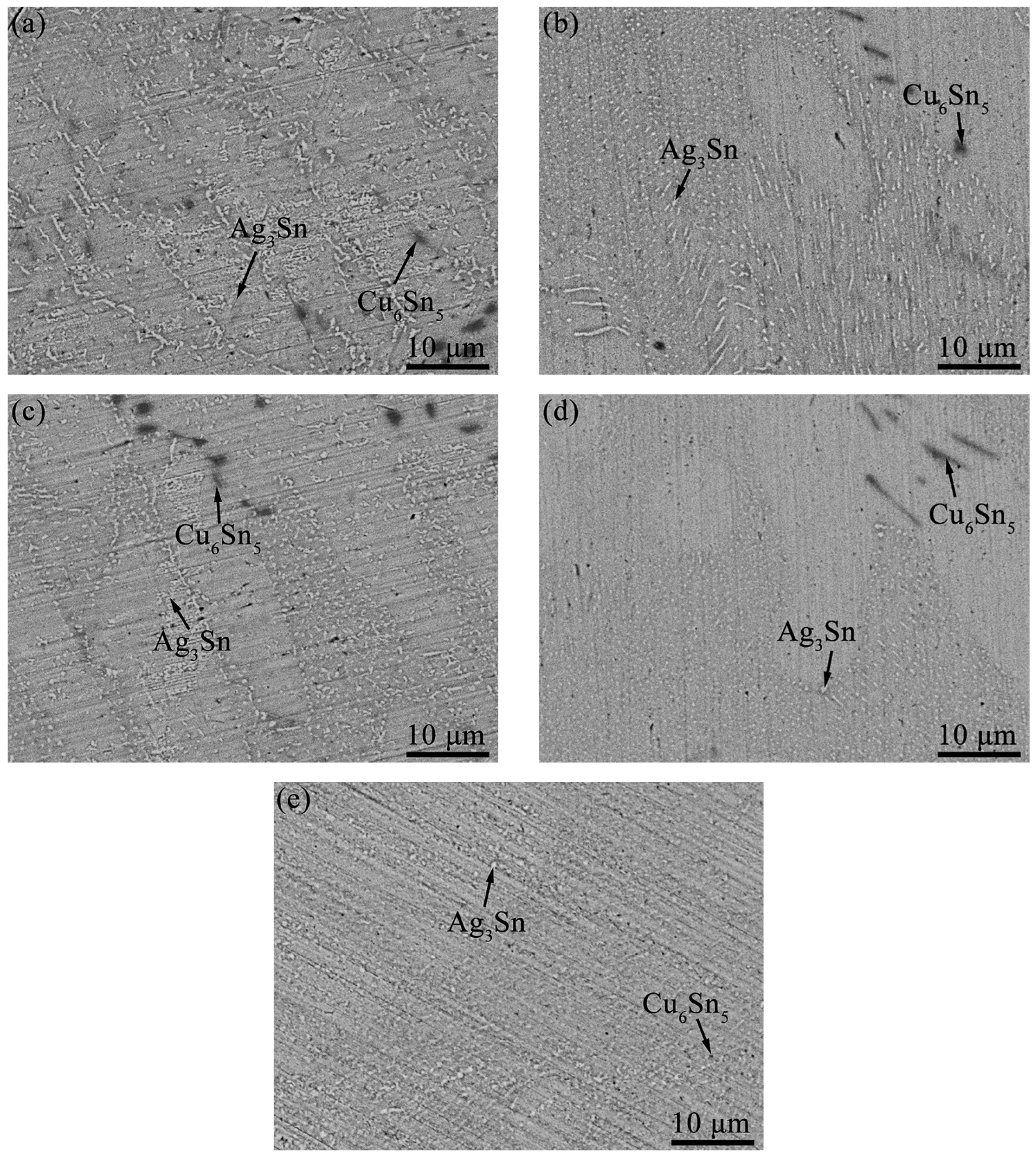
3.1. Internal Microstructural Evolution of the SAC305/Cu Solder Joints after Long-Term Storage at Cryogenic Temperatures

Figure 2 shows the internal microstructural evolution of the SAC305/Cu solder joints after long-term storage at −196 °C. The β-Sn matrix in the original internal microstructure mainly contained Ag3Sn precipitates with grey contrast and Cu6Sn5 precipitates with dark grey contrast (Figure 2a). Generally, the Ag3Sn or Cu6Sn5 precipitates mixed with the β-Sn matrix to form eutectics [25,26]. The Ag3Sn IMCs include long strip and granular forms, while Cu6Sn5 IMCs are massive. The Cu6Sn5 IMCs size is significantly larger than Ag3Sn, randomly distributed in the β-Sn matrix [27,28,29]. After storage at −196 °C for 240 h, the size of Ag3Sn becomes small and its quantity increases, which is distributed evenly and dispersedly in the β-Sn matrix. However, the size and distribution of Cu6Sn5 did not change significantly (Figure 2b).
It can be seen that the size of Ag3Sn precipitates gradually refined with the extension of storage duration, and the morphology mainly changed to small particles (Figure 2c–e). The distribution of Ag3Sn particles in the β-Sn matrix is uniform, and the fine and uniform microstructure can significantly improve the shear properties of solder joints. Under the cryogenic temperature storage state, the solid solubility of Ag atoms in the β-Sn matrix was smaller than that at room temperature. Therefore, the supersaturated Ag element migrates or precipitates from the grain to the grain boundary defects in the form of the second phase. Thus, the number of second-phase particles, Ag3Sn, increases with the storage time. At cryogenic temperature, the diffusion rate of elements becomes extremely slow, and the growth of the second phase is difficult. Therefore, Ag3Sn particles in the β-Sn matrix are evenly distributed.
Figure 3a,b are SEM images showing the internal microstructure of SAC305/Cu solder joints after storage at −100 °C at different times. Similar to the storage results at −196 °C (Figure 2), the Ag3Sn IMCs gradually refined and homogenized, and their size gradually changed into small particles with the extension of storage time at −100 °C. However, the size and distribution of Cu6Sn5 did not change significantly. After being stored for 960 h, the size of Ag3Sn particles at −100 °C was larger than that at −196 °C. This phenomenon indicated that the lower the temperature, the more significant the refining effect of low-temperature storage on IMCs. There is a valuable tool for explaining diffusion mechanisms, i.e., the equilibrium phase diagram, since it states both the nature of the phases coexisting at the interface and the driving force for the growth, either interfacial or diffusion controlled [30]. Abdulhamid et al. [31] investigated the damage mechanism of the Sn4.0Ag0.5Cu (SAC405) solder joints, and found that the Cu atom was the dominant migration element due to its faster diffusion rate than the Sn atom. Additionally, Ouyang et al. [32] subjected the thermomigration testing of SAC305 solder joints at 150 °C, and they found that the diffusion mark diffused toward the cold end. In other words, the refining of the microstructure or its evolution may occur by diffusion-controlled nucleation and growth mechanisms. Figure 3c,d are the SEM images of the internal microstructure of the SAC305/Cu solder joint after storage at −50 °C at different times. It can be seen that the morphology and size of Ag3Sn and Cu6Sn5 IMCs had not changed significantly after storage at −50 °C.

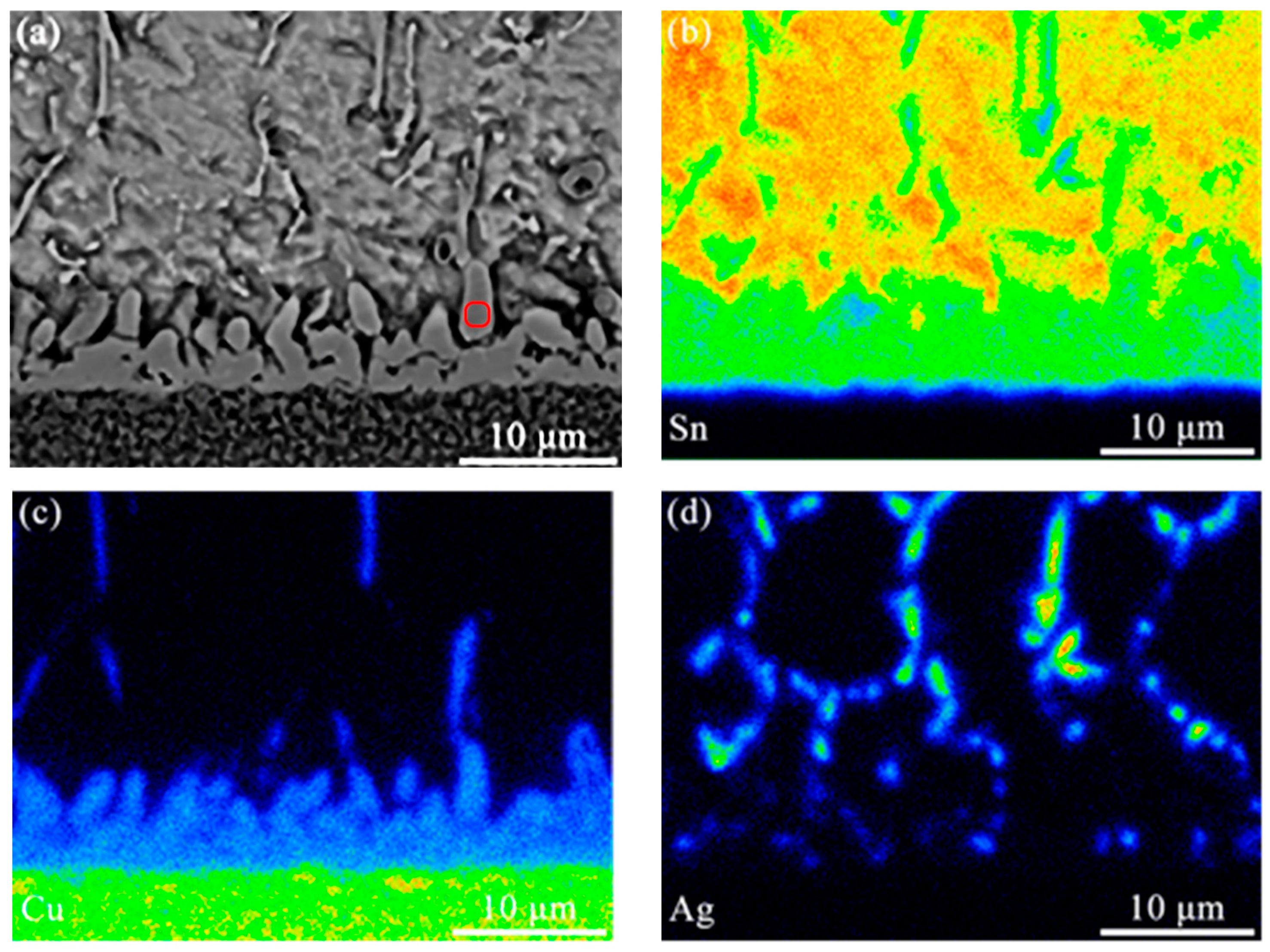
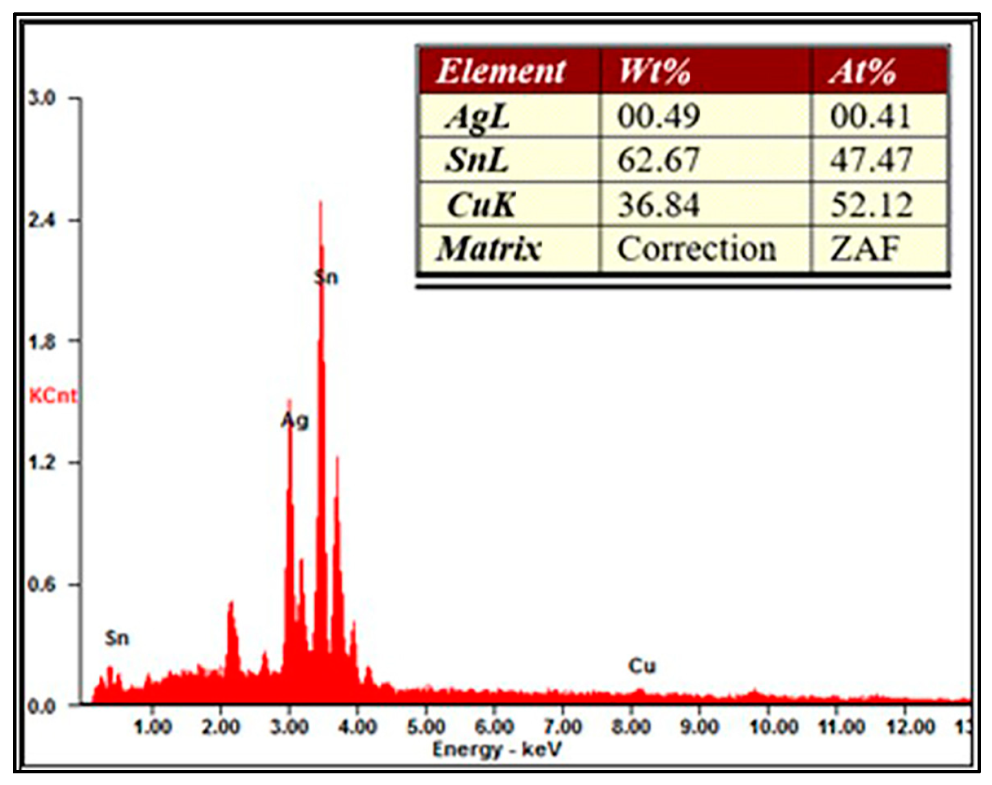
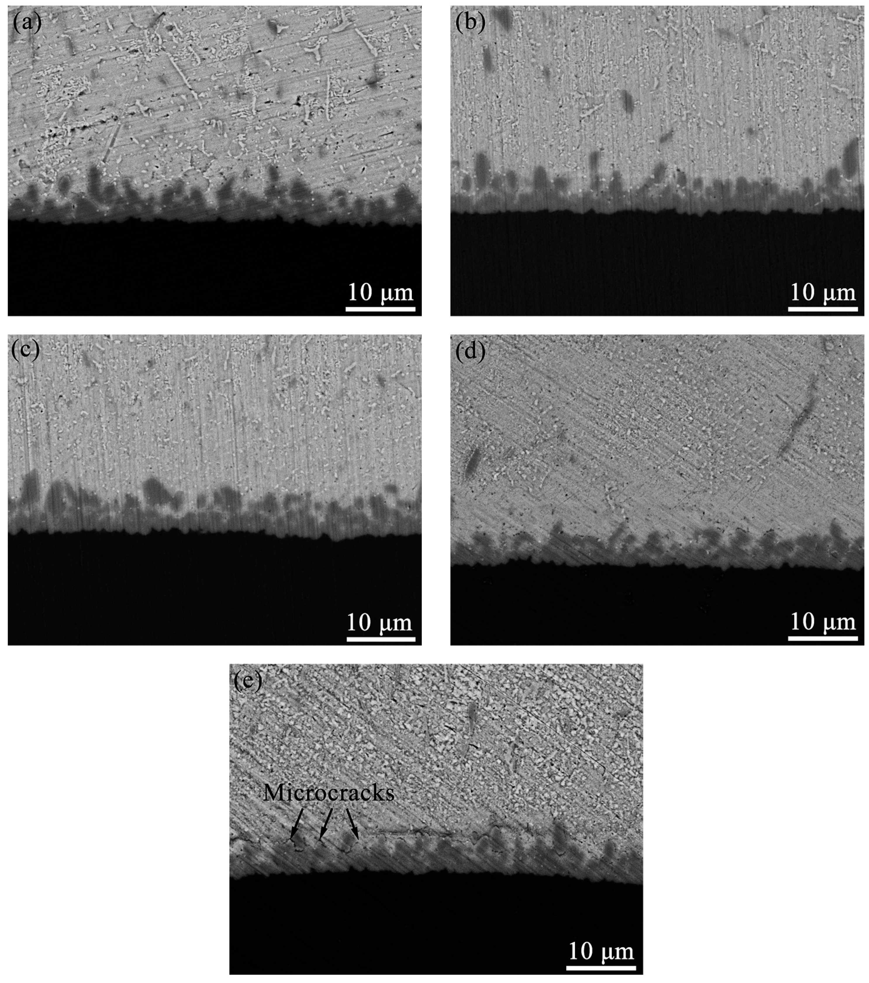
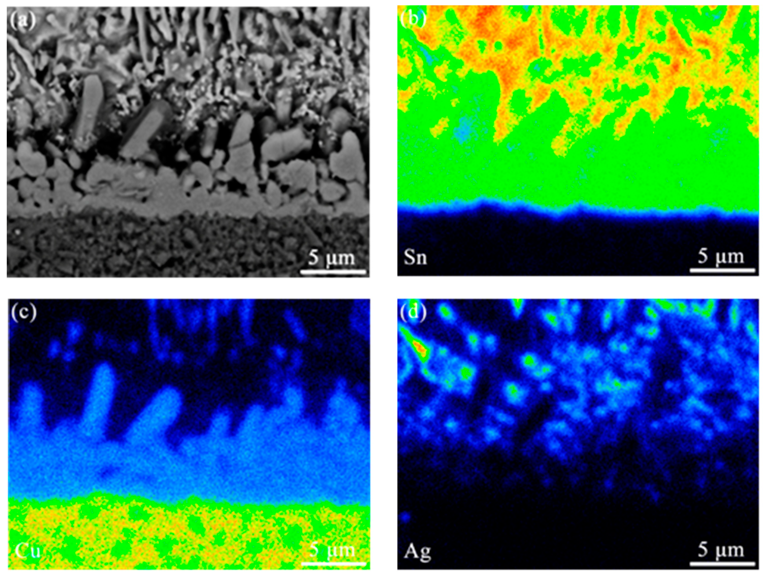
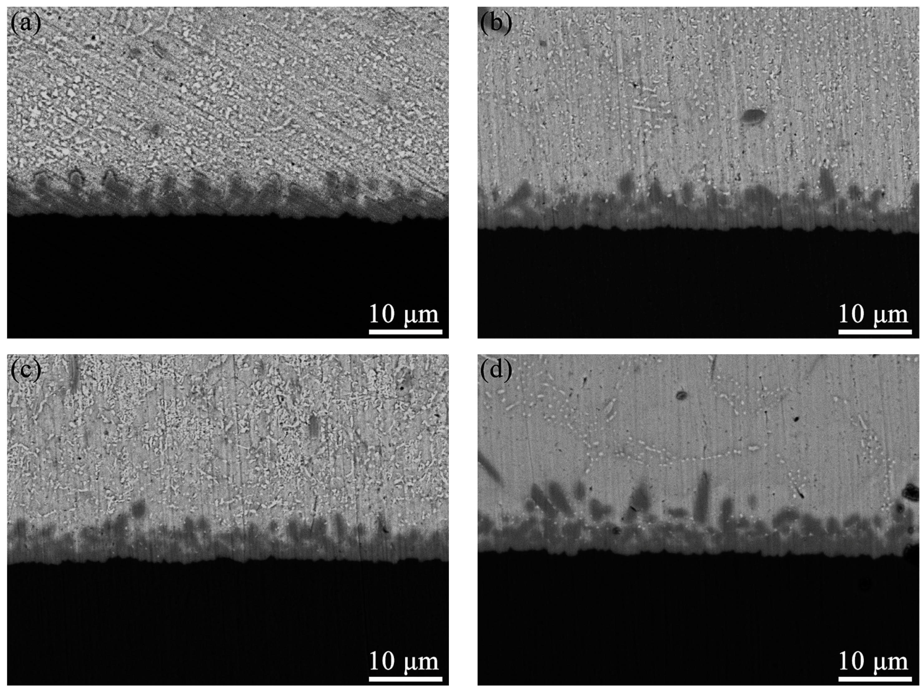
3.2. Interfacial Microstructural Evolution of the SAC305/Cu Solder Joints after Long-Term Storage at Cryogenic Temperatures

Figure 4 shows the microstructure morphology and interface element distribution of solder joints after reflow. The long-strip, granular Ag3Sn and massive Cu6Sn5 IMCs were distributed randomly and sparsely in the β-Sn matrix, as shown in Figure 4a. The IMCs at the interface of solder joints after reflow were mainly composed of short, rod-like Cu-Sn binary IMC. The mapping scanning results of EDS in Figure 4b–d revealed that the IMC was enriched in elements of Cu and Sn. Figure 5 shows the EDS analysis results of the short, rod-like compound at the solder/Cu pad interface (i.e., the red circle in the Figure 4a); the Sn and Cu are 47.47% and 52.12% (at. %), respectively. This result was consistent with the study of Hu et al. [33] and our previous studies [34,35], revealing the compound is Cu6Sn5 phase.
As shown in Figure 6, the SEM images reveal the interface microstructure of SAC305/Cu solder joints after storage at −196 °C at different times. The interface compound maintains the short rod shape, and the IMC thickness has not changed significantly with the extension of storage time (Figure 6b–d). In addition, it can be seen from Figure 6e that after being stored at −196 °C for 960 h, many microcracks appeared at the interface between the IMC and filler metal matrix. The thermal expansion coefficients of SAC305 filler metal and interface compound Cu6Sn5 are 25 × 10−6/°C and 16.3 × 10⁻⁶/°C, respectively [36], indicating that there are quite different. During storage at −196 °C, thermal expansion mismatch between materials causes thermal stress at the IMC of SAC305 filler metal/interface. Thus, the SAC305 solder is prone to creep at a higher temperature (approximate temperature > 0.3), but the approximate temperature at −196 °C is far lower than 0.3 (the melting point of SAC305 solder is 217 °C). Therefore, the solder joint cannot release the thermal mismatch stress at the interface through the creep of SAC305 solder during storage at −196 °C. Under the long-term effect of thermal stress, microcracks are formed at the SAC305 solder/interface IMC. The microstructure of shear fracture of solder joints stored at different temperatures with different storage times was analyzed, which only found cracks after long-term storage at −196 °C.
Figure 7 shows the microstructure and surface scanning analysis results of the SAC305/Cu solder joint interface after storage at −196 °C for 960 h. The interfacial IMC is still composed of Cu and Sn. EDS analysis results show that the compound is Cu6Sn5 phase. This is consistent with the results of previous researchers [33,34,35]. The storage at −196 °C has no noticeable effect on the morphology, thickness, and phase composition of the SAC305/Cu solder joint interface compound. This is because there is insufficient activation to promote the expansion reaction of materials under extremely low-temperature conditions. In this article, the results of all samples in the same group were similar, so there was no comparison between samples from the same group.
The interfacial microstructural evolution of the SAC305/Cu solder joints after long-term storage at −100 °C and −50 °C was also investigated. After storage at −100 °C and −50 °C for 240 h, the interface Cu6Sn5 IMC still maintains a short rod shape (Figure 8a,c). The morphology and thickness of the interfacial compound have not changed significantly with the extension of storage time (Figure 8b,d). This result is similar to that of cryogenic temperature storage at −196 °C. In contrast, after 960 h storage at −100 °C and −50 °C, no microcracks were found at the IMC layer/solder interface. This may be because the thermal mismatch stress generated by the solder joints at the IMC layer/solder interface under −100 °C and −50 °C storage conditions is smaller than that under −196 °C, which is not enough to cause microcracks.
As shown in Figure 8, the reduction in storage temperature or the extension of storage time had no obvious effect on the morphology, thickness, and phase composition of IMC at the interface of the solder joints. This phenomenon may be because there was not enough activation to promote the diffusion reaction of Cu atoms at cryogenic temperature, which hindered the growth of IMCs. Note that after the solder joints were stored at −196 °C for 960 h, microcracks appeared at the interface of SAC305/Cu solder joints. According to the report of Tian et al. [34], the interface stress can be expressed by Formula (1):
σ i = E i ε α i Δ T   i = 1 , 2 , 3 , 4
where  σ i  is the normal stress in each part of the solder joint structure; ε is the total strain of the solder joint structure;  E i  is the Young’s modulus in each part of the solder joint structure;  α i  is the coefficient of thermal expansion in each part of the solder joint structure; ΔT is the temperature change of solder joint structure, i.e., the difference between storage temperature and SAC305 solder solidus temperature; 1, 2, 3, and 4 represent FR4 substrate, Cu, Cu6Sn5, and SAC305, respectively.
The thermal expansion coefficients of SAC305 solder and Cu6Sn5 phase were 25 × 10−6/°C and 16.3 × 10⁻⁶/°C, respectively. In other words, the thermal expansion coefficients of SAC305 solder and the interface compound Cu6Sn5 were quite different, resulting in thermal stress at the interface of SAC305 solder. It can be seen from Formula (1) that the thermal stress at the interface will continue to increase as the temperature decreases. According to the report of Du et al. [17], when the ambient temperature is more significant than 0.3 of the solder melting point temperature, the solder can release adaptive stress at the interface through creep. However, −196 °C was far lower than the critical creep temperature of the solder joint, so the solder joint cannot release the thermal mismatch stress at the interface through the creep of SAC305 solder at −196 °C. Under the aging effect of thermal stress, microcracks are formed at the interface of the solder joints, which may lead to further failure.

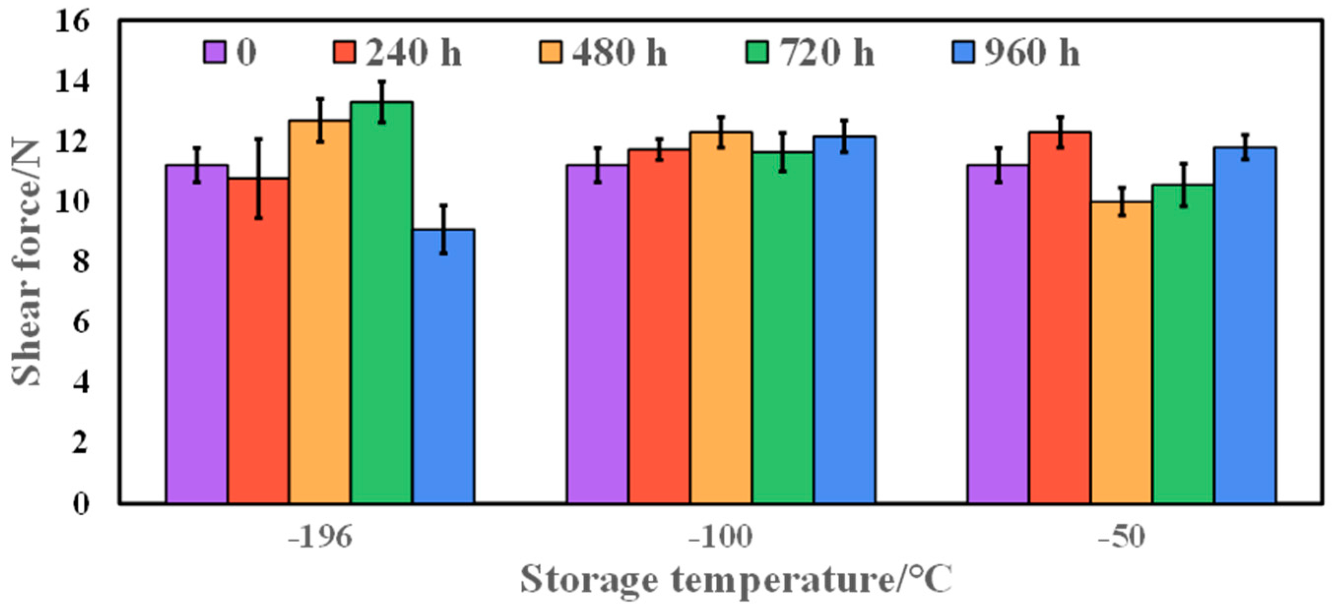
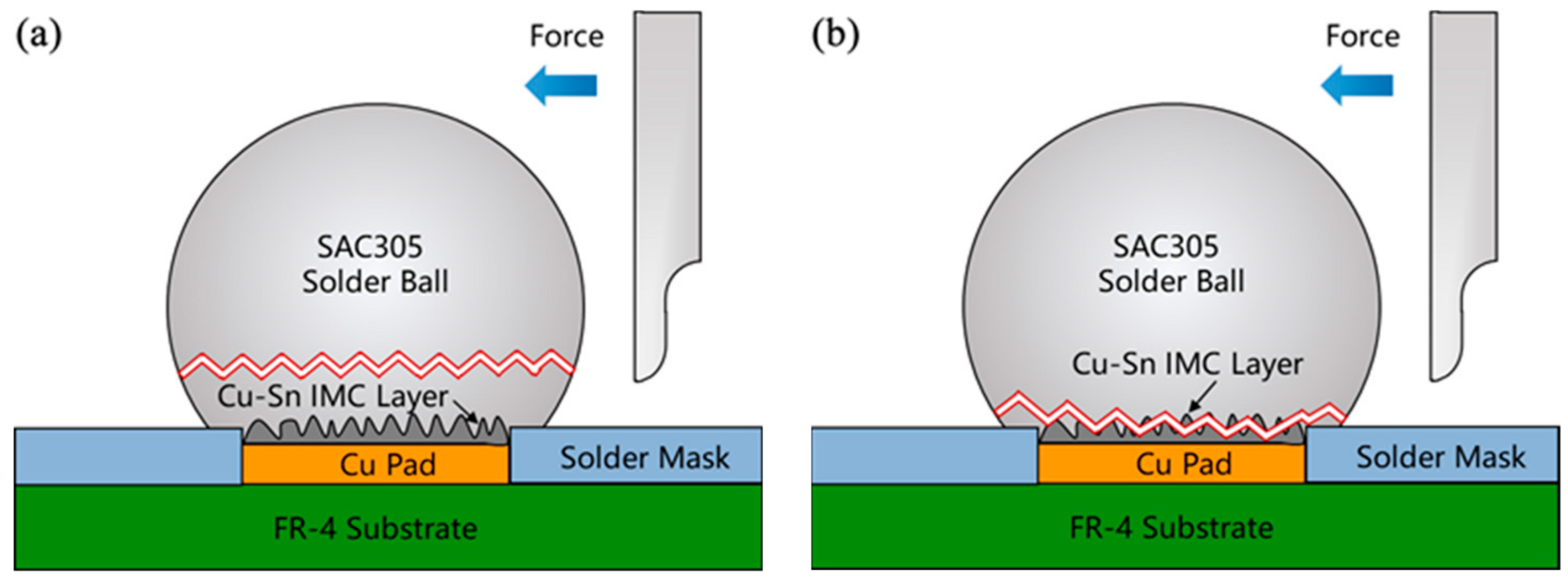
3.3. Effect of Storage Temperature and Time on Shear Properties of Solder Joints

Figure 9 shows the shear force of SAC305/Cu solder joints at different storage temperatures and times. The shear force of solder joints was 11.20 N after reflow. When the storage temperature was −50 °C, the shear force of solder joints fluctuated up and down in a particular range with the extension of storage duration. This indicates that low-temperature storage at −50 °C has no significant impact on the shear force of SAC305/Cu solder joints. When the storage temperature was −100 °C, the shear force of solder joints generally exhibited an upward trend with the extension of storage time. After storage for 960 h, the shear force of solder joints increased to 12.15 N. It should be noted that, when the storage temperature was −196 °C, the shear force of solder joints first increased and then decreased with the extension of storage time. When the storage time was extended to 720 h, the shear force of the solder joints reached the peak value (13.29 N). When the storage time was extended to 960 h, the shear force of solder joints decreased significantly, only 9.07 N (by 19.02% lower than the initial shear force). It indicates that the existence of interfacial microcracks leads to the deterioration of the shear properties of solder joints.

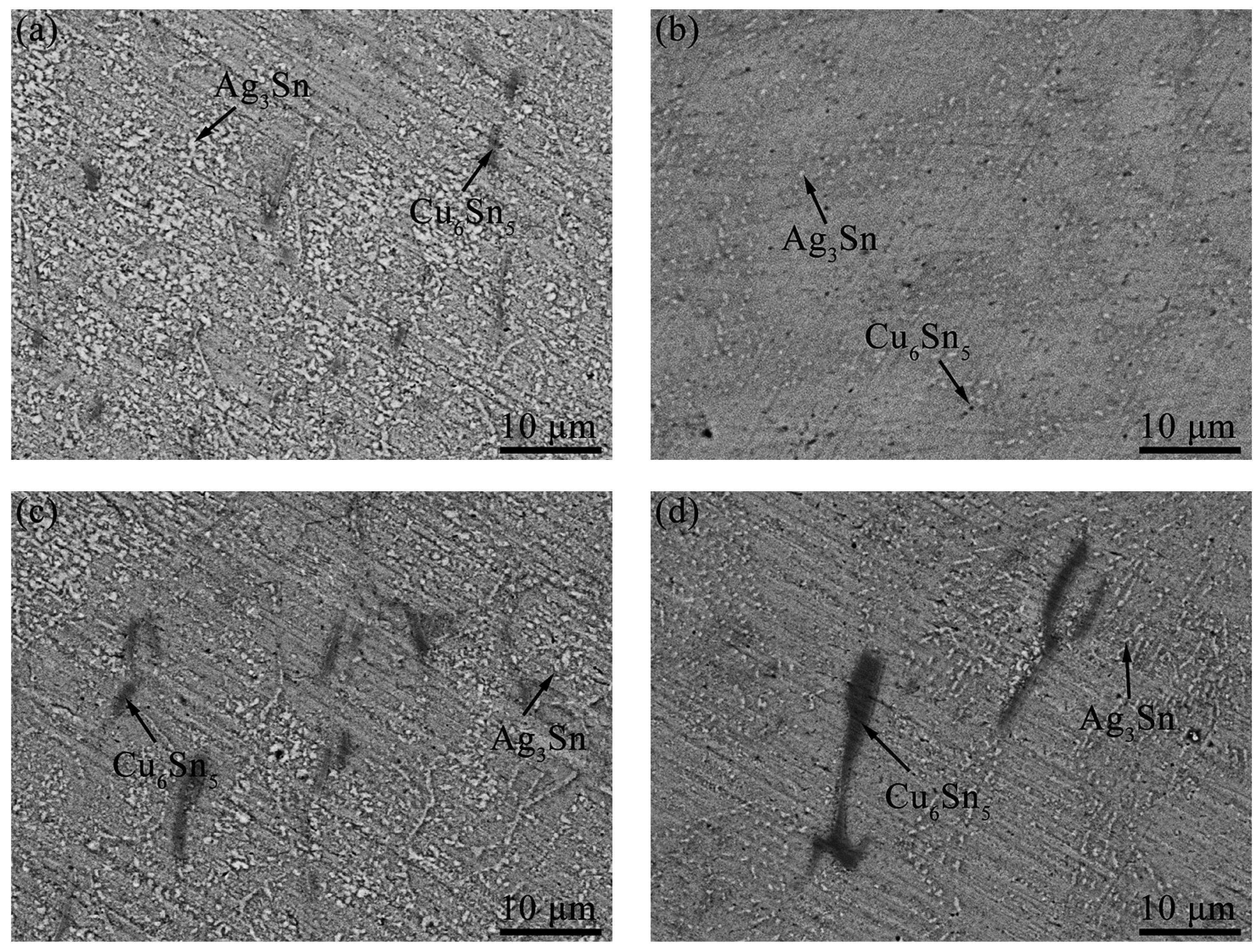
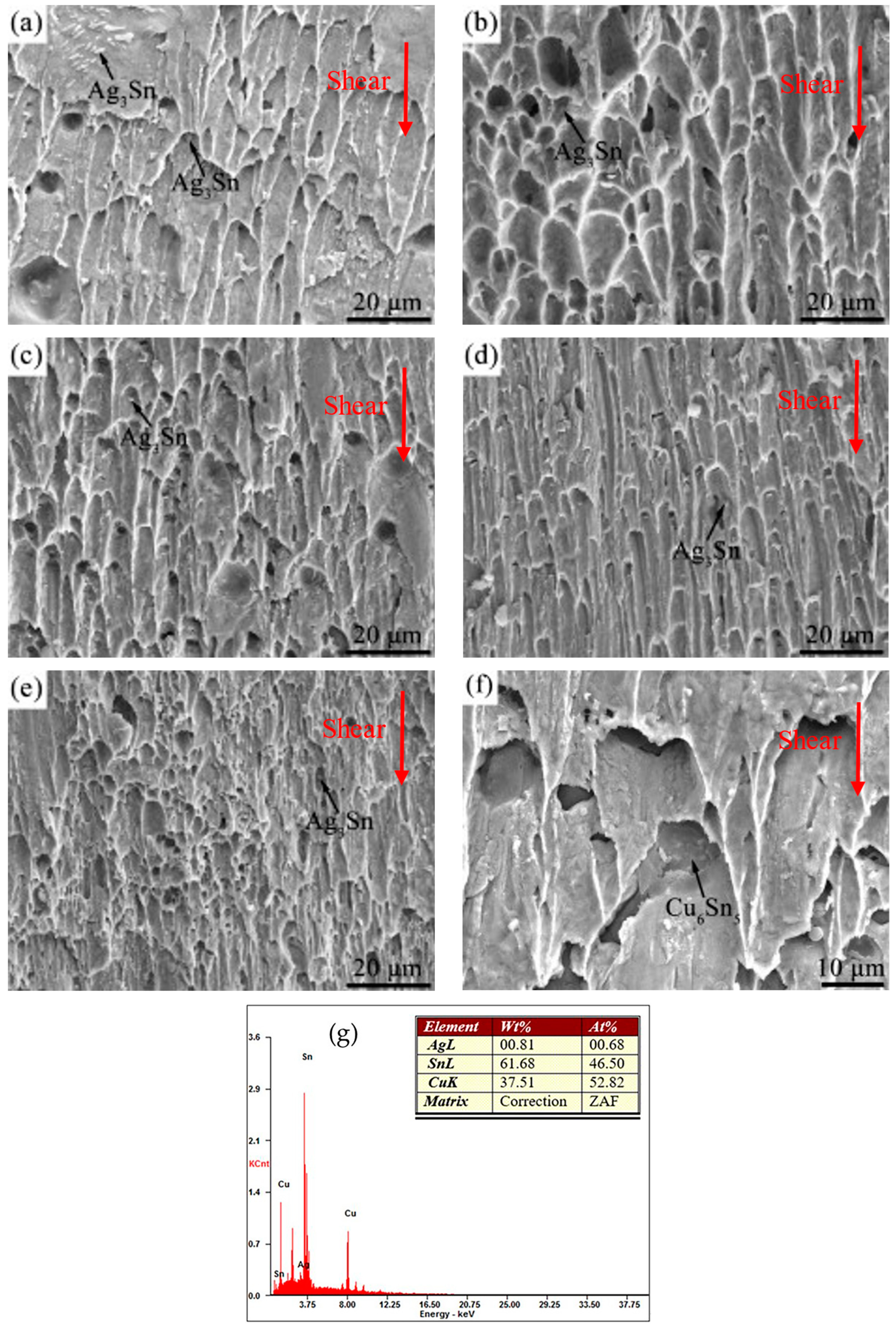
3.4. The Microstructure Characterization of Shear Fracture of Solder Joints

Figure 10 shows the microstructure of shear fracture of solder joints stored at different temperatures with different storage times. The direction of the shear force was labeled with the red arrows in Figure 10. As shown in Figure 10a, the solder joint fracture after reflow was composed of parabolic dimples. Only the Ag3Sn IMCs were observed at the bottom of the dimple, indicating that the fracture mode of the solder joints was a ductile fracture. Figure 10b shows the shear fracture morphology of SAC305/Cu solder joints stored at −50 °C for 960 h. Compared with the microstructure of the solder joint shear fracture after reflow, even if stored at −50 °C for 960 h, the dimple size and the Ag3Sn IMCs size of that did not change significantly. Combined with the research results of microstructures and shear properties of solder joints, it can be indicated that storage at −50 °C has no significant effect on the properties of SAC305/Cu solder joints. Figure 10c shows the shear fracture morphology of SAC305/Cu solder joints stored at −100 °C for 960 h, the fracture still presented a parabolic dimple shape. Its fracture mode was the ductile fracture inside the solder body. Compared with the shear fracture morphology of solder joints at −50 °C, the size of Ag3Sn at −100 °C decreases gradually and its distribution is more uniform and dispersed. The dispersed Ag3Sn particles in the solder play a role in dispersion strengthening; it is consistent with the increasing trend of the shear force of SAC305/Cu solder joints with the prolongation of storage time at −100 °C. Figure 10d shows the shear fracture morphology of SAC305/Cu solder joints stored at −196 °C for 720 h. The particle size of Ag3Sn IMCs was finer and more uniform. The fracture of the SAC305/Cu solder joint still consisted of the parabolic dimple. Figure 10e shows the shear fracture morphology of SAC305/Cu solder joints stored at −196 °C for 960 h. In addition to Ag3Sn IMCs, another type of particle was observed in the pits between the dimples. The EDS results showed that the particles were Cu6Sn5 IMCs, as shown in Figure 10g. Under the same experimental conditions, the same results were obtained for the shear fracture morphology of the samples. Therefore, the fracture morphologies of samples under the same experimental conditions are not listed here.
The fracture diagram of the SAC305/Cu solder joint of ductile fracture and ductile–brittle mixed fracture is shown in Figure 11. For the ductile fracture mode (Figure 10a–d), the crack mainly occurs in the SAC305 solder ball. Thus, the Ag3Sn IMCs inside the solder ball were observed at the bottom of the dimple (Figure 11a). For the shear fracture specimens, after 960 h storage at −196 °C, the fracture mainly occurs in the interior of the solder joint; a small part of the fracture occurs at the interface between the solder and the IMC layer. The fractured form of SAC305/Cu solder joints was a mainly ductile–brittle mixed fracture (Figure 11b). In other words, with the extension of the storage time of solder joints at −196 °C, the fracture position of SAC305/Cu solder joints transferred from the interior of the solder to the solder/IMC layer interface, which may be related to the microcracks initiated at the solder/IMC layer interface. During the shear test, the existing microcracks gradually expanded under the shear stress at the solder/IMC interface. Finally, the microcracks penetrated the solder joint, forming a ductile–brittle mixed fracture. Due to the propagation of microcracks at the interface and the change of shear fracture position of solder joints, the shear force of solder joints stored at −196 °C for 960 h would decrease significantly. It was consistent with the shear force results of SAC305 solder joints/Cu stored at −196 °C (Figure 9).

4. Conclusions

The microstructure morphology, shear properties, and shear fracture morphology of SAC305/Cu solder joints under cryogenic temperature for long-term storage were investigated, and we can draw the following conclusions:
(1) When stored at −50 °C, even if the storage time was extended to 960 h, the microstructure of SAC305/Cu solder joints was almost unchanged. When the storage temperature further decreased to −100 °C, or even below −196 °C, the internal microstructure of SAC305 solder joints revealed noteworthy aging. In other words, with the extension of storage time, the size of Ag3Sn IMCs inside the solder joint became smaller, the number increased, and they were dispersed in the solder joint.
(2) After long-term storage at −50 °C, −100 °C, and −196 °C, the phases of SAC305/Cu solder joint interface were the Cu6Sn5 IMCs, and no Cu3Sn IMCs were observed. Furthermore, the morphology and thickness of Cu6Sn5 phases almost did not change with the decreasing of temperature and the prolonging of time. It is worth noting that the microcrack appeared at the interface of SAC305/Cu solder joints after storage at −196 °C for 960 h.
(3) After the long-term storage at −50 °C, the shear force of solder joints fluctuated in a small range of around 11.2 N without apparent regularity. After long-term storage at −100 °C, the shear force of solder joints increased slightly with the extension of storage time. The peak shear force of solder joints appeared to be 12.15 N after being stored for 960 h. After long-term storage at −196 °C, the shear force of solder joints first increased and then decreased, and the peak value was 13.29 N at 720 h. Meanwhile, as the storage time was further extended to 960 h, the shear force of the solder joints decreased to 9.07 N, which was 19.02% lower than the initial shear force.
(4) There are two fracture modes for SAC305/Cu solder joints stored at low-temperature: the ductile fracture mode inside the solder joints and the ductile–brittle mixed fracture mode at the interface of the solder joints. The fracture mode of solder joints stored at −50 °C and −100 °C is not time-sensitive, and the primary fracture mode is a ductile fracture. The fracture mode of solder joints stored at −196 °C gradually changes from ductile fracture to ductile–brittle mixed fracture with prolonged storage time. The fracture position transfers from the interior of solder joints to the interface of solder joints.

Author Contributions

Investigation—X.G., X.Z. and R.T.; formal analysis—H.H. and H.X.; writing—original draft preparation, J.L. and X.G.; writing—review and editing, J.L. and Y.L. All authors have read and agreed to the published version of the manuscript.

Funding

This research is funded by the National Key R&D Program of China (Grant No. 2020YFB1710300), the National Natural Science Foundation of China (Grant No. 52105406), the Natural Science Foundation of Jiangsu Province (Grant No. BK20200940), the Science and Technology Program of Guangzhou of China (Grant No. 202201011323), and CEPREI Innovation and Development Foundation (Grant No. 22Z04 and 20Z32).

Data Availability Statement

Not applicable.

Conflicts of Interest

The authors declare that the research was conducted in the absence of any commercial or finical relationships that could be construed as a potential conflict of interest.

References

  1. Garrett, H.; Shapiro, A.; Yang, J. Interstellar Space Missions: Ultra-Reliability Requirements and Engineering Issues-Part II. In Proceedings of the 46th AIAA Aerospace Sciences Meeting and Exhibit, Reno, NV, USA, 7–10 January 2008; pp. 1–16. [Google Scholar] [CrossRef]
  2. Zhang, T.; Wang, B.; Wei, H.; Zhang, Y.; Chao, C.; Xu, K.; Ding, X.; Hou, X.; Zhao, Z. Review on planetary regolith-sampling technology. Prog. Aerosp. Sci. 2021, 127, 100760. [Google Scholar] [CrossRef]
  3. Xu, W.; Liu, X.; Yan, Z.; Li, L.; Zhang, Z.; Kuang, Y.; Jiang, H.; Yu, H.; Yang, F.; Liu, C.; et al. The MarSCoDe Instrument Suite on the Mars Rover of China’s Tianwen-1 Mission. Space Sci. Rev. 2021, 217, 64. [Google Scholar] [CrossRef]
  4. Ramesham, R. Reliability and Qualification of Hardware to Enhance The Mission Assurance of JPL/NASA Projects. In Proceedings of the 40th International Conference on Environmental Systems, American Institute of Aeronautics and Astronautics, Barcelona, Spain, 11–15 July 2010. [Google Scholar] [CrossRef] [Green Version]
  5. Blanche, J.; Strickland, M.; Knight, R.; Lall, P.; Jaeger, R.C.; Suhling, J.C.; Rahim, M.K.; Blanche, J.; Strickland, M.; Knight, R.; et al. Reliability of flip chip assemblies subjected to extreme low temperatures. In Proceedings of the Thermal and Thermomechanical Proceedings 10th Intersociety Conference on Phenomena in Electronics Systems, ITHERM 2006, San Diego, CA, USA, 30 May–2 June 2006; pp. 1379–1389. [Google Scholar]
  6. Pang, J.; Low, T.H.; Xiong, B.S.; Xu, L.; Neo, C.C. Thermal cycling aging effects on Sn–Ag–Cu solder joint microstructure, IMC and strength. Thin Solid Films 2004, 462, 370–375. [Google Scholar] [CrossRef]
  7. Chen, G.; Li, X.; Ma, J. Effect of thermal cycling on the growth of intermetallic compounds at the Sn-Zn-Bi-In-P lead-free solder/Cu interface. J. Electron. Mater. 2006, 35, 1873–1878. [Google Scholar] [CrossRef]
  8. Li, W.Y.; Zhang, X.P. Low and cryogenic temperature mechanical performance and fracture behavior of micro-scale Cu/Sn–3.0Ag–0.5Cu/Cu joints with the decreasing dimension. In Proceedings of the 2018 19th International Conference on Electronic Packaging Technology (ICEPT), Shanghai, China, 8–11 August 2018. [Google Scholar]
  9. Shen, J.; Zhao, M.; He, P.; Pu, Y. Growth behaviors of intermetallic compounds at Sn–3Ag–0.5Cu/Cu interface during isothermal and non-isothermal aging. J. Alloys Compd. 2013, 574, 451–458. [Google Scholar] [CrossRef]
  10. Jang, W.-L.; Wang, T.-S.; Lai, Y.-F.; Lin, K.-L.; Lai, Y.-S. The performance and fracture mechanism of solder joints under mechanical reliability test. Microelectron. Reliab. 2012, 52, 1428–1434. [Google Scholar] [CrossRef]
  11. Depiver, J.A.; Mallik, S.; Harmanto, D. Solder joint failures under thermo-mechanical loading conditions—A review. Adv. Mater. Process. Technol. 2020, 7, 1–26. [Google Scholar] [CrossRef]
  12. Jiang, N.; Zhang, L.; Liu, Z.-Q.; Sun, L.; Long, W.-M.; He, P.; Xiong, M.-Y.; Zhao, M. Reliability issues of lead-free solder joints in electronic devices. Sci. Technol. Adv. Mater. 2019, 20, 876–901. [Google Scholar] [CrossRef] [Green Version]
  13. Rajeshuni, R. Reliability of Sn/Pb and lead-free (SnAgCu) solders of surface mounted miniaturized passive components for extreme temperature (−185 °C to +125 °C) space missions. In Proceedings of the SPIE, San Francisco, CA, USA, 18 February 2011; p. 79280F. [Google Scholar]
  14. Rajeshuni, R. Reliability assessment of ceramic column grid array (CCGA717) interconnect packages under extreme temperatures for space applications (−185 °C to +125 °C). In Proceedings of the SPIE, San Francisco, CA, USA, 18 February 2011; p. 75920F. [Google Scholar]
  15. Rajeshuni, R. Reliability of high I/O high density CCGA interconnect electronic packages under extreme thermal environments. In Proceedings of the SPIE, San Francisco, CA, USA, 15 February 2012; p. 82500A. [Google Scholar]
  16. Ghaffarian, R. Accelerated Thermal Cycling and Failure Mechanisms for BGA and CSP Assemblies. J. Electron. Packag. 2000, 122, 335–340. [Google Scholar] [CrossRef]
  17. Lupinacci, A.; Shapiro, A.A.; Minor, A.M. A study of solder alloy ductility for cryogenic applications. In Proceedings of the IEEE International Symposium on Advanced Packaging Materials, Irvine, CA, USA, 27 February–1 March 2013; pp. 82–88. [Google Scholar]
  18. Ratchev, P.; Loccufier, T.; Vandevelde, B.; Verlinden, B.; Teliszewski, S.; Werkhoven, D.; Allaert, B. A Study of Brittle to Ductile Fracture Transition Temperatures in Bulk Pb-Free Solders. In Proceedings of the 15th European Microelectronics and Packaging Conference & Exhibition, Brugge, Belgium, 12–15 May 2005; pp. 248–252. [Google Scholar]
  19. Lambrinou, K.; Maurissen, W.; Limaye, P.; Vandevelde, B.; Verlinden, B.; De Wolf, I. A Novel Mechanism of Embrittlement Affecting the Impact Reliability of Tin-Based Lead-Free Solder Joints. J. Electron. Mater. 2009, 38, 1881–1895. [Google Scholar] [CrossRef]
  20. Kirschman, R.K.; Sokolowski, W.M.; Kolawa, E.A. Die Attachment for −120 °C to +20 °C Thermal Cycling of Microelectronics for Future Mars Rovers—An Overview1. J. Electron. Packag. 2000, 123, 105–111. [Google Scholar] [CrossRef]
  21. Del Castillo, L.; Schatzel, D.V.; Tudryn, C.; Hatake, T.; Chen, Y.; Mojarradi, M.; Kolawa, E. Extreme environment electronic packaging for Venus and Mars landed missions. In Proceedings of the 4th International Planetary Probe Workshop, Pasadena, CA, USA, 27–30 June 2006. [Google Scholar]
  22. Du, X.; Tian, Y.; Zhao, X. Mechanical properties and microstructure of Sn-based solder joints at cryogenic temperature. In Proceedings of the 2014 15th International Conference on Electronic Packaging Technology, Chengdu, China, 12–15 August 2014; pp. 888–892. [Google Scholar]
  23. Sun, Z.; Guo, X.; Zhao, Z.; Ni, Y.; He, G. Research Progress of Extreme Low Temperature Reliability of Typical Electronic Interconnection Structures. In Proceedings of the 2021 22nd International Conference on Electronic Packaging Technology (ICEPT), Xiamen, China, 14–17 September 2021; pp. 1–5. [Google Scholar]
  24. Guo, X.; Zhang, K.; Liu, J.; Li, Y.; Zuo, X.; Xiao, H.; He, G. Tensile deformation mechanism of Sn-37Pb solder alloy at cryogenic temperatures. In Proceedings of the 2021 22nd International Conference on Electronic Packaging Technology (ICEPT), Xiamen, China, 14–17 September 2021; pp. 1–4. [Google Scholar]
  25. Li, Y.; Long, W.; Hu, X.; Fu, Y. Interfacial Reaction and IMC Growth of an Ultrasonically Soldered Cu/SAC305/Cu Structure during Isothermal Aging. Materials 2018, 11, 84. [Google Scholar] [CrossRef] [PubMed] [Green Version]
  26. Maleki, M.; Cugnoni, J.; Botsis, J. Microstructure-based modeling of the ageing effect on the deformation behavior of the eutectic micro-constituent in SnAgCu lead-free solder. Acta Mater. 2013, 61, 103–114. [Google Scholar] [CrossRef]
  27. Lu, H.Y.; Balkan, H.; Ng, K.Y.S. Effect of Ag content on the microstructure development of Sn-Ag-Cu interconnects. J. Mater. Sci. Mater. Electr. 2006, 17, 171–178. [Google Scholar] [CrossRef]
  28. Han, B.; Sun, F.; Ban, G.; Liu, Y.; Liu, Y.; Li, T.; Pang, S. Effect of Cu, Ag on the microstructure and IMC evolution of Sn5Sb–CuAgNi/Cu solder joints. Mater. Res. Express 2019, 6, 086309. [Google Scholar] [CrossRef]
  29. Zhang, L.; He, C.-W.; Guo, Y.-H.; Han, J.-G.; Zhang, Y.-W.; Wang, X.-Y. Development of SnAg-based lead free solders in electronics packaging. Microelectron. Reliab. 2012, 52, 559–578. [Google Scholar] [CrossRef]
  30. Clavaguera-Mora, M.T.; Clavaguera, N.; Crespo, D.M.; Pradell, T. Crystallisation kinetics and microstructure development in metallic systems. Prog. Mater Sci. 2002, 47, 559–619. [Google Scholar] [CrossRef]
  31. Abdulhamid, M.F.; Li, S.; Basaran, C. Thermomigration in lead-free solder joints. Int. J. Mater. Struct. Integrity 2008, 2, 11–34. [Google Scholar] [CrossRef] [Green Version]
  32. Ouyang, F.-Y.; Kao, C.L. In situ observation of thermomigration of Sn atoms to the hot end of 96.5Sn-3Ag-0.5Cu flip chip solder joints. J. Appl. Phys. 2011, 110, 123525. [Google Scholar] [CrossRef]
  33. Hu, X.; Xu, H.; Chen, W.; Jiang, X. Effects of ultrasonic treatment on mechanical properties and microstructure evolution of the Cu/SAC305 solder joints. J. Manuf. Processes 2021, 64, 648–654. [Google Scholar] [CrossRef]
  34. Tian, R.; Hang, C.; Tian, Y.; Wu, B.; Liu, Y.; Zhao, J. Interfacial intermetallic compound growth in Sn-3Ag-0.5Cu/Cu solder joints induced by stress gradient at cryogenic temperatures. J. Alloys Compd. 2019, 800, 180–190. [Google Scholar] [CrossRef]
  35. Guo, X.; Xie, F.; Zuo, X.; Li, Y.; Tian, R.; Liu, J.; Wang, G. Ductile-brittle transition during tensile tests of the general solder alloys at cryogenic temperatures. In Proceedings of the 2022 23rd International Conference on Electronic Packaging Technology (ICEPT), Dalian, China, 10–13 August 2022; pp. 1–5. [Google Scholar]
  36. Li, Z.L.; Cheng, L.X.; Li, G.Y.; Huang, J.H.; Tang, Y. Effects of joint size and isothermal aging on interfacial IMC growth in Sn-3.0Ag-0.5Cu-0.1TiO2 solder joints. J. Alloys Compd. 2017, 697, 104–113. [Google Scholar] [CrossRef]
Figure 1. The schematic diagram (a) and microstructure morphology (b) of the cross-section of a SAC305/Cu solder joint.
Crystals 13 00586 g001
Figure 2. SEM-SE images of the internal microstructural evolution of the SAC305/Cu solder joints after long-term storage at −196 °C for different durations: (a) 0 h; (b) 240 h; (c) 480 h; (d) 720 h; (e) 960 h.
Crystals 13 00586 g002
Figure 3. SEM-SE images of the internal microstructural evolution of the SAC305/Cu solder joints after long-term storage at: −100 °C for 240 h (a) and 960 h (b); −50 °C for 240 h (c) and 960 h (d).
Crystals 13 00586 g003
Figure 4. Microstructure morphology and interface element distribution of solder joints after reflow: (a) Interface microstructure morphology; (b) Element mapping of Sn; (c) Element mapping of Cu; (d) Element mapping of Ag of (a).
Crystals 13 00586 g004
Figure 5. Element composition at the mark in Figure 4a.
Crystals 13 00586 g005
Figure 6. SEM-SE images of the interfacial microstructural evolution of the SAC305/Cu solder joints after long-term storage at −196 °C for different durations: (a) 0 h; (b) 240 h; (c) 480 h; (d) 720 h; (e) 960 h.
Crystals 13 00586 g006
Figure 7. Microstructure morphology and interface element distribution of solder joints after storage at −196 °C for 960 h: (a) Interface microstructure morphology; (b) Element mapping of Sn; (c) Element mapping of Cu; (d) Element mapping of Ag of (a).
Crystals 13 00586 g007
Figure 8. SEM-SE images of the interfacial microstructural evolution of the SAC305/Cu solder joints after long-term storage at: −100 °C for 240 h (a) and 960 h (b); −50 °C for 240 h (c) and 960 h (d).
Crystals 13 00586 g008
Figure 9. The shear force of SAC305/Cu solder joints after storage at different temperatures (−50 °C, −100 °C, −196 °C) with different times (240 h, 480 h, 720 h, 960 h).
Crystals 13 00586 g009
Figure 10. The microstructure of shear fracture of solder joints stored at different temperatures with different storage times: (a) reflow; (b) −50 °C for 960 h; (c) −100 °C for 960 h; (d) −196 °C for 720 h; (e,f) −196 °C for 960 h. (g) The EDS of Cu6Sn5.
Crystals 13 00586 g010
Figure 11. The fracture diagram of SAC305/Cu solder joint: (a) ductile fracture, (b) ductile–brittle mixed fracture.
Crystals 13 00586 g011
Table 1. Rotation period and surface temperature of different celestial bodies.
Celestial BodiesSurface Temperature (°C)Rotation Period (Day)
Pluto−2299.4
Moon−180~15029.5
Europa−188~−1433.6
Titan−18016
Enceladus−1964.1
Disclaimer/Publisher’s Note: The statements, opinions and data contained in all publications are solely those of the individual author(s) and contributor(s) and not of MDPI and/or the editor(s). MDPI and/or the editor(s) disclaim responsibility for any injury to people or property resulting from any ideas, methods, instructions or products referred to in the content.

