Article

The Effect of Interatomic Potentials on the Nature of Nanohole Propagation in Single-Crystal Nickel: A Molecular Dynamics Simulation Study

1
College of Materials Science and Metallurgical Engineering, Guizhou University, Guiyang 550025, China
2
School of Electronic and Information Engineering, Anshun University, Anshun 561000, China
3
Guizhou Key Laboratory for Mechanical Behavior and Microstructure of Materials, Guiyang 550025, China
4
National & Local Joint Engineering Laboratory for High-Performance Metal Structure Material and Advanced Manufacturing Technology, Guiyang 550025, China
*
Author to whom correspondence should be addressed.
Crystals 2023, 13(4), 585; https://doi.org/10.3390/cryst13040585
Submission received: 1 March 2023 / Revised: 22 March 2023 / Accepted: 22 March 2023 / Published: 29 March 2023
(This article belongs to the Special Issue Crystallization of High Performance Metallic Materials)

Abstract

:
Based on a molecular dynamics (MD) simulation, we investigated the nanohole propagation behaviors of single-crystal nickel (Ni) under different styles of Ni–Ni interatomic potentials. The results show that the MEAM (the modified embedded atom method potential) potential is best suited to describe the brittle propagation behavior of nanoholes in single-crystal Ni. The EAM/FS (embedded atom method potential developed by Finnis and Sinclair) potential, meanwhile, is effective at characterizing the plastic growth behavior of nanoholes in single-crystal Ni. Furthermore, the results show the difference between the different styles of interatomic potentials in characterizing nanohole propagation in single-crystal Ni and provide a theoretical basis for the selection of interatomic potentials in the MD simulation of Ni crystals.

1. Introduction

Fracture is a widespread and complex process of crack initiation, propagation, and coalescence, spanning a range of scales from the macroscale, mesoscale, and microscale to the atomic scale. The fracture of components is a critical issue that determines integrity and safety. At the macroscale [1,2,3,4,5,6,7,8], a variety of continuum fracture mechanics theories and empirical formulas have been established to analyze the macroscale failure behavior of materials and components. The traditional continuum fracture mechanics theory, however, is unsuitable for describing the basic physical mechanism of the failure process at the atomic scale. At the atomic scale, the essence of the fracture process of materials is the breaking of bonds that bind atoms of materials during crack initiation and propagation. Hence, atomic-scale modeling and simulations are required. The molecular dynamics (MD) simulation is a useful tool that can be used to explore the physical and mechanical properties of materials at the atomic level [9].
MD simulation is a powerful tool that can be used to study the microstructural evolution (involving dislocations, stacking faults, and twins) of plastic deformation and the fracture processes of materials [10,11,12,13]. To more systematically obtain the mechanism of deformation and fracture, crack initiation, propagation, and coalescence have been investigated based on the MD simulation. The main factors determining the crack propagation behavior are initiated crack length, crack distribution, temperature, strain rate, and the stress state of the crack tip [14,15,16,17,18,19,20].
In addition, nickel (Ni)-based single-crystal superalloys have been used in high-performance applications, such as turbine disks and blades, due to their good performance in creep resistance and fatigue resistance [21,22,23,24]. Therefore, it has been necessary to investigate the deformation, crack nucleation, and propagation mechanisms of the FCC γ phase (matrix) in the Ni-based single-crystal superalloy. Yang et al. [25] explored the effects of grain boundary structures on crack nucleation during the deformation process in a Ni-nano-laminated structure. Yao [26] studied the microstructure evolution and stress distribution of pre-crack single-crystal Ni at different temperatures. The effects of temperature, strain rate, and orientation on the crack propagation of single-crystal Ni were demonstrated by Chen [27]. Furthermore, the effects of three-dimensional defects on crack growth were investigated [28]. The crack propagation mechanisms and behaviors of crystalline Ni-based materials have been studied based on the MD simulation using different styles of interatomic potentials [29,30,31,32,33,34,35]. However, no systematic investigation has been conducted to examine the nanohole propagation behaviors and mechanisms for the different styles of Ni–Ni interatomic potentials.
In this study, we used the large-scale atomic/molecular massively parallel simulator (LAMMPS) software based on the MD simulation to investigate the nanohole propagation behaviors of single-crystal Ni at different styles of Ni–Ni interatomic potentials. We systematically compared the nanohole propagation behaviors of the three styles of Ni–Ni interatomic potentials and investigated the differences between them in characterizing the nanohole propagation of single-crystal Ni. The results offer a theoretical basis for the selection of interatomic potentials in the MD simulation of Ni crystals.

2. Simulation Conditions

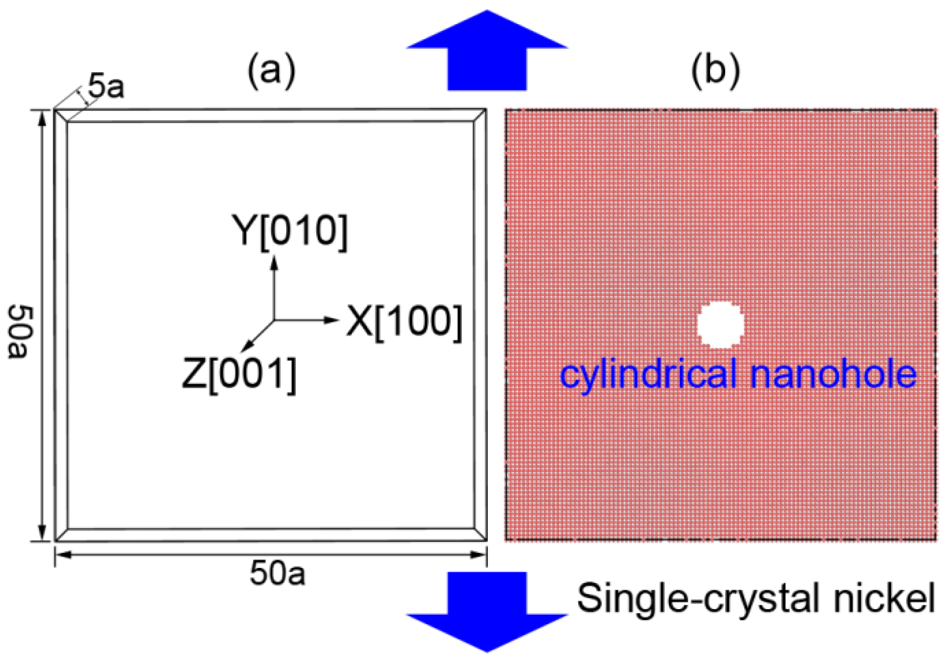
2.1. Initial Conditions

In this work, we investigated the nanohole propagation behaviors and mechanisms of single-crystal Ni according to uniaxial tensile deformation along the Y [010] direction of MD simulation models, as shown in Figure 1. The single-crystal Ni was in the cubic orientations of X—[100], Y—[010], and Z—[001]. The size of the model was 50 a × 50 a × 5 a (176 Å × 176 Å × 17.6 Å), where a = 3.52 Å is the lattice parameter of Ni crystal (Figure 1). By deleting specified Ni atoms at the central region of the deformation system, we created a model of a cylindrical nanohole with a specified size. The diameter and thickness of the nanohole were 20 Å and 17.6 Å, respectively.
We applied periodic boundary conditions in all directions. Using the conjugate gradient (CG) algorithm, we performed energy minimization by iteratively adjusting the coordinates of the Ni atoms of single-crystal Ni. Before tensile deformation, using an isothermal–isobaric ensemble (NPT) [36,37,38], we relaxed the tensile model at 20 K and 0 bar pressure for 10 ps (Tdamp = 0.01 ps and Pdamp =1 ps).Then, the tensile deformation of the system was performed at a constant temperature of 20 K, which was realized using a canonical ensemble (NVT)(Tdamp = 0.001 ps).The application of NVT ensembles means that the lateral dimensions (X and Z directions) are not allowed to relax. Uniaxial tensile deformation with a strain rate of 0.001 ps−1 was applied to the Y direction of single-crystal Ni. In the simulation, the simulation timestep was 0.001 ps. To analyze the nanohole propagation behaviors of single-crystal Ni, we visualized the atomic configurations and stress distributions of Ni atoms using the Open Visualization Tool (OVITO) [39].
To obtain the nanohole propagation behaviors, we calculated the atomic stress definitions of the front of the nanohole during tensile deformation and the average atomic stress σ α β i [40,41,42] as follows:
σ α β i = 1 2 Ω i j i N f α i , j r β i , j
where α and β represent x, y, or z; N is the number of the atoms in a region around i within a potential cutoff distance; f α i , j is the vector component form of the interaction force exerted by atom j on atom i; r β i , j is the vector component form of the relative position form of atom j on atom i; and Ω i is the volume of atom i given by the calculation of the Voronoi tessellation of the atom i in the simulation box.
In addition, the microstructure evolution of the tensile system was analyzed using common neighbor analysis (CNA) [43,44] and the dislocation extraction algorithm (DXA) of the model.

2.2. Potential between Atoms

We applied the three styles of potentials in our MD simulation—namely, the modified embedded atom method potential (hereinafter referred to as the MEAM potential) [45], the embedded atom method potential developed by Finnis and Sinclair (hereinafter referred to as the EAM/FS potential) [46], and the embedded atom method potential developed by Foiles and Baskes (hereinafter referred to as the EAM potential) [47]. Furthermore, the relevant parameters of the MEAM, EAM/FS, and EAM potentials are included in Supplementary Materials.

3. Simulation Results and Discussion

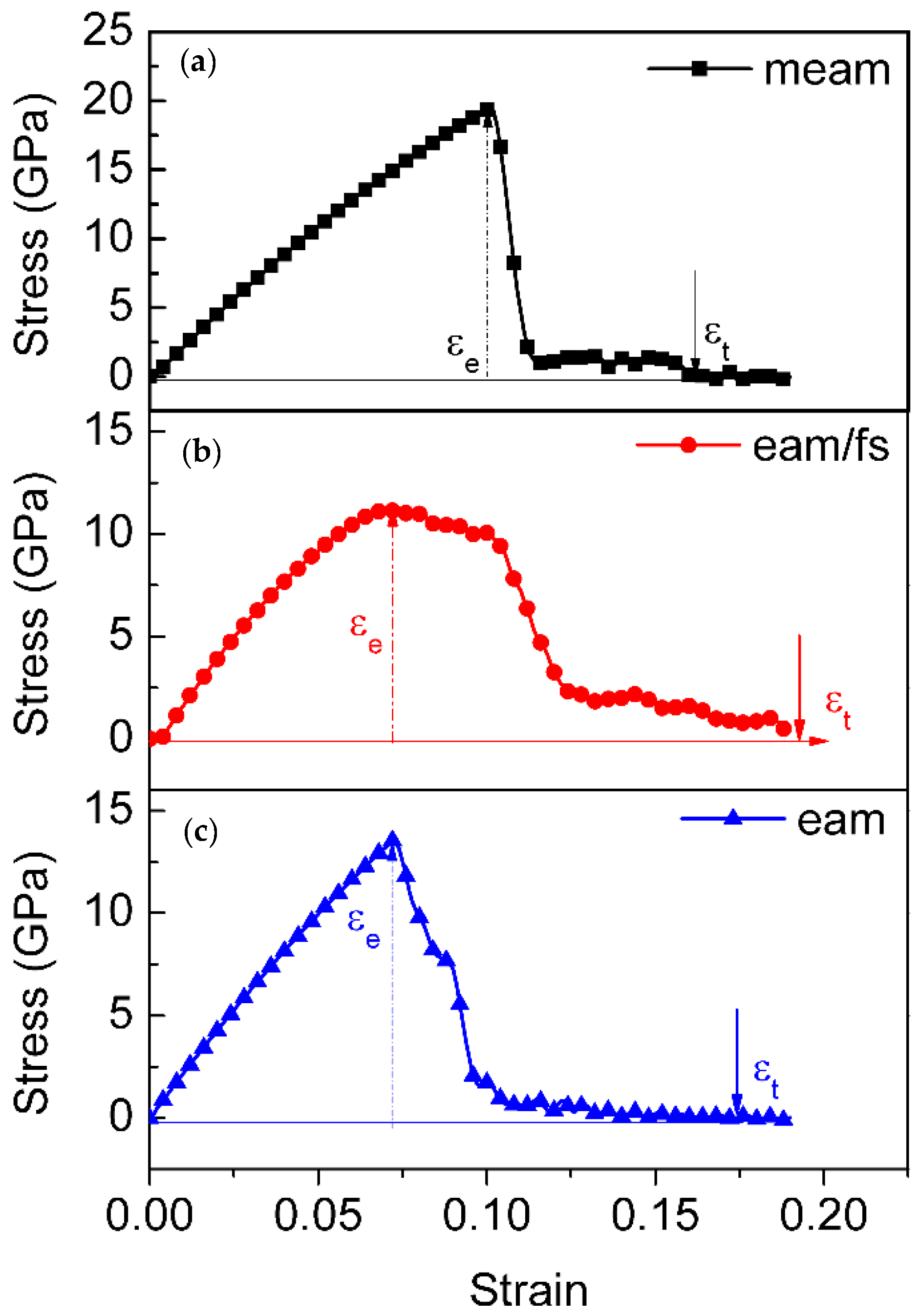
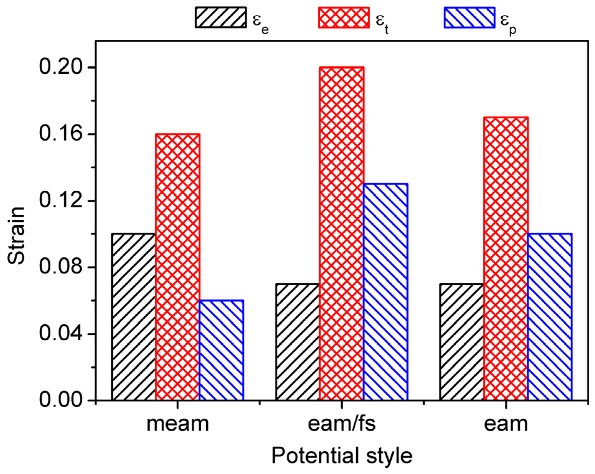
3.1. Stress–Strain Behavior

Figure 2 shows the stress–strain behavior of single-crystal Ni at various interatomic potentials, comprising the (a) MEAM potential, (b) EAM/FS potential, and (c) EAM potential. For the different styles of Ni–Ni interatomic potentials, during the initial stage of tensile deformation, the single-crystal Ni exhibited different stress–strain behaviors. ε denotes the tensile strain, and ε e , ε p , and ε t denote the elastic, plastic, and total strain, respectively. When ε < ε e , the tensile process was in the elastic deformation stage. It was when the tensile stress of these models reached the peak stress that the tensile process began to enter the plastic deformation stage (the peak stress denoted the yield stress). For the MEAM potential, after the tensile stress reached its peak, it decreased quickly to zero with an increase in strain (Figure 2a). The accumulated plastic strain, which was defined as the total strain ( ε t ) at the fracture minus the elastic strain ( ε e ) [48,49], was only 6% (as shown in Figure 3). Conversely, in the process of the plastic deformation of single-crystal Ni at the EAM/FS potential, the flow stress dropped slowly to non-zero followed by a jerky flow and gradual decrease. This feature indicated the representative ductile nature of single-crystal Ni (Figure 2b), and this ductile nature was further demonstrated by the accumulated plastic strain of 13% (Figure 3). As shown in Figure 2 and Figure 3, the stress– strain behavior of single-crystal Ni at the EAM potential also had the stress–strain characteristics of single-crystal Ni at the MEAM potential and EAM/FS potential. The accumulated plastic strain was 10% (between 6% of the MEAM potential and 13% of the EAM/FS potential).

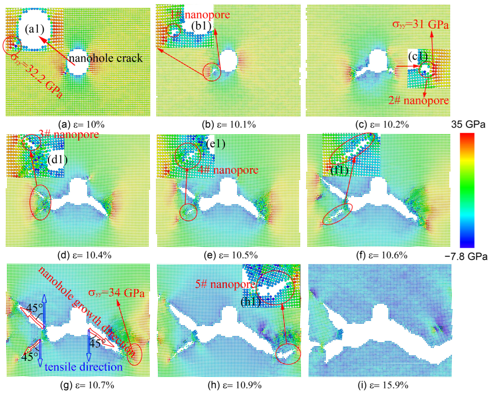
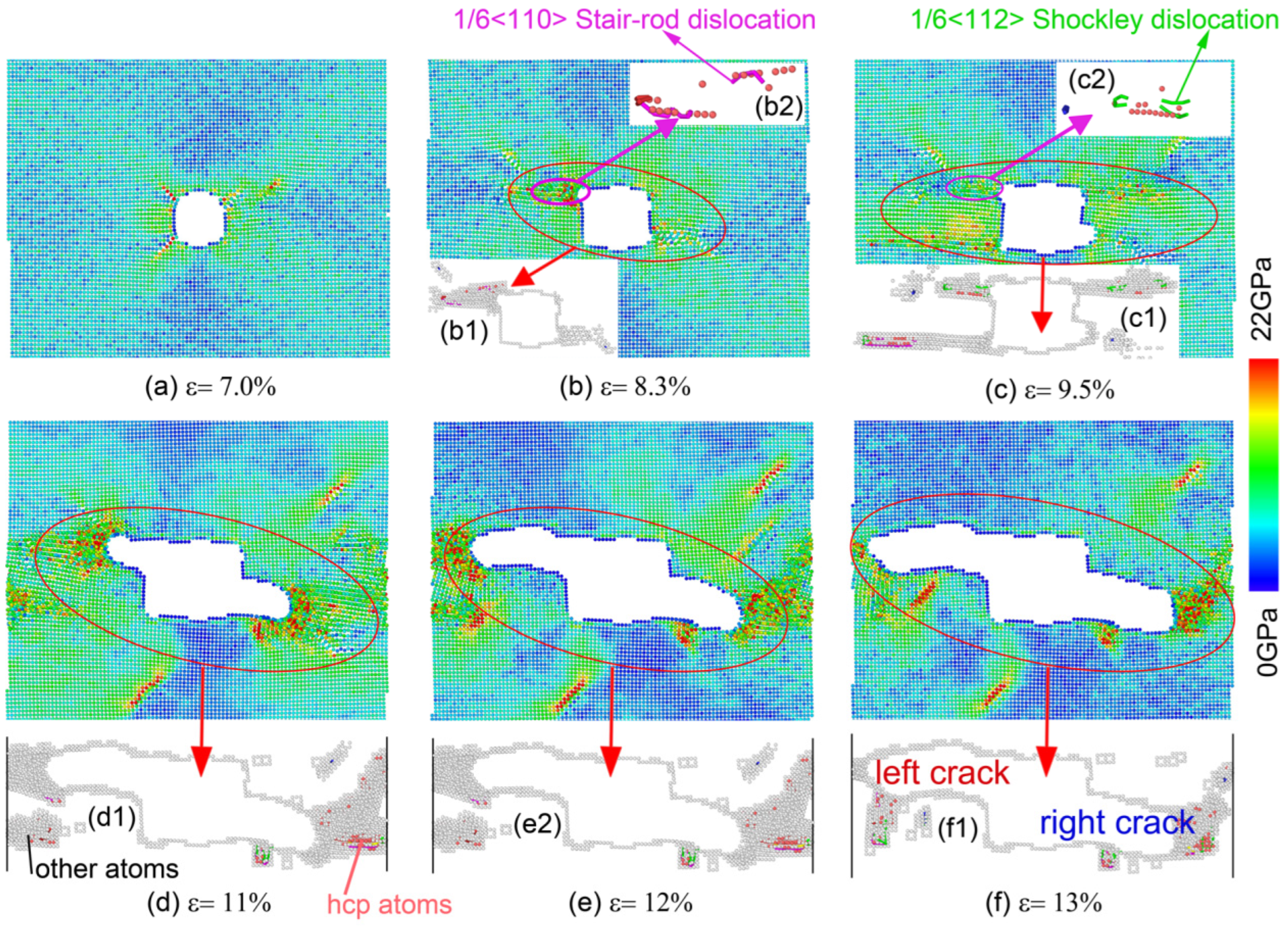
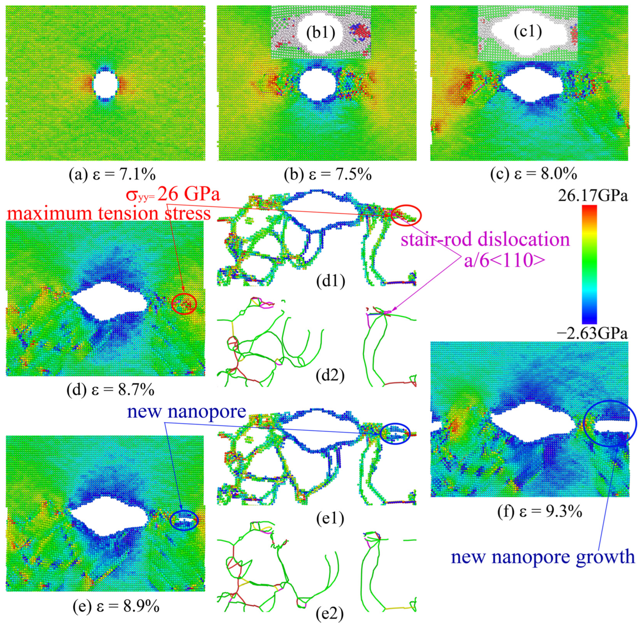
3.2. Nanohole Propagation Behavior

As the MEAM potential was used to study the nanohole propagation process, we found that the central nanohole propagated first using a fast brittle propagation model that included the process of formation and coalescence of nanopores at the front of the nanohole, as shown in Figure 4. In the process of uniaxial tensile along the y direction, the stress concentration was present at the left and right sides of the region of the central nanohole (see (a1) inset in Figure 4). When ε increased from 0% to 10.1%, the no. 1 nanopore formed at the left-bottom corner of the central nanohole because the relevant atoms of this region had a maximum tensile stress (about σyy = 32.2 GPa). As the ε value increased, the no. 1 nanohole gradually grew and coalesced with the main nanohole. At the same time, the no. 2 nanopore formed at the right-bottom corner of the main nanohole due to the stress concentration (ε = 10.2%, σyy = 31 GPa; see Figure 4(c1)). Then, the no. 2 nanopore gradually grew and coalesced with the main nanohole, and the left region of the main nanohole also produced two nanopores (no. 3 and no. 4 nanopores). As shown in Figure 4d, the plastic deformation occurred in the upper local area of the right nanopore. When ε = 10.7%, the new no. 3 and no. 4nanopores continued to grow, and the misorientation between the tensile direction and the nanohole growth direction was 45°, indicating that the crack mainly propagated along the (110) plane of single-crystal Ni (see Figure 4g). Meanwhile, the stress concentration was present in the region of the front of the right-bottom corner of the propagated nanohole (Figure 4g; σyy = 34 GPa), which gave rise to the new no. 5 nanopore initiation (Figure 4h). As ε = 15.9%, the nanohole propagated across the whole single-crystal Ni (Figure 4i). When the ε value was below 10.4%, the nanohole was propagated using a fast brittle propagation model that included the process of formation and the coalescence of nanopores at the front of the nanohole with almost no emission of dislocations from the nanohole. With the strain increasing from 10.4% to 10.9%,however, the process of nanohole propagation was accompanied by the emission and slip of dislocations.
Figure 5 shows the process of the uniaxial tensile of single-crystal Ni with the EAM/FS potential. To conveniently analyze the structural change in the nanohole local region during the nanohole propagation process, we performed a CNA and deleted the perfect atoms of the FCC structure, as shown in Figure 5(b1–f1), in which the gray and red atoms denote the amorphous atoms and the HCP structure atoms, respectively. The insets of Figure 5(b2,c2) show the change in dislocation type of different tensile strains. From Figure 5, we found that the front of the nanohole first presented stress concentration, and then the stress concentration level increased with the tensile strain. To decrease the stress concentration of the local region of the front of the nanohole, the nanohole propagation was carried out by changing the shape from a cylindrical nanohole to a rectangular nanohole (Figure 5a,b). When ε = 8.3%, the stress concentration of the nanohole resulted in the lattice structure transformation of the local region of the front of the nanohole (from a perfect FCC structure to amorphous atoms (gray atoms) and an HCP structure (red atoms); Figure 5b1). We also found that the stair-rod dislocations with a Burgess vector of a 6 1 01 appeared at the boundary between the region of amorphous atoms and the perfect FCC structure (see Figure 5(b2), the magenta dislocation line). The stair-rod dislocation with a Burgess vector of a 6 1 01 was formed through the dislocation reaction of a 6 112 + a 6 2 1 1 a 6 1 01 . The dislocations of b = a 6 112 and b = a 6 2 1 1 were Shockley partial dislocations. The stair-rod dislocation (also called the Lomer–Cottrell lock) further impeded the advance of the slip and resulted in a pile-up of the dislocation. Consequently, as the strain increased, the nanohole growth of the left-upper corner was hindered by the Lomer–Cottrell lock (as shown in Figure 6; see the red platform of the left nanohole length–strain curve). For the right-bottom corner of the nanohole, the nanohole was blunted throughout the local region atom’s amorphization to release a stress concentration, and a Lomer–Cottrell lock did not form. Therefore, the nanohole growth of the right-bottom corner was not hindered. When ε = 9.5%, the Lomer–Cottrell lock of b = a 6 1 01 disappeared from the left-upper corner of the nanohole via the relative motion of atoms in the local region. Therefore, the effect of the pile-up of the dislocation of the Lomer–Cottrell lock was removed. Two Shockley partial dislocations of b = a 6 1 21 and b = a 6 1 2 1 also formed (see the green line in Figure 5c2). Then, the nanohole propagated in the way of the local region crystal structure transformation and the dislocations slip (Figure 5d–f and Figure 6).
Figure 7 shows the process of the uniaxial tensile test of single-crystal Ni for the use of EAM potential. When ε = 7.1%, the stress concentration was present at the left and right regions of the nanohole (Figure 7a). Then, with an increase in tensile strain, the stress concentration level of the nanohole local region increased gradually, resulting in the formation of an amorphous structure in this region (Figure 7(b1,c1)), and the dislocations started to nucleate at the boundary between the region of the amorphous structure and the perfect FCC structure. The dislocation slips of the front of the nanohole resulted in nanohole propagation (Figure 7a–c). However, when the tensile strain was 8.7%, a stair-rod dislocation with a Burgess vector of a 6 1 01 appeared at 20 Å from the front of the nanohole (Figure 7(d1,d2); see the magenta dislocation line). The stair-rod dislocation was a fixed dislocation, halting the right-side growth of the nanohole. These immobile high-density dislocations caused a maximum tensile stress of about σyy = 26 GPa at the right-side local region of the nanohole (Figure 7(d1,d2)). Further increased strain led to the formation of a new nanopore to release the stress concentration level (Figure 7(e1,e2)). Finally, through the process of dislocation slip and the formation and coalescence of the nanopore, the tensile model was completely fractured.

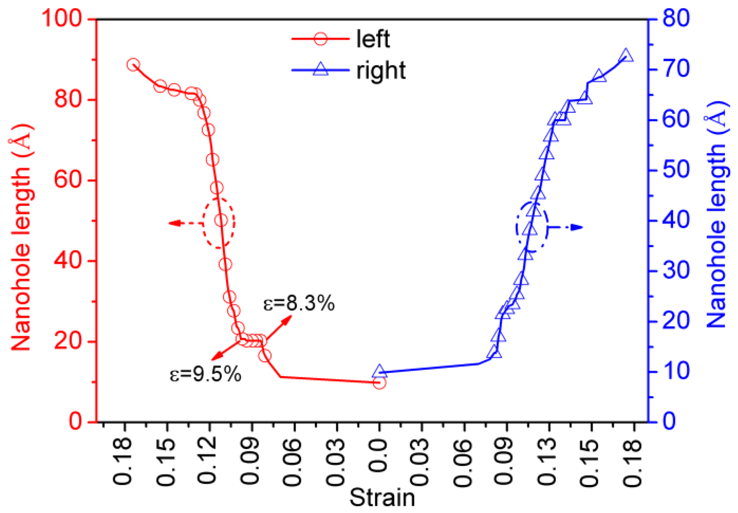
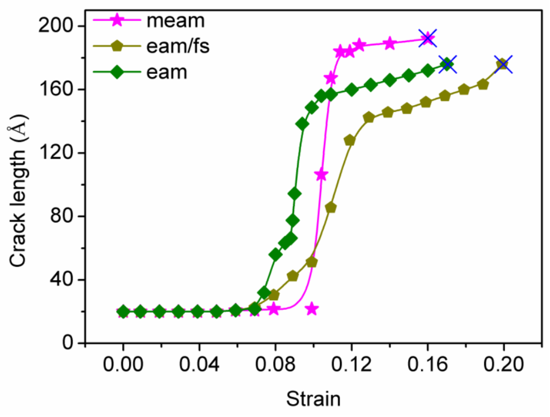
3.3. Relationship between Crack Length and Tensile Strain

Generally, the propagation rate of nanoholes and the flow stress or tensile strains are closely related [50]. Figure 8 shows the relationship between tensile strain and nanohole length for the tensile process of single-crystal Ni at the MEAM, EAM/FS, and EAM potentials. For the MEAM potential, the center nanohole was propagated when the tensile strain was (ε) 10%. After that, the nanohole growth entered a rapid stage—for example, when the tensile strain increased from 10% to 11%, the total nanohole length increased rapidly from 20 Å to 180 Å. Then, the total nanohole length increased slowly. When the tensile strain was ε t 16 % , the nanohole growth extended across the single-crystal Ni along the x-direction (the nanohole length was about 190 Å). The relationship between the nanohole length and strain further confirmed the nature of the nanohole propagation of single-crystal Ni at the MEAM potential. For the single-crystal Ni tensile model under the EAM/FS potential, the central nanohole began to propagate when the tensile strain was (ε) 7% (the single-crystal Ni tensile model under the EAM potential has the same behavior). Then, the tensile models under the EAM/FS and EAM potentials entered the rapid propagation stage. At the strain rates of 10% (for the EAM/FS potential) and 13% (for the EAM potential), the propagation rate of nanoholes decreased. However, in this rapid propagation stage of nanoholes, the nanohole propagation rate of the tensile model under the EAM/FS potential was relatively slow compared to that of the tensile model under the EAM potential. This slow rate was due to the nature of the dislocation (emission and slip) of the tensile model under the EAM/FS potential. Afterward, as the strain increased, the nanohole propagation was conducted in the form of a dislocation moving from the front of the nanohole to the edge of the tensile sample. The relationship between the crack length and strain confirmed the ductile crack propagation of single-crystal Ni at the EAM/FS potential.

3.4. Discussion

Figure 2 and Figure 3 show that the EAM/FS potential was effective in describing the Ni–Ni interaction, which showed good plastic deformation ability and a good maximum cumulative plastic strain ( ε p = 13%). In addition, the cylindrical nanohole first was transformed into a square nanohole due to its good plastic deformation ability before the nanohole propagation. Then, the nanohole was propagated forward due to the local region passivation of the front of the nanohole and the dislocation emission, which showed clear plastic propagation behavior. Therefore, for the single-crystal Ni tensile model under the EAM/FS potential, crack propagation showed the obvious plasticity behavior. For the condition of the MEAM potential to describe the Ni–Ni interaction, the single-crystal Ni showed the worst plastic deformation capacity, and the cumulative plastic strain at the main stage of crack propagation was only about 1% (Figure 4a–h, at which point the crack propagation was almost throughout the entire cross-section of the tensile model). It should be noted that, although the cumulative plastic strain corresponding to this potential was 6% (Figure 3), this was mainly due to the consumption of 5% plastic strain work in the final stage of crack propagation (Figure 4h–g). Hence, when the MEAM potential was used to describe single-crystal Ni, crack propagation showed obvious brittle behavior. For the EAM potential, the single-crystal Ni tensile model exhibited both plastic crack propagation related to dislocations and brittle crack propagation related to the micropore formation (Figure 7e,f). Furthermore, the above analysis can be further confirmed by the results of the crack length and the tensile strain curve in Figure 8.
To analyze the reason for the above difference in nanohole propagation behavior, we further compared the surface energy and stacking fault energy of single-crystal Ni for the MEAM, EAM/FS, and EAM potentials. The surface energy and stacking fault energy are shown in Table 1. It can be found that the model of single-crystal Ni described by the MEAM potential exhibited the maximum surface energy and stacking fault energy. Furthermore, the EAM/FS potential gave the minimum surface energy and stacking fault energy of single-crystal Ni. These differences in surface energy and stacking fault energy of single-crystal Ni at different styles of potentials eventually led to the difference in nanohole propagation behaviors.

4. Conclusions

In this study, based on the MD simulation, we investigated the nanohole propagation behaviors of single-crystal Ni under different styles of potentials (MEAM potential, EAM/FS potential, and EAM potential). The simulation results revealed that the behaviors of nanohole propagation for the different styles of potentials were quite different. According to the experimental results, the following conclusions can be drawn:
(1)
The MEAM potential is best suited to describe the brittle propagation behavior of nanoholes in single-crystal Ni.
(2)
The EAM/FS potential is effective in characterizing the plastic growth behavior of nanoholes in single-crystal Ni.
The results showed the differences between different styles of potentials in characterizing nanohole propagation in single-crystal Ni. Furthermore, the results offer a theoretical basis for the selection of interatomic potentials in the MD simulation of Ni crystals.
However, the current results were obtained under special conditions (for example, a temperature of 20 K and a strain rate of 0.001 ps−1). The microstructure evolution and nanohole propagation process in the single-crystal Ni can be different as the simulation conditions change. In the future, we will systematically consider the effects of temperature, strain rate, crack shape, and potential function on crack propagation in single-crystal Ni.

Supplementary Materials

The following supporting information can be downloaded at: https://www.mdpi.com/article/10.3390/cryst13040585/s1, Table S1. The relevant parameters of the Ni–Ni interatomic meam potential; Table S2. The relevant parameters of the Ni–Ni interatomic eam/fs potential and eam potential;

Author Contributions

Writing—original draft, X.Q.; methodology, Y.L.; visualization, J.G.; software, G.P. All authors have read and agreed to the published version of the manuscript.

Funding

This research was funded by the Engineering Technology Research Center (grant number [2019]5303) and the central government guide’s local science and technology development (grant number [2019]4011).

Data Availability Statement

Not applicable.

Acknowledgments

This work was supported by the Engineering Technology Research Center (Grant NO. [2019]5303) and the central government guide’s local science and technology development (Grant NO. [2019]4011).

Conflicts of Interest

The authors declare no conflict of interest.

References

  1. Proudhon, H.; Li, J.; Wang, F.; Roos, A.; Chiaruttini, V.; Forest, S. 3D simulation of short fatigue crack propagation by finite element crystal plasticity and remeshing. Int. J. Fatigue 2016, 82, 238–246. [Google Scholar] [CrossRef]
  2. Lin, B.; Zhao, L.G.; Tong, J. A crystal plasticity study of cyclic constitutive behavior, crack-tip deformation and crack-growth path for a polycrystalline nickel-based superalloy. Eng. Fract. Mech. 2011, 78, 2174–2192. [Google Scholar] [CrossRef] [Green Version]
  3. Li, L.; Shen, L.; Proust, G. Fatigue crack initiation life prediction for aluminum alloy7075 using crystal plasticity finite element simulations. Mech. Mater. 2015, 81, 84–93. [Google Scholar] [CrossRef]
  4. Yang, S.; Ma, G.; Ren, X.; Ren, F. Cover refinement of numerical manifold method for crack propagation simulation. Eng. Anal. Bound. Elem. 2014, 43, 37–49. [Google Scholar] [CrossRef]
  5. Özden, U.A.; Mingard, K.P.; Zivcec, M.; Bezold, A.; Broeckmann, C. Mesoscopical finite element simulation of fatigue crack propagation in WC/Co-hard metal. Int. J. Refract. Met. Hard Mater. 2015, 49, 261–267. [Google Scholar] [CrossRef]
  6. Dewang, Y.; Hora, M.S.; Panthi, S.K. Prediction of crack location and propagation in stretch flanging process of aluminum alloy AA-5052 sheet using FEM simulation. Trans. Nonferrous Met. Soc. China 2015, 25, 2308–2320. [Google Scholar] [CrossRef]
  7. Özden, U.A.; Bezold, A.; Broeckmann, C. Numerical simulation of fatigue crack propagation in WC/Co based on a continuum damage mechanics approach. Prog. Mater. Sci. 2014, 3, 1518–1523. [Google Scholar] [CrossRef] [Green Version]
  8. Keyhani, A.; Goudarzi, M.; Mohammadi, S.; Roumina, R. XFEM–dislocation dynamics multi-scale modeling of plasticity and fracture. Comput. Mater. Sci. 2015, 104, 98–107. [Google Scholar] [CrossRef]
  9. Calvo, F.; Yurtsever, E. The quantum structure of anionic hydrogen clusters. J. Chem. Phys. 2018, 148, 102305. [Google Scholar] [CrossRef] [Green Version]
  10. Hou, Y.; Wang, L.; Wang, D.; Qu, X.; Wu, J. Using a molecular dynamics simulation to investigate asphalt nano-cracking under external loading conditions. Appl. Sci. 2017, 7, 770. [Google Scholar] [CrossRef] [Green Version]
  11. Ramezani, M.G.; Golchinfar, B. Mechanical properties of cellulose nanocrystal (CNC) bundles: Coarse-grained molecular dynamic simulation. J. Compos. Sci. 2019, 3, 57. [Google Scholar] [CrossRef] [Green Version]
  12. Liu, C.; Yao, Y. Study of crack-propagation mechanism of Al0.1CoCrFeNi high-entropy alloy by molecular dynamics method. Crystals 2023, 13, 11. [Google Scholar] [CrossRef]
  13. Lee, S.; Kang, H.; Bae, D. Molecular dynamics study on crack propagation in Al containing Mg–Si clusters formed during natural aging. Materials 2023, 16, 883. [Google Scholar] [CrossRef] [PubMed]
  14. Komanduri, R.; Chandrasekaran, N.; Raff, L.M. Molecular dynamics (MD) simulation of uniaxial tensile of some single-crystal cubic metals at nanolevel. Int. J. Mech. Sci. 2001, 43, 2237–2260. [Google Scholar] [CrossRef]
  15. Xu, S.; Deng, X. Nanoscale void nucleation and growth and crack tip stress evolution ahead of a growing crack in a single crystal. Nanotechnology 2008, 19, 115705. [Google Scholar] [CrossRef]
  16. Cui, C.B.; Beom, H.G. Molecular dynamics simulations of edge cracks in copper and aluminum single crystals. Mater. Sci. Eng. A 2014, 15, 102–109. [Google Scholar] [CrossRef]
  17. Zhuo, X.R.; Kim, J.H.; Gyu Beom, H. Atomistic investigation of crack growth resistance in a single-crystal Al-nanoplate. J. Mater. Res. 2016, 9, 1185–1192. [Google Scholar] [CrossRef]
  18. Ding, J.; Wang, L.-S.; Song, K.; Liu, B.; Huang, X. Molecular dynamics simulation of crack propagation in single-crystal Aluminum plate with central cracks. J. Nanomater. 2017, 2017, 5181206. [Google Scholar] [CrossRef] [Green Version]
  19. Mikelani, M.; Panjepour, M.; Taherizadeh, A. Investigation on mechanical properties of nanofoam aluminum single crystal: Using the method of molecular dynamics simulation. Appl. Phys. A Mater. Sci. Process. 2020, 126, 921. [Google Scholar] [CrossRef]
  20. Ji, H.; Ren, K.; Ding, L.; Wang, T.; Li, J.-M.; Yang, J. Molecular dynamics simulation of the interaction between cracks in single crystal Aluminum. Mater. Today Commun. 2022, 30, 103020. [Google Scholar] [CrossRef]
  21. Yu, J.; Zhang, Q.; Liu, R.; Yue, Z.; Tang, M.; Li, X. Molecular dynamics simulation of crack propagation behaviors at the Ni/Ni3Al grain boundary. RSC Adv. 2014, 4, 32749. [Google Scholar] [CrossRef]
  22. Hou, N.X.; Wen, Z.X.; Yue, Z.F. Creep behavior of single crystal superalloy specimen under temperature gradient condition. Mater. Sci. Eng. A 2009, 510–511, 42–45. [Google Scholar] [CrossRef]
  23. Mao, H.; Wen, Z.; Yue, Z.; Wang, B. The evolution of plasticity for nickel-base single crystal cooled blade with film cooling holes. Mater. Sci. Eng. A 2013, 587, 79–84. [Google Scholar] [CrossRef]
  24. Kim, J.; Suh, C.; Amanov, A.; Kim, H.; Pyun, Y. Rotary bending fatigue properties of Inconel 718 alloys by ultrasonic nanocrystal surface modification technique. J. Eng. 2015, 13, 133–137. [Google Scholar] [CrossRef]
  25. Yang, X.F.; He, C.Y.; Yuan, G.J.; Chen, H.; Wang, R.Z.; Jia, Y.F.; Tu, S.T. The effects of grain boundary structures on crack nucleation in nickel nanolaminsted structure: A molecular dynamics study. Comput. Mater. Sci. 2021, 186, 110019. [Google Scholar] [CrossRef]
  26. Mishin, Y.; Farkas, D.; Mehl, M.J.; Papaconstantopoulos, D.A. Interatomic potentials for monatomic metals from experimental data and ab initio calculations. Phys. Rev. B 1999, 59, 3393–3407. [Google Scholar] [CrossRef] [Green Version]
  27. Wu, W.-P.; Yao, Z.-Z. Molecular dynamics simulation of stress distribution and microstructure evolution ahead of a growing crack in single crystal nickel. Theor. Appl. Fract. Mech. 2012, 62, 67–75. [Google Scholar] [CrossRef]
  28. Sung, P.-H.; Chen, T.-C. Studies of crack growth and propagation of single-crystal nickel by molecular dynamics. Comput. Mater. Sci. 2015, 102, 151–158. [Google Scholar] [CrossRef]
  29. Ma, L.; Xiao, S.; Deng, H.; Hu, W. Atomistic simulation of mechanical properties and crack propagation on irradiated nickel. Comput. Mater. Sci. 2016, 120, 21–28. [Google Scholar] [CrossRef]
  30. Zhang, Y.; Jiang, S. Molecular dynamics simulation of crack propagation in nanoscale polycrystal nickel based on different strain rate. Metal 2017, 7, 432. [Google Scholar] [CrossRef] [Green Version]
  31. Zhang, Y.; Jiang, S.; Zhu, X.; Zhao, Y. Mechanisms of crack propagation in nanoscale single crystal, bicrystal and tricrystal nickels based on the molecular dynamics simulation. Results Phys. 2017, 7, 1722–1733. [Google Scholar] [CrossRef]
  32. Zhang, Y.; Jiang, S. Investigation on dislocation-based mechanisms of void growth and coalescence on single and nanotwinned nickels by molecular dynamics simulation. Philos. Mag. 2017, 97, 2772–2794. [Google Scholar] [CrossRef]
  33. Zhang, Y.; Jiang, S.; Zhu, X.; Zhao, Y. A molecular dynamics study of intercrystalline crack propagation in nano-nickel bicrystal films with (010) twist boundary. Eng. Fract. Mech. 2016, 168, 147–159. [Google Scholar] [CrossRef]
  34. Zhang, Y.; Jiang, S.; Zhu, X.; Zhao, Y. Influence of twist angle on crack propagation of nanoscale bicrystal nickel film based on molecular dynamics simulation. Phys. E Low-Dimens. Syst. Nanostruct. 2017, 87, 281–294. [Google Scholar] [CrossRef]
  35. Zhang, J.; Ghosh, S. Molecular dynamics based study and characterization of deformation mechanisms near a crack in a crystalline material. J. Mech. Phys. Solids 2013, 61, 1670–1690. [Google Scholar] [CrossRef]
  36. Glenn, J.; Martyna, D.J.; Tobias, M.L. Klein. Constant pressure molecular dynamics algorithms. J. Chem. Phys. 1994, 101, 4177–4189. [Google Scholar]
  37. Parrinello, M.; Rahman, A. Polymorphic transitions in single crystal: A new molecular dynamics method. J. Appl. Phys. 1981, 52, 7182–7190. [Google Scholar] [CrossRef]
  38. Tuckerman, M.E.; Alejandre, J.; López-Rendón, R.; Jochim, A.L.; Martyna, G.J. A Liouville-operator derived measure-preserving integrator for molecular dynamics simulations in the isothermal–isobaric ensemble. J. Phys. A Math. Gen. 2006, 39, 5629–5651. [Google Scholar] [CrossRef]
  39. Stukowski, A. Visualization and analysis of atomistic simulation data with OVITO—The open visualization tool. Model. Simul. Mater. Sci. Eng. 2010, 18, 015012. [Google Scholar] [CrossRef]
  40. Heyes, D.M. Pressure tensor of partial-charge and point-dipole lattices with bulk and surface geometries. Phys. Rev. B 1994, 49, 755–764. [Google Scholar] [CrossRef]
  41. Sirk, T.W.; Moore, S.; Brown, E.F. Characteristics of thermal conductivity in classical water models. J. Chem. Phys. 2013, 138, 064505. [Google Scholar] [CrossRef] [PubMed]
  42. Aidan, P.; Thompson, S.J.; Plimpton, W.M. General formation of pressure and stress tensor for arbitrary many-body interaction potentials under periodic boundary conditions. J. Chem. Phys. 2009, 131, 154107. [Google Scholar]
  43. Honeycutt, J.D.; Andersen, H.C. Andersen. Molecular dynamics study of melting and freezing of small Lennard-Jones clusters. J. Phys. Chem. 1987, 91, 4950–4963. [Google Scholar] [CrossRef]
  44. Faken, D.; Jónsson, H. Systematic analysis of local atomic structure combined with 3D computer graphics. Comput. Mater. Sci. 1994, 2, 279–286. [Google Scholar] [CrossRef]
  45. Lee, B.-J.; Shim, J.-H.; Baskes, M.I. Semiempirical atomic potentials for the fcc metals Cu, Ag, Au, Ni, Pd, Pt, Al, and Pb based on first and second nearest-neighbor modified embedded atom method. Phys. Rev. B 2003, 68, 144112. [Google Scholar] [CrossRef]
  46. Ackland, G.J.; Tichy, G.; Vitek, V.; Finnis, M.W. Simple N-body potentials for the noble metals and nickel. Philos. Mag. A 1987, 56, 735–756. [Google Scholar] [CrossRef]
  47. Foiles, S.M.; Baskes, M.I.; Daw, M.S. Embedded-atom-method functions for the fcc metals Cu, Ag, Au, Ni, Pd, Pt, and their alloys. Phys. Rev. B 1986, 33, 7983–7991. [Google Scholar] [CrossRef]
  48. Sainath, G.; Choudhary, B.K. Atomistic simulations on ductile-brittle transition in <111> BCC Fe nanowires. J. Appl. Phys. 2017, 122, 095101. [Google Scholar]
  49. Gordon, P.A.; Neeraj, T.; Luton, M.J.; Farkas, D. Crack-tip deformation mechanisms in α-Fe and binary Fe alloys: An atomistic study on single crystals. Metall. Mater. Trans. A 2007, 38A, 2191–2202. [Google Scholar] [CrossRef]
  50. Sainath, G.; Nagesha, A. Atomistic simulations of twin boundary effect on the crack growth behavior in BCC Fe. Trans. Indian Natl. Acad. Eng. 2022, 7, 433–439. [Google Scholar] [CrossRef]
Figure 1. The MD model of FCC single-crystal Ni with a central cylindrical nanohole: (a) the size and orientation of simulated region and (b) single-crystal Ni with cylindrical nanohole.
Crystals 13 00585 g001
Figure 2. The stress–strain behavior of single-crystal Ni under the (a) MEAM potential, (b) EAM/FS potential, and (c) EAM potential. The failure location is marked by the solid arrow.
Crystals 13 00585 g002
Figure 3. The elastic strain ε e , total strain ε t and accumulated plastic strain ε p of single-crystal Ni under different styles of interatomic potentials.
Crystals 13 00585 g003
Figure 4. The contour plots of the atomic tensile stress field and nanohole growth states at different tensile strains (MEAM potential).
Crystals 13 00585 g004
Figure 5. The contour plots of the atomic tensile stress field and crack growth states at different tensile strains (EAM/FS potential).
Crystals 13 00585 g005
Figure 6. The nanohole length–strain curve of the nanohole propagation process (EAM/FS potential).
Crystals 13 00585 g006
Figure 7. The contour plots of the atomic tensile field and crack growth states at different tensile strains (EAM potential).
Crystals 13 00585 g007
Figure 8. The crack length–strain curve of single-crystal Ni at different styles of potentials. The symbol ‘×’ denotes the fracture point of the tensile model.
Crystals 13 00585 g008
Table 1. The computed properties of single-crystal Ni for the different styles of potentials.
MEAMEAM/FSEAM
Surface energy (erg/cm2)(100) plane194314441580
(110) plane205715481730
(111) plane160611531450
Stacking fault energy (erg/cm2)12533--
Disclaimer/Publisher’s Note: The statements, opinions and data contained in all publications are solely those of the individual author(s) and contributor(s) and not of MDPI and/or the editor(s). MDPI and/or the editor(s) disclaim responsibility for any injury to people or property resulting from any ideas, methods, instructions or products referred to in the content.

