Article

Effects of Crack Formation on the Mechanical Properties of Bilayer Graphene: A Comparative Analysis

1
School of Science, Harbin Institute of Technology (Shenzhen), Shenzhen 518055, China
2
School of Materials Science and Physics, China University of Mining and Technology, Xuzhou 221116, China
3
State Key Laboratory of Nonlinear Mechanics, Institute of Mechanics, Chinese Academy of Sciences, Beijing 100190, China
4
School of Engineering Sciences, University of Chinese Academy of Sciences, Beijing 100049, China
*
Author to whom correspondence should be addressed.
Crystals 2023, 13(4), 584; https://doi.org/10.3390/cryst13040584
Submission received: 28 February 2023 / Revised: 21 March 2023 / Accepted: 24 March 2023 / Published: 29 March 2023
(This article belongs to the Section Inorganic Crystalline Materials)

Abstract

:
We present a molecular dynamics simulation study on the effects of crack formation on the mechanical properties of bilayer graphene. Bilayer graphene possesses unique electronic properties that can be modified by applying a voltage, making it an attractive material for various applications. We examined how the mechanical properties of bilayer graphene vary under various crack configurations and temperatures, measuring Young’s modulus, fracture toughness, fracture strain, and fracture stress. We compared the effect of crack presence on single and both layers and found the appearance of double peaks in the stress–strain curves in the case of a monolayer crack, indicating a subsequent fracture of the cracked layer and the uncracked layer. We also examined the effect of crack shape, size, and orientation on mechanical properties, including circular, hexagonal, and rectangular cracks along two axes. We found that both circular and hexagonal cracks had a smaller Young’s modulus and toughness than rectangular cracks, and the orientation of the crack had a significant impact on the mechanical properties, with a 2.5-times higher toughness for cracks with a length of 15 Å . Additionally, we found that Young’s modulus decreases with increasing temperature in bilayer graphene with cracks on both layers. Our findings provide valuable insights into the potential applications of bilayer graphene in the design of advanced nanoscale electronic devices.

1. Introduction

Since the discovery of graphene by the K.S. Novoselov and A.K. Geim group [1], graphene has been extensively researched and pursued as a new carbon-based material with a honeycomb 2D lattice structure and exceptional mechanical properties [2,3,4,5,6,7,8,9]. It is considered to be one of the strongest materials [10,11] and is widely used in fields such as electronics, thermology, etc. [12,13,14]. Its typical properties have also inspired the study of other materials to seek new materials generated by 2D effects [9]. Among the many graphene-related materials, bilayer graphene is one of the most interesting materials [15]. Bilayer graphene is a two-dimensional material consisting of two layers of graphene arranged in a Bernal stacking configuration [16]. The two layers are held together by weak van der Waals forces, which results in unique properties that differ from those of single-layer graphene.
One notable property of bilayer graphene is its electronic structure [17]. Unlike single-layer graphene, bilayer graphene has a bandgap that can be tuned by applying an electric field perpendicular to the layers. This property makes bilayer graphene promising for use in electronic devices, such as transistors and photodetectors [18,19,20,21,22]. Another important property of bilayer graphene is its mechanical strength [23]. The van der Waals forces between the layers make bilayer graphene more flexible than single-layer graphene, while still maintaining its strength. This property makes bilayer graphene a promising material for applications that require both strength and flexibility, such as in the construction of sensors and membranes [24,25].
Bilayer graphene exhibits unique mechanical properties that are influenced by various factors [26,27,28,29]. Temperature plays a crucial role in determining the mechanical properties of multilayer graphene [30]. Previous research shows that Young’s modulus decreases linearly with strain in bilayer graphene, while Poisson’s ratio is independent of the strain [31]. The elastic stiffness of the graphene can be significantly deteriorated under shear stress by the presence of vacancy defects [32]. The hardness of graphene has a linear relationship with the number of layers [33], and the binding strength between adjacent layers increases with the number of graphene layers. Overall, the mechanical properties of bilayer graphene are influenced by various factors [34], including temperature, defects, and crystal fields, and understanding these factors is essential for designing and optimizing graphene-based materials for a range of applications [35,36,37,38].
In this article, we present a molecular dynamics simulation study on the effects of crack formation on the mechanical properties of bilayer graphene. We examined how the mechanical properties of the bilayer graphene vary under various crack configurations and temperatures, measuring Young’s modulus, fracture toughness, fracture strain, and fracture stress. We examined how the crack shape, size, and orientation affect the mechanical properties, including circular and rectangular cracks along two axes. Our findings showed that the bilayer graphene with circular cracks had a smaller Young’s modulus and toughness than that with the same size of rectangular cracks, and the orientation of the crack had a significant impact on the mechanical properties. Additionally, we also found that Young’s modulus decreases with an increasing temperature in bilayer graphene with cracks on both layers Our findings provide valuable insights into the potential applications of bilayer graphene in the design of advanced nanoscale electronic devices.
The discussion is structured into three sections. Section 2 provides a detailed overview of the methodology used in the study, including the computational techniques and parameters employed. In Section 3, we examine the impact of different factors on the mechanics of bilayer graphene, including rectangular cracks with various orientations, circular cracks, and hexagonal cracks. Specifically, we analyze the behavior of bilayer graphene with monolayer cracks and bilayer cracks. Finally, in Section 4, we summarize our findings and provide a conclusion, highlighting the key insights from our investigation and their potential implications for future research.

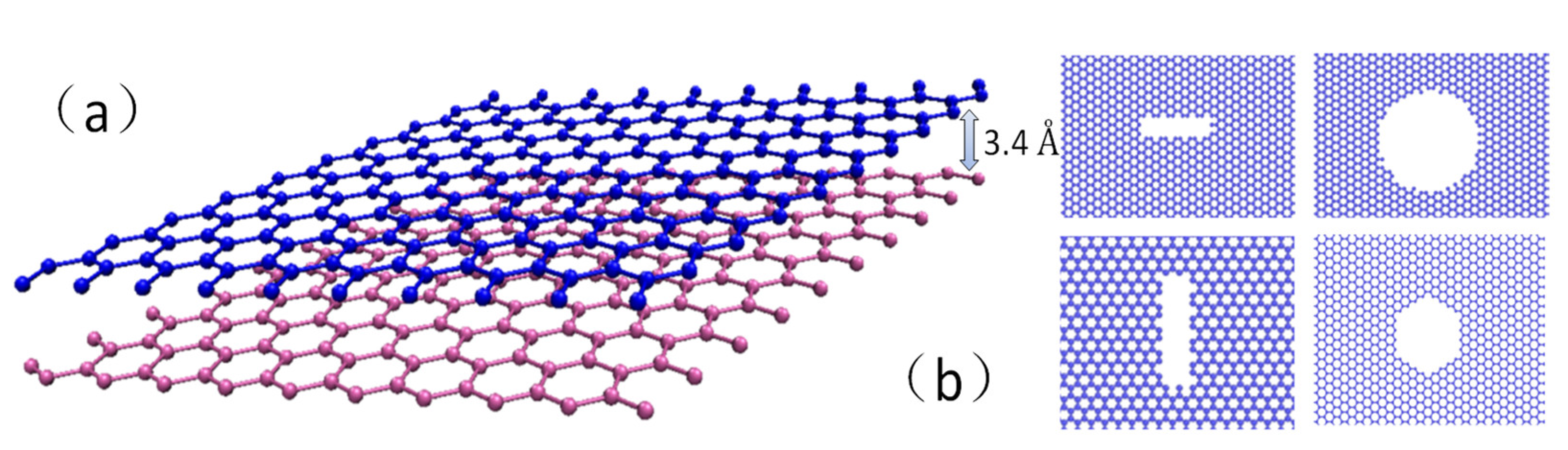
2. Materials and Methods

We employed molecular dynamics simulations in this study, with the developed software of LAMMPS (large-scale atomic/molecular massively parallel simulator) [39]. OVITO (open visualization tool) [40] and VMD (visual molecular dynamics) [41] were utilized to generate the atomistic simulation results and figures. The adaptive intermolecular reactive bond order (AIREBO) [42] was chosen as the force field that can describe the interactions between carbon atoms. The AIREBO potentials were modified for the carbon nanostructures with significant deformation. We set Rmin = 2.0 Å to account for the overestimation of nanostructure strength near the fracture stage [43]. For the interlayer van der Waals (vdW) interaction, we use the Lennard–Jones potentials that are consistent with past research [44].
The simulation model of bilayer graphene was established as shown in Figure 1, with a C–C bond length of 0.142 nm within a layer and an interlayer distance of 3.4 Å. All simulations were conducted at 300 K, using a simulation time step of 0.001 picoseconds (ps). The size of the equilibrated simulation box was 30 × 5 × 6.7 Å3, containing 11,928 atoms, where the size effect would be studied in the next section.
The Young’s modulus E, fracture stress σ c , and fracture strain εF were obtained from the simulated stress–strain curves. Young’s modulus was calculated as the initial slope of the stress–strain curve, while the fracture stress and fracture strain were defined at the point where the peak stress was reached. The toughness is defined as the area under the curve from the origin (0,0) to the point of fracture. The toughness is also the amount of energy that a material can absorb before fracturing, and it is proportional to the area under the stress–strain curve.
In the precrack system, different shapes and sizes of “cracks” were generated by removing atoms near the center of the simulation box, as depicted in Figure 1b. When subjected to a tensile load, the occurrence of brittle fracture according to Griffith’s theory can be determined through lattice crack propagation simulations in the material. Our results are consistent with the experimental observation of brittle fracture in the graphene [45]. In addition, Griffith’s theory suggests that the brittle fracture of a material is caused by the presence of preexisting flaws or cracks within the material. These flaws act as stress concentrations, leading to a significantly higher stress at the tip of the crack than the average stress applied to the material. If the stress at the crack tip exceeds a critical value, known as the fracture toughness, the crack will propagate, and the material will fracture suddenly and catastrophically.
Griffith’s brittle fracture criteria can be mathematically expressed as follows:
σ c = 2 γ E π a 0
Here, σ c represents the fracture stress, γ represents the material’s surface energy, E represents Young’s modulus of elasticity, and a 0 represents the length of the flaw or crack. This model is commonly utilized to analyze the fracture behavior of brittle materials such as ceramics, glasses, and some polymers. It has been widely used in the development of new materials and in the design of structures to prevent brittle fractures.

3. Results and Discussion

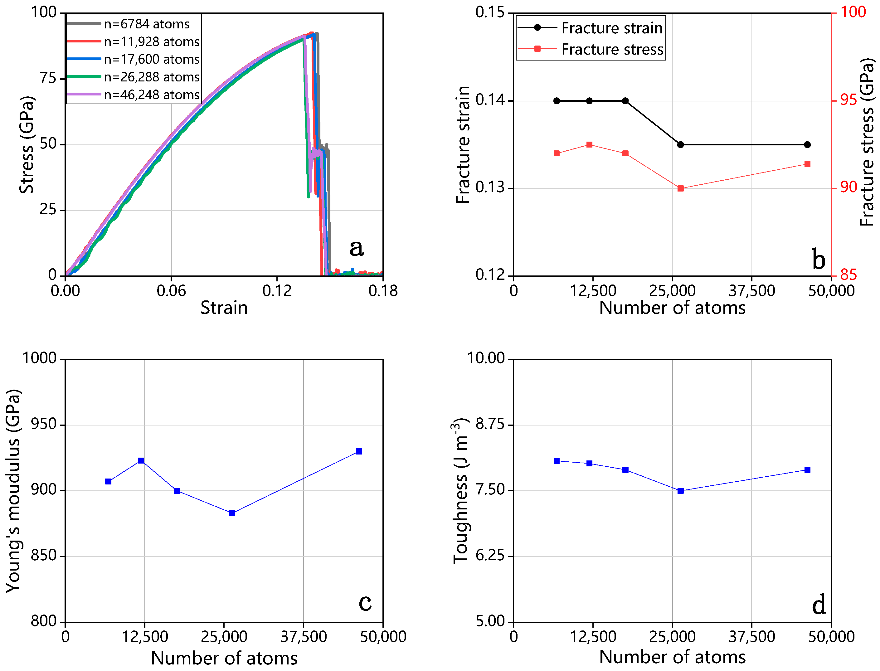
3.1. Effect of the System Size

The selection of an appropriate number of atoms is essential for simulating a material system to obtain a converged result. An excessive number of atoms in the calculation model may increase the computational burden, while an inadequate number may fail to capture the material’s properties adequately. Thus, we conducted a thorough analysis of the influence of the number of atoms on the mechanical properties of bilayer graphene. The results, as depicted in Figure 2, indicate that the difference in stress–strain behavior diminishes with an increase in the number of atoms, suggesting that the number of atoms has a relatively small impact on stress–strain behavior. Furthermore, the maximum and minimum fracture stresses observed at the point of failure are 92.5 GPa and 90 GPa, respectively, corresponding to 11,928 atoms and 26,288 atoms, respectively, with a difference of only 2.5 GPa. Similarly, the difference in strain between the maximum and minimum is merely 0.005. Additionally, we investigated the effect of the number of atoms on Young’s modulus and toughness, as shown in Figure 2c,d, respectively. The results reveal that Young’s modulus increases, decreases, and then increases again with a maximum difference of 47 GPa, observed between 930 GPa (corresponding to 46,248 atoms) and 883 GPa (corresponding to 26,288 atoms). The effect of the number of atoms on the toughness is negligible, with a difference of only 0.5 between the maximum and minimum values. Overall, the variation in the number of atoms has a limited impact on the mechanical properties of bilayer graphene, so we selected 11,928 atoms for our study. The stress–strain behavior was found to be consistent across the different pressure conditions (0 to 3 atm). Therefore, subsequent investigations into the mechanical properties of bilayer graphene were conducted under 0 atm conditions for convenience and consistency.

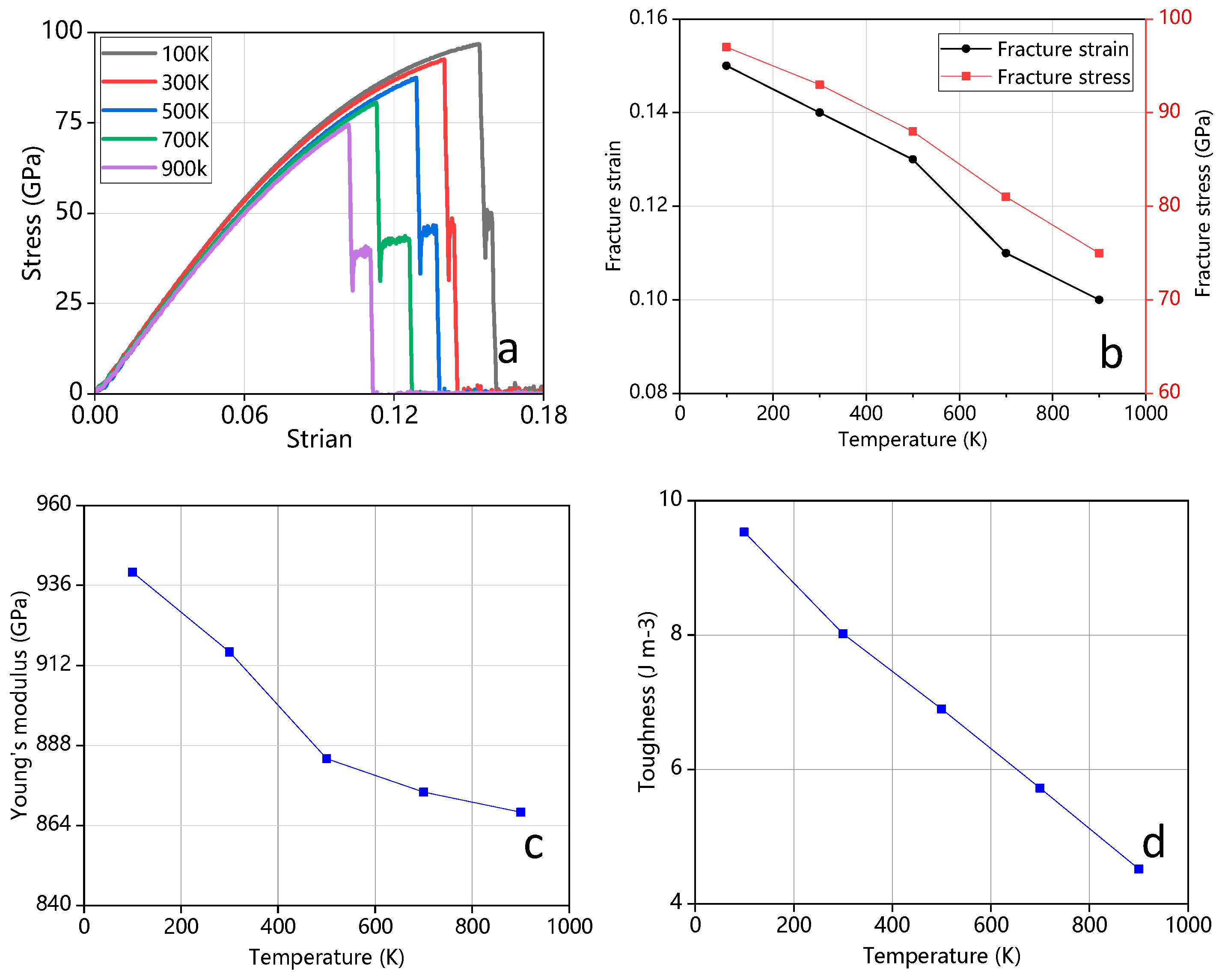
3.2. Effect of Temperature

The impact of temperature on the mechanical properties of materials is significant. To investigate the influence of temperature on bilayer graphene, a temperature range of 100 K to 900 K was selected for analysis. As depicted in Figure 3, under unchanged experimental conditions, the stress–strain behavior of graphene decreased with an increasing temperature. The corresponding fracture strain and stress also decreased, as shown in Figure 3b. The Young’s modulus of the bilayer graphene also exhibited a decreasing trend with an increase in temperature, as depicted in Figure 3c. The increase in temperature leads to an increase in the internal energy of the atoms, making the material more susceptible to fracture and instability [46]. Furthermore, the fracture toughness of the material showed a linear decrease with increasing temperature, as illustrated in Figure 3d.

3.3. Bilayer Graphene with Cracks on Both Layers

To further investigate the mechanical properties of bilayer graphene with cracks, we conducted separate studies on bilayer graphene with cracks on both layers (results presented in Section 3.3), and on monolayer graphene (results presented in Section 3.4). Specifically, we examined rectangular cracks (with lengths ranging from 5 to 20 Å along the x and y axes and a width of 4 Å), circular cracks (with diameters ranging from 5 to 15 Å) in the bilayer graphene, and compared their mechanical properties (discussed in Section 3.5). We also analyzed symmetrical hexagonal cracks in the bilayer graphene with apex distances ranging from 7.38 Å to 22.14 Å (discussed in Section 3.3.3)

3.3.1. Rectangular Cracks

When the rectangular crack is oriented in the y-direction. As the length of the rectangle increases, the change trend of the stress–strain curve is basically the same, however, the strain and stress at the fracture both decrease, which indicates that the tensile capacity of graphene decreases with the increase of the crack length (as shown in Figure 4a). The decrease in the stress–strain curve can be attributed to the reduced area of graphene that connects the two sides of the crack, resulting in a decrease in the structural strength and an increase in the likelihood of fracture. The fracture strain and stress also decrease as the length of the crack increases (as shown in Figure 4c). Moreover, Young’s modulus and toughness also decrease continuously with increasing crack length.
In contrast to the behavior observed in the crack oriented in the y-direction, the stress–strain response of bilayer graphene with rectangular cracks oriented in the x-direction shows an increase in stress and strain with an increase in crack length (as shown in Figure 4b). Interestingly, the fracture stress and strain also increase simultaneously (as shown in Figure 4f), while Young’s modulus decreases (as shown in Figure 4g). This indicates that, as the length of the rectangular crack increases, the material becomes more ductile and less prone to fracture. This behavior is attributed to the fact that the stress and strain gradients in this direction are smaller, resulting in lower stress at the crack tip and, consequently, less energy required for crack propagation. Additionally, when the crack is parallel to the direction of the strain, the crack propagation path is restricted, making it more difficult for the crack to propagate than in the case where the crack is perpendicular to the direction of strain, thus requiring greater stress concentration at the crack tip for propagation.
In Figure 5, we compared the stress–strain behaviors of cracks with the same length but different orientations. We found that the stress–strain curves of the rectangular cracks in the x direction are significantly higher than those in the y direction. Moreover, Table 1 shows that the rectangular cracks in the x direction have a higher fracture stress and strain, higher Young’s modulus, and almost three times higher toughness than those in the y direction. These findings suggest that the orientation of the crack plays a crucial role in determining the mechanical properties of bilayer graphene.

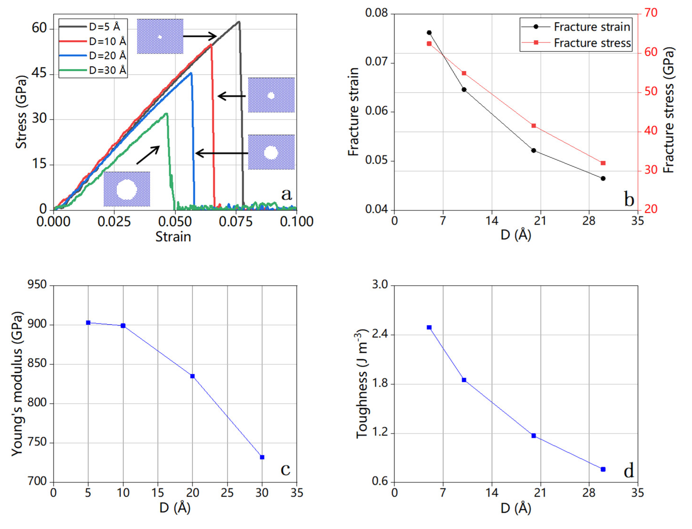
3.3.2. Circular Cracks

Circular cracks were selected as another type of crack shape in our study. As the diameter of the circular crack increases, the change trend of the stress–strain curve is basically the same, however, the strain and stress at the fracture both decrease, which indicates that the tensile capacity of graphene decreases with the increase of the diameter of the circular crack (as shown in Figure 6a). The corresponding fracture stress–strain (as shown in Figure 6b), Young’s modulus (as shown in Figure 6c), and toughness (as shown in Figure 6d) also decrease with the increasing diameter of the cracks.

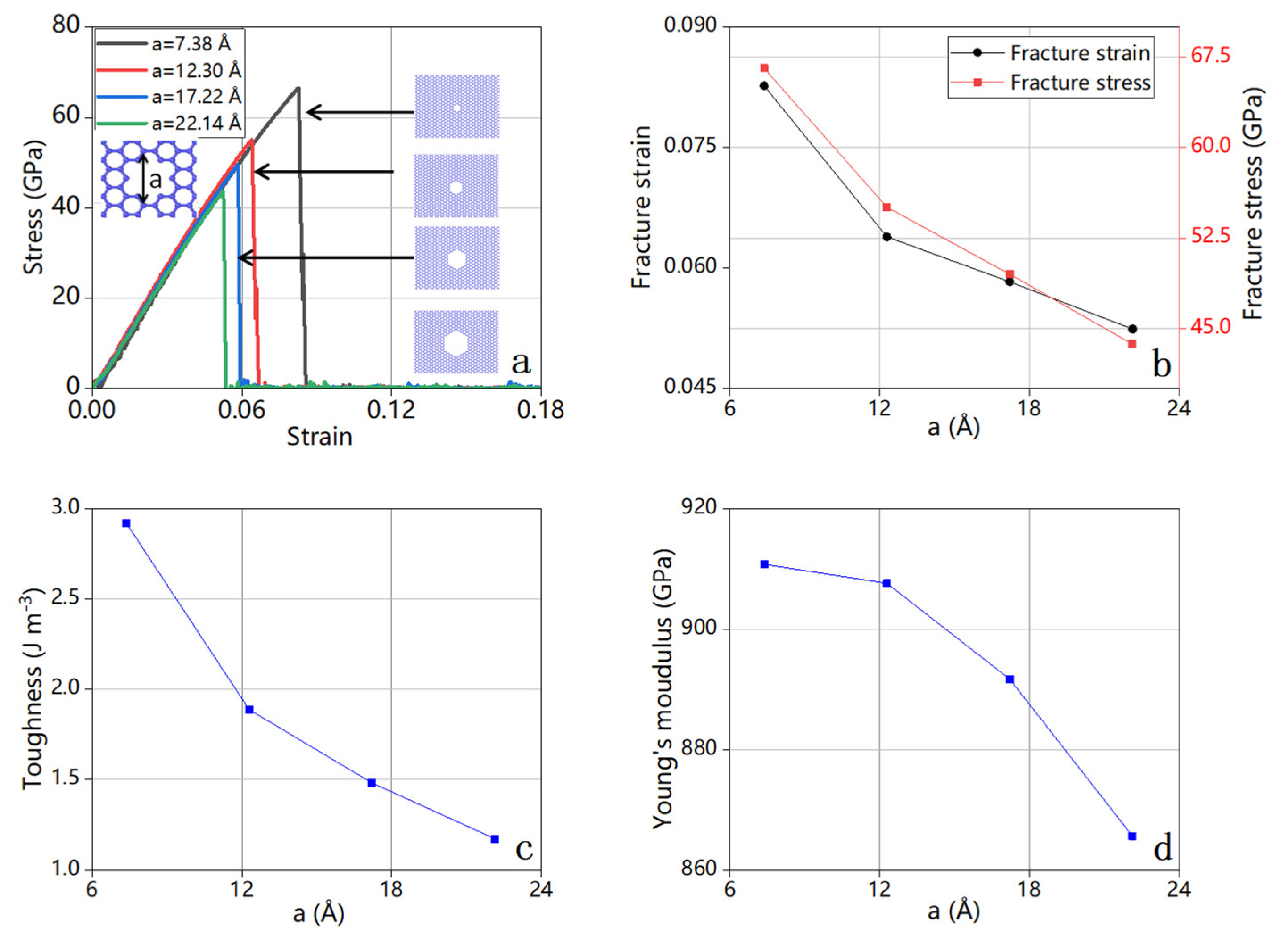
3.3.3. Quasi-Hexagonal Cracks and Compare with Circular Cracks

We obtained a quasi-hexagonal symmetric structure by deleting graphene atoms and selected four kinds of maximum vertex distances of 7.38 to 22.14 Å to analyze the influence of symmetric structure cracks on the mechanical properties of bilayer graphene. From Figure 7a we can see, similar to the previous circular crack, the stress–strain at fracture decreases as the crack increases, which is more prominent in Figure 7b, while Young’s modulus (Figure 7c) and toughness (such as Figure 7d) is also decreasing with the increase in cracks. Therefore, the symmetrical structures, including circular and quasi-hexagonal cracks, have basically the same effect on the mechanical properties of bilayer graphene.

3.3.4. Comparison of Bilayer Circular Cracks and Quasi-Hexagonal Cracks

In order to compare the effects of regular hexagonal and circular cracks on the mechanical properties of bilayer graphene, we selected the diameter of the circular crack (D = 22.14 Å) and the distance from the farthest vertex of the quasi-regular hexagon (a = 22.14 Å) stress–strain. The curve is shown in Figure 8. It can be seen from the figure that the stress and strain of the same two-layer graphene are basically the same when the double-layer graphene is broken. Other mechanical data, such as Young’s modulus and fracture toughness, show that, although there is a gap, the difference is not much different where Young’s modulus of the hexagonal cracks is larger than that of circular cracks. We believe that it is caused by the different crack areas. Under the same crack length, the circular cracks form a larger crack area, which makes graphene stretch. It is easier to be broken, and the stress at the ductile fracture is also smaller, which is more obvious in Table 2 and Table 3. Based on the simulation results, we believe that the crack area of the symmetrical structure is the main reason affecting the mechanical properties of the material. In practice, care should be taken to prevent the crack area from increasing so as not to affect the mechanical properties of the material.

3.4. Bilayer Graphene with Cracks on Single Layer

In this section, we investigate the possibility of having cracks in only one layer of bilayer graphene with different crack shapes. To this end, we consider rectangular and circular cracks in a single layer. The aim of this discussion is to further explore how the crack geometry alters the mechanical properties in the system.

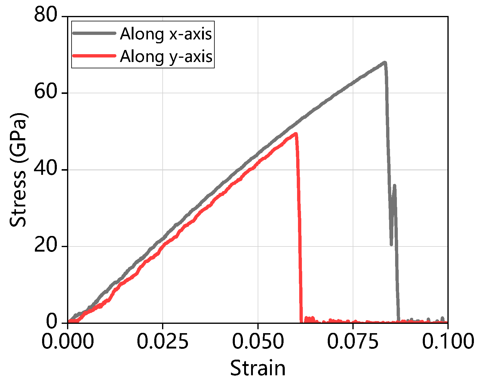
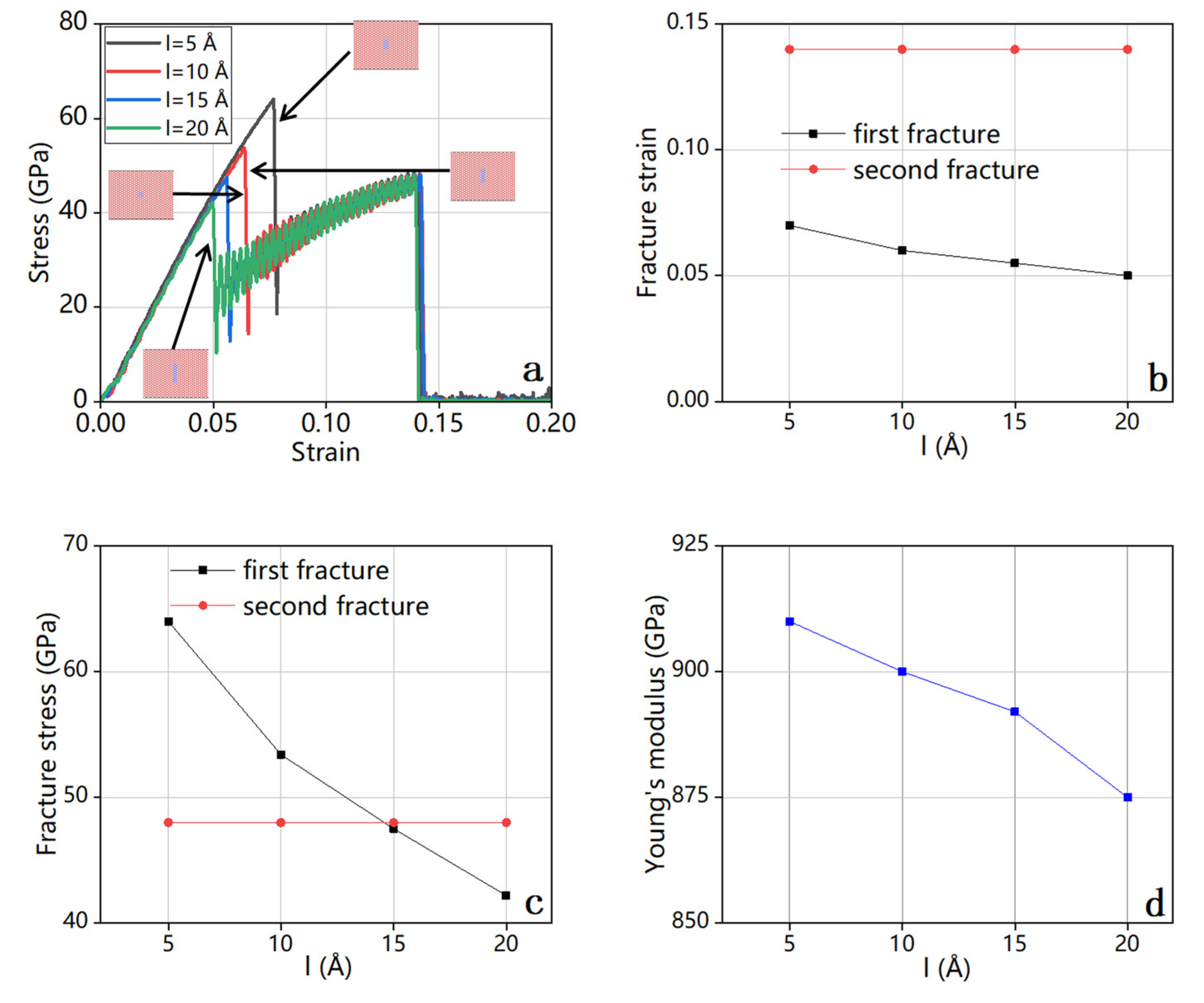
3.4.1. Rectangular Cracks (Along y-Axis)

The stress–strain curve of bilayer graphene with single-layer cracks in Figure 9a displays a distinct double fracture behavior, unlike the one with cracks on both layers. The reason behind this is that when a single layer of the bilayer graphene contains cracks, the layer with cracks fractures first, followed by the layer without cracks, resulting in two consecutive fractures. We observed a continuous decrease in stress and strain as the length of the crack increased. Figure 9b,c shows that the stress and strain did not change during the second fracture. Additionally, fracture stress and strain during the first fracture decreased as the length of the rectangular crack increased. Figure 9d shows that Young’s modulus also decreased with an increasing rectangular crack length.

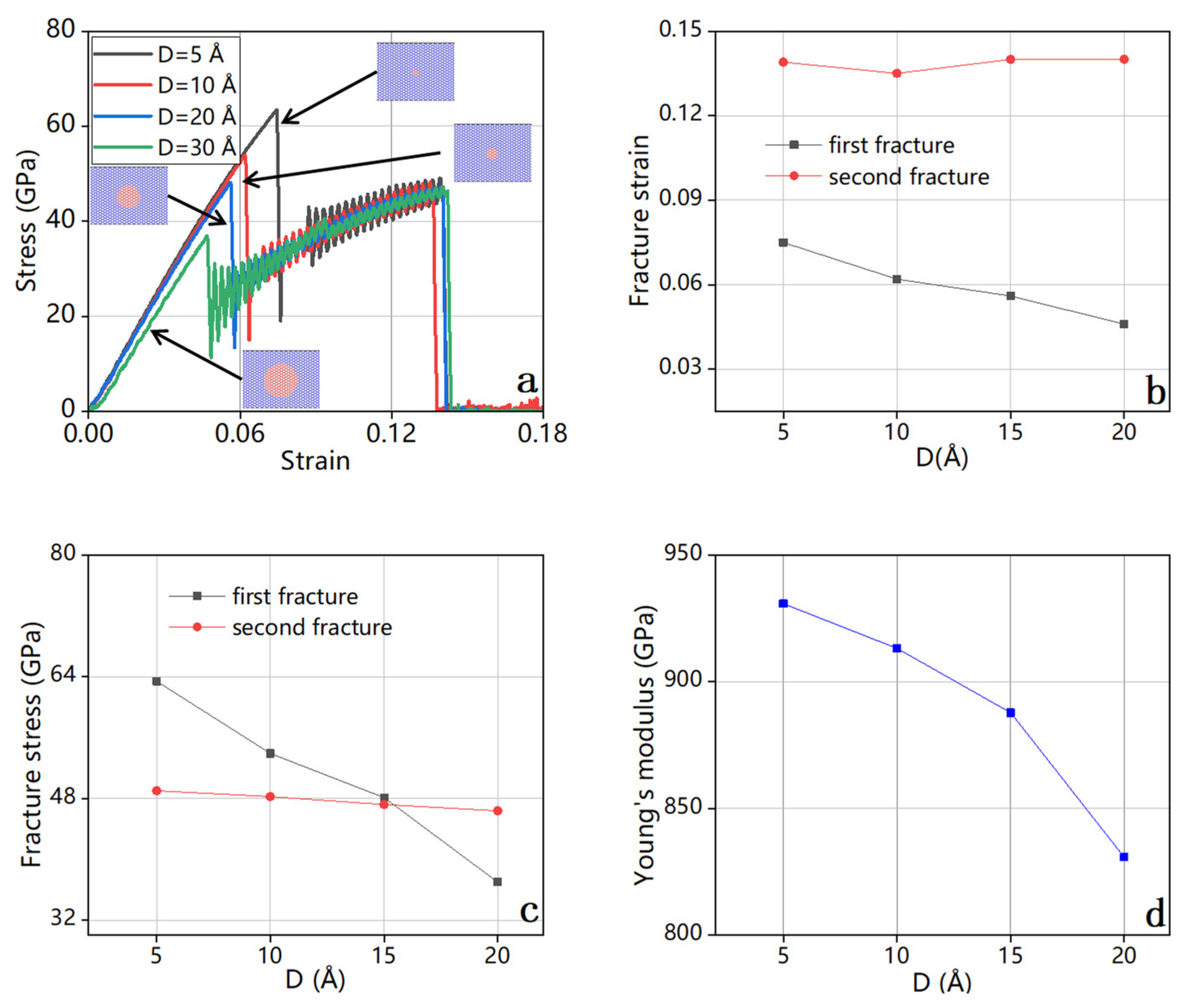
3.4.2. Circular Cracks

Similar to the case with rectangular cracks, bilayer graphene with circular cracks on a single layer displays a secondary fracture, as illustrated by the stress–strain curve in Figure 10a. The subsequent stress–strain curves of the secondary fracture (depicted in Figure 10b,c) exhibit a gradual decrease in Young’s modulus (Figure 10d), indicating a decline in bilayer graphene’s stiffness caused by the presence of single-layer cracks.

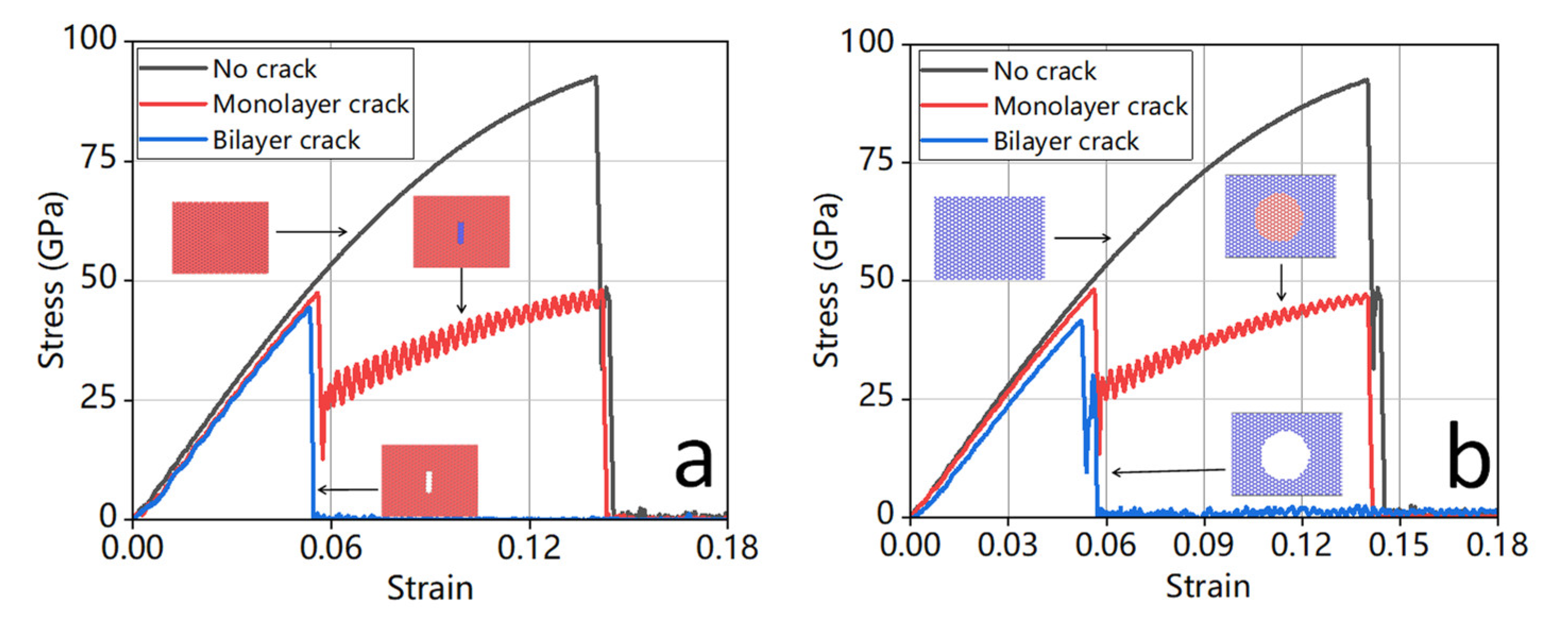
3.5. Comparison between Monolayer Cracks and Bilayer Cracks

Our analysis highlights the significant influence of crack shape and the number of crack layers on the mechanical properties of bilayer graphene, as depicted in Figure 11. The stress–strain curve of bilayer graphene experiences a steep drop when cracks are present. We find that different crack shapes result in similar impacts on the stress–strain response. Also, the presence of cracks leads to a decrease in stress–strain, regardless of monolayer cracks or bilayer cracks. Both monolayer cracks and bilayer cracks significantly affect the stress–strain of graphene, with the latter being more susceptible to fracture. Table 4 and Table 5 summarize the mechanical properties, emphasizing the effect of crack shape and the number of crack layers on the mechanical properties of bilayer graphene. In our study, the layer with pre-existing cracks experienced fracture at a strain of around 0.06, while the other layer without cracks remained intact, allowing for further loading until the second layer failed. The stress–strain curves exhibit a distinctive double peak signal, which suggests a subsequent fracture of the two layers due to the presence of cracks on a single layer. We might be able to detect the number of layers in graphene by counting the number of distinctive peaks in the stress–strain curve. We also find that, in the case of a monolayer crack, the layer without the crack stabilized the cracked layer to a small extent, as shown in Figure 11, the red line is on the right of the blue line during the first fracture. In addition, we might be able to detect the number of layers in graphene by counting the number of distinctive peaks in the stress–strain curve.

4. Conclusions

We used molecular dynamics simulations to investigate the impact of cracks and finite temperatures on the tensile properties of bilayer graphene. In particular, Young’s modulus, fracture strain, fracture stress, and fracture toughness were measured, and the effects of system size, pressure, and temperature on these properties were examined. The results revealed that the geometry and orientation of the cracks have a significant influence on the tensile properties of bilayer graphene. The stress–strain curves exhibit a distinctive double-peak signal, which suggests a subsequent fracture of the two layers due to the presence of cracks on a single layer. Furthermore, both hexagonal and circular cracks lead to a smaller Young’s modulus and toughness compared to rectangular cracks of the same size, and the orientation of the crack has a pronounced effect on the mechanical properties, with the crack along the x direction resulting in 2.5 times higher toughness than the crack along the y direction for the case of a length of 15 Å. Additionally, Young’s modulus decreases with increasing temperature in bilayer graphene with cracks on both layers.
The study’s findings provide valuable insights into potential applications of bilayer graphene in the design of advanced nanoscale electronic devices. It is essential to note, however, that the study was conducted on bilayer graphene in a free-standing state. In most graphene-based applications, a substrate is present, which may affect their mechanical properties. The extent of this effect is determined by the interaction between the substrate and graphene, which is typically weak and via Van der Waals forces. Hence, it is necessary to conduct a comprehensive investigation into the influence of the substrate on bilayer graphene to fully understand its behavior in practical applications. Overall, the study’s findings have practical implications for the design and fabrication of graphene-based devices and highlight the importance of considering the geometry and orientation of cracks in bilayer graphene.

Author Contributions

Conceptualization, Q.P. and H.-K.T.; methodology, T.Y., Z.Y. and H.L.; software, T.Y., Z.Y. and H.L.; validation, T.Y. and J.L.; formal analysis, T.Y., J.L. and H.-K.T.; investigation, H.-K.T.; resources, H.-K.T.; data curation, T.Y. and H.-K.T.; writing—original draft preparation, T.Y. and J.L.; writing—review and editing, T.Y., J.L., Q.P. and H.-K.T.; visualization, J.L. and H.-K.T.; supervision, H.L., Q.P. and H.-K.T.; project administration, H.-K.T.; funding acquisition, H.L., Q.P. and H.-K.T. All authors have read and agreed to the published version of the manuscript.

Funding

This research was funded by the Start-Up Research Fund in HITSZ (Grant No. ZX20210478, Grant No. X20220001) and the Young Scientists Fund of the National Natural Science Foundation of China (Grant No. 12204130). H.P.L. acknowledges the support of the Fundamental Research Funds for the Central Universities of China (Grant No. 2019ZDPY16) and Key Academic Discipline Project of CUMT (Grant No. 2022WLXK08). Q.P. would like to acknowledge the support provided by the Shenzhen Science and Technology Program (Grant No. KQTD20200820113045081), National Natural Science Foundation of China (Grant No. 12272378), and LiYing Program of the Institute of Mechanics, Chinese Academy of Sciences (Grant No. E1Z1011001).

Data Availability Statement

The data presented in this study are available on request.

Conflicts of Interest

The authors declare no conflict of interest. The funders had no role in the design of the study; in the collection, analyses, or interpretation of data; in the writing of the manuscript, or in the decision to publish the results.

References

  1. Novoselov, K.S.; Geim, A.K.; Morozov, S.V.; Jiang, D.; Zhang, Y.; Dubonos, S.V.; Grigorieva, I.V.; Firsov, A.A. Electric field effect in atomically thin carbon films. Science 2004, 306, 666–669. [Google Scholar] [CrossRef] [Green Version]
  2. Aliofkhazraei, M.; Ali, N.; Milne, W.I.; Ozkan, C.S.; Mitura, S.; Gervasoni, J.L. Mechanical properties of graphene. In Graphene Science Handbook; CRC Press: Boca Raton, FL, USA, 2016; pp. 19–32. [Google Scholar]
  3. Anastasi, A.A.; Ritos, K.; Cassar, G.; Borg, M.K. Mechanical properties of pristine and nanoporous graphene. Mol. Simul. 2016, 42, 1502–1511. [Google Scholar] [CrossRef] [Green Version]
  4. Dewapriya, M.A.N.; Phani, A.S.; Rajapakse, R.K.N.D. Influence of temperature and free edges on the mechanical properties of graphene. Model. Simul. Mater. Sci. Eng. 2013, 21, 065017. [Google Scholar] [CrossRef]
  5. Zandiatashbar, A.; Lee, G.-H.; An, S.J.; Lee, S.; Mathew, N.; Terrones, M.; Hayashi, T.; Picu, C.R.; Hone, J.; Koratkar, N. Effect of defects on the intrinsic strength and stiffness of graphene. Nat. Commun. 2014, 5, 3186. [Google Scholar] [CrossRef] [Green Version]
  6. Cheng, Y.; Zhou, S.; Hu, P.; Zhao, G.; Li, Y.; Zhang, X.; Han, W. Enhanced mechanical, thermal, and electric properties of graphene aerogels via supercritical ethanol drying and high-temperature thermal reduction. Sci. Rep. 2017, 7, 1439. [Google Scholar] [CrossRef] [PubMed] [Green Version]
  7. Ranjbartoreh, A.R.; Wang, B.; Shen, X.; Wang, G. Advanced mechanical properties of graphene paper. J. Appl. Phys. 2011, 109, 014306. [Google Scholar] [CrossRef]
  8. Li, X.; Guo, J. Numerical Investigation of the Fracture Properties of Pre-Cracked Monocrystalline/Polycrystalline Graphene Sheets. Materials 2019, 12, 263. [Google Scholar] [CrossRef] [PubMed] [Green Version]
  9. Akinwande, D.; Brennan, C.J.; Bunch, J.S.; Egberts, P.; Felts, J.R.; Gao, H.; Huang, R.; Kim, J.S.; Li, T.; Li, Y.; et al. A review on mechanics and mechanical properties of 2D materials—Graphene and beyond. Extrem. Mech. Lett. 2017, 13, 42–77. [Google Scholar] [CrossRef] [Green Version]
  10. Cao, Q.; Geng, X.; Wang, H.; Wang, P.; Liu, A.; Lan, Y.; Peng, Q. A Review of Current Development of Graphene Mechanics. Crystals 2018, 8, 357. [Google Scholar] [CrossRef] [Green Version]
  11. Lee, G.-H.; Cooper, R.C.; An, S.J.; Lee, S.; van der Zande, A.; Petrone, N.; Hammerberg, A.G.; Lee, C.; Crawford, B.; Oliver, W.; et al. High-strength chemical-vapor-deposited graphene and grain boundaries. Science 2013, 340, 1073–1076. [Google Scholar] [CrossRef] [PubMed]
  12. Neto, A.C.; Guinea, F.; Peres, N.M.; Novoselov, K.S.; Geim, A.K. The electronic properties of graphene. Rev. Mod. Phys. 2009, 81, 109–162. [Google Scholar] [CrossRef] [Green Version]
  13. Balandin, A.A.; Ghosh, S.; Bao, W.; Calizo, I.; Teweldebrhan, D.; Miao, F.; Lau, C.N. Superior thermal conductivity of single-layer graphene. Nano Lett. 2008, 8, 902–907. [Google Scholar] [CrossRef]
  14. Zhao, Q.; Nardelli, M.B.; Bernholc, J. Ultimate strength of carbon nanotubes: A theoretical study. Phys. Rev. B 2002, 65, 144105. [Google Scholar] [CrossRef] [Green Version]
  15. Allen, M.J.; Tung, V.C.; Kaner, R.B. Honeycomb carbon: A review of graphene. Chem. Rev. 2010, 110, 132–145. [Google Scholar] [CrossRef]
  16. McCann, E. Interlayer asymmetry gap in the electronic band structure of bilayer graphene. Phys. Status Solidi. B Basic Res. 2007, 244, 4112–4117. [Google Scholar] [CrossRef] [Green Version]
  17. McCann, E. Asymmetry gap in the electronic band structure of bilayer graphene. Phys. Review. B Condens. Matter 2006, 74, 161403. [Google Scholar] [CrossRef] [Green Version]
  18. Spirito, D.; Coquillat, D.; De Bonis, S.L.; Lombardo, A.; Bruna, M.; Ferrari, A.C.; Pellegrini, V.; Tredicucci, A.; Knap, W.; Vitiello, M.S. High performance bilayer-graphene terahertz detectors. Appl. Phys. Lett. 2014, 104, 061111. [Google Scholar] [CrossRef] [Green Version]
  19. Fiori, G.; Neumaier, D.; Szafranek, B.N.; Iannaccone, G. Bilayer Graphene Transistors for Analog Electronics. IEEE Trans. Electron Devices 2014, 61, 729–733. [Google Scholar] [CrossRef]
  20. Xia, F.; Farmer, D.B.; Lin, Y.-M.; Avouris, P. Graphene field-effect transistors with high on/off current ratio and large transport band gap at room temperature. Nano Lett. 2010, 10, 715–718. [Google Scholar] [CrossRef] [Green Version]
  21. Zeng, L.; Xie, C.; Tao, L.; Long, H.; Tang, C.; Tsang, Y.H.; Jie, J. Bilayer graphene based surface passivation enhanced nano structured self-powered near-infrared photodetector. Opt. Express 2015, 23, 4839–4846. [Google Scholar] [CrossRef] [PubMed]
  22. Yan, H. Bilayer graphene: Physics and application outlook in photonics. Nanophotonics 2015, 4, 115–127. [Google Scholar] [CrossRef]
  23. Zhang, Y.Y.; Gu, Y.T. Mechanical properties of graphene: Effects of layer number, temperature and isotope. Comput. Mater. Sci. 2013, 71, 197–200. [Google Scholar] [CrossRef] [Green Version]
  24. Afyouni Akbari, S.; Ghafarinia, V.; Larsen, T.; Parmar, M.M.; Villanueva, L.G. Large Suspended Monolayer and Bilayer Graphene Membranes with Diameter up to 750 µm. Sci. Rep. 2020, 10, 6426. [Google Scholar] [CrossRef] [Green Version]
  25. Chen, M.-C.; Hsu, C.-L.; Hsueh, T.-J. Fabrication of Humidity Sensor Based on Bilayer Graphene. IEEE Electron Device Lett. 2014, 35, 590–592. [Google Scholar] [CrossRef]
  26. Nimbalkar, A.; Kim, H. Opportunities and Challenges in Twisted Bilayer Graphene: A Review. Nano-Micro Lett. 2020, 12, 126. [Google Scholar] [CrossRef] [PubMed]
  27. Saharudin, M.S.; Hasbi, S.; Rashidi, N.M.; Nordin, M.S.J. Effect of short-term water exposure on mechanical properties of multi-layer graphene and multi-walled carbon nanotubes-reinforced epoxy nanocomposites. J. Eng. Sci. Technol. 2018, 13, 4226–4239. [Google Scholar]
  28. Alahmed, I.I.; Altanany, S.M.; Abdulazeez, I.; Shoaib, H.; Alsayoud, A.Q.; Abbout, A.; Peng, Q. The Crack Angle of 60° Is the Most Vulnerable Crack Front in Graphene According to MD Simulations. Crystals 2021, 11, 1355. [Google Scholar] [CrossRef]
  29. Wavrunek, T.; Peng, Q.; Abu-Zahra, N. Mechanical Properties and Buckling of Kagome Graphene under Tension: A Molecular Dynamics Study. Crystals 2022, 12, 292. [Google Scholar] [CrossRef]
  30. Li, H.; Zhang, H.; Cheng, X. The effect of temperature, defect and strain rate on the mechanical property of multi-layer graphene: Coarse-grained molecular dynamics study. Phys. E Low-Dimens. Syst. Nanostruct. 2017, 85, 97–102. [Google Scholar] [CrossRef]
  31. Kordkheili, S.H.; Moshrefzadeh-Sani, H. Mechanical properties of double-layered graphene sheets. Comput. Mater. Sci. 2013, 69, 335–343. [Google Scholar] [CrossRef]
  32. Chu, L.; Shi, J.; Braun, R. The equivalent Young’s modulus prediction for vacancy defected graphene under shear stress. Phys. E Low-Dimens. Syst. Nanostruct. 2019, 110, 115–122. [Google Scholar] [CrossRef]
  33. Zhang, Y.; Pan, C. Measurements of mechanical properties and number of layers of graphene from nano-indentation. Diam. Relat. Mater. 2012, 24, 1–5. [Google Scholar] [CrossRef]
  34. Liu, A.; Peng, Q. A Molecular Dynamics Study of the Mechanical Properties of Twisted Bilayer Graphene. Micromachines 2018, 9, 440. [Google Scholar] [CrossRef] [Green Version]
  35. Guadagno, L.; Raimondo, M.; Vertuccio, L.; Mauro, M.; Guerra, G.; Lafdi, K.; De Vivo, B.; Lamberti, P.; Spinelli, G.; Tucci, V. Optimization of graphene-based materials outperforming host epoxy matrices. RSC Adv. 2015, 5, 36969–36978. [Google Scholar] [CrossRef] [Green Version]
  36. Jin, X.; Adpakpang, K.; Kim, I.Y.; Oh, S.M.; Lee, N.-S.; Hwang, S.-J. An Effective Way to Optimize the Functionality of Graphene-Based Nanocomposite: Use of the Colloidal Mixture of Graphene and Inorganic Nanosheets. Sci. Rep. 2015, 5, 11057. [Google Scholar] [CrossRef] [PubMed] [Green Version]
  37. Duong, H.M.; Tran, T.Q.; Kopp, R.; Myint, S.M.; Peng, L. Chapter 1—Direct Spinning of Horizontally Aligned Carbon Nanotube Fibers and Films From the Floating Catalyst Method, 2nd ed.; Schulz, M.J., Shanov, V., Yin, Z., Cahay, M., Eds.; Nanotube Superfiber Materials; William Andrew Publishing: Norwich, NY, USA, 2019; pp. 3–29. [Google Scholar]
  38. Duong, H.M.; Myint, S.M.; Tran, T.Q.; Le, D.K. Post-spinning treatments to carbon nanotube fibers. In Carbon Nanotube Fibers and Yarns; Elsevier: Amsterdam, The Netherlands, 2020; pp. 103–134. [Google Scholar]
  39. Plimpton, S. Fast parallel algorithms for short-range molecular dynamics. J. Comput. Phys. 1995, 117, 1–19. [Google Scholar] [CrossRef] [Green Version]
  40. Stukowski, A. Visualization and analysis of atomistic simulation data with OVITO–the Open Visualization Tool. Model. Simul. Mater. Sci. Eng. 2010, 18, 015012. [Google Scholar] [CrossRef]
  41. Humphrey, W.; Dalke, A.; Schulten, K. VMD: Visual molecular dynamics. J. Mol. Graph. 1996, 14, 33–38. [Google Scholar] [CrossRef]
  42. Stuart, S.J.; Tutein, A.B.; Harrison, J.A. A reactive potential for hydrocarbons with intermolecular interactions. J. Chem. Phys. 2000, 112, 6472–6486. [Google Scholar] [CrossRef] [Green Version]
  43. Yang, X.; Wu, S.; Xu, J.; Cao, B.; To, A.C. Spurious heat conduction behavior of finite-size graphene nanoribbon under extreme uniaxial strain caused by the AIREBO potential. Phys. E Low-Dimens. Syst. Nanostruct. 2018, 96, 46–53. [Google Scholar] [CrossRef]
  44. Wang, X.; Hong, Y.; Ma, D.; Zhang, J. Molecular dynamics study of thermal transport in a nitrogenated holey graphene bilayer. J. Mater. Chem. 2017, 5, 5119–5127. [Google Scholar] [CrossRef]
  45. Zhang, P.; Ma, L.; Fan, F.; Zeng, Z.; Peng, C.; Loya, P.E.; Liu, Z.; Gong, Y.; Zhang, J.; Zhang, X.; et al. Fracture toughness of graphene. Nat. Commun. 2014, 5, 3782. [Google Scholar] [CrossRef] [PubMed] [Green Version]
  46. Guo, Y.; Zhou, M.; Sun, X.; Qian, L.; Li, L.; Xie, Y.; Liu, Z.; Wu, D.; Yang, L.; Wu, T.; et al. Effects of Temperature and Strain Rate on the Fracture Behaviors of an Al-Zn-Mg-Cu Alloy. Materials 2018, 11, 1233. [Google Scholar] [CrossRef] [PubMed] [Green Version]
Figure 1. (a) Bilayer graphene with interlayer spacing 3.4 Å; (b) the shape of cracks on the graphene surface, including rectangular cracks, circular cracks, and Hexagonal cracks.
Crystals 13 00584 g001
Figure 2. The effect of increasing the number of atoms on the mechanical properties of bilayer graphene. (a) Stress–strain relationships, (b) Fracture stress and Fracture strain, (c) Young’s modulus, (d) Toughness. As the variation in the number of atoms has a limited impact on the mechanical properties of bilayer graphene, we selected 11,928 atoms in this study.
Crystals 13 00584 g002
Figure 3. Mechanical properties of bilayer graphene with increasing temperature. (a) Stress–strain relationships, (b) fracture strain and fracture stress, (c) Young’s modulus, and (d) fracture toughness. Both the linear elastic part and the nonlinear part of the mechanics properties decayed with increasing temperature.
Crystals 13 00584 g003
Figure 4. Analysis of mechanical properties of bilayer graphene with rectangular cracks of different widths. (a,b) show stress–strain relationships for cracks oriented along the y- and x-axes, respectively. (ce) present fracture strain, fracture stress, Young’s modulus, and toughness of the samples with cracks along the x-axis, and (fh) along the y-axis. The results demonstrate the crack orientation has a great impact on the mechanical property of the bilayer graphene.
Crystals 13 00584 g004
Figure 5. The stress–strain curve of bilayer graphene with different orientations of the rectangular cracks (l = 10 Å).
Crystals 13 00584 g005
Figure 6. Mechanical properties analysis of bilayer-crack graphene with circular cracks of different diameters D (a) Stress–strain relationships (b) Fracture strain, (c) Fracture stress, (d) Young’s modulus. Both Young’s modulus and fracture toughness decayed with the increasing size of the circular crack.
Crystals 13 00584 g006
Figure 7. Mechanical properties analysis of bilayer-crack graphene with quasi-hexagonal cracks of different maximum vertex distance a of quasi-hexagon (a) Stress–strain relationships (b) Fracture strain, (c) Fracture stress, (d) Young’s modulus. Both Young’s modulus and fracture toughness decayed with the increasing size of the circular crack.
Crystals 13 00584 g007
Figure 8. Comparison of stress–strain curves between circular cracks and regular quasi-hexagonal cracks.
Crystals 13 00584 g008
Figure 9. Rectangular cracks of varying length on a single layer: (a) stress–strain relationships, (b) fracture strain, (c) fracture stress, and (d) Young’s modulus. The double peaks are observed in the stress–strain curves, indicating a subsequent fracture of the cracked layer and the uncracked layer.
Crystals 13 00584 g009
Figure 10. Mechanical properties of bilayer graphene with circular cracks of varying radii on a single layer: (a) stress–strain relationships, (b) fracture strain, (c) fracture stress, and (d) Young’s modulus. The stress–strain curves exhibit a distinctive double peak signal, which suggests a subsequent fracture of the two layers due to the presence of cracks on a single layer.
Crystals 13 00584 g010
Figure 11. Comparison of stress–strain curves of the bilayer graphene with (black) no crack, (red) the crack on a single layer, and (blue) the cracks on both layers for (a) the rectangular crack along the y-axis, and (b) the circular crack.
Crystals 13 00584 g011
Table 1. Rectangular cracks with different orientations (l = 10 Å).
Crack OrientationFracture StrainFracture Stress (GPa)Young’s Modulus (GPa)Toughness
(J m−3)
Along x-axis0.0867.93917.163.11
Along y-axis0.0649.41874.661.19
Table 2. Circular crack.
D (Å)Fracture StrainFracture Stress (GPa)Young’s Modulus (GPa)Toughness
(J m−3)
12.300.0651.63911.771.84
17.220.0644.76875.811.27
22.140.0540.68841.451.06
Table 3. Quasi-hexagonal crack.
a (Å)Fracture StrainFracture Stress (GPa)Young’s Modulus (GPa)Toughness
(J m−3)
12.300.0654.95921.141.89
17.220.0649.17905.491.48
22.140.0543.68876.541.17
Table 4. Rectangular crack along the y-axis (l = 10 Å).
CrackFracture StrainFracture Stress (GPa)Young’s Modulus (GPa)Toughness
(J m−3)
No crack0.1492.57930.597.96
Monolayer crack0.0547.46889.594.60
Bilayer crack0.0544.43872.031.19
Table 5. Circular crack (D = 10 Å).
CrackFracture StrainFracture Stress (GPa)Young’s Modulus (GPa)Toughness
(J m−3)
No crack0.1492.57930.597.96
Monolayer crack0.0653.90913.224.66
Bilayer crack0.0654.94899.001.85
Disclaimer/Publisher’s Note: The statements, opinions and data contained in all publications are solely those of the individual author(s) and contributor(s) and not of MDPI and/or the editor(s). MDPI and/or the editor(s) disclaim responsibility for any injury to people or property resulting from any ideas, methods, instructions or products referred to in the content.

