


Hydroxyapatite-Barium Titanate Biocoatings Using Room Temperature Coblasting

 ,
,  ,
,  and
and 
Abstract
:1. Introduction
2. Materials and Methods
2.1. Materials
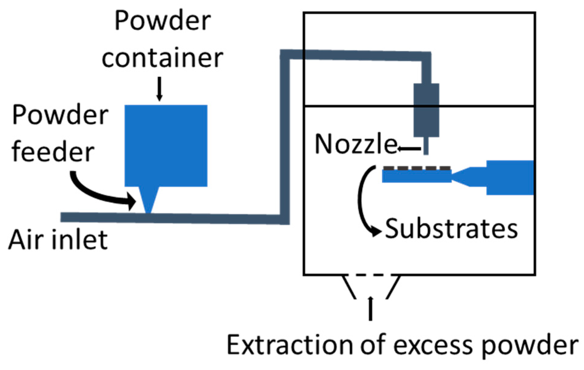
2.2. CB and PS
2.3. Characterisation
3. Results
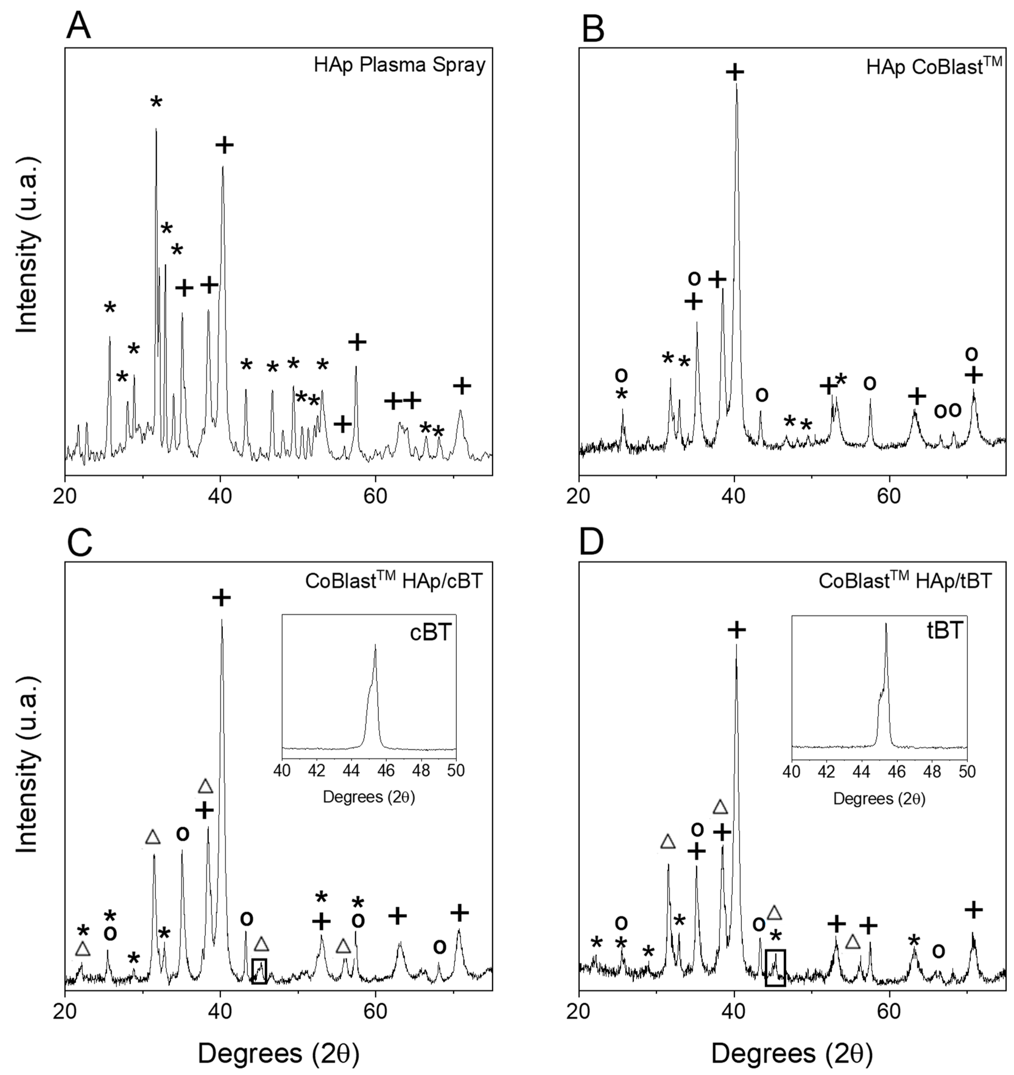
3.1. XRD
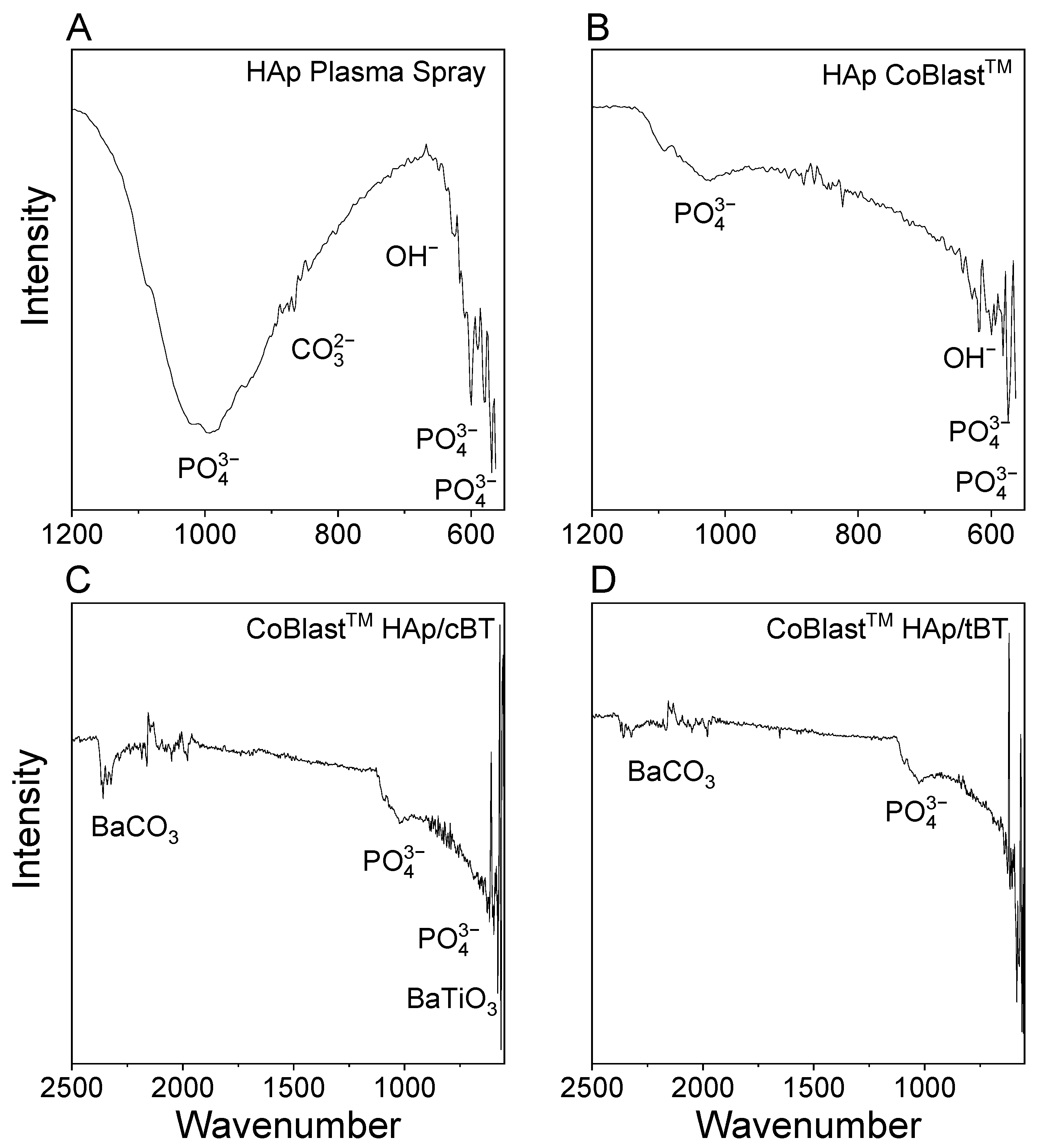
3.2. FTIR
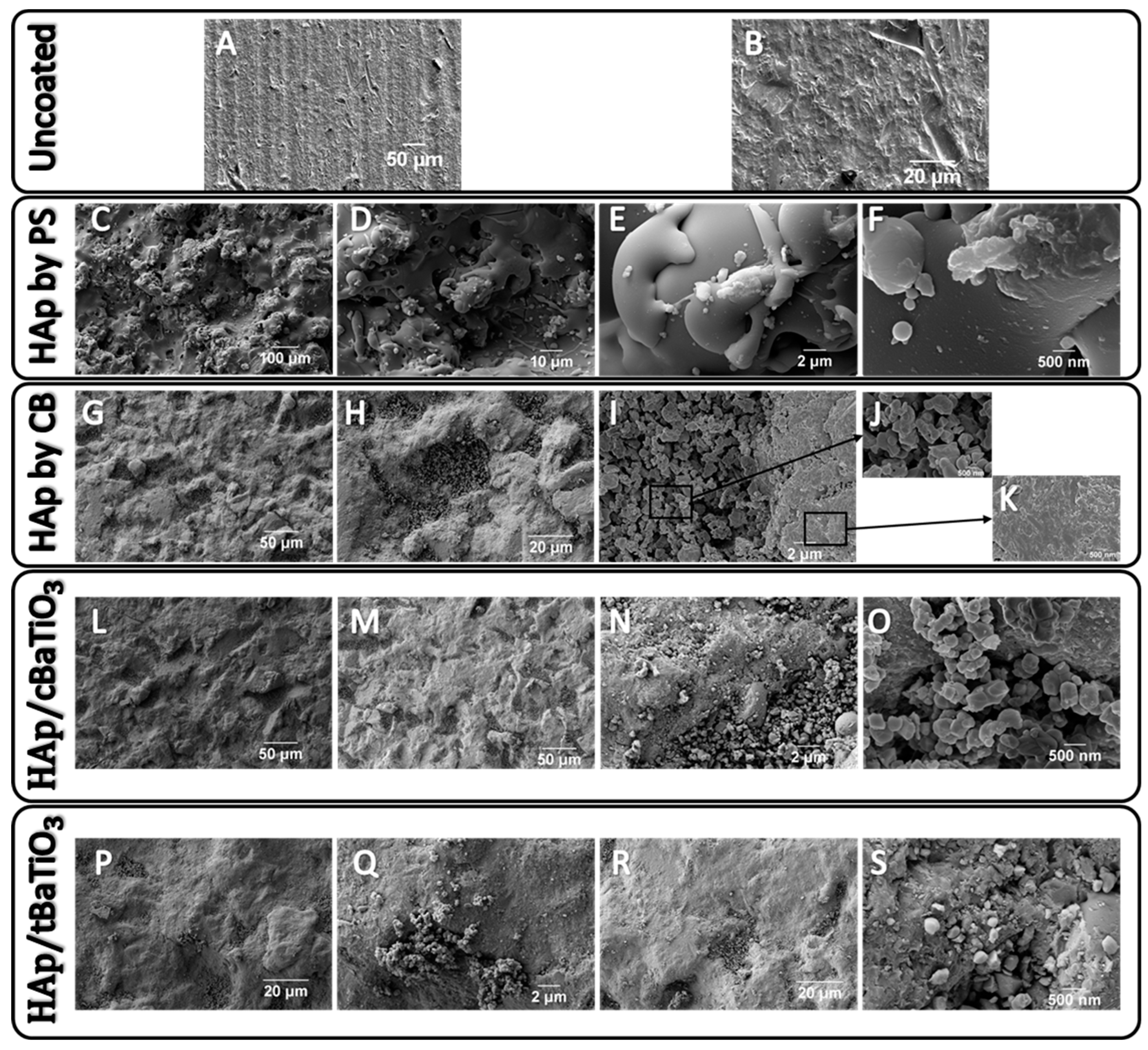
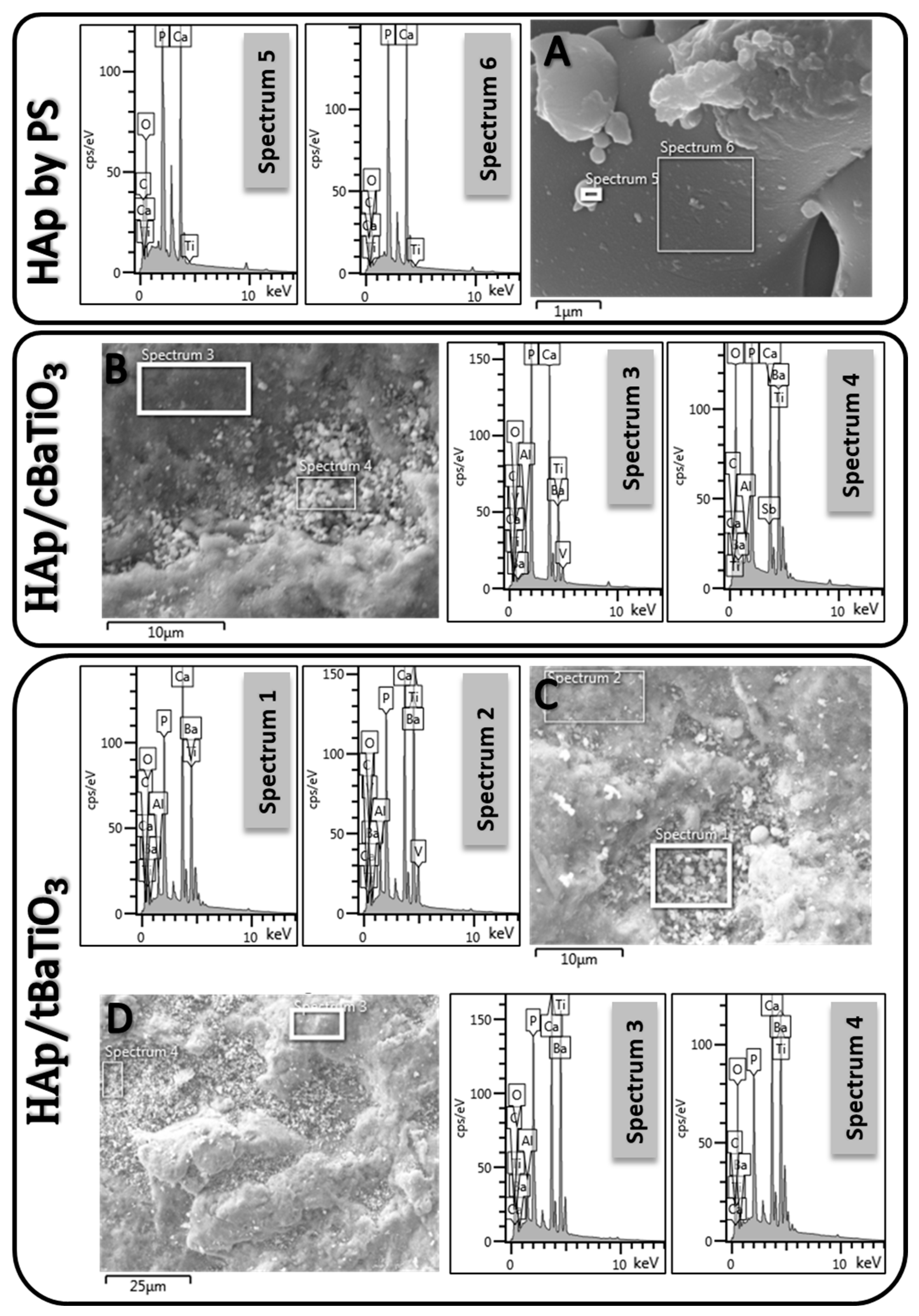
3.3. SEM-EDS
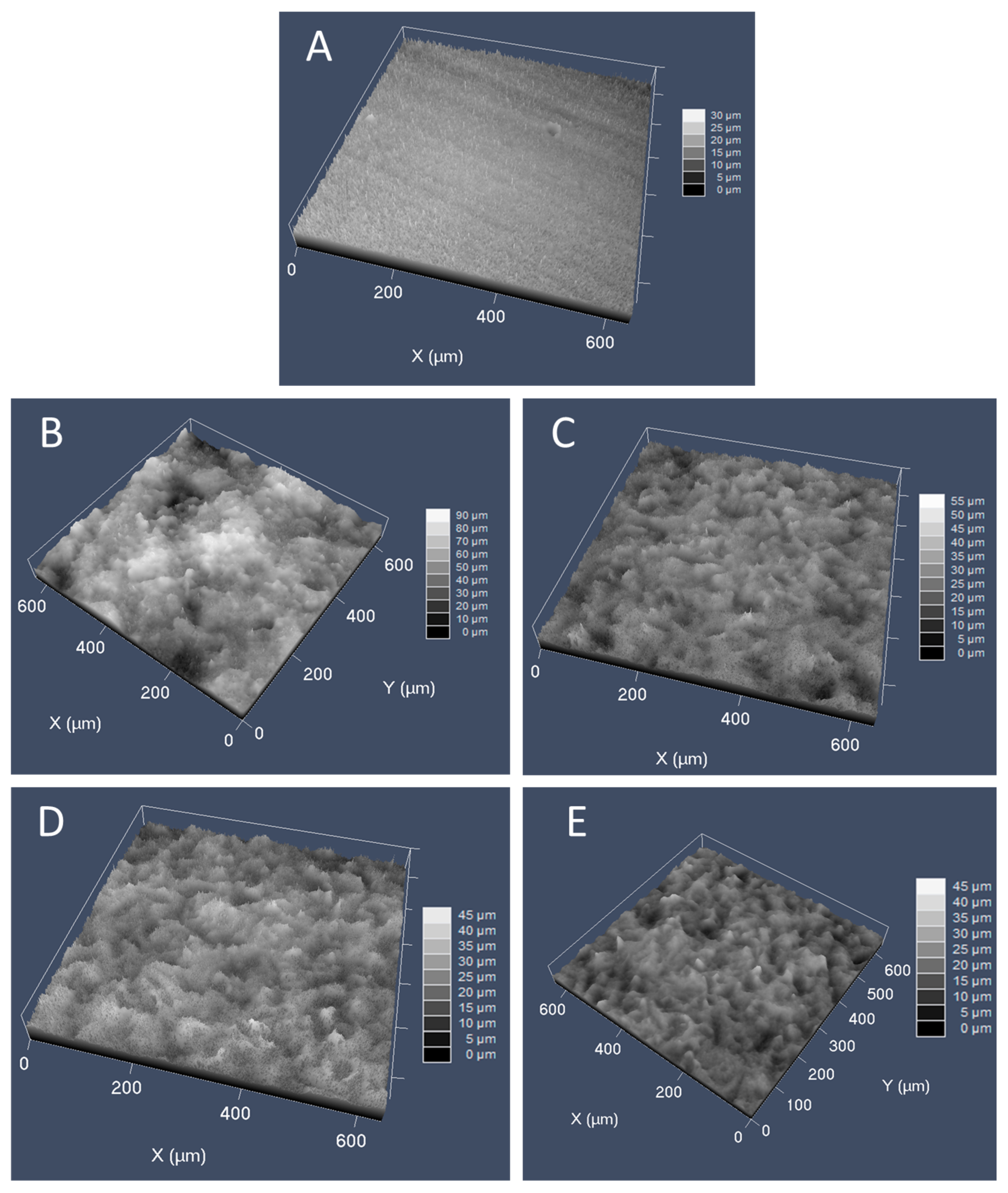
3.4. Confocal Microscopy
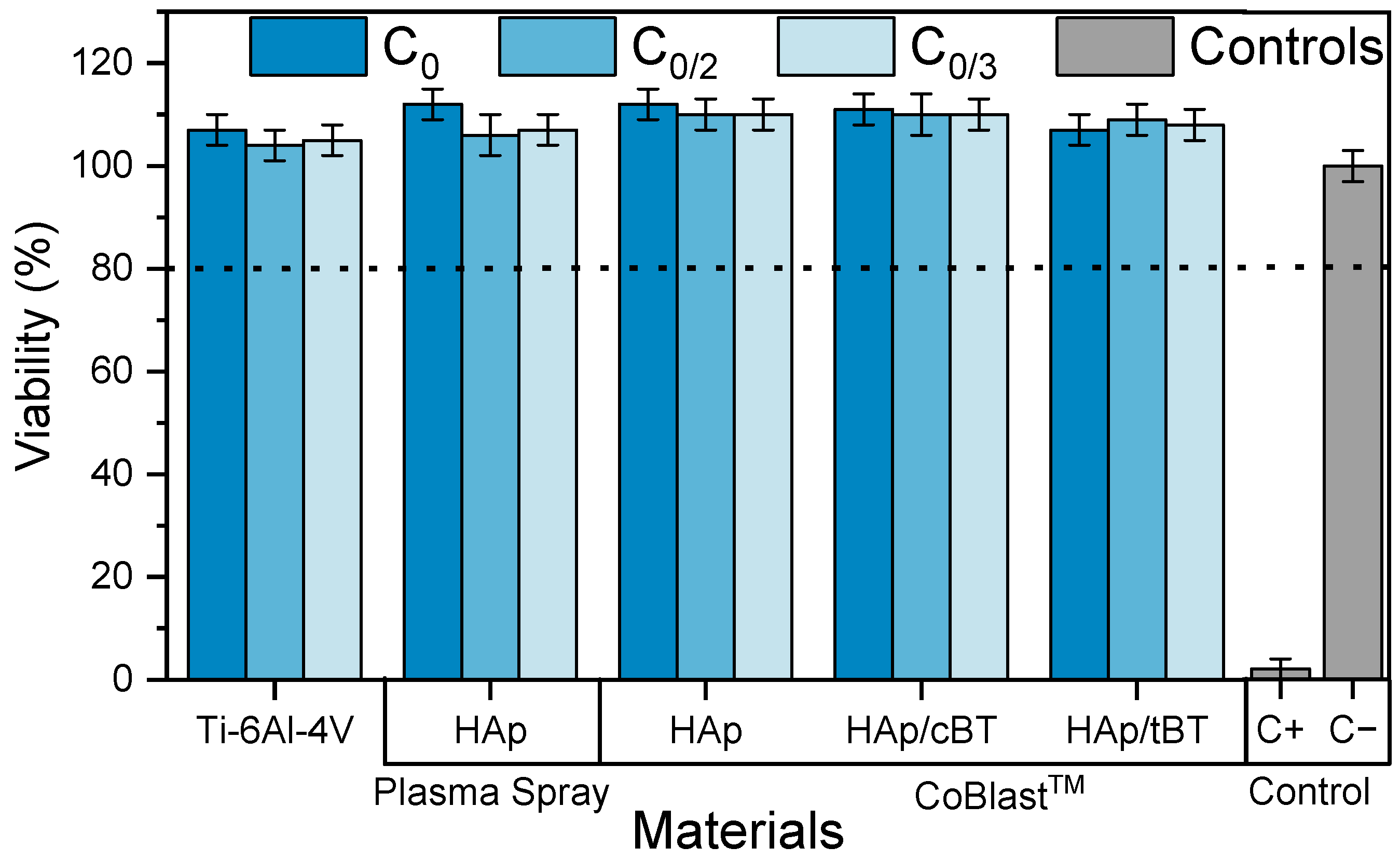
3.5. Cytotoxicity
4. Conclusions
Author Contributions
Funding
Data Availability Statement
Acknowledgments
Conflicts of Interest
References
- Barrère, F.; Mahmood, T.A.; de Groot, K.; van Blitterswijk, C.A. Advanced Biomaterials for Skeletal Tissue Regeneration: Instructive and Smart Functions. Mater. Sci. Eng. R Rep. 2008, 59, 38–71. [Google Scholar] [CrossRef]
- Bosco, R.; Van Den Beucken, J.V.; Leeuwenburgh, S.; Jansen, J. Surface Engineering for Bone Implants: A Trend from Passive to Active Surfaces. Coatings 2012, 2, 95–119. [Google Scholar] [CrossRef] [Green Version]
- LaWell, C. Orthopedic Market Projected to Grow 3.4% in 2022. Available online: https://www.orthoworld.com/orthopedic-market-projected-to-grow-3-4-in-2022/ (accessed on 18 January 2023).
- The Orthopedic Implants Market to Be Valued at $74.90 Billion by 2030; Expected to Witness a CAGR of 5.53%: Quintile Insigths-Healthcare. Available online: https://www.linkedin.com/pulse/orthopedic-implants-market-valued-7490-billion-2030-expected-/ (accessed on 19 January 2023).
- Scholz, M.S.; Blanchfield, J.P.; Bloom, L.D.; Coburn, B.H.; Elkington, M.; Fuller, J.D.; Gilbert, M.E.; Muflahi, S.A.; Pernice, M.F.; Rae, S.I.; et al. The Use of Composite Materials in Modern Orthopaedic Medicine and Prosthetic Devices: A Review. Compos. Sci. Technol. 2011, 71, 1791–1803. [Google Scholar] [CrossRef]
- Shen, P.; Chen, Y.; Luo, S.; Fan, Z.; Wang, J.; Chang, J.; Deng, J. Applications of Biomaterials for Immunosuppression in Tissue Repair and Regeneration. Acta Biomater. 2021, 126, 31–44. [Google Scholar] [CrossRef]
- Fröhlich, L. MicroRNAs at the Interface between Osteogenesis and Angiogenesis as Targets for Bone Regeneration. Cells 2019, 8, 121. [Google Scholar] [CrossRef] [Green Version]
- Jones, J.R. Scaffolds for Tissue Engineering. In Biomaterials, Artificial Organs and Tissue Engineering; Hench, L.L., Jones, J.R., Eds.; Woodhead Publishing: Swaston, UK, 2005; pp. 201–214. ISBN 9781855737372. [Google Scholar]
- Hench, L.L. Biomaterials: A Forecast for the Future. Biomaterials 1998, 151, 1419–1423. [Google Scholar] [CrossRef]
- Kato, E.; Yamada, M.; Sakurai, K. Retrospective Clinical Outcome of Nanopolymorphic Crystalline Hydroxyapatite-Coated and Anodic Oxidized Titanium Implants for 10 Years. J. Prosthodont. Res. 2015, 59, 62–70. [Google Scholar] [CrossRef]
- Tavangar, M.; Heidari, F.; Hayati, R.; Tabatabaei, F.; Vashaee, D.; Tayebi, L. Manufacturing and Characterization of Mechanical, Biological and Dielectric Properties of Hydroxyapatite-Barium Titanate Nanocomposite Scaffolds. Ceram. Int. 2020, 46, 9086–9095. [Google Scholar] [CrossRef]
- Ielo, I.; Calabrese, G.; De Luca, G.; Conoci, S. Recent Advances in Hydroxyapatite-Based Biocomposites for Bone Tissue Regeneration in Orthopedics. Int. J. Mol. Sci. 2022, 23, 9721. [Google Scholar] [CrossRef]
- Turner, C.H.; Burr, D.B. Basic Biomechanical Measurements of Bone: A Tutorial. Bone 1993, 14, 595–608. [Google Scholar] [CrossRef]
- De Long, W.G.; Einhorn, T.A.; Koval, K.; McKee, M.; Smith, W.; Sanders, R.; Watson, T. Bone Grafts and Bone Graft Substitutes in Orthopaedic Trauma Surgery. A Critical Analysis. J. Bone Jt. Surg. Am. 2007, 89, 649–658. [Google Scholar] [CrossRef]
- Santos, M.; Santos, C.; Carmezim, M.J. Production of Bioactive Hydroxyapatite Coating by Coblast Process for Orthopedic Implants. In Proceedings of the 2019 IEEE 6th Portuguese Meeting on Bioengineering (ENBENG), Lisbon, Portugal, 22–23 February 2019; pp. 1–4. [Google Scholar]
- Prezas, P.R.; Dekhtyar, Y.; Sorokins, H.; Costa, M.M.; Soares, M.J.; Graça, M.P.F. Electrical Charging of Bioceramics by Corona Discharge. J. Electrostat. 2022, 115, 103664. [Google Scholar] [CrossRef]
- Liu, D.M.; Chou, H.M.; Wu, J.D. Plasma-Sprayed Hydroxyapatite Coating: Effect of Different Calcium Phosphate Ceramics. J. Mater. Sci. Mater. Med. 1994, 5, 147–153. [Google Scholar] [CrossRef]
- Landor, I.; Vavrik, P.; Sosna, A.; Jahoda, D.; Hahn, H.; Daniel, M. Hydroxyapatite Porous Coating and the Osteointegration of the Total Hip Replacement. Arch. Orthop. Trauma Surg. 2007, 127, 81–89. [Google Scholar] [CrossRef]
- Sun, L.; Berndt, C.C.; Gross, K.A.; Kucuk, A. Material Fundamentals and Clinical Performance of Plasma-Sprayed Hydroxyapatite Coatings: A Review. J. Biomed. Mater. Res. 2001, 58, 570–592. [Google Scholar] [CrossRef] [PubMed]
- Sun, L.; Berndt, C.C.; Grey, C.P. Phase, Structural and Microstructural Investigations of Plasma Sprayed Hydroxyapatite Coatings. Mater. Sci. Eng. A 2003, 360, 70–84. [Google Scholar] [CrossRef]
- Xue, W.; Tao, S.; Liu, X.; Zheng, X.; Ding, C. In Vivo Evaluation of Plasma Sprayed Hydroxyapatite Coatings Having Different Crystallinity. Biomaterials 2004, 25, 415–421. [Google Scholar] [CrossRef]
- Inadome, T.; Hayashi, K.; Nakashima, Y.; Tsumura, H.; Sugioka, Y. Comparison of Bone-implant Interface Shear Strength of Hydroxyapatite-coated and Alumina-coated Metal Implants. J. Biomed. Mater. Res. 1995, 29, 19–24. [Google Scholar] [CrossRef]
- Dunne, C.F.; Roche, K.; Janssen, A.; Zhong, X.; Burke, M.G.; Twomey, B.; Stanton, K.T. Ultrafine Grain Formation and Coating Mechanism Arising from a Blast Coating Process: A Transmission Electron Microscopy Analysis. Surf. Interface Anal. 2017, 49, 1271–1278. [Google Scholar] [CrossRef] [Green Version]
- O’Neill, L.; O’Sullivan, C.; O’Hare, P.; Sexton, L.; Keady, F.; O’Donoghue, J. Deposition of Substituted Apatites onto Titanium Surfaces Using a Novel Blasting Process. Surf. Coat. Technol. 2009, 204, 484–488. [Google Scholar] [CrossRef]
- Barry, J.N.; Dowling, D.P. Comparison between the SBF Response of Hydroxyapatite Coatings Deposited Using Both a Plasma-Spray and a Novel Co-Incident Micro-Blasting Technique. Key Eng. Mater. 2011, 493–494, 483–488. [Google Scholar] [CrossRef]
- Tan, F.; Naciri, M.; Dowling, D.; Al-Rubeai, M. In Vitro and in Vivo Bioactivity of CoBlast Hydroxyapatite Coating and the Effect of Impaction on Its Osteoconductivity. Biotechnol. Adv. 2012, 30, 352–362. [Google Scholar] [CrossRef] [PubMed]
- Khare, D.; Basu, B.; Dubey, A.K. Electrical Stimulation and Piezoelectric Biomaterials for Bone Tissue Engineering Applications. Biomaterials 2020, 258, 120280. [Google Scholar] [CrossRef] [PubMed]
- Wolff, J. The Law of Bone Remodelling, 1st ed.; Springer: Berlin/Heidelberg, Germany, 1986; Volume 53, ISBN 978-3-642-71031-5. [Google Scholar]
- Fukada, E.; Yasuda, I. On the Piezoelectric Effect of Bone. J. Phys. Soc. Jpn. 1957, 12, 1158–1162. [Google Scholar] [CrossRef]
- Bodhak, S.; Bose, S.; Bandyopadhyay, A. Surface Modification and Electro-Thermal Polarisation for Bone Tissue Engineering. In Electrically Active Materials for Medical Devices; Imperial College Press: London, UK, 2016; pp. 103–114. [Google Scholar]
- Gómez Batres, R.; Guzmán Escobedo, Z.S.; Carrera Gutiérrez, K.; Leal Berumen, I.; Macias, A.H.; Herrera Pérez, G.; Orozco Carmona, V.M.; Escobedo, G.; Gutiérrez, Z.S.; Leal Berumen, K.C.; et al. Impact Evaluation of High Energy Ball Milling Homogenization Process in the Phase Distribution of Hydroxyapatite-Barium Titanate Plasma Spray Biocoating. Coatings 2021, 11, 728. [Google Scholar] [CrossRef]
- Senthilkumar, G.; Kaliaraj, G.S.; Vignesh, P.; Vishwak, R.S.; Joy, T.N.; Hemanandh, J. Hydroxyapatite—Barium/Strontium Titanate Composite Coatings for Better Mechanical, Corrosion and Biological Performance. Mater. Today Proc. 2021, 44, 3618–3621. [Google Scholar] [CrossRef]
- Flanagan, J.; Schütze, P.; Dunne, C.; Twomey, B.; Stanton, K.T. Use of a Blast Coating Process to Promote Adhesion between Aluminium Surfaces for the Automotive Industry. J. Adhes. 2020, 96, 580–601. [Google Scholar] [CrossRef]
- Young, R.A.; Brown, W.E. Structures of Biological Minerals. In Biological Mineralization and Demineralization: Report of the Dahlem Workshop on Biological Mineralization and Demineralization Berlin 1981, October 18–23; Springer: Berlin/Heidelberg, Germany, 1982; pp. 101–141. [Google Scholar] [CrossRef]
- de Souza, C.M.P.; Militão, V.A.; Silva, I.G.; de Oliveira, R.R.; Seriacopi, V.; Junior, W.C.d.S. Characterization of Ti-6Al-4V Titanium Alloy Applied in Hydroxyapatite Coated Hip Prostheses. Res. Soc. Dev. 2022, 11, e2211830629. [Google Scholar] [CrossRef]
- Elmer, J.W.; Palmer, T.A.; Wong, J. In Situ Observations of Phase Transitions in Ti-6Al-4V Alloy Welds Using Spatially Resolved X-ray Diffraction. J. Appl. Phys. 2018, 93, 1941. [Google Scholar] [CrossRef]
- Selamat, M.S.; Watson, L.M.; Baker, T.N. XRD and XPS Studies on Surface MMC Layer of SiC Reinforced Ti-6Al-4V Alloy. J. Mater. Process. Technol. 2003, 142, 725–737. [Google Scholar] [CrossRef]
- Kaschel, F.R.; Vijayaraghavan, R.K.; Shmeliov, A.; McCarthy, E.K.; Canavan, M.; McNally, P.J.; Dowling, D.P.; Nicolosi, V.; Celikin, M. Mechanism of Stress Relaxation and Phase Transformation in Additively Manufactured Ti-6Al-4V via in Situ High Temperature XRD and TEM Analyses. Acta Mater. 2020, 188, 720–732. [Google Scholar] [CrossRef]
- Ramires, I.; Guastaldi, A.C. Study of Ti-6A1-4V Biomaterial Using Electrochemistry and XPS Techniques. Quim. Nova 2002, 25, 10–14. [Google Scholar] [CrossRef]
- Barry, J.N.; Twomey, B.; Cowley, A.; O’Neill, L.; McNally, P.J.; Dowling, D.P. Evaluation and Comparison of Hydroxyapatite Coatings Deposited Using Both Thermal and Non-Thermal Techniques. Surf. Coat. Technol. 2013, 226, 82–91. [Google Scholar] [CrossRef]
- Abron, A.; Hopfensperger, M.; Thompson, J.; Cooper, L.F. Evaluation of a Predictive Model for Implant Surface Topography Effects on Early Osseointegration in the Rat Tibia Model. J. Prosthet. Dent. 2001, 85, 40–46. [Google Scholar] [CrossRef] [PubMed]
- Ossa, C.P.O.; Rogero, S.O.; Tschiptschin, A.P. Cytotoxicity Study of Plasma-Sprayed Hydroxyapatite Coating on High Nitrogen Austenitic Stainless Steels. J. Mater. Sci. Mater. Med. 2006, 17, 1095–1100. [Google Scholar] [CrossRef] [PubMed]
- Shamray, V.F.; Sirotinkin, V.P.; Kalita, V.I.; Komlev, V.S.; Barinov, S.M.; Fedotov, A.Y.; Gordeev, A.S. Study of the Crystal Structure of Hydroxyapatite in Plasma Coating. Surf. Coat. Technol. 2019, 372, 201–208. [Google Scholar] [CrossRef]
- Langford, J.I.; Wilson, A.J.C. IUCr Scherrer after Sixty Years: A Survey and Some New Results in the Determination of Crystallite Size. J. Appl. Crystallogr. 1978, 11, 102–113. [Google Scholar] [CrossRef]
- Monshi, A.; Foroughi, M.R.; Monshi, M.R.; Monshi, A.; Foroughi, M.R.; Monshi, M.R. Modified Scherrer Equation to Estimate More Accurately Nano-Crystallite Size Using XRD. World J. Nano Sci. Eng. 2012, 2, 154–160. [Google Scholar] [CrossRef] [Green Version]
- Demnati, I.; Grossin, D.; Marsan, O.; Bertrand, G.; Collonges, G.; Combes, C.; Parco, M.; Braceras, I.; Alexis, J.; Balcaen, Y. Comparison of Physical-Chemical and Mechanical Properties of Chlorapatite and Hydroxyapatite Plasma Sprayed Coatings. Open Biomed. Eng. J. 2014, 9, 26–39. [Google Scholar] [CrossRef] [Green Version]
- Thein-Han, W.W.; Misra, R.D.K. Biomimetic Chitosan–Nanohydroxyapatite Composite Scaffolds for Bone Tissue Engineering. Acta Biomater. 2008, 95, 147–155. [Google Scholar] [CrossRef]
- João, C.; Almeida, R.; Silva, J.; Borges, J. A Simple Sol-Gel Route to the Construction of Hydroxyapatite Inverted Colloidal Crystals for Bone Tissue Engineering. Mater. Lett. 2016, 185, 407–410. [Google Scholar] [CrossRef] [Green Version]
- Franco, P.Q.; João, C.F.C.; Silva, J.C.; Borges, J.P. Electrospun Hydroxyapatite Fibers from a Simple Sol–Gel System. Mater. Lett. 2012, 67, 233–236. [Google Scholar] [CrossRef]
- O’Sullivan, C.; O’Hare, P.; Byrne, G.; O’Neill, L.; Ryan, K.B.; Crean, A.M. A Modified Surface on Titanium Deposited by a Blasting Process. Coatings 2011, 1, 53–71. [Google Scholar] [CrossRef] [Green Version]
- Mohamed, E.A.; Nabhan, E.; Ratep, A.; Hassan, F.M.; Tahoon, K. Influence of BaTiO3 Nanoparticles/Clusters on the Structural and Dielectric Properties of Glasses-Nanocomposites. Phys. B Condens. Matter. 2020, 589, 412220. [Google Scholar] [CrossRef]
- Akbas, H.Z.; Aydin, Z.; Karahan, I.H.; Dilsizoglu, T.; Turgut, S. Process Control Using FT-IR Analysis of BaTiO3 from Ultrasonically Activated BaCO3 and TiO2. In Proceedings of the 17th Research World International Conference, Riyadh, Saudi Arabia, 19 June 2016; Volume 11, pp. 27–30. [Google Scholar]
- Lu, Y.P.; Li, M.S.; Li, S.T.; Wang, Z.G.; Zhu, R.F. Plasma-Sprayed Hydroxyapatite+titania Composite Bond Coat for Hydroxyapatite Coating on Titanium Substrate. Biomaterials 2004, 25, 4393–4403. [Google Scholar] [CrossRef]
- Radin, S.R.; Ducheyne, P. Plasma Spraying Induced Changes of Calcium Phosphate Ceramic Characteristics and the Effect on in Vitro Stability. J. Mater. Sci. Mater. Med. 1992, 3, 42. [Google Scholar] [CrossRef]
- Siegrist, K. Probability, Mathematical Statistics, Stochastic Processes; LibreTexts: USA, 2023; Available online: https://stats.libretexts.org/Bookshelves/Probability_Theory/Probability_Mathematical_Statistics_and_Stochastic_Processes_(Siegrist) (accessed on 3 February 2023).
- NIST—National Institute of Standards and Technology Measures of Skewness and Kurtosis. Available online: https://www.itl.nist.gov/div898/handbook/eda/section3/eda35b.htm (accessed on 2 March 2023).
- The Complete Guide to Skewness and Kurtosis|Simplilearn. Available online: https://www.simplilearn.com/tutorials/statistics-tutorial/skewness-and-kurtosis (accessed on 2 February 2023).
- Gittens, R.A.; Olivares-Navarrete, R.; Schwartz, Z.; Boyan, B.D. Implant Osseointegration and the Role of Microroughness and Nanostructures: Lessons for Spine Implants. Acta Biomater. 2014, 10, 3363–3371. [Google Scholar] [CrossRef] [Green Version]
- Fukuda, N.; Kanazawa, M.; Tsuru, K.; Tsuchiya, A.; Sunarso; Toita, R.; Mori, Y.; Nakashima, Y.; Ishikawa, K. Synergistic Effect of Surface Phosphorylation and Micro-Roughness on Enhanced Osseointegration Ability of Poly(Ether Ether Ketone) in the Rabbit Tibia. Sci. Rep. 2018, 8, 16887. [Google Scholar] [CrossRef]


| Deposition Parameters | |
|---|---|
| HAp particle size (μm) | 35 |
| Nozzle angle (°) | 90° |
| Height (mm) | 40 |
| Feeder pressure (bar) | 4 |
| Forward speed (mm/s) | 13 |
| Deposition | Sample | Materials (m/m%) | |||
|---|---|---|---|---|---|
| HAp | Al2O3 | cBT | tBT | ||
| PS | Hap | 100 | |||
| CB | Hap | 50 | 50 | ||
| HAp/cBT | 40 | 50 | 10 | ||
| HAp/tBT | 40 | 50 | 10 | ||
| Material | Sample | Cristallite Size | Lattice Parameters | ||||
|---|---|---|---|---|---|---|---|
| (hkl) | 2θ (°) | L (nm) | Sample | a (Å) | c (Å) | ||
| HAp | PS HAp | (211) | 31.73 | 41.6 | PS HAp | 9.440 | 6.921 |
| CB HAp | 31.83 | 28.0 | CB HAp | 9.720 | 6.947 | ||
| HAp/cBT | 31.79 | 21.0 | JCPDS/ICDD #09–0432 | 9.418 | 6.884 | ||
| HAp/tBT | 31.79 | 13.0 | |||||
| cBT | HAp/cBT | (110) | 31.43 | 17.1 | Rietveld refinement [43] | 9.399 | 6.916 |
| tBT | HAp/tBT | 31.49 | 18.4 | ||||
| Samples | IR Absorption Bands (cm−1) | Description |
|---|---|---|
| HAp (PS and CB) | 1115 | ν3′(PO43−) asymmetric stretching mode |
| 1020 | ν3(PO43−) asymmetric stretching mode | |
| 925–960 | ν1(PO43−) symmetric stretching mode | |
| 870 | ν2(CO32−) asymmetric bending mode | |
| 580 | ν4(PO43−) asymmetric bending mode | |
| HAp/BT | 2400 | O=C=O from BaCO3 |
| 1100 | ν3′(PO43−) asymmetric stretching mode | |
| 1000 | ν3(PO43−) asymmetric stretching mode | |
| 960 | ν1(PO43−) symmetric stretching mode | |
| 540 | ν (BaTiO3) stretching mode | |
| 530 | ν (OH−) stretching mode |
| Samples | Wsq (µm) | WSsk | WSsu |
|---|---|---|---|
| Ti-6Al-4V | 2.97 | ˂0 | ˃3 |
| HAp coatings by Plasma Spray | 12.87 | ˂0 | ˃3 |
| HAp coatings by CoBlastTM | 4.52 | ˃0 | ˃3 |
| HAp/cBT by CoBlastTM | 4.91 | ˃0 | ˃3 |
| HAp/tBT by CoBlastTM | 4.45 | ˃0 | ˃3 |
Disclaimer/Publisher’s Note: The statements, opinions and data contained in all publications are solely those of the individual author(s) and contributor(s) and not of MDPI and/or the editor(s). MDPI and/or the editor(s) disclaim responsibility for any injury to people or property resulting from any ideas, methods, instructions or products referred to in the content. |
© 2023 by the authors. Licensee MDPI, Basel, Switzerland. This article is an open access article distributed under the terms and conditions of the Creative Commons Attribution (CC BY) license (https://creativecommons.org/licenses/by/4.0/).
Share and Cite
Dias, I.J.G.; Pádua, A.S.; Pires, E.A.; Borges, J.P.M.R.; Silva, J.C.; Lança, M.C. Hydroxyapatite-Barium Titanate Biocoatings Using Room Temperature Coblasting. Crystals 2023, 13, 579. https://doi.org/10.3390/cryst13040579
Dias IJG, Pádua AS, Pires EA, Borges JPMR, Silva JC, Lança MC. Hydroxyapatite-Barium Titanate Biocoatings Using Room Temperature Coblasting. Crystals. 2023; 13(4):579. https://doi.org/10.3390/cryst13040579
Chicago/Turabian StyleDias, Inês J. G., A. Sofia Pádua, Eduardo A. Pires, João P. M. R. Borges, Jorge C. Silva, and M. Carmo Lança. 2023. "Hydroxyapatite-Barium Titanate Biocoatings Using Room Temperature Coblasting" Crystals 13, no. 4: 579. https://doi.org/10.3390/cryst13040579