
Friction Stir Welding of Non-Heat Treatable Al Alloys: Challenges and Improvements Opportunities


1
Department of Applied Science, University of Quebec at Chicoutimi, Saguenay, QC G7H 2B1, Canada
2
School of Metallurgy and Materials Engineering, College of Engineering, University of Tehran, Tehran 1417614411, Iran
*
Author to whom correspondence should be addressed.
Crystals 2023, 13(4), 576; https://doi.org/10.3390/cryst13040576
Submission received: 3 March 2023
/
Revised: 23 March 2023
/
Accepted: 23 March 2023
/
Published: 28 March 2023
(This article belongs to the Special Issue Metals Manufacturing Techniques: Processing, Microstructure and Properties)
Abstract
:Friction stir welding (FSW) is an effective solid-state joining process that has the potential to overcome common problems correlated with conventional fusion welding processes. FSW is used for the joining of metallic materials, in particular Al alloys (non-heat-treatable and heat-treatable). The heat produced by the friction between the rotating tool and the workpiece material generates a softened region near the FSW tool. Although the heat input plays a crucial role in producing a defect-free weld metal, it is a serious concern in the FSW of work-hardened non-heat-treatable Al alloys. In this group of alloys, the mechanical properties, including hardness, tensile properties, and fatigue life, are adversely affected by the softening effect because of grain growth and reduced dislocation density. Considering this challenge, work-hardened Al alloys have been limited in their industrial use, which includes aerospace, shipbuilding, automotive, and railway industries. The current comprehensive review presents the various approaches of available studies for improving the quality of FSW joints and expanding their use. First, the optimization of welding parameters, including the tool rotational and traverse speeds, tool design, plunge depth, and the tilt angle is discussed. Second, the incorporation of reinforcement particles and then underwater FSW are stated as other effective strategies to strengthen the joint. Finally, some supplementary techniques containing surface modification, bobbin tool FSW, copper backing, and double-sided FSW in relation to strain-hardened Al alloys are considered.
1. Introduction
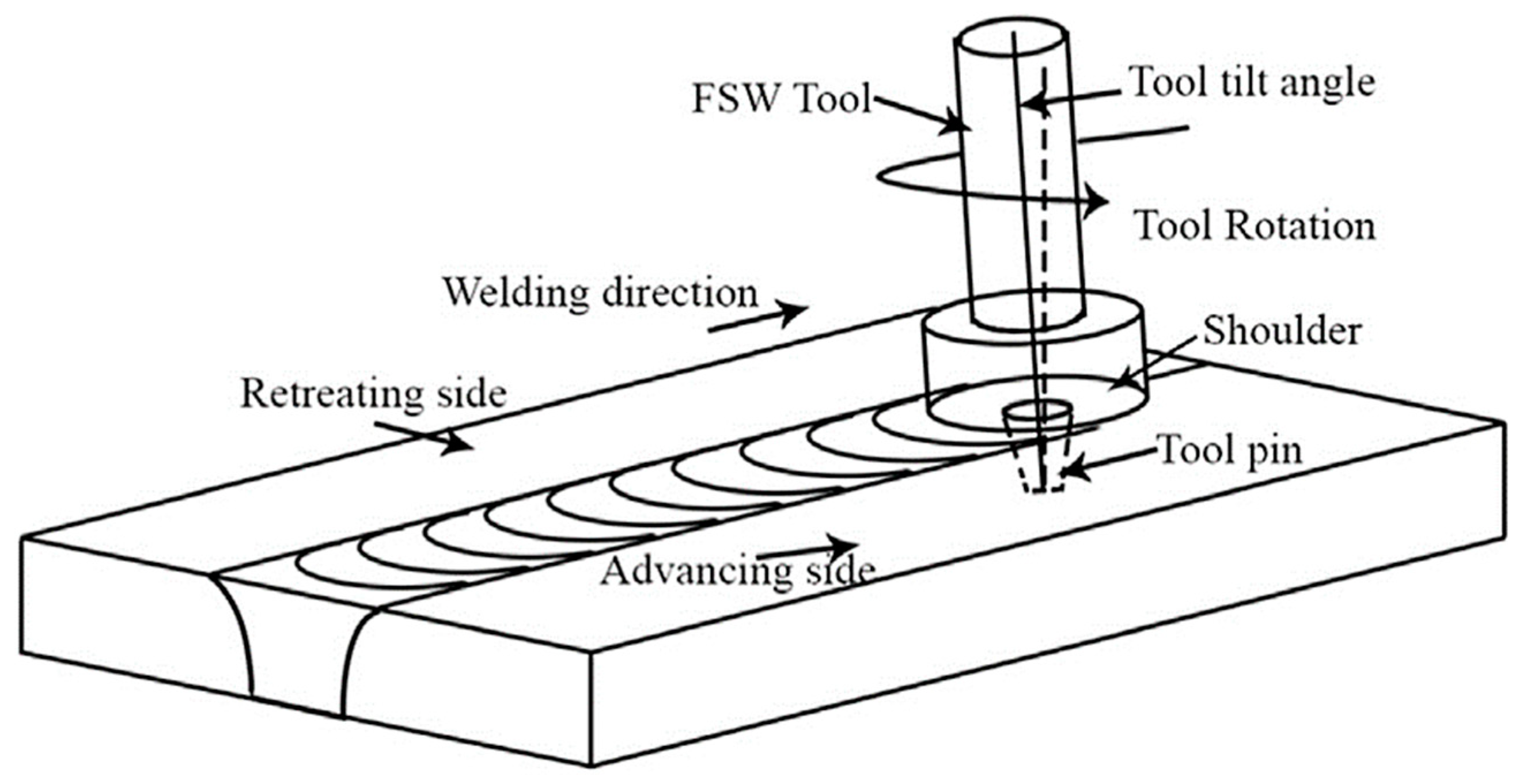
Friction stir welding (FSW) is a widely used solid-state joining process for metals and alloys developed at The Welding Institute (TWI) in 1991. The FSW process, for is used to integrate two metal pieces; the general principles are schematically shown in Figure 1. During the FSW process, a rotating tool is inserted into the interface between two workpieces, which is then traversed along the welding line. The rotating tool is usually composed of a pin and a shoulder. The applied plastic deformation and heat-induced by friction between the rotating tool and workpiece lead to the formation of a solid-state weld [1,2,3,4,5]. Although FSW is applicable for various metals [6,7,8,9,10], it is mostly used in the joining of Al alloys [1,11,12,13,14]. FSW of Al alloys has many advantages compared with conventional fusion welding processes (e.g., MIG and TIG). These include finer microstructure, better dimensional stability, lower processing defects, reduced residual stresses, and superior mechanical properties [3,15,16].
Non-heat-treatable Al alloys, which are also called strain-hardened or work-hardened alloys, include a group of alloys that are usually strengthened via cold work and/or solid solution hardening. The various combinations of additions used for these alloys are shown in Table 1 [3,17,18]. Temper designations for the alloys strengthened by strain hardening consist of an H followed by two or more digits (e.g., AA3103-H13). The first digit following the H indicates whether the strain-hardened alloy has been thermally treated, and the digit following the H1, H2, and H3 (e.g., H1xx, H2xx, or H3xx conditions) indicates the degree of the applied strain hardening. Furthermore, the letter “O” is used to present the annealed conditions by which the lowest strength is achieved [19,20].
Figure 1.
Schematic of the FSW Process [21]. Reprinted from: Quantitative wear analysis of H13 steel tool during friction stir welding of Cu-0.8%Cr-0.1%Zr alloy, Wear 378 (2017): 82–89. Sahlot, Pankaj, Kaushal Jha, G. K. Dey, and Amit Arora, Copyright 2017, with permission from Elsevier.
Figure 1.
Schematic of the FSW Process [21]. Reprinted from: Quantitative wear analysis of H13 steel tool during friction stir welding of Cu-0.8%Cr-0.1%Zr alloy, Wear 378 (2017): 82–89. Sahlot, Pankaj, Kaushal Jha, G. K. Dey, and Amit Arora, Copyright 2017, with permission from Elsevier.


| Non-Heat-Treatable Aluminum Series | Common Alloys (Number) | Alloy System | Tensile Strength Range (MPa) |
|---|---|---|---|
| 1xxx | 1050, 1060, 1100 | Pure Al | 70–175 |
| 3xxx | 3003, 3004, 3105 | Al-Mn | 140–280 |
| 5xxx | 5005, 5052, 5056, 5083, 5086, 5454, 5456, 5657, 5754 | Al-Mg | 140–380 |
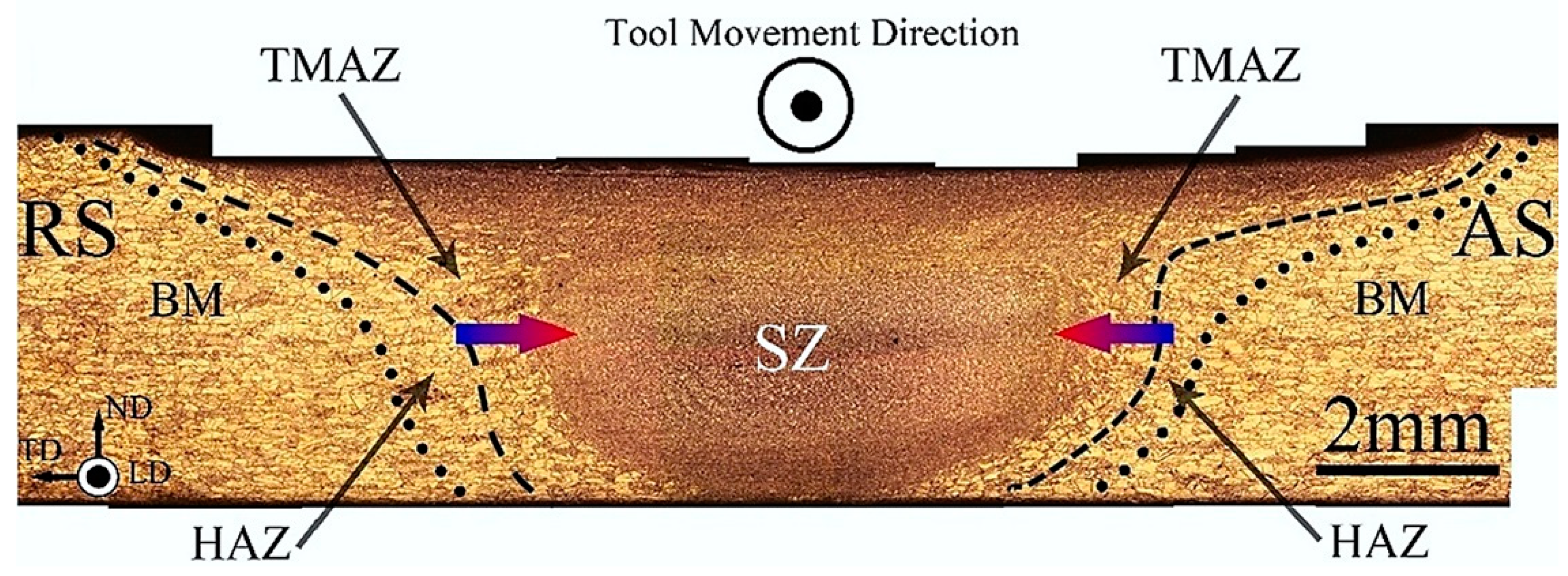
The plastic flow applied by the rotating pin leads to stirring and mixing of material around the weld zone, while friction between the tool and the workpiece provides the main contribution to heat generation [3,22,23]. The generated heat activates softening mechanisms by which the mechanical properties of the weld area are deteriorated compared to the base metal [1,24,25,26,27,28]. Overall, four distinct macrostructural zones can be identified in the FSWed joints, including: heat-affected zone (HAZ), thermomechanical affected zone (TMAZ), stir zone (SZ), and base metal (BM) [29]. Figure 2 shows a common cross-section of FSWed joints [29].
In heat-treatable (e.g., age-hardened) Al alloys, the softening mechanism is associated with the dissolution of strengthening precipitates and grain growth during the welding thermal cycle. Loss of the mechanical properties in this group of Al alloys can be somewhat mitigated by applying subsequent natural or artificial aging treatment [17,26,30,31,32,33]. For instance, Sato et al. [34,35] reported higher density of strengthening precipitates and superior mechanical strength of AA6063 after applying post-weld aging relative to the as-received base metal. Furthermore, Kalemba et al. [36] investigated the FSW of AA7136-T76 under three and six years naturally aged conditions, and stated that natural aging remarkably improved the mechanical properties of FSWed joints of heat treatable alloys.
In non-heat-treatable, work-hardened Al alloys, the softened region leads to considerable deterioration in the tensile properties, hardness, and fatigue resistance of the FSWed joints. Recovery and recrystallization are the principle softening mechanisms [31,37,38]. It should be noted that the FSW process often does not lead to a reducing effect on mechanical properties of the annealed and H111 temper Al alloys. “H111 Temper” Al alloys receive cold-work hardening after annealing but not enough for the alloys to meet the mechanical properties of full work-hardened products such as H11 or H12 temper [19,39,40]. Unlike the heat-treatable alloys, applying the post-weld heat treatment does not work and can significantly deteriorate the mechanical properties of the FSW joints of the strain-hardened Al alloys [17,38,41,42]. Therefore, a comprehensive literature review is required to outline the promising strategies and processing routes that can improve the weld performance, and to identify the optimum process parameters that can provide high quality FSWed joints.
Several efforts have been made to identify and introduce novel processing routes which can improve the mechanical properties of FSWed joints of non-heat-treatable Al alloys. The first practical approach is the optimization of FSW parameters, including rotational and traverse speeds, welding tool geometry, tool tilt angle, and plunge depth. Minimizing heat generation by applying higher traverse speeds and/or lower rotational speeds seems to be a successful solution for alleviating the softening problems. However, there are concerns about insufficient heat generation which can lead to different types of defects in the weld area where the mechanical properties of the joints can be remarkably reduced [1,22,43,44]. Unfavorable residual stress, distortion, and high surface flash are also negative effects of the excessive heat input that mostly affect the fatigue performance of FSWed joints [2,26,45,46]. Therefore, an appropriate combination of traverse and rotational speeds is required to achieve a defect-free joint with minimum heat input.
Another important FSW parameter is tool geometry, which plays a key role in localized heating and material flow and can remarkably influence the tensile properties, hardness, and fatigue life. Designing appropriate tool geometry is necessary to control the heat input of the FSW joint. The common tool pin design consists of a cylindrical and tapered/conical pin that can be with or without thread [12,47,48,49]. By designing an appropriate tool pin design, it is possible to fabricate FSWed joints with symmetrical mechanical properties.
Furthermore, the tool tilt angle is associated with the effective transfer of material from the front to the back of the pin. Its effect on the formation or disappearance of defects, peak temperature, the material flow, and changing the shapes of the nugget zone has also been shown. The tool tilt angle depends on the tool pin design and the degree of its mixing during FSW. In addition, surface defects that are mainly responsible for fatigue crack initiation are affected by tool tilt angle [44,50,51]. The plunge depth is another factor that affects the surface quality of the joints. Plunge depths that are either too shallow or too deep can negatively affect the weld quality (e.g., by insufficient plastic deformation, lack of penetration, local thinning, and excessive flash) [2,27,52].
The incorporation of reinforcement nano- or microparticles in the microstructure of non-heat-treatable Al alloys can improve the mechanical strength of the stir zone, provided that an appropriate ratio of rotational and traverse speeds is chosen. In addition to the rotational and traverse speeds, the number of FSW passes and direction of the multi-passes are important variables that affect the FSWed joint quality in the presence of reinforcement particles [53,54,55]. The reinforcement particles can be ceramic-based particles, that are intrinsically hard, or intermetallic compounds formed in the microstructure by in situ reaction between metal powder and aluminum matrix. The homogeneous distribution of the reinforcement particles in the aluminum matrix is critical to have high strength FSWed joints [56,57].
The use of artificial cooling (e.g., water) during the course of the FSW process can minimize heat input and the associated softening effect [2]. Underwater friction stir welding (UFSW) improves the mechanical properties of joints by preventing grain coarsening in different weld zones, especially in the HAZ. Using water cooling may require revising the welding parameters of the conventional FSW processes (e.g., rotational speed) to obtain high-quality defect-free joints [58,59]. Water cooling media can greatly improve the fatigue performance of FSWed joints by controlling residual stresses and distortions [25,60].
Several other measures have been suggested to improve the quality of FSWed joints of work-hardened Al alloys. Surface defects, which act as the site of fatigue crack initiation, can be removed and replaced by favorable compressive residual stress and applying suitable surface treatments [61,62]. The Bobbin tool FSW was developed to solve the insufficient tool penetration in conventional tool FSW [26,63]. Furthermore, using Cu backing as a cooling agent was introduced to FSW of Al alloys to improve hardness, tensile properties, and fatigue life [64,65]. Double-sided FSW is an efficient method for joining Al thicker plates, which maximizes symmetry and minimizes the root flaws [10,66].
The FSW process can be used in an individual or combined manner to improve the joints’ efficiency and performance. These techniques are thoroughly reviewed in the following sections.
2. Application
FSW is extensively used in many industries (e.g., shipbuilding, marine, aerospace, railway vehicles, and automotive sectors) in joining non-heat-treatable Al-based products [13,67,68,69,70,71]. Although the FSW process is mostly used in butt welds, other joint designs such as spot welds and T-joint welds are also being performed. In most cases, FSW is applied for large-scale products that are welded by setting the workpiece on a worktable. Even though the applications are in a one-dimensional form, the facility is under development to conduct FSW in a three-dimensional form [2,72,73]. The following are some common examples of FSW, which imply the strong need for FSW use in various industrial sectors.
2.1. Marine
One of the main applications of FSW is in shipbuilding, where it is often used for joining the boat’s hulls and its stiffeners, decking, bulkheads, and superstructure made from corrosion resistant AA5XXX aluminum alloys, such as AA5086, AA5454, AA5456, AA5059, and AA5383 AA5083 products [74,75,76]. In addition, the FSW process is used to join honeycomb panels which have been developed with a high noise-absorbing coefficient for the walls of the ship cabin. In shipbuilding construction, prefabricated panels fabricated by FSW lead to reduced problems for retaining highly skilled welders, thus reducing labor costs. [67,68,77,78]. Furthermore, a portable prototype FSW machine has been recently used in manufacturing the bow section of a new type of ocean viewer vessel made from the AA5083-H321 alloy [67,78].
2.2. Aerospace
The various advantages of the FSW process, such as the weight of the structure, the strength of the joint (particularly fatigue performance), and finished cost, led to interest from the aerospace industry [2,78,79,80]. Various joining processes, especially FSW, are performed to join the main structural areas in a transport aircraft, namely fuselage and pressure cabins, wings, and empennage (horizontal and vertical stabilizers). The engineering properties required for these structures are strength, stiffness, fatigue crack growth, fracture toughness, and corrosion [81]. FSW is used in the manufacturing of aircraft (A3xxx Airbus series) for the production of longitudinal joints in the fuselage, links, and central container of the wing [68].
2.3. Railway
The use of FSW is also increasing in the railway vehicle industry and is an ideal process for butt welding of lengthy longitudinal extruded section profiles for high-speed trains [82,83]. In train and tram structures, FSW is now used for roof panels, car-body, and railway wagons, which are made from longitudinal hollow Al extrusions [78,84,85].
2.4. Automotive
The FSW of different Al alloys has been extensively used in the automotive industry for the high-volume production of vehicle components for years due to the high integrity of the technique [51,72]. Among the innovations used in joining aluminum alloy body panels, prototype frames, and structural components in automobiles are FSW and friction stir spot welding (FSSW) [86].
3. Optimization of Welding Parameters
FSW includes complex metal movement and severe plastic deformation through the mechanical (spinning) motion of a rotating tool. The tool rotational speed, traverse speed, tool design, plunge depth, and tilt angle are the major welding parameters that have considerable impact on the material flow pattern and temperature distribution, thereby affecting the microstructures and mechanical properties of joints [1,27,87]. Evidently, the proper selection and adjustment of the process parameters is critical and can remarkably affect the final quality of the FSWed joints.
Based on what was previously discussed for non-heat-treatable, work-hardened Al alloys (i.e., H-temper), the main issue with defect-free FSWed joints is the severe softening effect and deterioration of mechanical properties in the welded joints, especially in the stir zone (SZ). For example, Yazdipour et al. [88] reported that the hardness around the weld line of AA5083-H321 alloys can be reduced to 50% relative to the base metal. In addition, for a defect-free FSW joint of H-temper Al alloys, the mechanical properties of welds are close to the properties of the annealed temper (i.e., O temper) alloys where the yield and tensile strength can be reduced to 75% and 50%, respectively [31,88,89]. Furthermore, the fatigue strength of the FSWed joints can be equal to or less than the base metal, depending on the applied welding conditions [2,43,51,90]. For example, Aydin et al. [91] reported lower fatigue resistance for the FSWed joints relative to the base material, whereas Uematsu et al. [92] demonstrated that the fatigue strengths of the welds can be nearly the same as those of the parent materials.
The softening problem, which is caused by dynamic recrystallization, grain growth, and low-temperature annealing, results from the heat input rising from the frictional motion of the rotating welding tool. Therefore, controlling the amount of heat input is a key factor in reducing the softening effect in FSWed joints [2,26,88,93]. On the other hand, producing a solid and defect-free joint requires adequate heat input. When the amount of heat input is too low, welding defects occur in the joint, and the mechanical properties, such as tensile strength and fatigue resistance, are adversely affected [31,94]. Therefore, in joining the strain-hardened Al alloys using FSW, the welding parameters must be selected so that the heat input is optimized to achieve a defect-free high strength joint [31,38,94,95]. Effects of the main process parameters on mechanical properties of non-heat-treatable Al alloys and possible improvement strategies are discussed in the following sections.
3.1. Effect of Traverse and Rotational Speeds
Tool rotation speed and tool traverse speed are the two principal parameters generating heat during FSW. Depending on the amount of heat input, three types of problems in FSWed joints of H-temper Al alloys can be encountered: (1) softening (high heat input), (2) process defects (low heat input), and (3) distortion and residual stress [43,44,96]. The effects of these shortcomings on joint quality will be discussed in the following clauses.
3.1.1. Softening (High Heat Input)
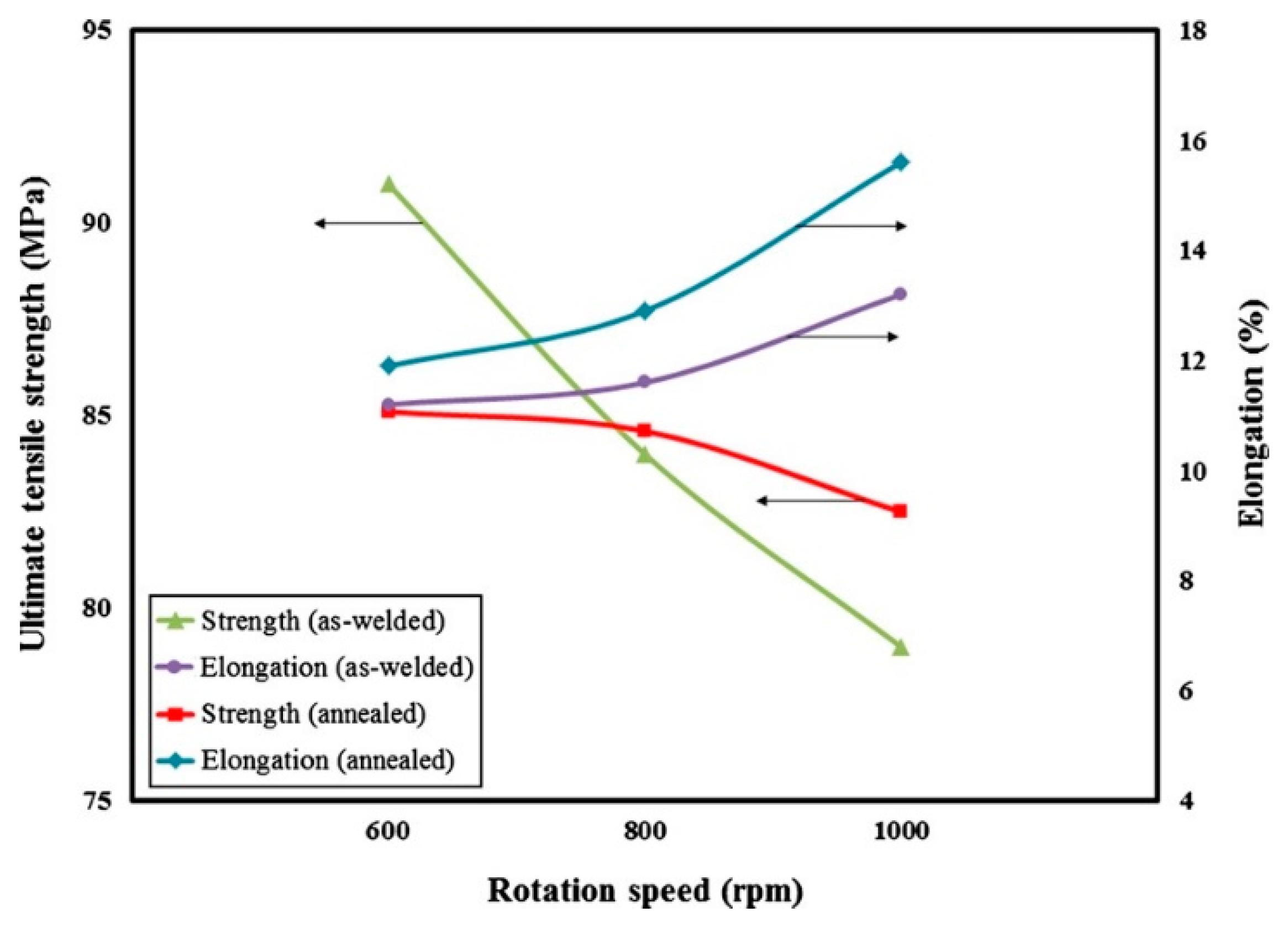
The ratio of “traverse to rotational speed”, which is called revolutionary pitch (RP), controls the heat input to the joint. A higher revolutionary pitch leads to lower heat input in the joint, whereas a lower revolutionary pitch produces higher heat input [31,94,97,98]. As shown in Figure 3, Khorrami et al. [42] indicated that increasing the rotational speed (higher heat input) led to lower tensile strength and larger elongation in defect-free FSWed joints of both work-hardened (as-welded) and annealed 1XXX pure Al alloy [42]. Additionally, an increase in ultimate tensile strength has been reported when the revolutionary pitch increases from 0.07 to 0.47 mm/rpm in the FSW of AA1050-H24 pieces [99]. Therefore, decreasing the rotational speed and increasing the traverse speed leads to an increase in the revolutionary pitch. Subsequently, the amount of heat input reduces under this condition. When the heat input is alleviated, the annealing of the work-hardened Al base is reduced. This is desirable for the strength of the defect-free welds because the softening effect caused by annealing is reduced. The mechanical properties, including tensile strength and hardness, can therefore be improved in the defect-free FSWed joints by rotational and traverse speeds [1,41,97,98].
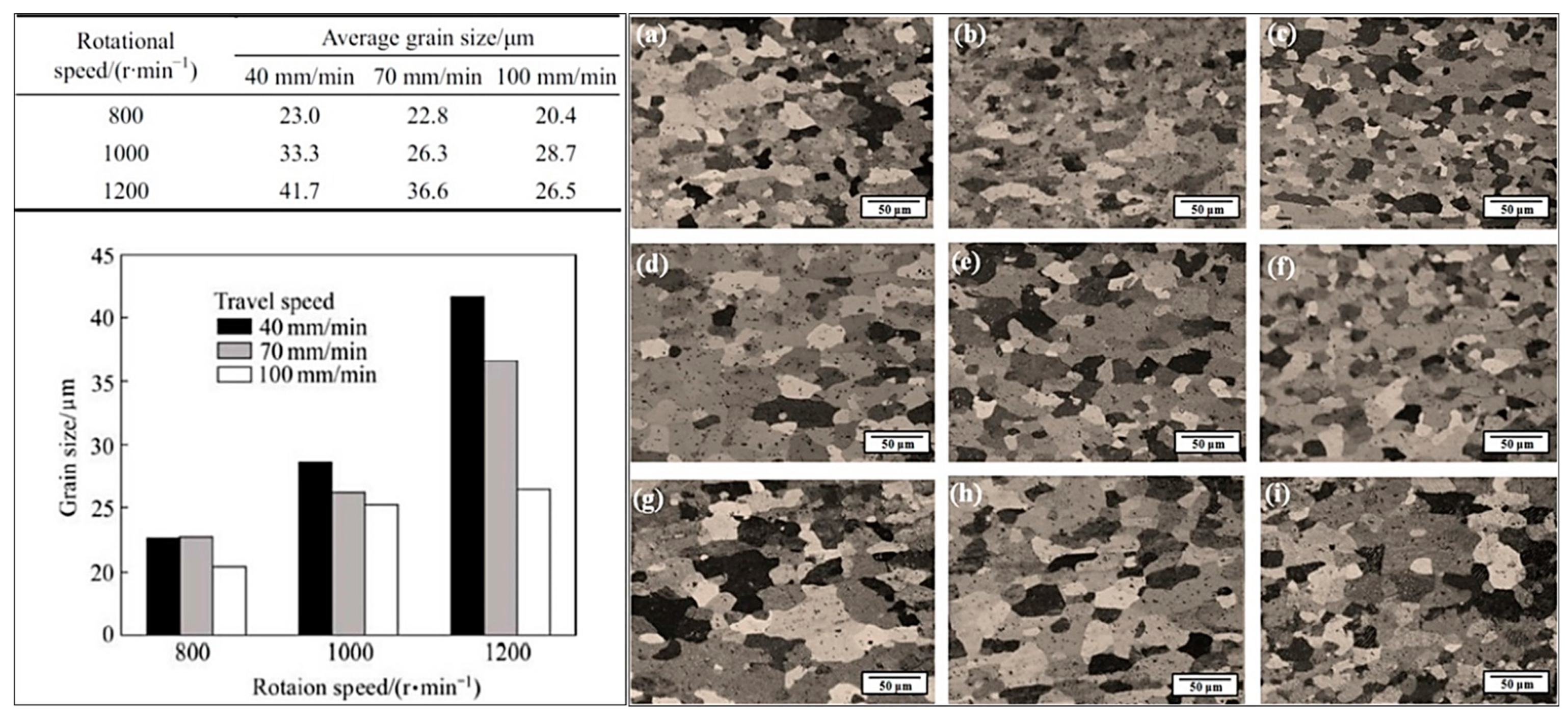
The mechanical behavior of different weld zones (SZ, HAZ, and TMAZ) varies with the heat input induced by traverse and rotational speeds. Several studies on FSW of non-heat-treatable wrought Al alloys have shown that the various traverse speeds at a constant rotational speed do not have a considerable impact on the average hardness value of the stir zone [25,38,94,100]. However, the variation of rotational and traverse speeds not only results in a change in the mechanical behavior of the HAZ, but also influences the softened HAZ width. It has been widely reported that the hardness values of HAZ decrease with decreasing traverse speed and increasing rotational speed [3,31,38,75,96,101]. This combination of parameters (lower revolutionary pitch or higher heat input) results in a wider softened HAZ due to a higher holding time at the peak temperature since the cooling rate is noticeably reduced. Furthermore, the grains also have enough time to grow, leading to a decrease in the average hardness in this region. It is well-known that grain growth leads to a decrease in the hardness value in Al alloys [38,41,88,102,103]. As observed in Figure 4, the average grain size values of HAZ in the FSW joint of AA3003-H18 are remarkably affected by traverse and rotational speeds. The largest grain size (41.7 µm) belongs to Figure 4g with speeds of 1200 r/min and 40 mm/min (i.e., the lowest revolutionary pitch or highest heat input). In contrast, Figure 4c shows the smallest grain size (20.4 µm) at the highest revolutionary pitch [38]. Mohammadi Sefat et al. [103] studied the size of HAZ for FSW of AA5052-H18 and showed that increasing the traverse speed (linear speed) from 63 mm/min to 315 mm/min and decreasing the rotational speed from 2500 rpm to 800 rpm narrowed the size of HAZ (softening area) (Figure 5) [103]. Thus, a controlled combination of the traverse and rotational speeds provides the possibility of reaching a defect-free joint with minimum heat input. Table 2 outlines a list of process parameters which are optimized to achieve high tensile properties in the FSWed joints of non-heat-treated Al alloys.
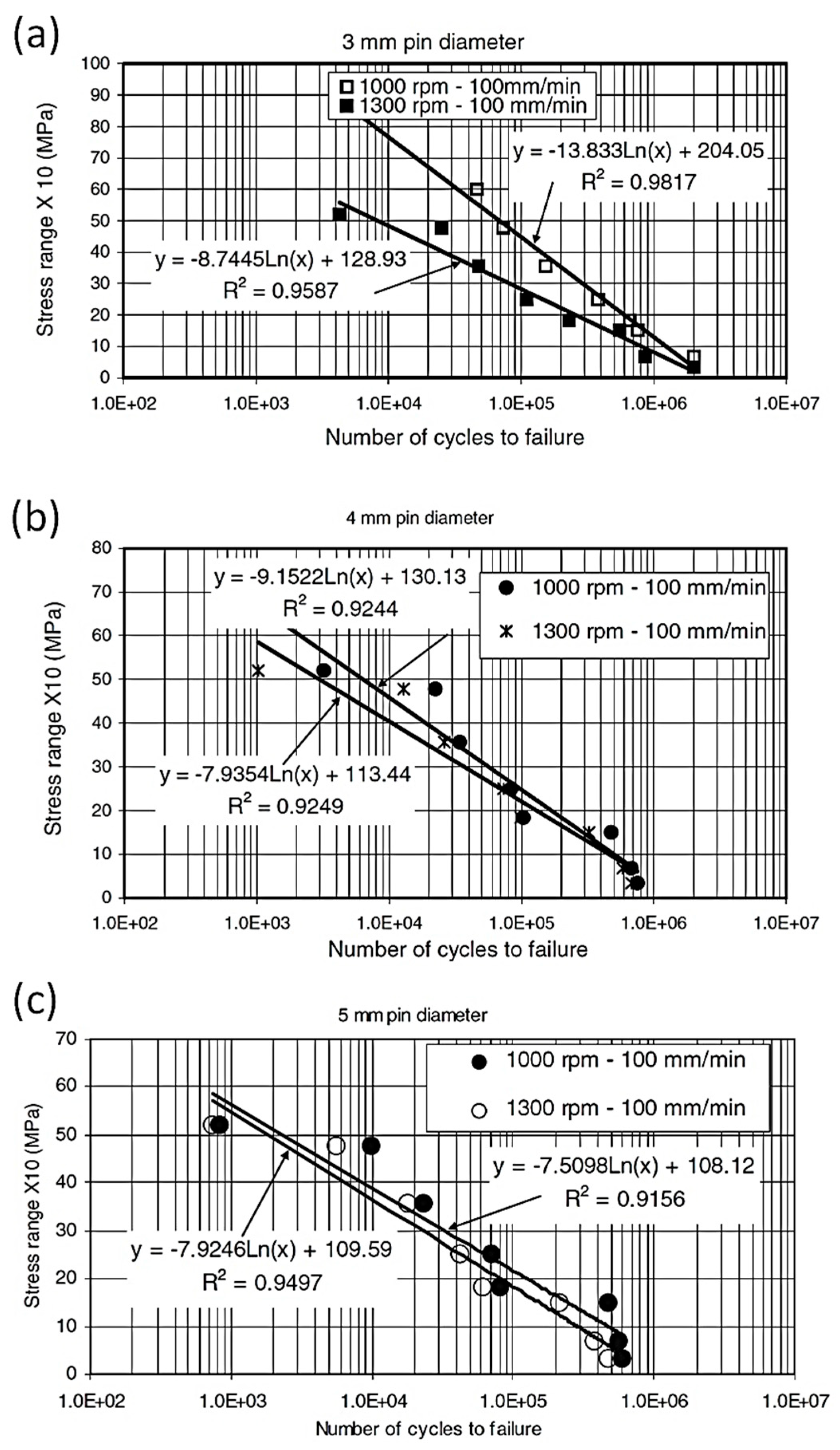
Failure behavior of defect-free FSWed joints under cyclic loading is also influenced by the degree of softening induced with different rotational and traverse speeds [46,108,109]. It is generally believed that fatigue crack is more likely to be initiated by the applied plastic deformation localized in the softened area of the FSWed joints [110,111]. Kulekci et al. [43] reported that increasing the tool rotational speed for a fixed tool pin diameter reduces the fatigue strength of FSWed lap defect-free joints of AA5754 (Figure 6). This reduction in fatigue resistance, as illustrated in Figure 6, is attributed to the heat input and corresponding softening induced in the welding region. Similar to hardness and tensile strength, extreme heat input during the FSW process negatively affects fatigue strength. Therefore, tool rotational and traverse speeds need to be optimized to improve fatigue performance. The rotational speed of 1000 rpm and traverse speed of 100 mm/min have been reported as optimum parameters for AA5754 FSWed joints [43].
Furthermore, the heterogeneity of mechanical properties has been reported for different thickness layers (top, middle, and bottom) of FSWed joints [94,112,113,114]. For instance, Liu et al. [94] indicated that the hardness, ultimate strength, and yield strength of the middle layer were slightly smaller than the upper and lower layers of defect-free joints of AA1050-H24 sheet with a thickness of 5 mm. The lower heat output from the middle layer relative to the upper/lower layers, and the subsequent softening, was responsible for the weaker mechanical strength [94,112,113]. For thinner plates, the mechanical strength of the top, middle, and bottom is closer and more uniform [114]. However, for thicker plates, the heterogeneity of mechanical properties across the plate thickness is expected as the cooling rate and heat output vary from surface layers to central zones. In general, the increase in revolutionary pitch (low heat input) can help to minimize this heterogeneity in defect-free FSWed joints. Process cooling, such as water spray or underwater FSW, is another method for reducing the heterogeneity across the plate thickness, which is described in Section 5.
3.1.2. Defects (Low Heat Input)
High traverse speed and low rotational speed may result in an inappropriate joint due to low heat input and the formation of defects in the weld zone [44,91,115]. The values of these high and low speeds are not specific and depend on several parameters, such as the thickness of the workpiece, the design of the welding tool, the backing material, the title angle, and the plunge depth. For defect-free joints, the tensile properties are most likely correlated with the hardness values distributed across the weld. On the other hand, for defective joints, the tensile properties (e.g., ultimate tensile strength, yield strength, elongation, and fracture location) of the joints are primarily affected by defects such as cracks, voids, tunneling, surface imperfection, hooking, flashes, and kissing bonds or zigzag lines (Al2O3 oxide layer) [44,109,116,117]. The presence of a defect in the stir zone not only causes a significant reduction in elongation, but also results in a deterioration of the tensile and yield strength of the FSWed joints. Moreover, in a defective weld, fracture locations are often located in the stir zone where cracks are initiated [31,95].
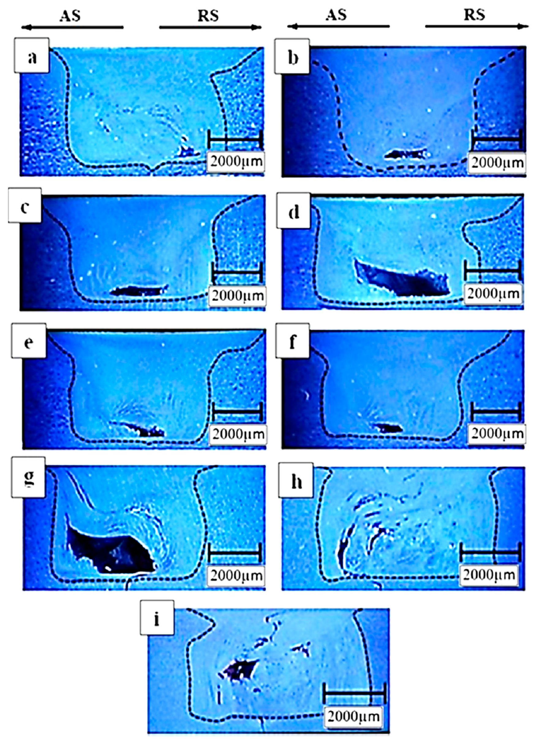
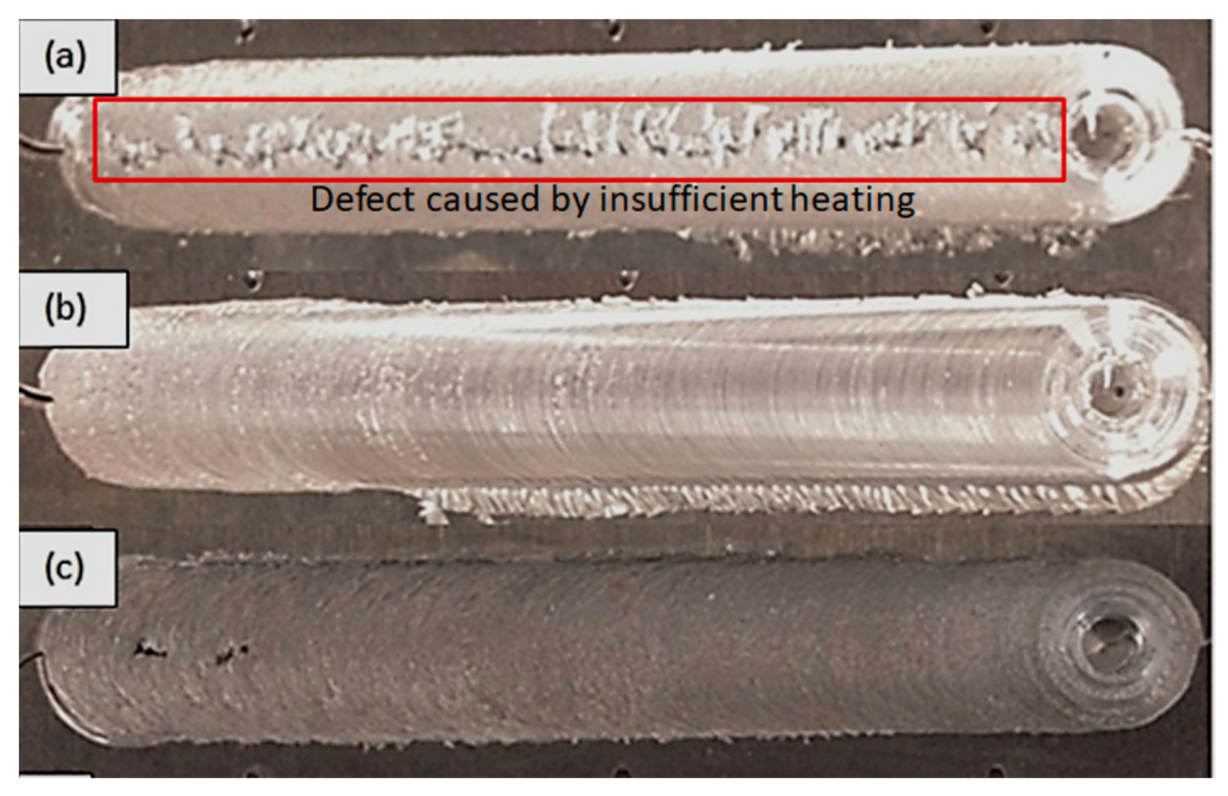
It should be noted that both insufficient and excessive heat input can lead to process defects in the joints [118]. According to the Han et al. study on the FSW of AA5083-O [95], when the rotational speed of the probe was too high, the peak temperature was stabilized. Therefore, more pressure on the probe shoulder became ineffective and led to a defect in the welded joint through chip formation. Based on their report, the optimum FSW conditions were a welding speed of 124 mm/min and a rotational speed of 800 r/min for AA5083-O [95]. In addition, Jamalian et al. [106] indicated that both low (500 and 800 rpm) and high (1600 rpm) rotational speeds at various traverse speeds (41.5, 80, and 125 mm/min) led to tunneling and wormhole defects in the FSWed joints of AA5086-H34. However, FSW at rotational speeds of 1000 and 1250 rpm showed a defect-free weld. Figure 7 shows the macrostructure of the defective joints obtained with different rotational speeds in their work. Figure 7a–f shows tunneling and wormhole defects at low rotational speeds, which were caused by insufficient heat generation and poor plasticity flow. At rotational speeds that were too high, these defects were generated as a result of considerable turbulence in the plasticized metal, as shown in Figure 7g–i [106]. Moreover, Javad Rasti [119] studied the welding parameters’ effect on the tunnel void area during a FSW of AA1060 at different rotational (500 and 1000 rpm) and traverse (250, 500, 650 mm/min) speeds. According to his findings, the area of tunnel cavity defect was zero for a rotational speed of 1000 rpm and traverse speed of 250 and 500 mm/min [119]. According to various works on FSW of non-heat-treatable Al alloys, it is concluded that the optimum rotational speeds are approximately 1000 rpm to achieve a defect-free joint, but the optimum traverse speed varies for different alloys. For example, in order to obtain a defect-free joint, 5xxx Al alloys generally need higher heat input caused by lower traverse speed compared to the 1xxx Al alloys [120]. This can be attributed to the mechanical properties and different flowing behavior of base metals. In high-strength Al alloys, such as AA5083 (275–385 MPa), it takes more time to reach the desired heat input and temperature for stirring materials. Therefore, the transverse speed should be slow. However, AA1060 requires lower heat input because of the lower tensile strength (55–130 MPa).
One of the main factors that influence the fatigue behavior of joints is a weld defect. Although the high traverse speeds and low rotational speeds (low heat input) are helpful to control residual stresses and distortion, there is concern about the formation of weld defects under this process condition, which can reduce fatigue life [44,91]. Process defects accelerate the fatigue crack initiation and propagation, which are the main contributors to the sudden decline of fatigue life in the weld joints [2,46].
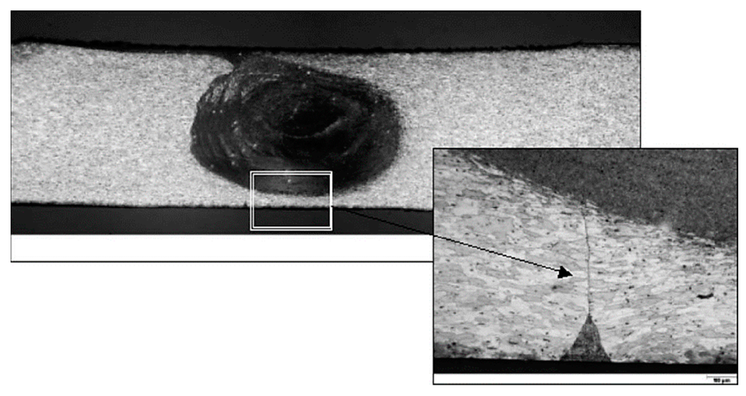
A continuous S-shaped line in the stir zone is called S-line, zigzag line, or kissing bond, which is mainly formed by the accumulation of the fine oxide particles resulting from the initial oxide layer on the butt surface [110,121]. Sato et al. [122] investigated the characteristics of the kissing bond defect on FSW of AA1050-H24. They reported that welding parameters have a substantial effect on the formation of the kissing bond. For example, the higher the welding heat input, the lower the kissing bonds (as shown in Figure 8). At the lower heat input, the distribution of the oxide layers is weakened, and they appear with localized accumulation in the microstructure. The oxide layers at the higher heat input can be broken, homogeneously distributed in the microstructure, and do not adversely affect the mechanical properties of the joints [51,109,122]. Zhou et al. [109] studied the effect of the kissing bond on the fatigue behavior of FSW on AA5083-H321. They concluded that the kissing bond (bonded welds) accelerated the crack initiations under fatigue loading, and subsequently, the fatigue life of the joints containing kissing bonds was 21–24 times shorter relative to the sound welds [109,123].
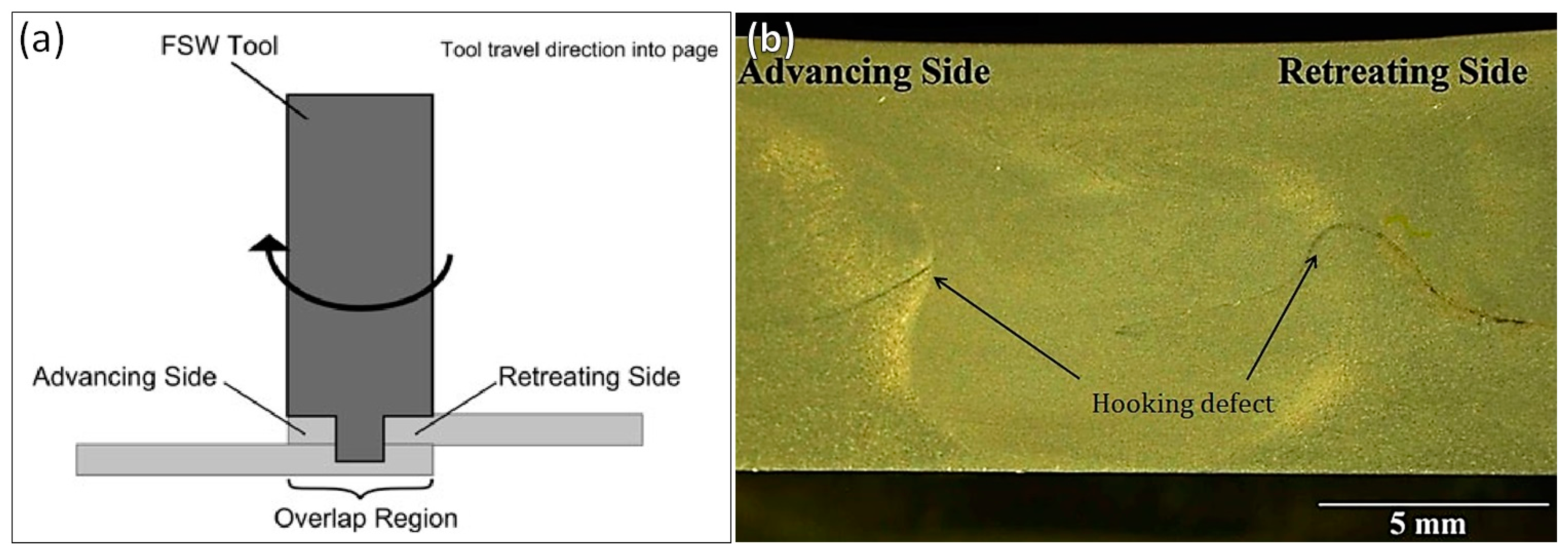
Apart from the defects observed in butt welds, friction stir lap welding (FSLW) also has special features at the edges of the bonded region, which is called a “hooking defect” [2]. In lap joints, one sheet is laid on top of another, and a slight overlap region is created. The FSW probe plunges completely through the upper sheet and slightly into the lower sample, traversing through the overlap region [124,125,126]. A schematic of the FSLW process is shown in Figure 9a. Shirazi et al. [127] observed such defects in their study on the FSLW of AA5456. Figure 9b shows an example of the hooking defect on both the advancing and the retreating sides of the joint conducted on 5 mm thick AA5456-H321 and 2.5 mm thick AA5456-O. According to their findings, the height and shape of the hooking were affected by rotational and traverse speeds [127]. Increasing the rotational speed enhanced the vertical material flow, leading to an increase in the hooking height. At a constant rotational speed, the height and direction of the hooking changed with the increase of the traverse speed. At low rotational speeds, the increase in the traverse speed resulted in decreasing the hooking height on both the advancing and retreating sides due to less vertical material flow [127]. Moreover, Salari et al. [128] suggested that a larger hooking defect had a more negative impact on the mechanical properties of FSLW AA5456. They also reported that an increase in rotational speed was a reason for increasing the hooking defect height [128].
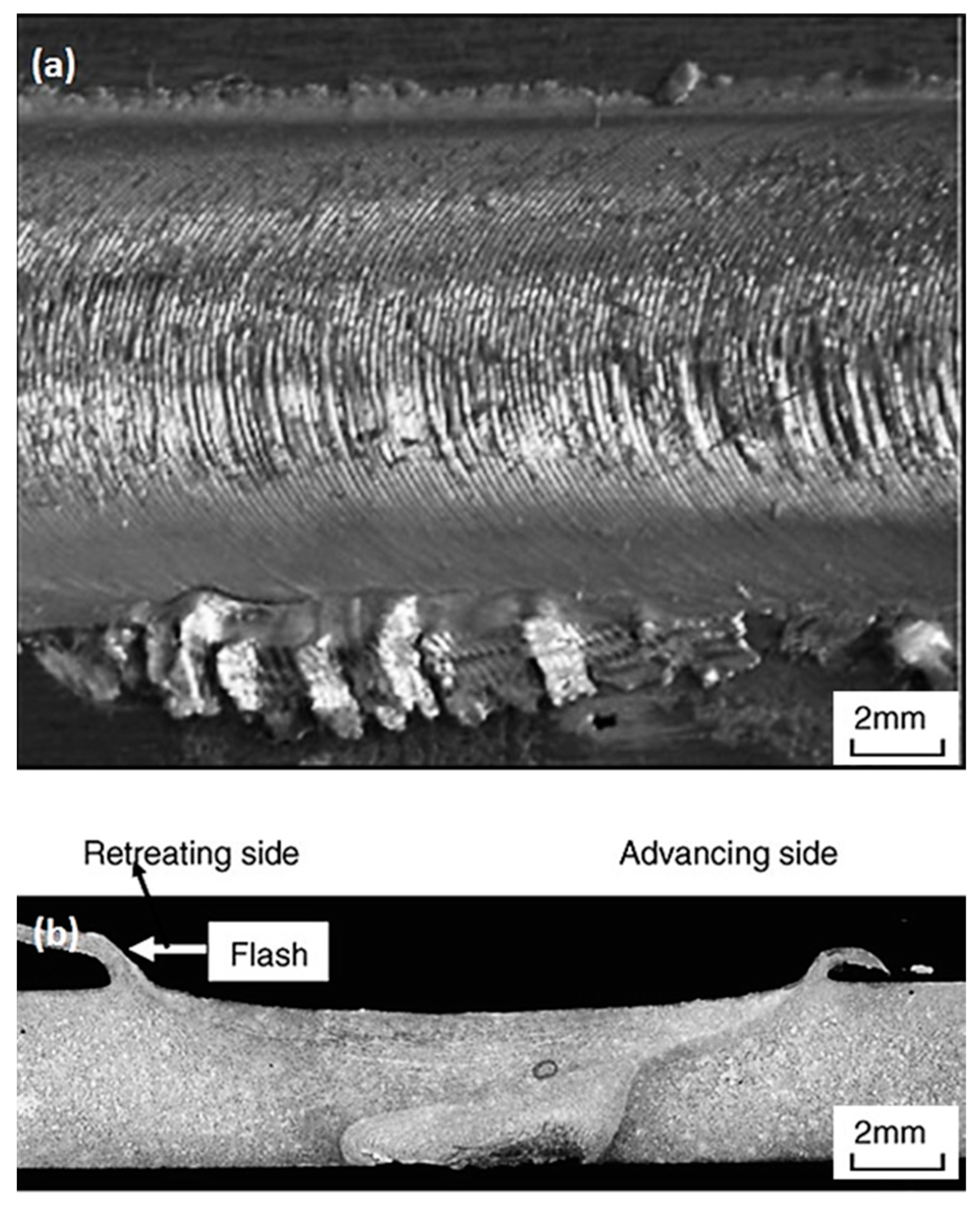
Lomolino et al. [61] reported that fatigue failures of FSWed joints of Al alloys were initiated at surface roughness or the surface flash of the joint. Figure 10 illustrates the typical surface defects in the FSWed joints. Based on their results, the fatigue failure of the joints was initiated from the notches introduced by pronounced lips or tool marks on the weld surface [61]. Accordingly, from the perspective of roughness, surface defects, and volumetric defects, the lower traverse speed and higher rotational speed provide the best fatigue performance due to the defect-free welds with smooth surfaces [46,96,129]. Nevertheless, there are also conflicting reports that the excess heat input, caused by the lower traverse speed and high rotational speed, may result in a large mass of flash on the surface [2,115,130].
3.1.3. Distortion and Residual Stress
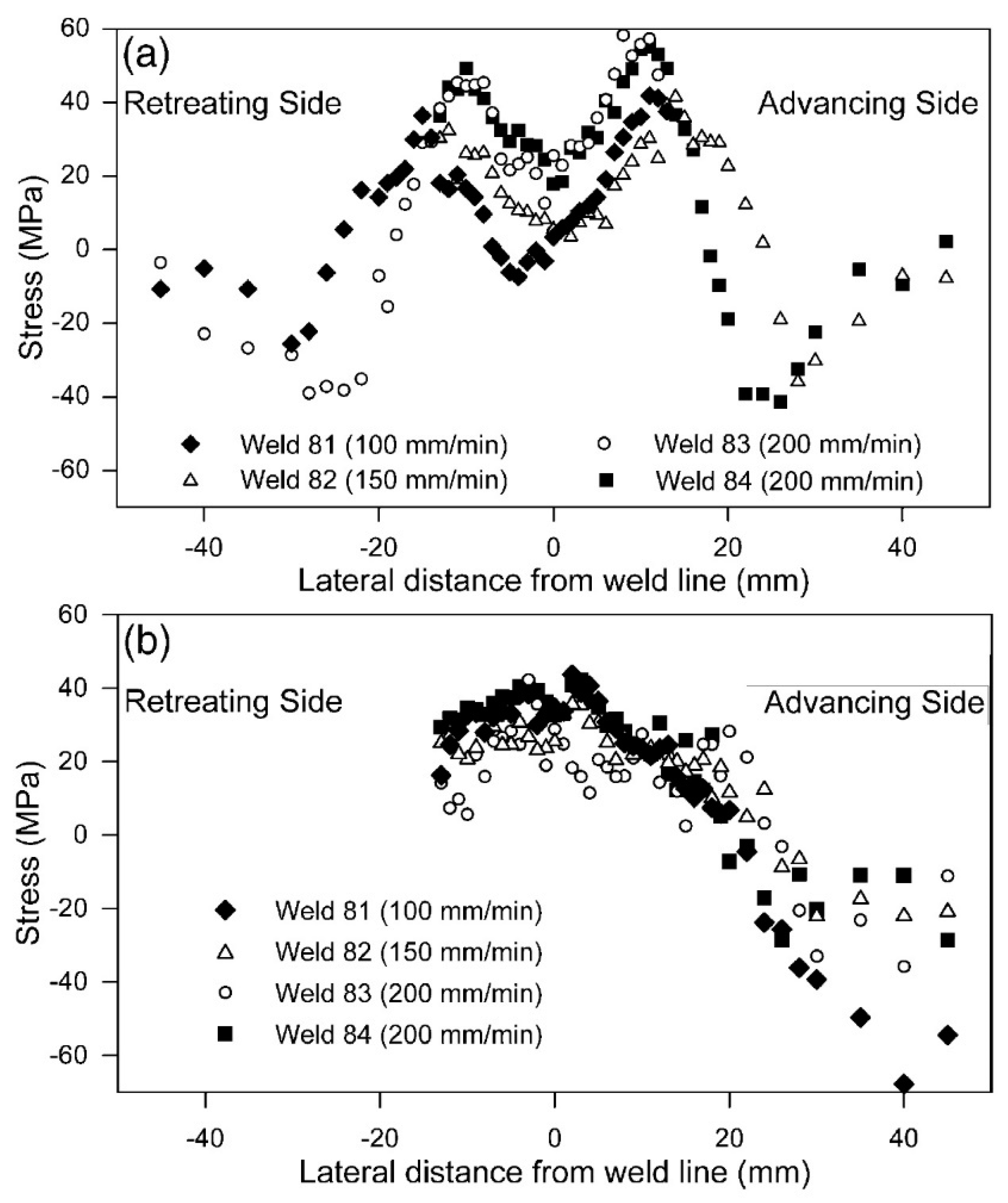
It is well accepted that the residual stress and microstructure evolution for defect-free FSW joints affects the fatigue crack initiation [45,110]. Kulekci et al. [131] reported the detrimental impact of increasing rotational speed for the fatigue life of FSWed AA1050-H18 joints. For a defect-free FSW joint, excessive heat input leads to higher residual stresses and distortion, which are generally unfavorable factors for fatigue performance. Lombard et al. [60] investigated the effect of different rotational and traverse speeds (varied heat input) on the residual stress profiles in FSWed AA5083-H321 joints. They reported that the residual stresses were generally in tensile mode in the weld region. Moreover, the size of the residual stress area and maximum residual stress had a clear correlation with the heat input (i.e., the greater the heat input per unit length, the broader the residual stress profiles) [60]. Peel et al. [25] indicated that the residual stress distribution was associated with the welding speed in AA5083 FSW joints. As shown in Figure 11, by increasing the traverse speed, the peak stresses were formed adjacent to the weld line, implying a reduction in heat input. This led to a reduction in the width of the high-temperature zone around the tool [25]. Under this condition, the width of the high-temperature zone shrank, and the tensile stresses were reduced and limited to the softened weld zone. Thus, the higher the traverse speed (i.e., the lower heat input per unit length), the lower the distortion and residual stresses, and consequently, the better the fatigue performance [25,51,96].
FSW with improper welding parameters can result in a reduction in crack initiation life and fatigue strength due to the residual stress which affects crack growth across the weld line. Under compressive residual stresses, fatigue cracks are initiated, but the subsequent crack propagation is reduced, which leads to lower fatigue crack growth rates. However, the tensile residual stress accelerates along with the crack growth rates. Accordingly, fatigue cracks can be propagated if the crack length reaches the minimum threshold for growth under tensile stresses; in that case, the fatigue strength of the FSWed joint is reduced [2,45,51,110]. It is also worth mentioning that the wider, softened HAZ, induced by the higher heat input, adversely affects the fatigue performance of FSW due to higher distortion and stress concentrations [2,51,132].
3.2. Effect of Tool Pin Geometry
Tool geometry is one of the main process parameters that play a vital role in material flow and FSWed joint quality. The frictional heat generated during the mechanical stirring of the FSW process is correlated with the tool design [79,105,133]. The size of the weld zone (including SZ, HAZ, and TMAZ) and possible process defects are affected by tool geometry. Subsequently, apart from the rotational and traverse speeds, tool geometry critically influences the mechanical performance of FSWed joints in non-heat-treatable Al alloys [1,10,27,128]. The proper design of tool geometry, along with optimal welding parameters, can lead to sound and defect-free FSWed joints in H-temper Al alloys.
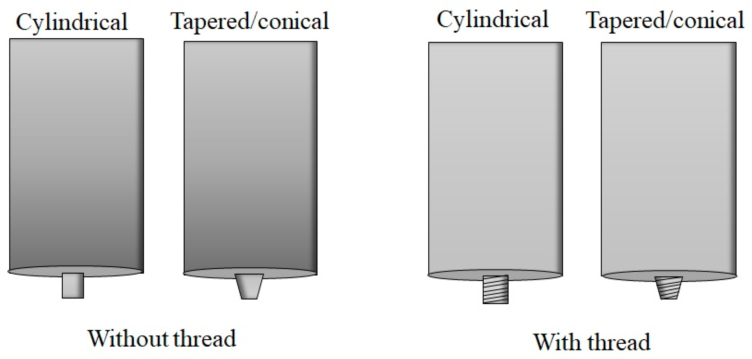
The tool geometry consists of a shoulder and a pin which have two primary functions: localized heating and material flow [1,134]. There are various tool pin shapes for the FSW process. As shown in Figure 12, the most common pin shapes for FSW of non-heat-treatable Al alloys are divided into two categories: cylindrical (with or without thread) and tapered/conical (with or without thread). In some cases, these types of tool pins are designed with flutes [47,48,135,136,137,138].
The impact of the pin threads on the FSWed joint quality was the basis of several research studies for non-heat-treatable Al alloys [99,137,138,139,140,141,142,143,144]. Fuji et al. [137] reported that, when the threaded cylindrical tool pin was used, the traverse speed of more than 300 mm/min (revolutionary pitch 0.2 mm/rpm) led to a crack-like defect in the FSWed joints of AA1050-H24, which remarkably reduced the tensile properties. However, FSW with the unthreaded tool pin resulted in defect-free welds and increased the strength in the studied range of the traverse speed (100–700 mm/min). Chandrashekar et al. [138] performed FSW on AA5083-H111 with three rotational speeds (600, 800, and 1000 rpm) and a constant traverse speed of 50 mm/min with tapered threaded and tapered unthreaded pins. According to their report, using the tapered threaded pin resulted in higher hardness and tensile strength for rotational speeds of 600 and 800 rpm compared to the tapered unthreaded pin. However, the FSW of AA5083-H111 with the tapered threaded pins at a rotational speed of 1000 rpm demonstrated lower hardness and tensile strength compared to tapered unthreaded pins [138]. Similar mechanical behavior has been reported by Kumar et al. [143] for FSW of AA5083 using both threaded and unthreaded tapered tool pins. Based on their efforts, the tensile strength of joints, welded by a threaded pin, was higher than the strength of unthreaded tool pins for rotational speeds of 900 and 1120 rpm. For higher rotational speeds (1400 and 1800 rpm), the tensile strength of joints welded by threaded pins indicated unfavorable results compared to unthreaded tool pins [143]. It has also been reported by [141] that the threaded pins at rotational speeds up to 1300 rpm made sound FSWed joints in the work-hardened AA1060 alloy.
The effect of using a threaded tool pin on various grades of non-heat-treatable Al alloys can be slightly different, but it can be generally advised to use a threaded tool pin for lower rotational speeds; according to several studies on FSW of non-heat-treatable Al alloys [48,137,138,143], using threaded welding tool pins (both taper and cylindrical shape) is only recommended when the rotational tool speed is less than about 1000 rpm. The threaded tool pins can result in FSWed joints with superior mechanical properties compared to joints welded using unthreaded tool pins. Using threaded tools for higher rotational speeds compromises the quality of the weld with defect formation in the stir zone as it generates severe turbulence in the material flow. Furthermore, using threaded tool pins is not advisable for FSW of strain-hardened Al alloys at high traverse speeds as it may provoke crack-like defects in the stir zone.
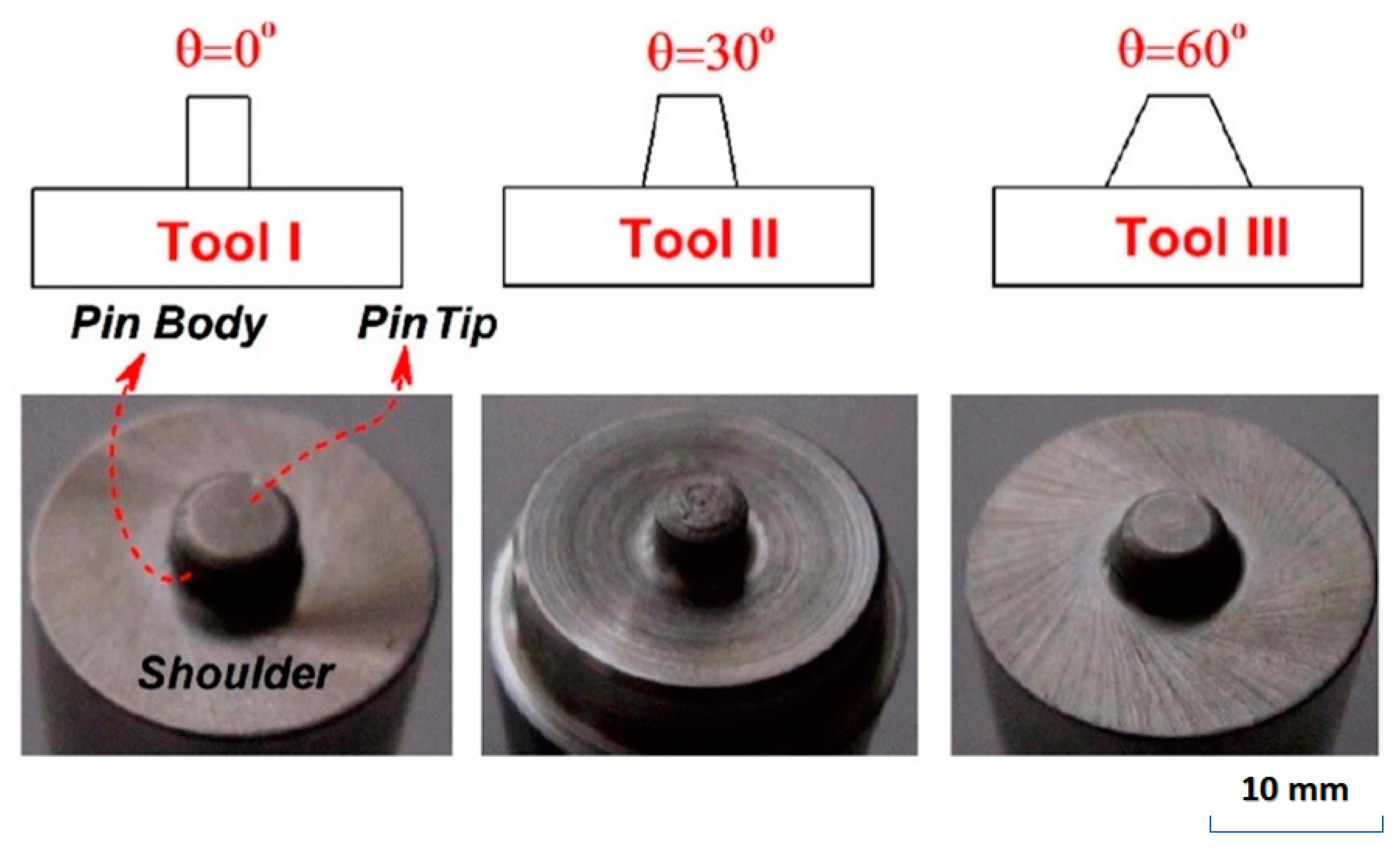
The effects of taper tool pins and their angle on the FSW of non-heat-treatable Al alloys have been widely studied [48,139,140,141,142,145]. Janeczek et al. [48] explored the influence of cylindrical threaded and tapered threaded tool pins on the mechanical properties of AA3004 FSWed joints. Based on their work, the cylindrical threaded and tapered threaded pins achieved a tensile strength of 198 MPa and 71 MPa and elongation of 12% and 3%, respectively, under the same welding conditions (welding speed 235 mm/min, rotational speed 475 rpm). The obtained mechanical properties were associated with proper heating and plastic deformation in joints processed by the cylindrical threaded pin, and voids formation in the joints made by tapered threaded pins. Due to the tapered shape of the pin and insufficient heat generation, the material could not be stirred well to obtain a consistent joint [48]. In contrast, Chupradit et al. [136] demonstrated that the higher mechanical works and lower heat generation of the high angle unthreaded tapered pin plays a positive role during the FSW process of 4 mm thickness AA5058 compared to the cylindrical one. As observed in Figure 13, they performed FSW with three tool pin designs and studied pin taper angle thermal effects of defect-free FSWed joints at the tool rotational and traverse speeds of 850 rpm and 30 mm/min, respectively. They observed the lowest temperature in both advancing and retreating sides of the defect-free joint when tool III (higher angle tool-Figure 13) was used [136]. It is considered an advantage if a defect-free joint is welded with a minimum temperature and heat generation due to its adverse effects on mechanical properties. The proper function of the unthreaded tapered pin on friction stir lap welding of AA5754-H22 thin sheets was observed by Costa et al. [140]. Unlike Chupradit et al., they reported that a tool pin with a lower taper angle (30°) resulted in better fatigue performance of FSLW of AA5754-H22. By using a tool pin with a lower taper angle (30°), the hooking defect, which is a common defect for FSLW, disappeared [2,140]. According to the literature review discussed above, the unthreaded tapered/conical pins provide better weld quality compared to unthreaded straight cylindrical tool pins in FSW of non-heat-treatable Al alloys, whereas the threaded tapered pin design is not recommended as it generates void defects. In addition, the appropriate angle of unthreaded tapered pins depends on joint type. For FSLW, the lower angle is helpful to control the hooking defect formation. The hooking defect is detrimental to the fatigue performance of the joints as it generates favorable conditions for crack initiation, growth, and propagation.
The asymmetric nature of the FSW process, caused by different strain rates and temperatures, has been widely reported. This phenomenon leads to stress concentration and distortion in the workpiece, and subsequently results in undesirable mechanical properties, especially fatigue performance [3,38,106,139,146,147]. Murshid Imam et al. [147] indicated that the temperature and effective strain distribution are higher and wider, respectively, on the advancing side (AS) than on the retreating side (RS) during the FSW of AA5086. The non-uniform distribution of microstructure and hardness during FSW of AA5086 has also been reported by Aval et al. [148]. Developing a suitable tool geometry can reduce this non-uniformity. For instance, Chupradit et al. [136] proposed that the internal heat distribution at a higher pin taper angle (60°), as shown in Figure 13, is symmetrical. In addition, a thermo-mechanical model was adopted by Zhang et al. [149] to investigate the effect of shoulder size on temperature distributions and material deformations. Based on their findings, the temperature distribution was nearly symmetric to the welding line when larger shoulder diameters (24 mm) were used; for the shoulder diameter of 16 mm and 20 mm, the temperature distribution was asymmetric [149].
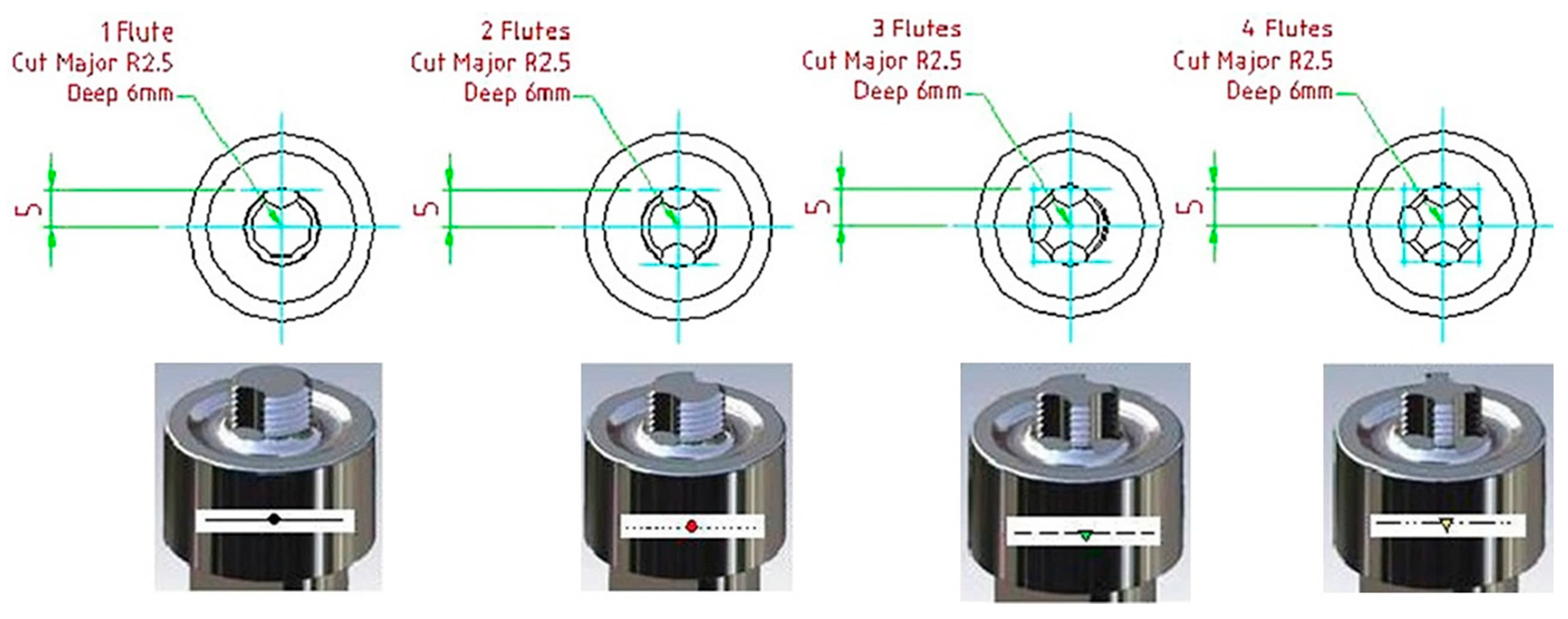
The effect of flute tool pins on the quality of FSWed joints has also been another area of interest. Figure 14 displays examples of 1-flute, 2-flute, 3-flute, and 4-flute FSW tool pin designs [150]. Based on published results [12,47,51,138,150], the 3-flute pin has a better design relative to the other pin profiles. The joints produced with the 3-flute pin showed a suitable material intermixing and finer recrystallized grains in the stir zone resulting in better mechanical properties and joint efficiency. For instance, Kalemba-Rec et al. [47] reported that using the 3-flute pin not only led to a wider stir zone area, but also improved the tensile strength and weld efficiency (above 100%) compared to the threaded taper pin for FSWed joints of dissimilar 7075-T651 and AA5083-H111 [47]. However, optimized tool design is crucial if defect-free welds using a 3-flute pin are to be achieved. Hattingh et al. [150] noticed that the optimum tool design included three tapered flutes, a pin diameter taper, and a thread with a pitch of around 10% for the pin diameter and 15% for the plate thickness [150].
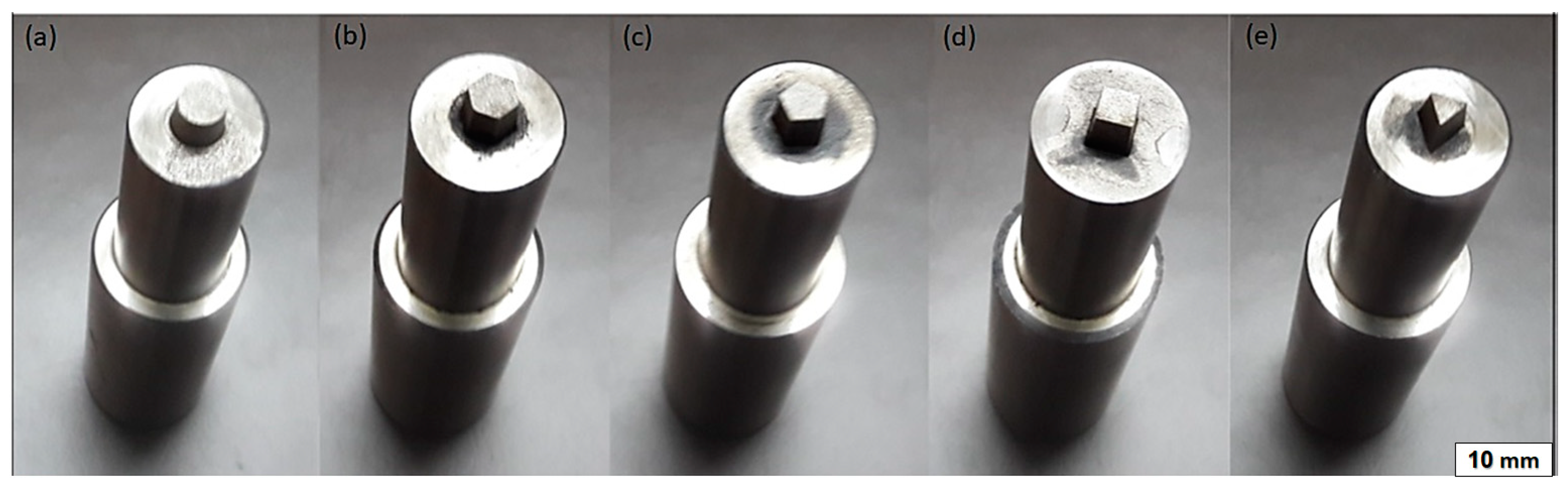
A few studies have also been conducted on other tool pin shapes, such as triangular, square, octagonal, hexagonal, and pyramidal, in the FSW of non-heat-treatable Al alloys [105,133,135,151,152]. Sagheer-Abbasi et al. [105] worked on the optimization of parameters for micro FSW of AA5052 using three tools with different geometries; square, triangle, and circle. They found that the square tool was the best among the examined tool profiles with respect to the weld strength (80% of base material) and production of defect-free joints [105]. Additionally, Shamsudeen et al. [133] similarly suggested that the tapered square tool pin profile could produce higher quality FSWed joints of AA5052 H32 compared to other tool designs, such as the hexagon, pentagon, cylinder, and triangle (Figure 15). Based on this research, the square pin tool results in finer grain size in the stir zone and consolidation of the material under the shoulder, leading to high-quality joints and superior tensile properties. Overall, the application of such tools has often been observed in friction stir processing for making sound aluminum matrix composites (AMCs) with uniform and refined microstructure [153,154,155,156].
Zhang et al. introduced a new approach to improve the mechanical properties of FSWed joints of ultra-thin AA1060 sheets with the shoulderless tool [157]. They reported that the shoulderless tool had advantages such as lower heat input, and provided better mechanical properties, with a welding speed of 140 mm/min and 11,000 rpm compared to conventional tools [157]. Nevertheless, the shoulderless tool cannot be a suitable option for thick sheets due to low friction and insufficient heat generation. As previously mentioned, the shoulder of the welding tool plays an essential role in heat generation and appropriate material flow.
Furthermore, the pin diameter of the welding tool has also been found to be an effective factor in the mechanical properties of FSWed joints [12,43]. The results of pin diameter variation on fatigue properties of FSWed lap joints on AA5754 Al alloy showed that increasing tool pin diameter for a fixed tool rotation decreased the fatigue strength of joints [43].
3.3. Effect of Tool Tilt Angle and Plunge Depth
Tool tilt angle relative to the workpiece surface is another important FSW process parameter that should be considered for producing defect-free joints with better mechanical properties and fatigue life. A proper tilt angle moves material efficiently from the front to the back of the pin and prevents the formation of weld defects [1,44,50,158]. Barlas et al. [129] indicated that changing the tool tilt angle and tool rotation direction with the same tool geometry resulted in different weld nugget zone shapes in AA5754 FSWed joints [129]. In addition to the tool geometry, a right tool tilt angle can lead to better symmetry in the weld area, which results in lower distortion and stress concentration and higher fatigue resistance.
Chekalil et al. [158] investigated the effect of tool tilt angle (i.e., 0.5, 1.5, 2.5°) on the mechanical behavior of FSWed joints of AA3003 alloy. The results showed that the tensile and yield strengths of the welded joints with a tool tilt angle of 0.5° and 1.5° were slightly different; however, increasing the tool tilt angle to 2.5° led to a considerable decrease in the tensile and yield strengths [158]. Furthermore, the effect of tilt angle on microstructure and mechanical properties of dissimilar AA5083 and AA6061 FSWed joints demonstrated that the tilt angle of 3° led to the optimal hardness and microstructure results. The lower tilt angle (0–2°) resulted in a tunnel defect, and the higher tilt angle (4°) caused grain growth and dissolution of strengthening precipitates in AA6061 [159]. Furthermore, Dialami et al. [50] observed that the tool tilt angle increased the temperature in the weld area and facilitated the material flow [50].
Based on these studies, to produce high-quality FSW joints in work-hardened Al alloys, the specific tool tilt angle cannot be generalized to all cases. The tool tilt angle highly depends on the tool pin design. For instance, the volume of the stirred material by the threaded or unthreaded pin is different and needs a suitable tilt for holding stirred materials with the shoulder and then moving material efficiently from the front to the back of the pin. The threaded pins can effectively facilitate the mixing of materials and expand the material flow zone, which improves the mechanical properties [2,27,160]. Consequently, irrespective of other welding parameters, threaded pins demand a higher tool tilt angle compared with unthreaded pins. The tool tilt angle is responsible for a circle of corrugated friction surface defects [44]. Surface defects are often the site of fatigue crack initiation. The appropriate tool tilt angle creates a suitable corrugated arrangement and smooth weld surface with sufficient roughness, which improves fatigue performance [44].
Moreover, the plunge depth, which is associated with the pin height, is important for producing sound welds with a smooth surface. If the plunge depth is too shallow, the shoulder of the tool does not contact the workpiece surface efficiently. Subsequently, the material cannot be sufficiently plasticized and stirred on the complete surface of base metals, resulting in the generation of welds with inner channels or surface grooves. The heat generation in the process is due to the frictional action deriving from the contact between the tool and the workpieces. Thus, it is essential to ensure that the heat available during welding is sufficient to soften the base metal and progress it to a stage where it can flow. On the other hand, if the plunge depth is too deep, the higher amount of heat input can cause some process defects, such as local thinning of the welded plates and excessive flashes, to be formed. These process defects compromise the mechanical properties, especially in cyclic loads [1,27,48,52]. A high tilt angle usually leads to extreme shoulder plunge depth, which is the main reason for weld thinning and excessive flash in FSWed joints. It is destructive to joint integrity, leading to stress concentrations and fatigue damage [26,27]. Furthermore, it is reported that the “kissing-bond” phenomenon, a serious defect related to the oxide layer, is a partial remnant of the unwelded (lack of fusion) butt surface below the stir zone, which itself is attributed to the insufficient plunging of the welding tool during FSW [52,161].
It is well documented that, with increases in plunge depth, the temperature increases. This is because of the larger area of contact which is formed with increasing plunge depth and friction. Increasing the plunge depth more than the optimal range does not have a significant effect on the maximum temperature and mechanical improvement role in the weld zone. This is due to the thermal stabilization in the FSW process. The increase in temperature reduces the flow stress of the material, and because of this, the rate of heat generation, associated with friction and work hardening, is also reduced [52,95].
4. Incorporation of Reinforcement Particles
Friction stir processing (FSP), developed based on the basic concept of FSW, has been extensively employed to produce aluminum matrix surface composite by adding reinforcement particles [1,29]. However, efforts to use reinforcement particles for improving the mechanical properties of H-temper non-heat-treatable Al alloys FSWed joints were limited.
The additions of various reinforcement particles have been introduced as an improvement strategy for increasing the mechanical properties of FSWed joints of strain-hardened Al alloys. For instance, the effects of TiC [162], TiO2 [163], and SiC [164] nanoparticles, Cu and pre-mixed Cu-Al Powder [56,165], Al3Sc compound [166], and inserting Cu foils [167] on the mechanical properties of FSWed joints of Al alloys have been previously investigated. All of these studies have unanimously reported that the incorporation of reinforcement particles into the gap between two sheets strengthens the stir zone’s mechanical properties, provided that appropriate welding parameters are chosen. The uniform distribution of the particles in the microstructure of the joint plays a critical role in achieving a high-quality weld. Rotational and traverse speeds, the number of FSW passes, and the direction of the multi-passes are the most common variables that have been studied on FSW non-heat-treatable Al alloys with the addition of reinforcement particles. Subsequently, the significant effects of these parameters on mechanical properties (hardness, tensile strength, and fatigue) have been well documented [56,162,165,168].
According to the literature, the variation in reinforcement particles’ size and shape are observed by changing the introduced welding parameters in the weld zone. When the rotational speed increases and traverse speed decreases, not only is a uniform distribution of particles achieved, but also reinforcement particles become finer [56,165,168].
The positive influence of the multi-pass of FSW, in the same or the opposite direction of the first pass, was reported. The multi-pass is the repetition of the FSW process (two or more times) on the same joint line. Under these circumstances, the uniform and symmetrical distribution of particles are formed, and the agglomeration of particles is considerably reduced in the weld zone. Moreover, it is beneficial for the formation of more in situ intermetallic reinforcement due to proper interaction between particles and the Al matrix [56,163,165,167].
The effects of reinforcement particles on mechanical properties are reviewed more comprehensively in the following sections. To better explain the topics, examining the work performed on friction stir processing (FSP) with a similar base metal was required.
4.1. Effect of Reinforcement Particles on Hardness
The influence of reinforcement particles on hardness has been investigated in the multi-pass FSW of work-hardened Al alloys. Overall, the low hardness of the FSWed joints of non-heat-treatable, stain-hardened Al alloys, resulted from the softening mechanisms during FSW, which was overcome by embedding reinforcement particles in the stir zone (nugget zone).
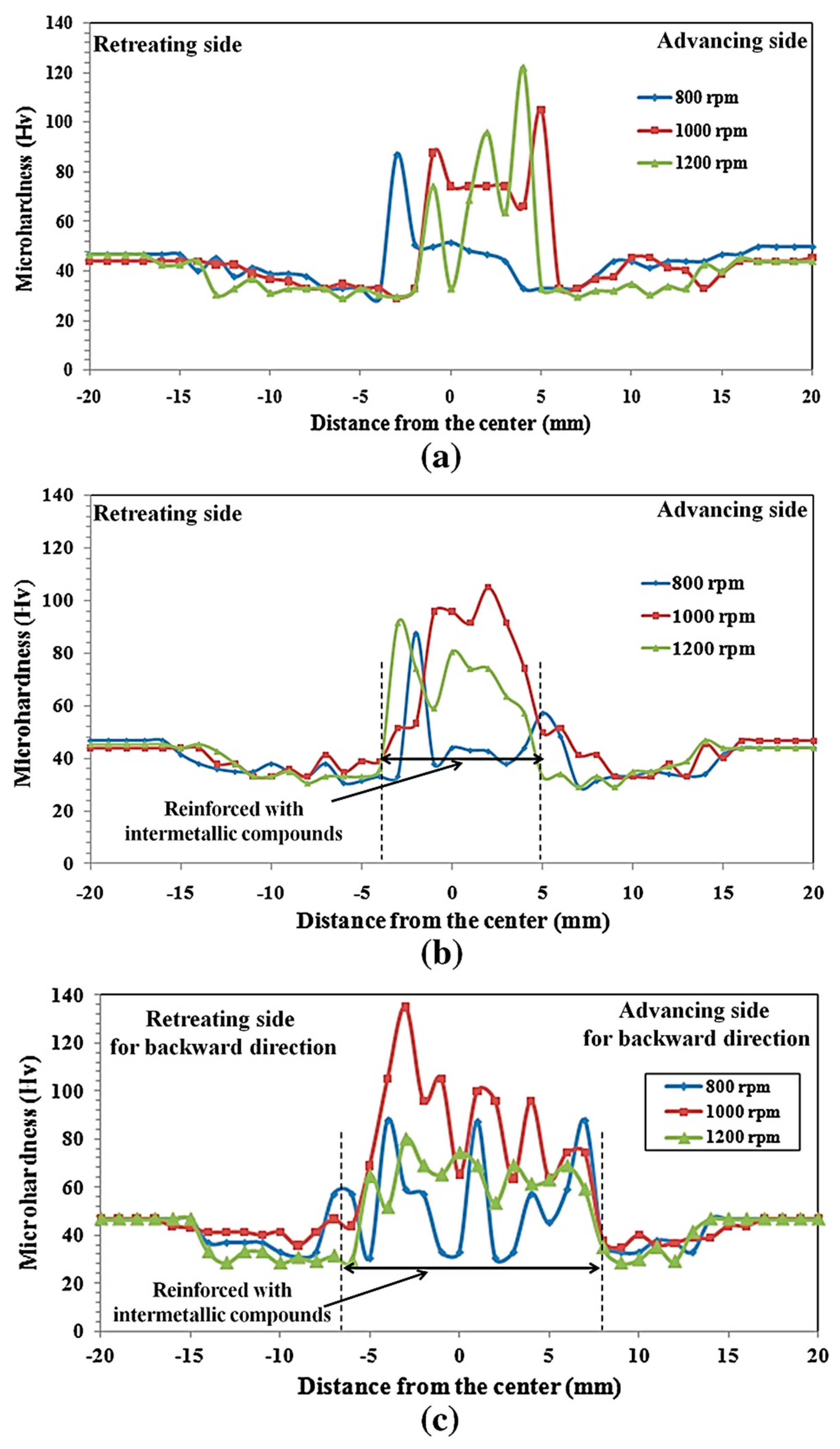
Abnar et al. [56] investigated the effect of incorporating Cu powder on the microstructure and mechanical properties of FSWed joints of AA3003-H18. As observed in Figure 16, the hardness in the cross-section of the joints was uniformly distributed at a rotational speed of 1200 rpm and travel speed of 100 mm/min after Forward-Backward (FB) passes. This was attributed to the Al-Cu in situ intermetallic compounds which were more uniformly dispersed in the Al matrix compared to the low rotational speeds (800 and 1000 rpm) [56]. The increase in the rotational speed and performing the second pass (Forward-Forward or Forward-Backward) led to more interactions between unreacted Cu particles and the aluminum matrix, thus facilitating the formation of the intermetallic compounds [56,169,170,171]. In another attempt, it was shown that embedding premixed Al-Cu powder rather than Cu powder yields a much more uniform hardness profile due to the uniform distribution of Al-Cu intermetallic compounds, such as Al2Cu and AlCu [165].
The incorporation of ceramic nanoparticles is another reinforcement option. The effect of TiO2 nanoparticles on the microhardness profiles of AA5083 FSWed joints showed that the average hardness of the stir zone increased as the number of passes increased. This was due to a decrease in the grain size and a better distribution of the TiO2 nanoparticles in the AA5083 microstructure. The best result for hardness was reported for four pass samples, which were increased by approximately 121 HV compared to the parent metal [163]. In a similar approach, Srivastava et al. [164] studied the effect of Nano-sized SiC particles during the FSW of AA5059-O. They indicated an increase of ~55% in microhardness values in the stir zone relative to the base metal. As the number of FSW passes increased, the heterogeneity of the microhardness profile decreased, and its value increased in the stir zone. Having multiple FSW passes minimized the agglomeration of SiC particles and led to the uniform dispersion of SiC particles [164].
The FSW of AA5083-H111 and AA6082-T6 was also evaluated with TiC nanoparticles. It was demonstrated that the microhardness of the stir zone increased (~18%) after three welding passes due to the TiC nanoparticle reinforcement compared to the hardness of the stir zone of the unreinforced specimen [162].
The strategy of using reinforcement particles in FSW of strain-hardened Al alloys to achieve an increased and uniform hardness with less fluctuation is practical only for the stir zone if the revolutionary pitch (ratio of traverse speed to rotational speed) is kept as low as possible and the multi-pass FSW is used. Although the lower revolutionary pitch and the multi-pass improve the hardness of the stir zone, these circumstances adversely affect the hardness of HAZ due to excessive heat input and annealing. As observed in Figure 16, even though two FSW passes (FB) and a higher rotational speed (1200 rpm) uniformly distribute hardness along the stir zone, the HAZ hardness has the lowest value. For such alloys, the optimum result is achieved by considering the HAZ cooling system, such as water spray, copper backing, or underwater FSW, which are discussed in the following sections.
4.2. Effect of Reinforcement Particles on the Tensile Strength
Mirjavadi et al. [163] reported that the incorporation of TiO2 nanoparticles into AA5083 FSWed joints led to an increase in results of transverse tensile strength relative to samples without TiO2 nanoparticles. They observed that the tensile strength was improved by completing up to four passes of the FSW. Grain refinement, generation of dislocations by thermal mismatch, and work hardening caused by the strain differences were all identified as mechanisms that strengthened the Al matrix containing TiO2 reinforcing particles [163]. According to the study conducted by Khodabakhsh et al. [172], solid-state chemical reactions between TiO2 nanoparticles and the Al-Mg (AA5052) matrix led to in situ formations of Al3Ti and MgO nanoparticles. Accordingly, it is expected that, in addition to TiO2 nanoparticles, other compounds (Al3Ti and MgO) affect the mechanical properties of AA5083 FSWed joints. In another study, it was reported that the embedding of SiC nanoparticles during the FSW of AA5059 led to a higher ultimate tensile strength (342 MPa) value compared to the base metal (321 MPa). Based on this work, multiple FSW passes had a significant impact on enhancing the dispersion of SiC particles and UTS [164].
Furthermore, Hassanifard et al. [167] performed FSW on AA1060-H16 by inserting thin Cu foil with a thickness of 100 and 200 µm between two sheets. Based on their report, the transverse tensile strength was increased by inserting both 100 and 200 µm Cu foil compared to an as-welded sample (without Cu foil). It was observed that copper foil with a thickness of 100 µm resulted in higher tensile strength (101 MPa) than 200 µm thickness (88 MPa). The thicker copper foil caused the excessive formation of the brittle intermetallic compound in the stir zone [167]. The positive effect of TiC nanoparticles on the transverse tensile strength of dissimilar FSW between AA5083-H111 and AA6082-T6 was also suggested [162].
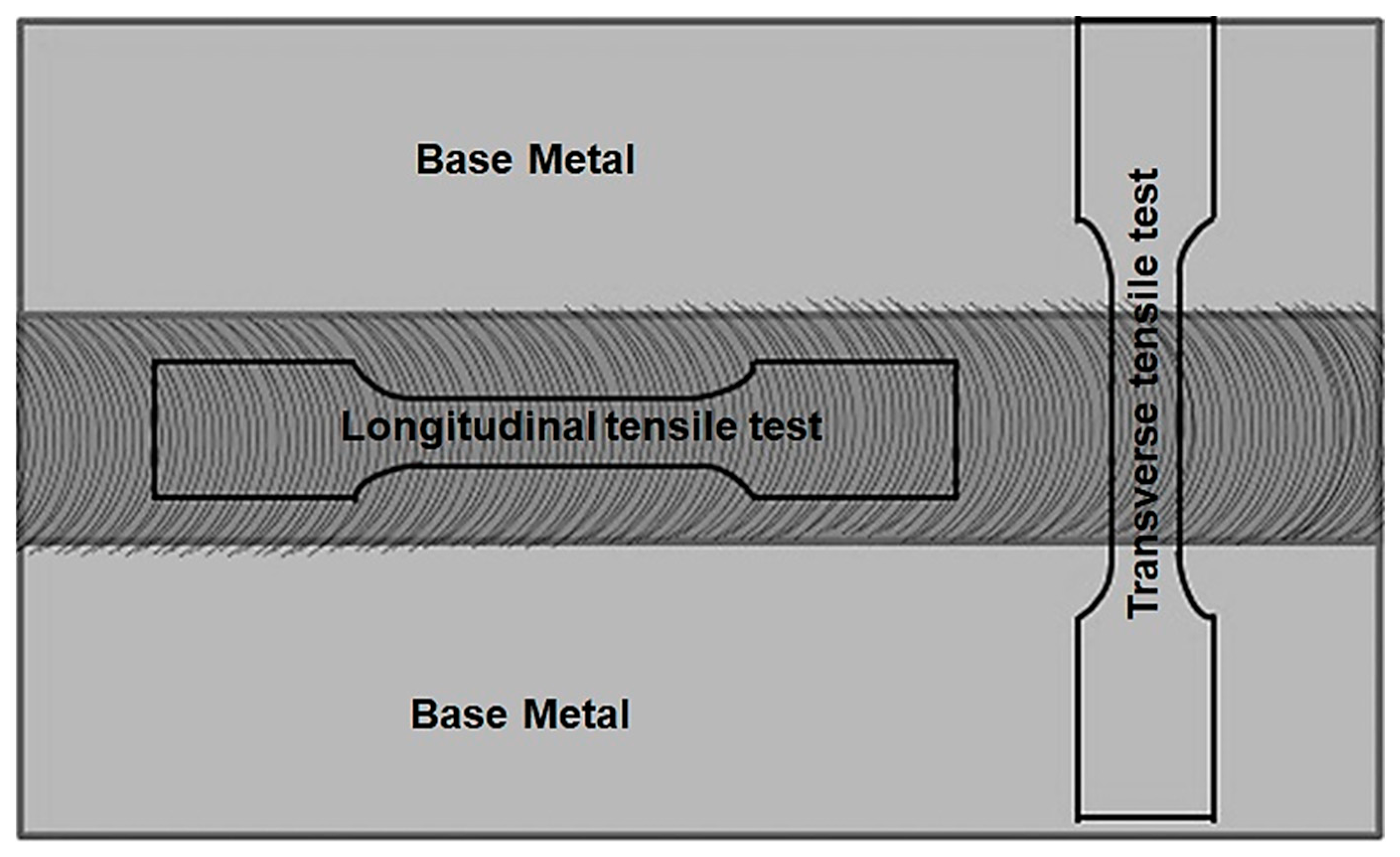
Nevertheless, some studies provided conflicting discussions regarding the transverse tensile strength of reinforced FSWed joints. From their perspective, incorporating reinforcement particles in the FSW of work-hardened Al alloys can only improve the longitudinal tensile strength and does not affect the transverse tensile properties [165]. As observed in Figure 17, the tensile test can be performed in two directions for welded joints: longitudinally (along the weld metal) or transversely (perpendicular to the welding line). In the longitudinal tensile test, the strength only depends on the weld metal properties because the entire test samples are machined from the reinforced stir zone. In other words, the longitudinal tensile test samples are metal matrix composites reinforced by in situ intermetallic compounds or ceramic particles. On the other hand, in the transverse tensile test, the strength depends on the weakest area, which is mostly HAZ in work-hardened aluminum alloys [165,173,174]. According to this view, the proper uniformity of reinforcement particles caused by effective welding parameters (high rotational speeds, low transverse speeds, and multi-pass FSW) only affects the longitudinal tensile strength. The transverse tensile strength is often affected by the mechanical properties of other zones, especially HAZ where reinforcement particles are not embedded. Consequently, increasing the transverse tensile strength depends on strengthening both the stir zone and HAZ in the FSW of H-temper non-heat-treatable Al alloys. As formerly mentioned, the strength of the heat-affected zone (HAZ), as the weakest area, can be controlled by applying an appropriate cooling system, such as water spray, Cu backing, or underwater FSW.
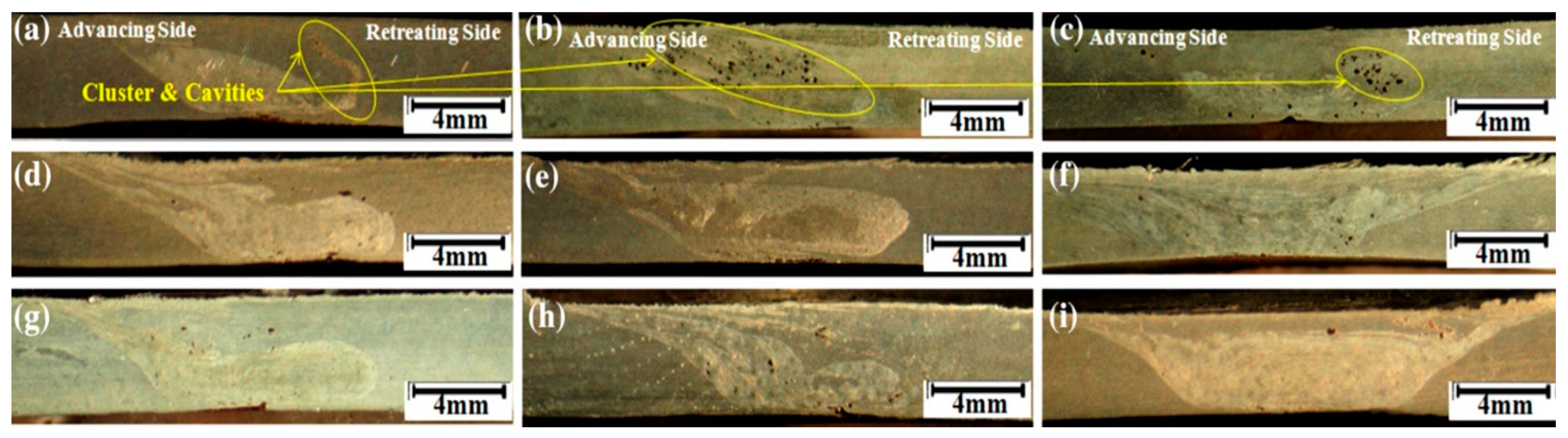
The unfavorable effects of particle clustering and agglomeration on the tensile properties of Al FSWed joints have been frequently reported for the technique of embedding reinforcement particles [56,162,163,168]. To make this approach more effective for tensile strength, the agglomeration must be crushed during FSW. Figure 18 shows the cross-sections of the FSWed joints of AA3003-H18 obtained after adding the copper powder to the gap with two base plates. When the rotational speed was low (800 rpm), large clusters and cavities were formed in the joints due to a lack of sufficient plastic flow and materials mixing, as shown in Figure 18a–c. This defect not only adversely affected the tensile properties, but also shifted the fracture location of the tensile specimen into the stir zone. As shown in Figure 18i, increasing the rotational speed up to 1200 rpm and using two FB passes resulted in a uniform distribution of reinforcement particles in situ Al-Cu intermetallic compounds) without particle agglomeration, achieving higher tensile properties [56].
Additionally, the powder mixture used for FSW of AA3003-H18 had an impressive effect on the tensile properties of welded joints. Figure 19 shows the effect of using pure Cu and premixed Al-Cu at various rotational speeds on the microstructure of FSWed joints. As observed in Figure 19d–f, using premixed Al-Cu provided a more uniform distribution of Cu and in situ Al-Cu intermetallic compounds throughout the stir zone at various rotational speeds. On the other hand, the use of pure Cu powder led to the formation of adverse Cu clusters in the stir zone due to cold welding and mechanical interlocking of particles that were more noticeable at low rotational speeds [Figure 19a–c] [165].
To improve the mechanical properties of H-temper Al alloys with the reinforcement particles strategy, particle agglomeration must be removed as much as possible by utilizing techniques, such as applying multi-pass FSW, decreasing revolutionary pitch, and using mixed powder.
5. Development of Underwater Friction Stir Welding (UFSW)
Many researchers attempted to solve the softening problem in the FSW joint of the work-hardened Al alloys by decreasing the rotational speed and/or increasing the traverse speed. Although this approach reduces the heat input, defects are easily formed at very low rotational speeds or high traverse speeds. Thus, additional cooling is an effective way to reduce heat input during FSW due to the limitation of change in these parameters. [110,175,176,177].
It is well documented that water cooling is a successful technique for improving the quality of the non-heat-treatable Al alloy FSWed joints. Underwater friction stir welding (UFSW) or submerged friction stir welding (SFSW) greatly reduces and controls the temperature and the heat input in the weld area and subsequently enhances the tensile properties, hardness, and fatigue strength of the FSWed joints [48,58,110,178,179,180,181]. Although water cooling is the most efficient and low-cost method that has attracted more attention, other cooling mediums, such as compressed air, liquid nitrogen, water spray, and dry ice, have also been used to reduce the heat input of the FSW process [175,180,182,183]. An overview of the water-cooling effects on the mechanical properties of FSWed joints of non-heat-treatable Al alloys is presented in subsequent sections.
5.1. Effect of UFSW on the Hardness
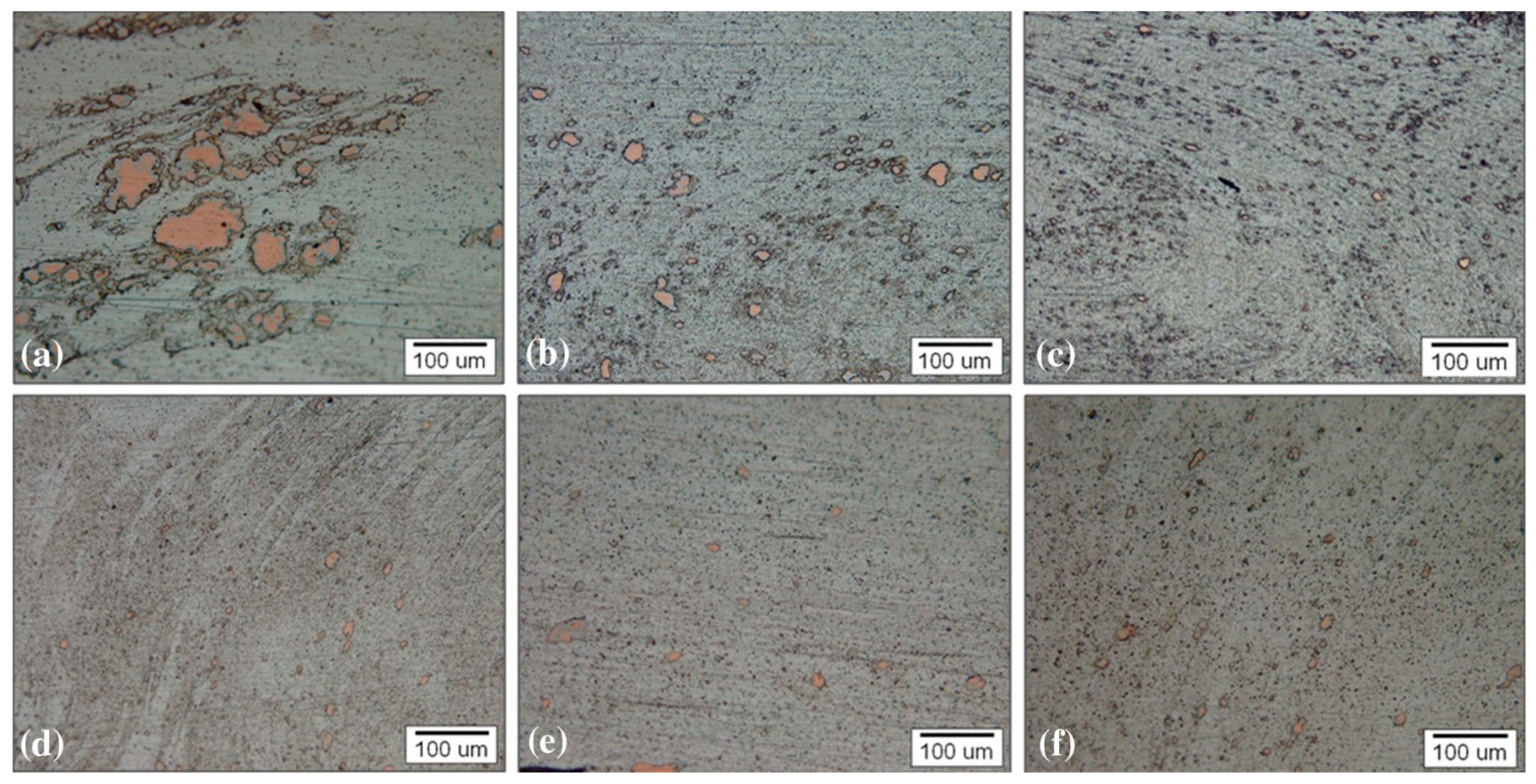
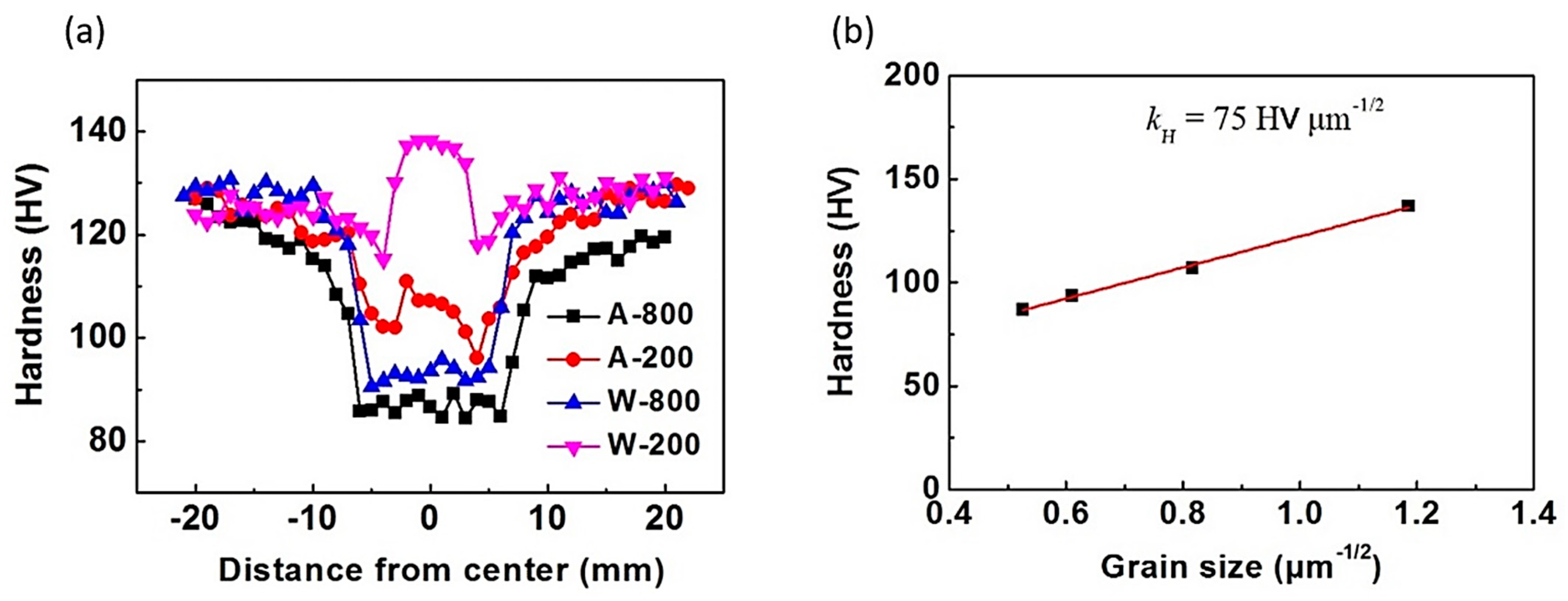
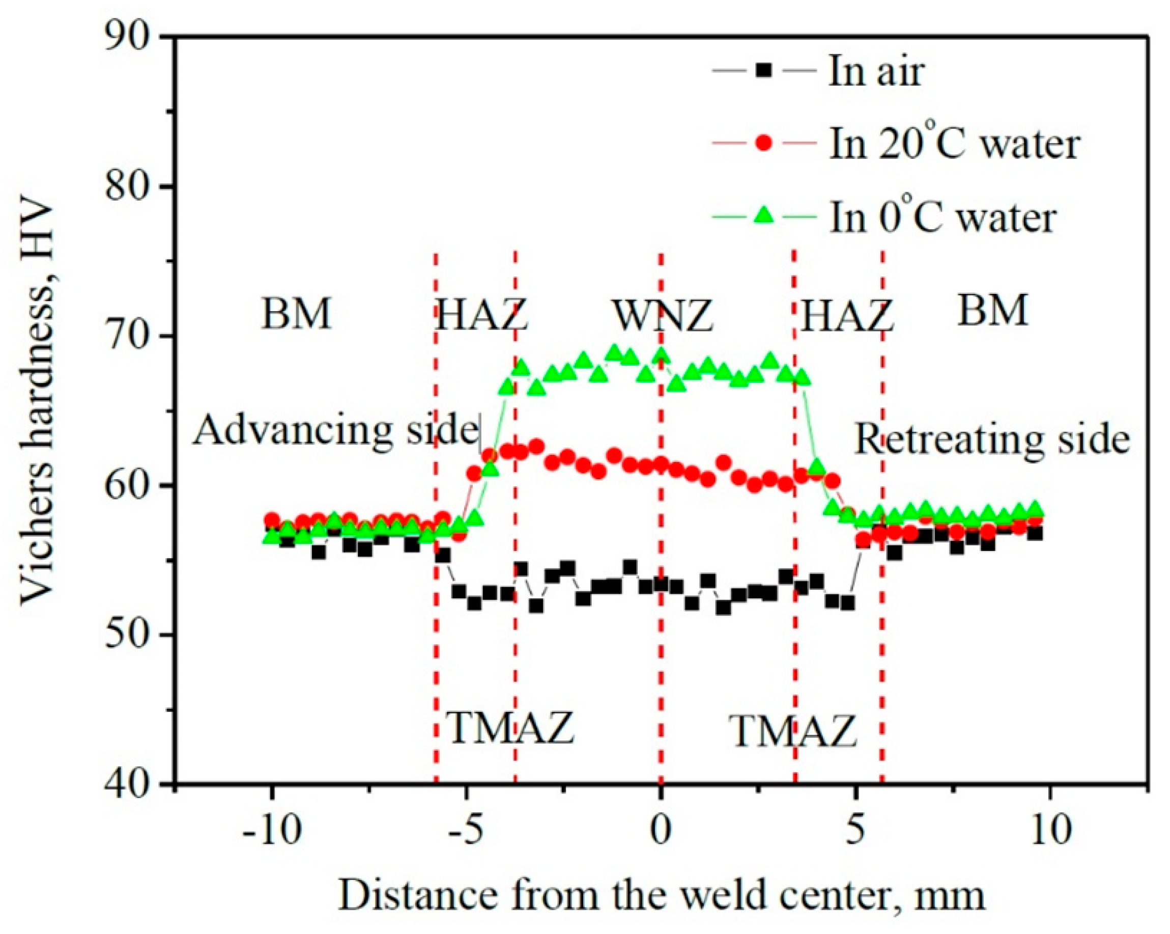
The UFSW of non-heat-treatable Al alloy has been explored to overcome the problem of losing hardness in different microstructural zones. It has been observed that, by applying water cooling, the FSW AA5083-H19 joints lead to the narrowing of the lowest hardness zone (LHZ) and increasing the average hardness of the weld area, especially the stir zone or NZ [175]. Figure 20a shows the microhardness profiles of defect-free welds at 800 and 200 rpm with (W) and without (A) using water cooling in AA5083-H19 FSWed joints. As shown in Figure 20a, the width of LHZ reduces to approximately 10 mm, and the lowest hardness value increases to nearly 90 HV for W-800 compared to A-800. In addition, the higher hardness value (~137 HV) is achieved under rapid water cooling at a very low rotation rate of 200 rpm (W-200) in the stir zone which is slightly higher than the base metal. It is due to the much-refined grain size and higher dislocation densities in the stir zone [175]. Figure 20b shows the correlation between the average grain size and the hardness value in the stir zone of various samples. The hardness value (HV) increases with decreasing grain size. According to the results, the average grain size was decreased from 1.8 µm to 0.8 µm using water cooling at a rotational speed of 200 rpm in AA5083-H19 FSWed joints [110,175]. According to Figure 20a (W-200), there was no significant softening effect in the HAZ which was attributed to the considerably decreased peak temperature and duration time at the high temperatures. In other attempts, similar behaviors were reported for hardness and grain size. For instance, Tan et al. [59] studied the microstructure and mechanical properties of AA3003 FSWed joints by using 20 °C and 0 °C water. Compared with conventional methods (FSW in the air), using a water-cooling medium and decreasing the water temperature from 20 °C and 0 °C increased the average hardness value in the stir zone of as-received AA3003, as depicted in Figure 21. They also correlated the increase in hardness with the decrease in grain size of the AA3003 FSWed joints microstructure. Additionally, the width of the HAZ and hardening zone decreased with decreasing the welding ambient temperature from 20 °C and 0 °C [59].
As a result, applying UFSW, which concentrates the heat under the welding tool, not only increases the hardness of the weld area, but also decreases the width of HAZ and SZ in non-heat-treatable Al alloys. The high cooling rate of UFSW does not provide adequate time for the grains to grow in the weld zone [184,185].
5.2. Effect of UFSW on Tensile Strength
Several studies have shown that cooling media significantly improve the tensile properties of FSW joints so that underwater samples of FSW have strength very similar to base metal samples [41,58,180,186].
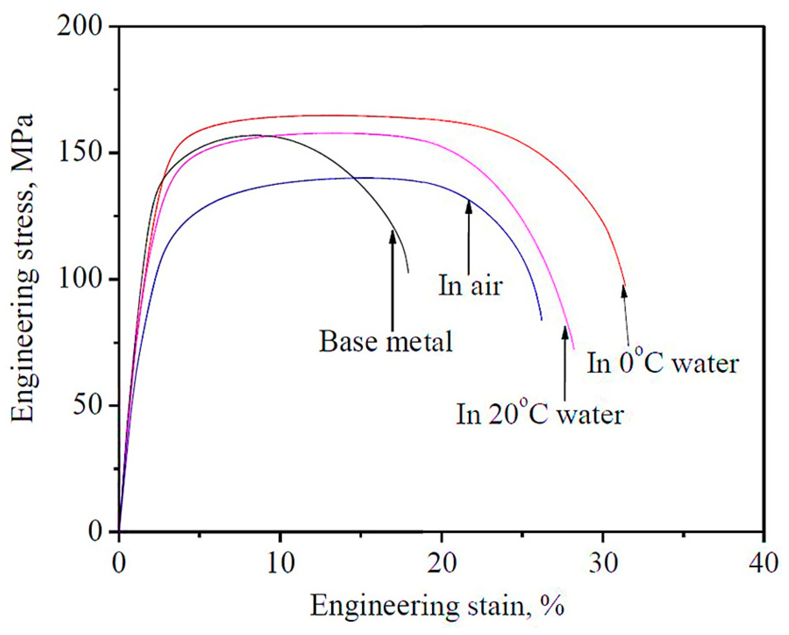
Heirani et al. [184] studied the microstructure and mechanical behaviors of UFSW on AA5083. They revealed that the water cooling showed an increase in the tensile strength due to the increased hardness in the SZ resulting from an ultrafine-grain structure. The strength improvement is attributed to high resistance to uniform plastic deformation during the experiment of defect-free FSWed joints [184]. Additionally, Wang et al. [175] achieved defect-free FSWed joints of AA5083-H19 at 800 and 200 rpm with and without applying water cooling. In their work, UFSW at a rotational speed of 200 rpm leads to high tensile strength (403 MPa) with nearly equal strength to the BM (425 MPa) due to the significantly reduced softening, while FSW at the same rotational speed achieves a tensile strength of 344 MPa [175]. Moreover, as observed in the engineering stress-strain curves of Figure 22, water flow and a decrease in temperature from 20 °C to 0 °C increased the tensile properties of FSWed joints for hot bands of AA3003. The increase in tensile properties of strain-hardened Al alloys was mainly caused by grain refinement. Grain boundaries usually act as a strong barrier to the transmission of slip from one crystal to its neighbor during deformation, leading to an increase in the tensile strength and yield strength of the weld zone [59].
Despite the significant effect of UFSW on increasing the tensile strength of joints, researchers were challenged when attempting to apply it. The studies on UFSW of work-hardened Al alloys revealed that higher rotational speed is required to produce high-quality and defect-free welds compared to normal FSW. Kishta et al. [185] worked on underwater FSW of AA5083 at various rotational speeds (1000, 1500, and 1700 rpm) and traverse speeds of 75 mm/min. They observed that the UFSW joint at 1000 rpm showed lower tensile strength than that of the normal FSW joint. According to their findings, at 1000 r/min, the heat input to the weld was insufficient to soften the metal, producing a defective weld, while during normal FSW (in the air), a rotational speed of 1000 r/min applied enough heat to soften and properly stir the material (Figure 23). Under this condition, the UFSW sample is subjected to a very low peak temperature and a higher cooling rate relative to the FSW sample. UFSW requires a rotational speed of 1700 r/min to produce a good-quality weld [185]. Similar observations were reported by Shanavas et al. [187] for UFSW of AA5052 at tool rotational speeds of 500, 600, 700, 800, and 900 rpm. They demonstrated that the tensile strength of the UFSW joint was higher than that of normal FSWed joints, except at 500 rpm. At a rotational speed of 500 rpm, the heat input is not enough to achieve defect-free joints, resulting in reduced tensile strength compared to conventional FSW [187].
5.3. Effect of UFSW on Fatigue Life
In most FSW structures, such as aerospace, marine, and transport vehicles, the different parts are highly subjected to cyclic stress and strains resulting in fatigue and cyclic deformation [58].
There are several factors affecting the fatigue behavior of the FSWed joints such as welding parameters (heat input), welding defects, surface roughness, and residual stresses. In general, for defect-free joints, the fatigue cracks are initiated by the local deformation in the softened area, derived from the annealing effect during the FSW process [44,110,111]. Therefore, it is essential to improve the hardness and strength of the softened zone of FSWed joints to achieve high fatigue strength. Using water cooling is a novel and high-efficiency approach to achieving high fatigue strength in FSWed joints of non-heat-treatable Al alloys [59,110,180]. Moreover, the UFSW results in lower heat input, leading to lower residual stresses and less distortion which are usually favorable conditions for fatigue performance [25,33,60,184]. Wang et al. [110] indicated that applying water cooling at a rotational speed of 200 rpm led to an FSW joint with fatigue strength equal to the base metal in AA5083-H19 rolled plates. Based on their work, the fatigue limit increased from 180 MPa to 240 MPa using water cooling at a rotational speed of 200 rpm in AA5083-H19 FSWed joints [110].
6. Other Approaches
Other supplementary approaches to improve the quality of FSWed joints of work-hardened Al alloys include surface modification, Bobbin tool FSW, Cu backing, and double-sided friction stir welding (DS-FSW), which are briefly discussed below.
6.1. Surface Modification
To improve fatigue life, surface treatments are offered to increase the fatigue properties of non-heat-treatable FSWed joints. Mechanical machining of the surface marks is suggested to achieve a consistent and smooth weld surface [44,61,62]. James et al. [96] reported that for the as-welded specimens of AA5383-H321, the crack initiation was often related to surface tool rotation marks, but for the case of surface polished specimens, crack initiation reflected either slip band cracking or small internal voids during the test [96].
Furthermore, some techniques were introduced as mechanical surface modifications that can reduce the residual stress levels or apply compressive stresses that offer powerful enhancement of fatigue properties of FSWed joints [2,188,189]. Soyama et al. [188] reported the beneficial effect of cavitation peening on the fatigue properties in the FSW of AA5754 by introducing compressive residual stress into the FSWed part.
6.2. Bobbin Tool FSW
In conventional tool friction stir welding (CT-FSW), only one shoulder and one pin are used. In addition, a backing plate, which is often steel, supports the workpiece to prevent physical deformation or distortion of the welds. One of the disadvantages of CT-FSW is insufficient tool penetration or lack of penetration (Figure 24). This root defect is caused by inadequate tool stirring at the root region of the joint, which adversely affects the weld quality. A new technique has been developed to solve these problems, which is a variant of FSW called the Bobbin tool FSW (BT-FSW) [26,27,63,80]. The bobbin tool is equipped with an additional shoulder that is fastened to the tip of the pin and is known as the lower shoulder (Figure 25) [190,191]. This technique allows an effective stirring action and enough movement around the pin from the top to the bottom of the workpiece along the weld joint line [27,192]. Symmetric features of BT-FSW in the joint’s thickness direction are considered one of its main advantages compared to the CT-FSW in terms of frictional heat distribution, material flow, and uniformity of micro and macrostructure [190,191,192,193].
Although most of the studies on the BT-FSW are related to heat-treatable alloys, it is expected that the implementation of this approach on non-heat-treatable Al alloys makes it possible to obtain superior mechanical properties in welded joints.
6.3. Cu Backing
As previously discussed, further cooling is a useful strategy for reducing the heat input as well as the softening effect during FSW of work-hardened Al alloys. A Cu backing plate can be used to accelerate heat flow, leading to faster cooling of the FSW [64,194]. Shukla et al. [194] studied the grain size dependence of the fatigue properties of FSW of AA5024 with and without using Cu backing. According to their report, applying Cu backing resulted in the smallest grain size, superior tensile properties, and longer fatigue life in comparison with the samples welded without Cu backing [194]. However, some studies did not recommend Cu backing. According to their argument, materials with high thermal conductivity are not appropriate as a backing because they make it easier for a void defect to form during FSW; as Cu causes an excessive heat output at the bottom of workpieces, it is considered inappropriate. To compensate for this effect, increasing the rotational speed is required [65,195].
6.4. Double-Sided Friction Stir Welding (DS-FSW)
There is a risk of distortion and stress concentration in the FSW joints due to the asymmetric and non-uniform mechanical properties in the joints. This non-uniformity in the welding lines is mostly revealed by the asymmetry of microhardness. Several investigations on FSWed joints of non-heat-treatable Al alloys, such as 1050-H24 [31,196], 1100-H14 [107], 3003-H8 [38], and 5083 [139,146], 5086 [148], suggested that a minimum hardness is often located in the advancing side.
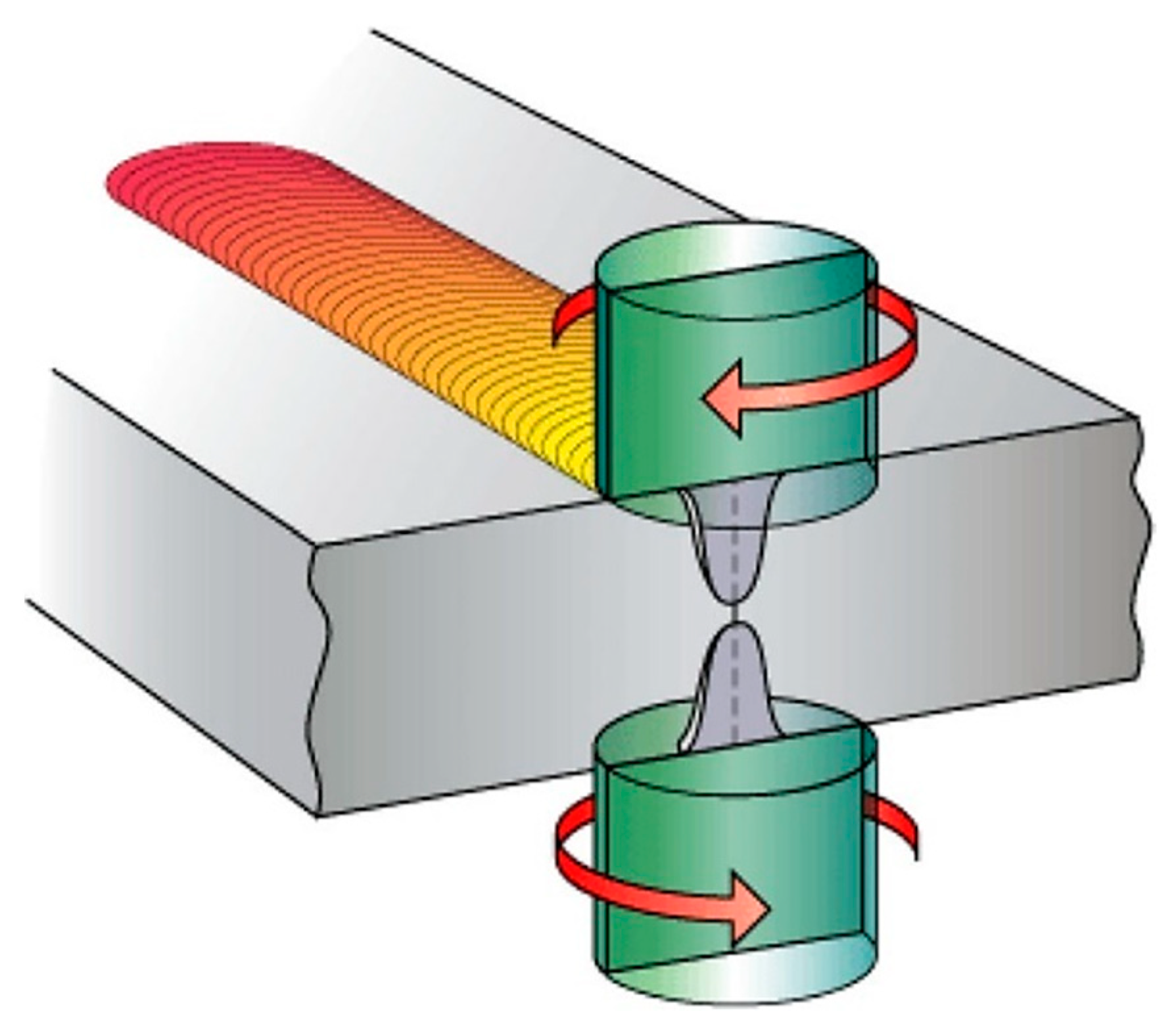
Double-sided friction stir welding (DS-FSW) of the non-heat-treatable Al alloy has been proposed to achieve a defect-free joint with a symmetric microstructure and desirable tensile properties, especially for thicker plates, as shown in Figure 26 [10,15,197,198]. DS-FSW has little effect on increasing the average hardness of the weld area compared to one-sided FSW, but it causes symmetry of the hardness on both the advancing side (AS) and retreating side (RS) in FSW of Al alloys. In addition, double-sided welds with the same direction (both passes start from the same end) provide higher strength than one-sided welds [66,107,161].
7. Future Outlooks
To determine the joint efficiency, i.e., the ratio between the tensile strength of the welded joint and the unwelded base metal, the transverse tensile strength is considered. Therefore, to reach the optimal mechanical properties with the highest joint efficiency in FSWed joints of work-hardened non-heat-treatable Al alloys, it is critical to implement approaches that reinforce all weld zones (SZ, HAZ, and TMAZ), not just one area. Currently, available works have mostly focused on a specific approach to increasing joint efficiency; for instance, changing the rotational/traverse speeds or tool design. More research is needed to combine the various methods used to strengthen the weld zone. For example, one technique is used to augment the mechanical properties of HAZ/TMAZ and another is applied to the reinforcement of the stir zone with metal or ceramic particles. Some of these combinations can be “UFSW/Water spray + Optimal rotational and traverse speeds”, “UFSW/Water spray + reinforcement particles”, “DS-FSW + Reinforcement particles”, “BT-FSW+ UFSW/Water spray”, etc.
8. Summary
On one hand, heat input is responsible for reducing the mechanical properties of work-hardened non-heat-treatable Al alloys in FSWed joints due to the severe softening, but on the other hand, the heat input is essential for making a defect-free joint. Accordingly, there are challenges associated with the use of these alloys. This comprehensive review attempts to present the various strategies for improving the quality of FSW joints in these alloys. The main conclusions of this study are as follows:
- Increasing the ratio of traverse to rotational speed (revolutionary pitch) can lead to three consequences: less softening effect, more defect formation (tunneling, hooking, and kissing bonds), and less distortion.
- Low softening caused by less heat input leads to an increase in the mechanical properties of the defect-free FSWed joint. However, insufficient heat input increases the risk of defect formation. Furthermore, the distortion and unfavorable residual stress, as factors affecting fatigue performance, are limited by low heat input in FSWed joints of non-heat-treatable Al alloys. Therefore, to achieve a high joint quality with minimum softening, defects, and distortion, the rotational and traverse speeds must be optimized.
- Proper tool design allows for the creation of defect-free joints in the FSW of non-heat-treatable Al alloys. Threaded pins (both taper and cylindrical shapes) are recommended for lower tool rotational speed. Due to severe turbulence in the material flow, using threaded tools at higher rotational speeds compromises the quality of the weld. Furthermore, unthreaded tapered (conical) pins offer better weld quality than straight cylindrical ones. The modified 3-flute pin is an effective design which enhances joint efficiency. In addition, the square pin design produces higher quality FSWed joints relative to other polyhedral shapes.
- The tool tilt angle, depending on the pin design, is responsible for the corrugated friction surface defects that often lead to fatigue cracks. Threaded pins demand a higher tool tilt angle in comparison with unthreaded pins. Additionally, a high tilt angle leads to negative shoulder plunge depth which results in weld thinning and excessive flash in FSWed joints. Too shallow of a plunge depth creates insufficient plasticized materials, leading to inner channel defects or surface grooves. Too deep of a plunge depth establishes the local thinning and improper flash, resulting in stress concentration and low fatigue life.
- Embedding reinforcement particles into the Al matrix during FSW is a progressive method to increase the hardness and longitudinal tensile test of the stir zone in work-hardened Al alloys. These particles can be ceramic, such as TiC and TiO2, or in situ compounds made with metal powder (such as Cu). The lower revolutionary pitch and the multi-pass FSW prevent the agglomeration of powder and make a uniform distribution of reinforcement particles with further abrasion and crushing in the microstructure. Using reinforcement particles would be effective if cooling of HAZ is in progress. Forward-Backward (FB) multi-pass is not only an effective approach to obtain uniform and symmetrical dispersion of reinforcement particles with minimum agglomeration, it also facilitates the formation of the intermetallic compounds in the stir zone when the metal powder is used.
- Water cooling during FSW (underwater FSW) is a successful method to increase the hardness and strength of the non-heat-treatable Al alloy joints due to a decrease in the average grain size in the different weld areas. The UFSW requires a higher rotational speed to produce high-quality and defect-free welds compared to the conventional process. Because the fatigue cracks may be initiated by the local deformation in the softened area, applying water cooling would be a high-efficiency approach to achieving high fatigue strength in a FSWed joints. Moreover, joints with lower residual stresses and less distortion are a notable benefit of UFSW compared to normal FSW.
- Other measures are implemented to achieve the high joint quality in FSW of work-hardened Al alloys. Polishing, machining, and peening improve fatigue performance by smoothing the surface and introducing compressive residual stress. In addition, the defects of the conventional FSW process (e.g., insufficient tool penetration and other root flaws) can be resolved by using the bobbin tool. Furthermore, asymmetric properties of FSWed joints in thick plates are minimized by using a double-sided FSW process, decreasing the distortion and stress concentration of the welded joint. The utilization of a high thermal conductivity metal, such as Cu, as a backing plate is another method of effective cooling to control excessive heat input and produce a softening effect.
Author Contributions
Conceptualization, methodology, review, and editing, M.J. and B.A.; Supervision, M.J.; Writing, original draft preparation, B.A.; Investigation, resources, S.G. All authors have read and agreed to the published version of the manuscript.
Funding
This research received no external funding.
Institutional Review Board Statement
Not applicable.
Informed Consent Statement
Not applicable.
Data Availability Statement
Not applicable.
Conflicts of Interest
The authors declare no conflict of interest.
References
- Mishra, R.S.; Ma, Z. Friction stir welding and processing. Mater. Sci. Eng. R Rep. 2005, 50, 1–78. [Google Scholar] [CrossRef]
- Threadgill, P.; Leonard, A.; Shercliff, H. Friction stir welding of aluminium alloys. Int. Mater. Rev. 2009, 54, 49–93. [Google Scholar] [CrossRef]
- Ma, Z.; Feng, A.; Chen, D.; Shen, J. Recent advances in friction stir welding/processing of aluminum alloys: Microstructural evolution and mechanical properties. Crit. Rev. Solid State Mater. Sci. 2018, 43, 269–333. [Google Scholar] [CrossRef]
- Akinlabi, E.T.; Mahamood, R.M. Solid-State Welding: Friction and Friction Stir Welding Processes; Springer: Cham, Switzerland, 2020. [Google Scholar]
- AWS A3.0M/A3.0; Standard Welding Terms and Definitions; Including Terms for Adhesive Bonding, Brazing, Soldering, Thermal Cutting, and Thermal Spraying, 13th ed.; American Welding Society: Miami, FL, USA, 2020; p. 190.
- Ke, W.; Oliveira, J.; Ao, S.; Teshome, F.; Chen, L.; Peng, B.; Zeng, Z. Thermal process and material flow during dissimilar double-sided friction stir spot welding of AZ31/ZK60 magnesium alloys. J. Mater. Res. Technol. 2022, 17, 1942–1954. [Google Scholar] [CrossRef]
- Oliveira, J.P.; Duarte, J.; Inácio, P.; Schell, N.; Miranda, R.; Santos, T.G. Production of Al/NiTi composites by friction stir welding assisted by electrical current. Mater. Des. 2017, 113, 311–318. [Google Scholar] [CrossRef] [Green Version]
- Costa, A.M.S.; Oliveira, J.; Pereira, V.; Nunes, C.A.; Ramirez, A.J.; Tschiptschin, A.P. Ni-based Mar-M247 superalloy as a friction stir processing tool. J. Mater. Process. Technol. 2018, 262, 605–614. [Google Scholar] [CrossRef]
- Aliha, M.; Kalantari, M.; Ghoreishi, S.; Torabi, A.; Etesam, S. Mixed mode I/II crack growth investigation for bi-metal FSW aluminum alloy AA7075-T6/pure copper joints. Theor. Appl. Fract. Mech. 2019, 103, 102243. [Google Scholar] [CrossRef]
- Cam, G.; Mistikoglu, S. Recent developments in friction stir welding of Al-alloys. J. Mater. Eng. Perform. 2014, 23, 1936–1953. [Google Scholar] [CrossRef]
- Mathers, G. The Welding of Aluminium and Its Alloys; Woodhead Publishing: Abington, UK, 2002. [Google Scholar]
- Rai, R.; De, A.; Bhadeshia, H.; DebRoy, T. Friction stir welding tools. Sci. Technol. Weld. Join. 2011, 16, 325–342. [Google Scholar] [CrossRef]
- Eren, B.; Guvenc, M.A.; Mistikoglu, S. Artificial intelligence applications for friction stir welding: A review. Met. Mater. Int. 2021, 27, 193–219. [Google Scholar] [CrossRef]
- Xu, W.; Wu, X.; Ma, J.; Lu, H.; Luo, Y. Abnormal fracture of 7085 high strength aluminum alloy thick plate joint via friction stir welding. J. Mater. Res. Technol. 2019, 8, 6029–6040. [Google Scholar] [CrossRef]
- Taban, E.; Kaluc, E. Microstructural and mechanical properties of double-sided MIG, TIG and friction stir welded 5083-H321 aluminium alloy. Kov. Mater. 2006, 44, 25. [Google Scholar]
- Paik, J.K. Mechanical properties of friction stir welded aluminum alloys 5083 and 5383. Int. J. Nav. Archit. Ocean. Eng. 2009, 1, 39–49. [Google Scholar] [CrossRef] [Green Version]
- Davis, J.R. Aluminum and Aluminum Alloys; ASM International: Novelty, OH, USA, 1993. [Google Scholar]
- Mondolfo, L.F. Aluminum Alloys: Structure and Properties; Butterworth-Heinemann: London, UK, 2013. [Google Scholar]
- Kaufman, J.G. Introduction to Aluminum Alloys and Tempers; ASM Handbook: Novelty, OH, USA, 2000. [Google Scholar]
- Cayless, R. Alloy and Temper Designation Systems for Aluminum and Aluminum Alloys; ASM International: Novelty, OH, USA, 2013. [Google Scholar]
- Sahlot, P.; Jha, K.; Dey, G.; Arora, A. Quantitative wear analysis of H13 steel tool during friction stir welding of Cu-0.8% Cr-0.1% Zr alloy. Wear 2017, 378, 82–89. [Google Scholar] [CrossRef]
- Djurdjanovic, M.; Mijajlovic, M.; Milcic, D.; Stamenkovic, D. Heat generation during friction stir welding process. Tribol. Ind. 2009, 31, 8. [Google Scholar]
- Schmidt, H.; Hattel, J.; Wert, J. An analytical model for the heat generation in friction stir welding. Model. Simul. Mater. Sci. Eng. 2003, 12, 143. [Google Scholar] [CrossRef]
- Fujii, H.L.H.; Nogi, K. Tensile Properties of A Friction Stir Welded Thin-Sheet of 1050-H24 Aluminum Alloy. Charact. Control. Interfaces High Qual. Adv. Mater. 2012, 146, 129–136. [Google Scholar]
- Peel, M.; Steuwer, A.; Preuss, M.; Withers, P. Microstructure, mechanical properties and residual stresses as a function of welding speed in aluminium AA5083 friction stir welds. Acta Mater. 2003, 51, 4791–4801. [Google Scholar] [CrossRef]
- Meng, X.; Huang, Y.; Cao, J.; Shen, J.; dos Santos, J.F. Recent progress on control strategies for inherent issues in friction stir welding. Prog. Mater. Sci. 2021, 115, 100706. [Google Scholar] [CrossRef]
- Ogunsemi, B.; Abioye, T.; Ogedengbe, T.; Zuhailawati, H. A review of various improvement strategies for joint quality of AA 6061-T6 friction stir weldments. J. Mater. Res. Technol. 2021, 11, 1061–1089. [Google Scholar] [CrossRef]
- Laska, A.; Szkodo, M. Manufacturing parameters, materials, and welds properties of butt friction stir welded joints—Overview. Materials 2020, 13, 4940. [Google Scholar] [CrossRef]
- Heidarzadeh, A.; Mironov, S.; Kaibyshev, R.; Çam, G.; Simar, A.; Gerlich, A.; Khodabakhshi, F.; Mostafaei, A.; Field, D.; Robson, J. Friction stir welding/processing of metals and alloys: A comprehensive review on microstructural evolution. Prog. Mater. Sci. 2021, 117, 100752. [Google Scholar] [CrossRef]
- Leng, L.; Zhang, Z.; Duan, Q.; Zhang, P.; Zhang, Z. Improving the fatigue strength of 7075 alloy through aging. Mater. Sci. Eng. A 2018, 738, 24–30. [Google Scholar] [CrossRef]
- Liu, H.; Fujii, H.; Maeda, M.; Nogi, K. Mechanical properties of friction stir welded joints of 1050–H24 aluminium alloy. Sci. Technol. Weld. Join. 2003, 8, 450–454. [Google Scholar] [CrossRef]
- Frigaard, Ø.; Grong, Ø.; Midling, O. A process model for friction stir welding of age hardening aluminum alloys. Metall. Mater. Trans. A 2001, 32, 1189–1200. [Google Scholar] [CrossRef]
- Linton, V.; Ripley, M. Influence of time on residual stresses in friction stir welds in agehardenable 7xxx aluminium alloys. Acta Mater. 2008, 56, 4319–4327. [Google Scholar] [CrossRef]
- Sato, Y.S.; Kokawa, H.; Enomoto, M.; Jogan, S.; Hashimoto, T. Precipitation sequence in friction stir weld of 6063 aluminum during aging. Metall. Mater. Trans. A 1999, 30, 3125–3130. [Google Scholar] [CrossRef]
- Sato, Y.S.; Kokawa, H. Distribution of tensile property and microstructure in friction stir weld of 6063 aluminum. Metall. Mater. Trans. A 2001, 32, 3023–3031. [Google Scholar] [CrossRef]
- Kalemba, I.; Hamilton, C.; Dymek, S. Natural aging in friction stir welded 7136-T76 aluminum alloy. Mater. Des. 2014, 60, 295–301. [Google Scholar] [CrossRef]
- Threadgill, P. Terminology in friction stir welding. Sci. Technol. Weld. Join. 2007, 12, 357–360. [Google Scholar] [CrossRef]
- Abnar, B.; Kazeminezhad, M.; Kokabi, A. Effects of heat input in friction stir welding on microstructure and mechanical properties of AA3003-H18 plates. Trans. Nonferrous Met. Soc. China 2015, 25, 2147–2155. [Google Scholar] [CrossRef]
- Bocchi, S.; D’Urso, G.; Giardini, C. The effect of heat generated on mechanical properties of friction stir welded aluminum alloys. Int. J. Adv. Manuf. Technol. 2021, 112, 1513–1528. [Google Scholar] [CrossRef]
- Amini, S.; Amiri, M.; Barani, A. Investigation of the effect of tool geometry on friction stir welding of 5083-O aluminum alloy. Int. J. Adv. Manuf. Technol. 2015, 76, 255–261. [Google Scholar] [CrossRef]
- Xu, W.; Liu, J.; Chen, D.; Luan, G.; Yao, J. Improvements of strength and ductility in aluminum alloy joints via rapid cooling during friction stir welding. Mater. Sci. Eng. A 2012, 548, 89–98. [Google Scholar] [CrossRef]
- Khorrami, M.S.; Kazeminezhad, M.; Kokabi, A. Thermal stability during annealing of friction stir welded aluminum sheet produced by constrained groove pressing. Mater. Des. 2013, 45, 222–227. [Google Scholar] [CrossRef]
- Kulekci, M.K.; Şik, A.; Kaluç, E. Effects of tool rotation and pin diameter on fatigue properties of friction stir welded lap joints. Int. J. Adv. Manuf. Technol. 2008, 36, 877–882. [Google Scholar] [CrossRef]
- Li, H.; Gao, J.; Li, Q. Fatigue of friction stir welded aluminum alloy joints: A review. Appl. Sci. 2018, 8, 2626. [Google Scholar] [CrossRef] [Green Version]
- Bussu, G.; Irving, P. The role of residual stress and heat affected zone properties on fatigue crack propagation in friction stir welded 2024-T351 aluminium joints. Int. J. Fatigue 2003, 25, 77–88. [Google Scholar] [CrossRef]
- James, M.; Bradley, G.; Lombard, H.; Hattingh, D. The relationship between process mechanisms and crack paths in friction stir welded 5083-H321 and 5383-H321 aluminium alloys. Fatigue Fract. Eng. Mater. Struct. 2005, 28, 245–256. [Google Scholar] [CrossRef]
- Kalemba-Rec, I.; Kopyściański, M.; Miara, D.; Krasnowski, K. Effect of process parameters on mechanical properties of friction stir welded dissimilar 7075-T651 and 5083-H111 aluminum alloys. Int. J. Adv. Manuf. Technol. 2018, 97, 2767–2779. [Google Scholar] [CrossRef] [Green Version]
- Janeczek, A.; Tomków, J.; Fydrych, D. The influence of tool shape and process parameters on the mechanical properties of AW-3004 aluminium alloy friction stir welded joints. Materials 2021, 14, 3244. [Google Scholar] [CrossRef]
- Singh, K.; Singh, G.; Singh, H. Review on friction stir welding of magnesium alloys. J. Magnes. Alloys 2018, 6, 399–416. [Google Scholar] [CrossRef]
- Dialami, N.; Cervera, M.; Chiumenti, M. Effect of the tool tilt angle on the heat generation and the material flow in friction stir welding. Metals 2018, 9, 28. [Google Scholar] [CrossRef] [Green Version]
- Lohwasser, D.; Chen, Z. Friction Stir Welding: From Basics to Applications; Woodhead Publishing: Cornwall, UK, 2009. [Google Scholar]
- Iqbal, M.P.; Vishwakarma, R.K.; Pal, S.K.; Mandal, P. Influence of plunge depth during friction stir welding of aluminum pipes. Proc. Inst. Mech. Eng. Part B J. Eng. Manuf. 2020. [Google Scholar] [CrossRef]
- Rastabi, S.A.; Mosallaee, M. Effects of multipass friction stir processing and Mg addition on the microstructure and tensile properties of Al 1050 alloys. Int. J. Miner. Metall. Mater. 2022, 29, 97–107. [Google Scholar] [CrossRef]
- Arora, H.; Singh, H.; Dhindaw, B. Composite fabrication using friction stir processing—A review. Int. J. Adv. Manuf. Technol. 2012, 61, 1043–1055. [Google Scholar] [CrossRef]
- Sharma, V.; Prakash, U.; Kumar, B.M. Surface composites by friction stir processing: A review. J. Mater. Process. Technol. 2015, 224, 117–134. [Google Scholar] [CrossRef]
- Abnar, B.; Kazeminezhad, M.; Kokabi, A. The effect of Cu powder during friction stir welding on microstructure and mechanical properties of AA3003-H18. Metall. Mater. Trans. A 2014, 45, 3882–3891. [Google Scholar] [CrossRef]
- Huang, G.; Hou, W.; Li, J.; Shen, Y. Development of surface composite based on Al-Cu system by friction stir processing: Evaluation of microstructure, formation mechanism and wear behavior. Surf. Coat. Technol. 2018, 344, 30–42. [Google Scholar] [CrossRef]
- Wahid, M.A.; Siddiquee, A.N. Review on underwater friction stir welding: A variant of friction stir welding with great potential of improving joint properties. Trans. Nonferrous Met. Soc. China 2018, 28, 193–219. [Google Scholar] [CrossRef]
- Tan, Y.; Wang, X.; Ma, M.; Zhang, J.; Liu, W.; Fu, R.; Xiang, S. A study on microstructure and mechanical properties of AA 3003 aluminum alloy joints by underwater friction stir welding. Mater. Charact. 2017, 127, 41–52. [Google Scholar] [CrossRef]
- Lombard, H.; Hattingh, D.; Steuwer, A.; James, M. Effect of process parameters on the residual stresses in AA5083-H321 friction stir welds. Mater. Sci. Eng. A 2009, 501, 119–124. [Google Scholar] [CrossRef]
- Lomolino, S.; Tovo, R.; Dos Santos, J. On the fatigue behaviour and design curves of friction stir butt-welded Al alloys. Int. J. Fatigue 2005, 27, 305–316. [Google Scholar] [CrossRef]
- Feng, A.; Chen, D.; Ma, Z. Microstructure and low-cycle fatigue of a friction-stir-welded 6061 aluminum alloy. Metall. Mater. Trans. A 2010, 41, 2626–2641. [Google Scholar] [CrossRef]
- Padhy, G.; Wu, C.; Gao, S. Friction stir based welding and processing technologies-processes, parameters, microstructures and applications: A review. J. Mater. Sci. Technol. 2018, 34, 1–38. [Google Scholar] [CrossRef]
- Liu, F.; Fu, L.; Chen, H. High speed friction stir welding of ultra-thin AA6061-T6 sheets using different backing plates. J. Manuf. Process. 2018, 33, 219–227. [Google Scholar] [CrossRef]
- Kulkarni, B.; Pankade, S.; Andhale, S.; Gogte, C. Effect of backing plate material diffusivity on microstructure, mechanical properties of friction stir welded joints: A Review. Procedia Manuf. 2018, 20, 59–64. [Google Scholar] [CrossRef]
- Yang, C.; Zhang, J.; Ma, G.; Wu, L.; Zhang, X.; He, G.; Xue, P.; Ni, D.R.; Xiao, B.L.; Wang, K.S. Microstructure and mechanical properties of double-side friction stir welded 6082Al ultra-thick plates. J. Mater. Sci. Technol. 2020, 41, 105–116. [Google Scholar] [CrossRef]
- Kallee, S. Application of friction stir welding in the shipbuilding industry. In Proceedings of the International Conference Lightweight Construction, London, UK, 24–25 February 2000. [Google Scholar]
- Shtrikman, M. Current state and development of friction stir welding Part 3. Industrial application of friction stir welding. Weld. Int. 2008, 22, 806–815. [Google Scholar] [CrossRef]
- Lohwasser, D. Welding of Airframes by Friction Stir. In Proceedings of the Third International Symposium on Friction Stir Welding, Kobe, Japan, 27–28 September 2001. [Google Scholar]
- Magalhães, V.; Leitão, C.; Rodrigues, D. Friction stir welding industrialisation and research status. Sci. Technol. Weld. Join. 2018, 23, 400–409. [Google Scholar] [CrossRef]
- Bhardwaj, N.; Narayanan, R.G.; Dixit, U.; Hashmi, M. Recent developments in friction stir welding and resulting industrial practices. Adv. Mater. Process. Technol. 2019, 5, 461–496. [Google Scholar] [CrossRef]
- Hori, H.; Hino, H. Application of friction stir welding to the car body. J. Light Met. Weld. Constr. 2002, 40, 12–17. [Google Scholar] [CrossRef]
- Gite, R.A.; Loharkar, P.K.; Shimpi, R. Friction stir welding parameters and application: A review. Mater. Today Proc. 2019, 19, 361–365. [Google Scholar] [CrossRef]
- Wahid, M.A.; Siddiquee, A.N.; Khan, Z.A. Aluminum alloys in marine construction: Characteristics, application, and problems from a fabrication viewpoint. Mar. Syst. Ocean. Technol. 2020, 15, 70–80. [Google Scholar] [CrossRef]
- Prabha, K.A.; Putha, P.K.; Prasad, B.S. Effect of tool rotational speed on mechanical properties of aluminium alloy 5083 weldments in friction stir welding. Mater. Today Proc. 2018, 5, 18535–18543. [Google Scholar] [CrossRef]
- Hosseinabadi, O.F.; Khedmati, M.R. A review on ultimate strength of aluminium structural elements and systems for marine applications. Ocean. Eng. 2021, 232, 109153. [Google Scholar] [CrossRef]
- Kumagai, M.; Tanaka, S. Properties of aluminum wide panels by friction stir welding. In Proceedings of the First International Symposium on Friction Stir Welding, Thousand Oaks, CA, USA, 14–16 June 1999. [Google Scholar]
- Kallee, S. Industrial Applications of Friction Stir Welding. In Friction Stir Welding; Woodhead Publishing: Sawston, UK, 2010; pp. 118–163. [Google Scholar]
- Arbegast, W.J. Application of Friction Stir Welding and related technologies. In Friction Stir Welding and Processing; ASM international: Novelty, OH, USA, 2007; pp. 273–308. [Google Scholar]
- Shah, P.H.; Badheka, V.J. Friction stir welding of aluminium alloys: An overview of experimental findings–process, variables, development and applications. Proc. Inst. Mech. Eng. Part L J. Mater. Des. Appl. 2019, 233, 1191–1226. [Google Scholar] [CrossRef]
- Eswara Prasad, N.; Wanhill, R.J.H. Aluminium alloys for aerospace applications. In Aerospace Materials and Material Technologies: Volume 1: Aerospace Materials; Springer: Singapore, 2017; pp. 29–52. [Google Scholar]
- Skillingberg, M.; Green, J. Aluminum applications in the rail industry. Light Met. Age Chic. 2007, 65, 8. [Google Scholar]
- Sun, X.; Han, X.; Dong, C.; Li, X. Applications of aluminum alloys in rail transportation. In Advanced Aluminum Composites and Alloys; Dobrzański, L.A., Ed.; Intechopen: London, UK, 2021; Volume 9, pp. 251–268. [Google Scholar]
- Kawasaki, T.; Makino, T.; Masai, K.; Ohba, H.; Ina, Y.; Ezumi, M. Application of friction stir welding to construction of railway vehicles. JSME Int. J. Ser. A Solid Mech. Mater. Eng. 2004, 47, 502–511. [Google Scholar] [CrossRef] [Green Version]
- Thomas, W.; Nicholas, E. Friction stir welding for the transportation industries. Mater. Des. 1997, 18, 269–273. [Google Scholar] [CrossRef]
- Benedyk, J. Aluminum Alloys for Lightweight Automotive Structures, in Materials, Design and Manufacturing for lightweight Vehicles; Woodhead Publishing: Sawston, UK, 2010; pp. 79–113. [Google Scholar]
- Sidhu, M.S.; Chatha, S.S. Friction stir welding–process and its variables: A review. Int. J. Emerg. Technol. Adv. Eng. 2012, 2, 275–279. [Google Scholar]
- Yazdipour, A.; Aval, H.J. An investigation of the microstructures and properties of metal inert gas and friction stir welds in aluminum alloy 5083. Sadhana 2011, 36, 505–514. [Google Scholar] [CrossRef] [Green Version]
- ASTM-B209/B209M; Standards Specification for Aluminum and Aluminum-Alloy Sheet and Plate. ASTM International (ASTM): West Conshohocken, PA, USA, 2021.
- Aydin, H.; Tutar, M.; Durmuş, A.; Bayram, A.; Sayaca, T. Effect of welding parameters on tensile properties and fatigue behavior of friction stir welded 2014-T6 aluminum alloy. Trans. Indian Inst. Met. 2012, 65, 21–30. [Google Scholar] [CrossRef]
- Aydin, H.; Bayram, A.; Yildirim, M.; YİĞİT, K. Influence of welding parameters on the fatigue behaviours of friction stir welds of 3003-O aluminum alloys. Mater. Sci. Medzg. 2010, 16, 311–319. [Google Scholar]
- Uematsu, Y.; Tokaji, K.; Shibata, H.; Tozaki, Y.; Ohmune, T. Fatigue behaviour of friction stir welds without neither welding flash nor flaw in several aluminium alloys. Int. J. Fatigue 2009, 31, 1443–1453. [Google Scholar] [CrossRef]
- Woo, W.; Balogh, L.; Ungár, T.; Choo, H.; Feng, Z. Grain structure and dislocation density measurements in a friction-stir welded aluminum alloy using X-ray peak profile analysis. Mater. Sci. Eng. A 2008, 498, 308–313. [Google Scholar] [CrossRef]
- Liu, H.; Fujii, H.; Maeda, M.; Nogi, K. Heterogeneity of mechanical properties of friction stir welded joints of 1050-H24 aluminum alloy. J. Mater. Sci. Lett. 2003, 22, 441–444. [Google Scholar] [CrossRef]
- Han, M.-S.; Lee, S.-J.; Park, J.-C.; Ko, S.-C.; Woo, Y.-B.; Kim, S.-J. Optimum condition by mechanical characteristic evaluation in friction stir welding for 5083-O Al alloy. Trans. Nonferrous Met. Soc. China 2009, 19, s17–s22. [Google Scholar] [CrossRef]
- James, M.; Hattingh, D.; Bradley, G. Weld tool travel speed effects on fatigue life of friction stir welds in 5083 aluminium. Int. J. Fatigue 2003, 25, 1389–1398. [Google Scholar] [CrossRef]
- Chen, S.-T.; Lui, T.-S.; Chen, L.-H. Effect of revolutionary pitch on the microhardness drop and tensile properties of friction stir processed 1050 aluminum alloy. Mater. Trans. 2009, 50, 1941–1948. [Google Scholar] [CrossRef] [Green Version]
- Cavaliere, P.; Squillace, A.; Panella, F. Effect of welding parameters on mechanical and microstructural properties of AA6082 joints produced by friction stir welding. J. Mater. Process. Technol. 2008, 200, 364–372. [Google Scholar] [CrossRef]
- Fujii, H.; Cui, L.; Maeda, M.; Nogi, K. Effect of tool shape on mechanical properties and microstructure of friction stir welded aluminum alloys. Mater. Sci. Eng. A 2006, 419, 25–31. [Google Scholar] [CrossRef]
- Kasman, Ş.; Kahraman, F. Investigations for the effect of parameters on the weld performance of AA 5083-H111 joined by friction stir welding. Proc. Inst. Mech. Eng. Part B J. Eng. Manuf. 2014, 228, 937–946. [Google Scholar] [CrossRef]
- Kumar, P.S.; Shastry, C.S.; Devaraju, A. Influence of tool revolving on mechanical properties of friction stir welded 5083 aluminum alloy. Mater. Today Proc. 2017, 4, 330–335. [Google Scholar] [CrossRef]
- Peel, M.; Steuwer, A.; Withers, P.; Dickerson, T.; Shi, Q.; Shercliff, H. Dissimilar friction stir welds in AA5083-AA6082. Part I: Process parameter effects on thermal history and weld properties. Metall. Mater. Trans. A 2006, 37, 2183–2193. [Google Scholar] [CrossRef]
- MohammadiSefat, M.; Ghazanfari, H.; Blais, C. Friction Stir Welding of 5052-H18 aluminum alloy: Modeling and process parameter optimization. J. Mater. Eng. Perform. 2021, 30, 1838–1850. [Google Scholar] [CrossRef]
- Rusdi, N.; Ahmad, Z.S.; Muhammad, A.S. Mechanical properties on friction stir welding of aluminum alloy 5052. ARPN J. Eng. Appl. Sci. 2017, 12, 4445–4450. [Google Scholar]
- Sagheer-Abbasi, Y.; Ikramullah-Butt, S.; Hussain, G.; Imran, S.H.; Mohammad-Khan, A.; Baseer, R.A. Optimization of parameters for micro friction stir welding of aluminum 5052 using Taguchi technique. Int. J. Adv. Manuf. Technol. 2019, 102, 369–378. [Google Scholar] [CrossRef]
- Jamalian, H.M.; Farahani, M.; Besharati Givi, M.; Aghaei Vafaei, M. Study on the effects of friction stir welding process parameters on the microstructure and mechanical properties of 5086-H34 aluminum welded joints. Int. J. Adv. Manuf. Technol. 2016, 83, 611–621. [Google Scholar] [CrossRef]
- Kumar, A.R.; Varghese, S.; Sivapragash, M. A comparative study of the mechanical properties of single and double sided friction stir welded aluminium joints. Procedia Eng. 2012, 38, 3951–3961. [Google Scholar] [CrossRef] [Green Version]
- Zhou, C.; Yang, X.; Luan, G. Fatigue properties of friction stir welds in Al 5083 alloy. Scr. Mater. 2005, 53, 1187–1191. [Google Scholar] [CrossRef]
- Zhou, C.; Yang, X.; Luan, G. Effect of kissing bond on fatigue behavior of friction stir welds on Al 5083 alloy. J. Mater. Sci. 2006, 41, 2771–2777. [Google Scholar] [CrossRef]
- Wang, B.; Xue, P.; Xiao, B.; Wang, W.; Liu, Y.; Ma, Z. Achieving equal fatigue strength to base material in a friction stir welded 5083-H19 aluminium alloy joint. Sci. Technol. Weld. Join. 2019, 25, 81–88. [Google Scholar] [CrossRef]
- Besel, M.; Besel, Y.; Mercado, U.A.; Kakiuchi, T.; Uematsu, Y. Fatigue behavior of friction stir welded Al–Mg–Sc alloy. Int. J. Fatigue 2015, 77, 1–11. [Google Scholar] [CrossRef]
- Liu, H.; Fujii, H.; Maeda, M.; Nogi, K. Tensile Properties and Their Heterogeneity in Friction Stir Welded Joints of a Strain Hardened Aluminum Alloy (Materials, Metallurgy & Weldability). Trans. JWRI 2002, 31, 193–199. [Google Scholar]
- Vidal, C.; Infante, V.; Vilaça, P. Assessment of improvement techniques effect on fatigue behaviour of friction stir welded aerospace aluminium alloys. Procedia Eng. 2010, 2, 1605–1616. [Google Scholar] [CrossRef] [Green Version]
- Lipińska, M.; Olejnik, L.; Pietras, A.; Rosochowski, A.; Bazarnik, P.; Goliński, J.; Brynk, T.; Lewandowska, M. Microstructure and mechanical properties of friction stir welded joints made from ultrafine grained aluminium 1050. Mater. Des. 2015, 88, 22–31. [Google Scholar] [CrossRef] [Green Version]
- Dialami, N.; Cervera, M.; Chiumenti, M. Defect formation and material flow in friction stir welding. Eur. J. Mech. A/Solids 2020, 80, 103912. [Google Scholar] [CrossRef]
- Khan, N.Z.; Siddiquee, A.N.; Khan, Z.A.; Shihab, S.K. Investigations on tunneling and kissing bond defects in FSW joints for dissimilar aluminum alloys. J. Alloys Compd. 2015, 648, 360–367. [Google Scholar] [CrossRef]
- Albannai, A. Review the common defects in friction stir welding. Int. J. Sci. Technol. Res. 2020, 9, 318–329. [Google Scholar]
- Ahmed, M.M.; Ataya, S.; El-Sayed Seleman, M.M.; Mahdy, A.M.; Alsaleh, N.A.; Ahmed, E. Heat Input and Mechanical Properties Investigation of Friction Stir Welded AA5083/AA5754 and AA5083/AA7020. Metals 2020, 11, 68. [Google Scholar] [CrossRef]
- Rasti, J. Study of the welding parameters effect on the tunnel void area during friction stir welding of 1060 aluminum alloy. Int. J. Adv. Manuf. Technol. 2018, 97, 2221–2230. [Google Scholar] [CrossRef]
- Yi, D.; Onuma, T.; Mironov, S.; Sato, Y.; Kokawa, H. Evaluation of heat input during friction stir welding of aluminium alloys. Sci. Technol. Weld. Join. 2017, 22, 41–46. [Google Scholar] [CrossRef]
- Sato, Y.S.; Yamashita, F.; Sugiura, Y.; Park, S.H.C.; Kokawa, H. FIB-assisted TEM study of an oxide array in the root of a friction stir welded aluminium alloy. Scr. Mater. 2004, 50, 365–369. [Google Scholar] [CrossRef]
- Sato, Y.S.; Takauchi, H.; Park, S.H.C.; Kokawa, H. Characteristics of the kissing-bond in friction stir welded Al alloy 1050. Mater. Sci. Eng. A 2005, 405, 333–338. [Google Scholar] [CrossRef]
- Torzewski, J.; Grzelak, K.; Wachowski, M.; Kosturek, R. Microstructure and low cycle fatigue properties of AA5083 H111 friction stir welded joint. Materials 2020, 13, 2381. [Google Scholar] [CrossRef] [PubMed]
- Fleming, P.A.; Hendricks, C.E.; Cook, G.E.; Wilkes, D.; Strauss, A.M.; Lammlein, D.H. Seam-tracking for friction stir welded lap joints. J. Mater. Eng. Perform. 2010, 19, 1128–1132. [Google Scholar] [CrossRef] [Green Version]
- Huang, Y.; Meng, X.; Wang, Y.; Xie, Y.; Zhou, L. Joining of aluminum alloy and polymer via friction stir lap welding. J. Mater. Process. Technol. 2018, 257, 148–154. [Google Scholar] [CrossRef]
- Aldanondo, E.; Vivas, J.; Álvarez, P.; Hurtado, I. Effect of tool geometry and welding parameters on friction stir welded lap joint formation with AA2099-T83 and AA2060-T8E30 aluminium alloys. Metals 2020, 10, 872. [Google Scholar] [CrossRef]
- Shirazi, H.; Kheirandish, S.; Safarkhanian, M. Effect of process parameters on the macrostructure and defect formation in friction stir lap welding of AA5456 aluminum alloy. Measurement 2015, 76, 62–69. [Google Scholar] [CrossRef]
- Salari, E.; Jahazi, M.; Khodabandeh, A.; Ghasemi-Nanesa, H. Influence of tool geometry and rotational speed on mechanical properties and defect formation in friction stir lap welded 5456 aluminum alloy sheets. Mater. Des. 2014, 58, 381–389. [Google Scholar] [CrossRef]
- Barlas, Z.; Ozsarac, U. Effects of FSW parameters on joint properties of AlMg3 alloy. Weld. J. 2012, 91, 16S–22S. [Google Scholar]
- Kim, Y.; Fujii, H.; Tsumura, T.; Komazaki, T.; Nakata, K. Three defect types in friction stir welding of aluminum die casting alloy. Mater. Sci. Eng. A 2006, 415, 250–254. [Google Scholar] [CrossRef]
- Kulekci, M.K.; Sik, A. Effects of tool rotation and transverse speed on fatigue properties of friction stir welded AA 1050-H18 aluminium alloy. Arch. Metall. Mater. 2006, 51, 213–216. [Google Scholar]
- Kou, S. Welding Metallurgy; John Wiley & Sons, Inc.: Hoboken, NJ, USA, 2003; Volume 431, pp. 223–225. [Google Scholar]
- Shamsudeen, S.; Dhas, J.E.R. Optimization of multiple performance characteristics of friction stir welded joint with grey relational analysis. Mater. Res. 2018, 21. [Google Scholar] [CrossRef]
- Zhang, Y.; Cao, X.; Larose, S.; Wanjara, P. Review of tools for friction stir welding and processing. Can. Metall. Q. 2012, 51, 250–261. [Google Scholar] [CrossRef]
- Fernández, J.B.; Roca, A.S.; Fals, H.C.; Macías, E.J.; de la Parte, M.P. Application of vibroacoustic signals to evaluate tools profile changes in friction stir welding on AA 1050 H24 alloy. Sci. Technol. Weld. Join. 2012, 17, 501–510. [Google Scholar] [CrossRef]
- Chupradit, S.; Bokov, D.O.; Suksatan, W.; Landowski, M.; Fydrych, D.; Abdullah, M.E.; Aghajani Derazkola, H. Pin angle thermal effects on friction stir welding of AA5058 aluminum alloy: CFD simulation and experimental validation. Materials 2021, 14, 7565. [Google Scholar] [CrossRef] [PubMed]
- Fujii, H.; Cui, L.; Maeda, M.; Sato, Y.S.; Nogi, K. Effect of threads on tool in friction stir welding of aluminum alloys. Mater. Sci. Forum 2006, 512, 389–394. [Google Scholar] [CrossRef]
- Chandrashekar, A.; Reddappa, H.; Ajaykumar, B. Influence of tool profile on mechanical properties of friction stir welded aluminum alloy 5083. Int. J. Chem. Mol. Nucl. Mater. Metall. Eng. 2016, 10, 8–14. [Google Scholar]
- Sahu, M.; Paul, A.; Ganguly, S. Optimization of process parameters of friction stir welded joints of marine grade AA 5083. Mater. Today Proc. 2021, 44, 2957–2962. [Google Scholar] [CrossRef]
- Costa, M.; Verdera, D.; Costa, J.; Leitao, C.; Rodrigues, D. Influence of pin geometry and process parameters on friction stir lap welding of AA5754-H22 thin sheets. J. Mater. Process. Technol. 2015, 225, 385–392. [Google Scholar] [CrossRef]
- Pandey, A.K.; Chatterjee, S.; Mahapatra, S.S. Analysis and characterization of weld quality during butt welding through friction stir welding. Indian J. Eng. Mater. Sci. 2019, 26, 298–310. [Google Scholar]
- El-Sayed, M.M.; Shash, A.Y.; Mahmoud, T.S.; Rabbou, M.A. Effect of friction stir welding parameters on the peak temperature and the mechanical properties of aluminum alloy 5083-O. In Improved Performance of Materials; Springer: Cham, Switzerland, 2018; pp. 11–25. [Google Scholar]
- Kumar, P.S.; Devaraju, A. Influence of tool rotational speed and pin profile on mechanical and microstructural characterization of friction stir welded 5083 aluminium alloy. Mater. Today Proc. 2018, 5, 3518–3523. [Google Scholar]
- Gupta, M.K. Effects of tool profile on mechanical properties of aluminium alloy Al 1120 friction stir welds. J. Adhes. Sci. Technol. 2020, 34, 2000–2010. [Google Scholar] [CrossRef]
- Chen, J.; Shi, L.; Wu, C.; Jiang, Y. The effect of tool pin size and taper angle on the thermal process and plastic material flow in friction stir welding. Int. J. Adv. Manuf. Technol. 2021, 116, 2847–2860. [Google Scholar] [CrossRef]
- Rao, D.; Huber, K.; Heerens, J.; Dos Santos, J.; Huber, N. Asymmetric mechanical properties and tensile behaviour prediction of aluminium alloy 5083 friction stir welding joints. Mater. Sci. Eng. A 2013, 565, 44–50. [Google Scholar] [CrossRef] [Green Version]
- Imam, M.; Sun, Y.; Fujii, H.; Ma, N.; Tsutsumi, S.; Ahmed, S.; Chintapenta, V.; Viswanath Murakawa, H. Deformation characteristics and microstructural evolution in friction stir welding of thick 5083 aluminum alloy. Int. J. Adv. Manuf. Technol. 2018, 99, 663–681. [Google Scholar] [CrossRef]
- Aval, H.J.; Serajzadeh, S.; Kokabi, A. Theoretical and experimental investigation into friction stir welding of AA 5086. Int. J. Adv. Manuf. Technol. 2011, 52, 531–544. [Google Scholar] [CrossRef]
- Zhang, Z.; Liu, Y.; Chen, J. Effect of shoulder size on the temperature rise and the material deformation in friction stir welding. Int. J. Adv. Manuf. Technol. 2009, 45, 889–895. [Google Scholar] [CrossRef]
- Hattingh, D.; Blignault, C.; Van Niekerk, T.; James, M. Characterization of the influences of FSW tool geometry on welding forces and weld tensile strength using an instrumented tool. J. Mater. Process. Technol. 2008, 203, 46–57. [Google Scholar] [CrossRef]
- Sarsılmaz, F.; Çaydaş, U. Statistical analysis on mechanical properties of friction-stir-welded AA 1050/AA 5083 couples. Int. J. Adv. Manuf. Technol. 2009, 43, 248–255. [Google Scholar] [CrossRef]
- Jesus, J.; Gruppelaar, M.; Costa, J.; Loureiro, A.; Ferreira, J. Effect of geometrical parameters on friction stir welding of AA 5083-H111 T-joints. Procedia Struct. Integr. 2016, 1, 242–248. [Google Scholar] [CrossRef] [Green Version]
- Hassan, A.M.; Almomani, M.; Qasim, T.; Ghaithan, A. Effect of processing parameters on friction stir welded aluminum matrix composites wear behavior. Mater. Manuf. Process. 2012, 27, 1419–1423. [Google Scholar] [CrossRef]
- Hassan, A.M.; Qasim, T.; Ghaithan, A. Effect of pin profile on friction stir welded aluminum matrix composites. Mater. Manuf. Process. 2012, 27, 1397–1401. [Google Scholar] [CrossRef]
- Gopalakrishnan, S.; Murugan, N. Prediction of tensile strength of friction stir welded aluminium matrix TiCp particulate reinforced composite. Mater. Des. 2011, 32, 462–467. [Google Scholar] [CrossRef]
- Vijay, S.; Murugan, N. Influence of tool pin profile on the metallurgical and mechanical properties of friction stir welded Al–10 wt.% TiB2 metal matrix composite. Mater. Des. 2010, 31, 3585–3589. [Google Scholar] [CrossRef]
- Zhang, C.; Wang, W.; Jin, X.; Rong, C.; Qin, Z. A study on microstructure and mechanical properties of micro friction stir welded ultra-thin Al-1060 sheets by the shoulderless tool. Metals 2019, 9, 507. [Google Scholar] [CrossRef] [Green Version]
- Chekalil, I.; Miloudi, A.; Planche, M.-P.; Ghazi, A. Prediction of mechanical behavior of friction stir welded joints of AA3003 aluminum alloy. Frat. Ed Integrità Strutt. 2020, 14, 153–168. [Google Scholar] [CrossRef]
- Hamid, H.; Roslee, A. Study the role of friction stir welding tilt angle on microstructure and hardness. Appl. Mech. Mater. 2015, 799, 434–438. [Google Scholar] [CrossRef]
- Banik, A.; Roy, B.S.; Barma, J.D.; Saha, S.C. An experimental investigation of torque and force generation for varying tool tilt angles and their effects on microstructure and mechanical properties: Friction stir welding of AA 6061-T6. J. Manuf. Process. 2018, 31, 395–404. [Google Scholar] [CrossRef]
- Cabibbo, M.; Forcellese, A.; Santecchia, E.; Paoletti, C.; Spigarelli, S.; Simoncini, M. New approaches to friction stir welding of aluminum light-alloys. Metals 2020, 10, 233. [Google Scholar] [CrossRef] [Green Version]
- Dragatogiannis, D.; Koumoulos, E.; Kartsonakis, I.; Pantelis, D.; Karakizis, P.; Charitidis, C. Dissimilar friction stir welding between 5083 and 6082 Al alloys reinforced with TiC nanoparticles. Mater. Manuf. Process. 2016, 31, 2101–2114. [Google Scholar] [CrossRef]
- Mirjavadi, S.S.; Alipour, M.; Emamian, S.; Kord, S.; Hamouda, A.; Koppad, P.G.; Keshavamurthy, R. Influence of TiO2 nanoparticles incorporation to friction stir welded 5083 aluminum alloy on the microstructure, mechanical properties and wear resistance. J. Alloys Compd. 2017, 712, 795–803. [Google Scholar] [CrossRef]
- Srivastava, M.; Rathee, S. A study on the effect of incorporation of SiC particles during friction stir welding of Al 5059 alloy. Silicon 2021, 13, 2209–2219. [Google Scholar] [CrossRef]
- Abnar, B.; Kazeminezhad, M.; Kokabi, A. The effect of premixed Al-Cu powder on the stir zone in friction stir welding of AA3003-H18. J. Mater. Eng. Perform. 2015, 24, 1086–1093. [Google Scholar] [CrossRef]
- Tao, Y.; Zhang, Z.; Ni, D.; Wang, D.; Xiao, B.; Ma, Z. Influence of welding parameter on mechanical properties and fracture behavior of friction stir welded Al–Mg–Sc joints. Mater. Sci. Eng. A 2014, 612, 236–245. [Google Scholar] [CrossRef]
- Hassanifard, S.; Varvani-Farahani, A. A Comparative Study on Fatigue Response of Aluminum Alloy Friction Stir Welded Joints at Various Post-Processing and Treatments. J. Manuf. Mater. Process. 2021, 5, 93. [Google Scholar] [CrossRef]
- Guo, J.; Gougeon, P.; Chen, X. Characterisation of welded joints produced by FSW in AA 1100–B4C metal matrix composites. Sci. Technol. Weld. Join. 2012, 17, 85–91. [Google Scholar] [CrossRef]
- Hsu, C.; Kao, P.; Ho, N. Ultrafine-grained Al–Al2Cu composite produced in situ by friction stir processing. Scr. Mater. 2005, 53, 341–345. [Google Scholar] [CrossRef]
- Azizieh, M.; Iranparast, D.; Dezfuli, M.; Balak, Z.; Kim, H. Fabrication of Al/Al2Cu in situ nanocomposite via friction stir processing. Trans. Nonferrous Met. Soc. China 2017, 27, 779–788. [Google Scholar] [CrossRef]
- Papantoniou, I.G.; Markopoulos, A.P.; Manolakos, D.E. A new approach in surface modification and surface hardening of aluminum alloys using friction stir process: Cu-reinforced AA5083. Materials 2020, 13, 1278. [Google Scholar] [CrossRef] [Green Version]
- Khodabakhshi, F.; Simchi, A.; Kokabi, A.; Sadeghahmadi, M.; Gerlich, A. Reactive friction stir processing of AA 5052–TiO2 nanocomposite: Process–microstructure–mechanical characteristics. Mater. Sci. Technol. 2015, 31, 426–435. [Google Scholar] [CrossRef]
- Khorrami, M.S.; Samadi, S.; Janghorban, Z.; Movahedi, M. In-situ aluminum matrix composite produced by friction stir processing using FE particles. Mater. Sci. Eng. A 2015, 641, 380–390. [Google Scholar] [CrossRef]
- Khodabakhshi, F.; Simchi, A.; Kokabi, A.; Nosko, M.; Švec, P. Strain rate sensitivity, work hardening, and fracture behavior of an Al-Mg TiO2 nanocomposite prepared by friction stir processing. Metall. Mater. Trans. A 2014, 45, 4073–4088. [Google Scholar] [CrossRef]
- Wang, B.; Chen, F.; Liu, F.; Wang, W.; Xue, P.; Ma, Z. Enhanced mechanical properties of friction stir welded 5083Al-H19 joints with additional water cooling. J. Mater. Sci. Technol. 2017, 33, 1009–1014. [Google Scholar] [CrossRef]
- Lombard, H.; Hattingh, D.; Steuwer, A.; James, M. Optimising FSW process parameters to minimise defects and maximise fatigue life in 5083-H321 aluminium alloy. Eng. Fract. Mech. 2008, 75, 341–354. [Google Scholar] [CrossRef]
- Wang, Q.; Zhao, Z.; Zhao, Y.; Yan, K.; Zhang, H. The adjustment strategy of welding parameters for spray formed 7055 aluminum alloy underwater friction stir welding joint. Mater. Des. 2015, 88, 1366–1376. [Google Scholar] [CrossRef]
- Zeng, X.; Xue, P.; Wang, D.; Ni, D.; Xiao, B.; Ma, Z. Realising equal strength welding to parent metal in precipitation-hardened Al–Mg–Si alloy via low heat input friction stir welding. Sci. Technol. Weld. Join. 2018, 23, 478–486. [Google Scholar] [CrossRef]
- Heidarzadeh, A.; Javidani, M.; Mofarrehi, M.; Farzaneh, A.; Chen, X.-G. Submerged dissimilar friction stir welding of AA6061 and AA7075 aluminum alloys: Microstructure characterization and mechanical property. Metals 2021, 11, 1592. [Google Scholar] [CrossRef]
- Rathinasuriyan, C.; Pavithra, E.; Sankar, R.; Kumar, V. Current status and development of submerged friction stir welding: A review. Int. J. Precis. Eng. Manuf.-Green Technol. 2021, 8, 687–701. [Google Scholar] [CrossRef]
- Papahn, H.; Bahemmat, P.; Haghpanahi, M.; Sommitsch, C. Study on governing parameters of thermal history during underwater friction stir welding. Int. J. Adv. Manuf. Technol. 2015, 78, 1101–1111. [Google Scholar] [CrossRef]
- Sharma, C.; Dwivedi, D.K.; Kumar, P. Influence of in-process cooling on tensile behaviour of friction stir welded joints of AA7039. Mater. Sci. Eng. A 2012, 556, 479–487. [Google Scholar] [CrossRef]
- Zhang, Z.; Xiao, B.; Ma, Z. Enhancing mechanical properties of friction stir welded 2219Al-T6 joints at high welding speed through water cooling and post-welding artificial ageing. Mater. Charact. 2015, 106, 255–265. [Google Scholar] [CrossRef]
- Heirani, F.; Abbasi, A.; Ardestani, M. Effects of processing parameters on microstructure and mechanical behaviors of underwater friction stir welding of Al5083 alloy. J. Manuf. Process. 2017, 25, 77–84. [Google Scholar] [CrossRef]
- Kishta, E.E.; Darras, B. Experimental investigation of underwater friction-stir welding of 5083 marine-grade aluminum alloy. Proc. Inst. Mech. Eng. Part B J. Eng. Manuf. 2016, 230, 458–465. [Google Scholar] [CrossRef]
- Zhang, H.; Liu, H.; Yu, L. Effect of water cooling on the performances of friction stir welding heat-affected zone. J. Mater. Eng. Perform. 2012, 21, 1182–1187. [Google Scholar] [CrossRef]
- Shanavas, S.; Dhas, J.E.R.; Murugan, N. Weldability of marine grade AA 5052 aluminum alloy by underwater friction stir welding. Int. J. Adv. Manuf. Technol. 2018, 95, 4535–4546. [Google Scholar] [CrossRef]
- Soyama, H.; Simoncini, M.; Cabibbo, M. Effect of cavitation peening on fatigue properties in friction stir welded aluminum alloy AA5754. Metals 2020, 11, 59. [Google Scholar] [CrossRef]
- Soyama, H.; Korsunsky, A.M. A critical comparative review of cavitation peening and other surface peening methods. J. Mater. Process. Technol. 2022, 305, 117586. [Google Scholar] [CrossRef]
- Zhang, H.; Wang, M.; Zhang, X.; Yang, G. Microstructural characteristics and mechanical properties of bobbin tool friction stir welded 2A14-T6 aluminum alloy. Mater. Des. 2015, 65, 559–566. [Google Scholar] [CrossRef]
- Wang, F.; Li, W.; Shen, J.; Wen, Q.; Dos Santos, J. Improving weld formability by a novel dual-rotation bobbin tool friction stir welding. J. Mater. Sci. Technol. 2018, 34, 135–139. [Google Scholar] [CrossRef]
- Ahmed, M.M.; El-Sayed Seleman, M.M.; Eid, R.G.; Albaijan, I.; Touileb, K. The Influence of Tool Pin Geometry and Speed on the Mechanical Properties of the Bobbin Tool Friction Stir Processed AA1050. Materials 2022, 15, 4684. [Google Scholar] [CrossRef] [PubMed]
- Fuse, K.; Badheka, V. Bobbin tool friction stir welding: A review. Sci. Technol. Weld. Join. 2019, 24, 277–304. [Google Scholar] [CrossRef]
- Shukla, S.; Komarasamy, M.; Mishra, R.S. Grain size dependence of fatigue properties of friction stir processed ultrafine-grained Al-5024 alloy. Int. J. Fatigue 2018, 109, 1–9. [Google Scholar] [CrossRef]
- Zhang, Z.; Li, W.; Shen, J.; Chao, Y.; Li, J.; Ma, Y.-E. Effect of backplate diffusivity on microstructure and mechanical properties of friction stir welded joints. Mater. Des. 2013, 50, 551–557. [Google Scholar] [CrossRef]
- Liu, H.; Maeda, M.; Fujii, H.; Nogi, K. Tensile properties and fracture locations of friction-stir welded joints of 1050-H24 aluminum alloy. J. Mater. Sci. Lett. 2003, 22, 41–43. [Google Scholar] [CrossRef]
- Thomas, W.; Staines, D.; Watts, E.; Norris, I. The Simultaneous Use of Two or More Friction Stir Welding Tools; TWI: Cambridge, UK, 2005; Volume 13. [Google Scholar]
- Dumpala, L.; Chandra, P.H.; Sriram, N. Development of bobbin tool and influence of its design parameters on FSW joint. Mater. Today Proc. 2022, 56, 1582–1587. [Google Scholar] [CrossRef]
- Çam, G. Friction stir welded structural materials: Beyond Al-alloys. Int. Mater. Rev. 2011, 56, 1–48. [Google Scholar] [CrossRef]
Figure 2.
A common cross-section of FSWed joints that shows SZ, TMAZ, HAZ, and BM. Dotted and dashed lines indicate the outer boundaries of TMAZ and HAZ [29]. Reprinted under the CC BY 4.0 License.
Figure 2.
A common cross-section of FSWed joints that shows SZ, TMAZ, HAZ, and BM. Dotted and dashed lines indicate the outer boundaries of TMAZ and HAZ [29]. Reprinted under the CC BY 4.0 License.

Figure 3.
Variations in ultimate tensile strength and elongation of FSWed joints of 1XXX pure Al alloy in as-welded (work hardened) and annealed conditions versus rotation speed [42]. Reprinted from: Thermal stability during annealing of friction stir welded aluminum sheet produced by constrained groove pressing, Materials & Design 45 (2013): 222–227, Khorrami, M. Sarkari, M. Kazeminezhad, and A. H. Kokabi, Copyright 2012, with permission from Elsevier.

Figure 4.
Optical microscope images and average grain size values of HAZ in FSW joint of AA3003-H18 at various rotation and travel speeds: (a) 800 r/min, 40 mm/min; (b) 800 r/min, 70 mm/min; (c) 800 r/min, 100 mm/min; (d) 1000 r/min, 40 mm/min; (e) 1000 r/min, 70 mm/min; (f) 1000 r/min, 100 mm/min; (g) 1200 r/min, 40 mm/min; (h) 1200 r/min, 70 mm/min; (i) 1200 r/min, 100 mm/min [38]. Reprinted from: Effects of heat input in friction stir welding on microstructure and mechanical properties of AA3003-H18 plates, Transactions of Nonferrous Metals Society of China 25, no. 7 (2015): 2147–2155, Abnar, B., M. Kazeminezhad, and A. H. Kokabi, Copyright 2015, with permission from Elsevier.

Figure 5.
The effect of rotational and linear speed (traverse speed) on the size of HAZ in the FSW of AA5052-H18 [103]. Reprinted from: Friction Stir Welding of 5052-H18 aluminum alloy: Modeling and process parameter optimization. Journal of Materials Engineering and Performance 30 (2021): 1838–1850, Mohammadi Sefat, Mohammad Javad, Hadi Ghazanfari, and Carl Blais. Copyright 2021, with permission from Springer Nature.

Figure 6.
Fatigue performance of FSW lap joints was obtained with (a) 3 mm (b) 4 mm, and (c) 5 mm pin diameter and different tool rotations [43]. Reprinted from: Effects of tool rotation and pin diameter on fatigue properties of friction stir welded lap joints, The International Journal of Advanced Manufacturing Technology 36 (2008): 877–882, Kulekci, Mustafa Kemal, Aydin Şik, and Erdinç Kaluç. Copyright 2006, with permission from Springer Nature.

Figure 7.
Cross-section of the defective welds with rotational and traverse speeds of (a) 500 rpm, 41.5 mm/min; (b) 500 rpm, 80 mm/min; (c) 500 rpm, 125 mm/min; (d) 800 rpm, 41.5 mm/min; (e) 800 rpm, 80 mm/min; (f) 800 rpm, 125 mm/min; (g) 1600 rpm, 41.5 mm/ min; (h) 1600 rpm, 80 mm/min; (i) 1600 rpm, 125 mm/min [106]. Reprinted from: Study on the effects of friction stir welding process parameters on the microstructure and mechanical properties of 5086-H34 aluminum welded joints. The International Journal of Advanced Manufacturing Technology 83 (2016): 611–621, Mohammadzadeh Jamalian, H., M. Farahani, M. K. Besharati Givi, and M. Aghaei Vafaei, Copyright 2015, with permission from Springer Nature.

Figure 8.
(a) Cross-section of the as-polished weld and (b) Optical micrographs of the welds produced by two welding parameters before and after etching [122]. Reprinted from: Characteristics of the kissing-bond in friction stir welded Al alloy 1050. Materials Science and Engineering: A 405, no. 1–2 (2005): 333–338, Sato, Yutaka S., Hideaki Takauchi, Seung Hwan C. Park, and Hiroyuki Kokawa, Copyright 2005, with permission from Elsevier.

Figure 9.
(a) Diagram of FSLW [124] (b) Hooking defects on the advancing and retreating sides in lap welds between 5 mm-thick AA5456-H321 and 2.5 mm-thick AA5456-O [127]. Figure 9a reprinted from: Seam-tracking for friction stir welded lap joints. Journal of materials engineering and performance 19 (2010): 1128–1132, Fleming, Paul A., Christopher E. Hendricks, George E. Cook, D. M. Wilkes, Alvin M. Strauss, and David H. Lammlein, Copyright 2010, with permission from Springer Nature. Figure 9b reprinted from: Effect of process parameters on the macrostructure and defect formation in friction stir lap welding of AA5456 aluminum alloy. Measurement 76 (2015): 62–69, Shirazi, H., S. H. Kheirandish, and M. A. Safarkhanian, Copyright 2015, with permission from Elsevier.

Figure 10.
Surface defects in FSW butt joint (a) roughness display of weld from [61], (b) flash on the surface of the joint [130]. Figure 10a reprinted from: On the fatigue behavior and design curves of friction stir butt-welded Al alloys. International Journal of Fatigue 27, no. 3 (2005): 305–316, Lomolino, S., R. Tovo, and J. Dos Santos, Copyright 2005, with permission from Elsevier. Figure 10b reprinted from: Three defect types in friction stir welding of aluminum die casting alloy. Materials Science and Engineering: A 415, no. 1–2 (2006): 250–254, Kim, Y. G., H. Fujii, T. Tsumura, T. Komazaki, and K. Nakata, Copyright 2006, with permission from Elsevier.

Figure 11.
(a) Longitudinal and (b) transverse residual stresses as a function of welding speed lateral distance from the weld line for each weld [25]. Reprinted from: Microstructure, mechanical properties, and residual stresses as a function of welding speed in aluminum AA5083 friction stir welds. Acta materialia 51, no. 16 (2003): 4791–4801, Peel, M., A. Steuwer, M. Preuss, and P. J. Withers, Copyright 2003, with permission from Elsevier.

Figure 12.
Schematic of common tool pin shapes in FSW of non-heat-treatable aluminum.

Figure 13.
Schematic view and image of used tapered (center and right) and straight cylindrical (left) tools in this study [136]. Reprinted under the CC BY 4.0 License.
Figure 13.
Schematic view and image of used tapered (center and right) and straight cylindrical (left) tools in this study [136]. Reprinted under the CC BY 4.0 License.

Figure 14.
Examples of 1-flute, 2-flute, 3-flute, and 4-flute FSW tool design [150]. Reprinted from: Characterization of the influences of FSW tool geometry on welding forces and weld tensile strength using an instrumented tool. Journal of materials processing technology 203, no. 1–3 (2008): 46–57, Hattingh, D. G., C. Blignault, T. I. Van Niekerk, and M. N. James, Copyright 2008, with permission from Elsevier.

Figure 15.
FSW tool pin profiles. (a) Cylindrical, (b) Hexagon, (c) Pentagon, (d) square, (e) Triangular [133]. Reprinted under the CC BY 4.0 License.
Figure 15.
FSW tool pin profiles. (a) Cylindrical, (b) Hexagon, (c) Pentagon, (d) square, (e) Triangular [133]. Reprinted under the CC BY 4.0 License.

Figure 16.
Hardness distribution in cross-section after (a) F pass (one pass), (b) 2F passes (the second pass is the first pass direction), (c) FB passes (the second pass is in the reverse direction of the first pass), at a travel speed of 100 mm/min [56]. Reprinted from: The effect of Cu powder during friction stir welding on microstructure and mechanical properties of AA3003-H18. Metallurgical and Materials Transactions A 45 (2014): 3882–3891, Abnar, B., M. Kazeminezhad, and A. H. Kokabi, Copyright 2014, with permission from Springer Nature.

Figure 17.
Schematic of the locations from which longitudinal and transverse tensile test specimens are cut.
Figure 17.
Schematic of the locations from which longitudinal and transverse tensile test specimens are cut.

Figure 18.
Cross-section of joints obtained at: (a) 800 rpm-F pass; (b) 800 rpm-2F passes; (c) 800 rpm-FB passes; (d) 1000 rpm-F pass; (e) 1000 rpm-2F passes; (f) 1000 rpm-FB passes; (g) 1200 rpm-F pass; (h) 1200 rpm-2F passes; (i) 1200 rpm-FB passes [56]. Reprinted from: The effect of Cu powder during friction stir welding on microstructure and mechanical properties of AA3003-H18. Metallurgical and Materials Transactions A 45 (2014): 3882–3891, Abnar, B., M. Kazeminezhad, and A. H. Kokabi, Copyright 2014, with permission from Springer Nature.

Figure 19.
Optical microscope images of the stir zone obtained after two passes of FSW: (a) 800 rpm; (b) 1000 rpm; (c) 1200 rpm using only Cu powder and (d) 800 rpm; (e) 1000 rpm; (f) 1200 rpm using premixed Al-Cu powder (travel speed: 100 mm/min) [165]. Reprinted from: The effect of premixed Al-Cu powder on the stir zone in friction stir welding of AA3003-H18. Journal of Materials Engineering and Performance 24 (2015): 1086–1093, Abnar, B., M. Kazeminezhad, and A. H. Kokabi, Copyright 2015, with permission from Springer Nature.

Figure 20.
(a) Microhardness profiles of the FSWed joints at a rotational speed of 800 and 200 rpm with (W) and without (A) using water cooling, (b) Relationship between Vickers hardness and average grain size in the stir zone of various FSWed joints [175]. Reprinted from: Enhanced mechanical properties of friction stir welded 5083Al-H19 joints with additional water cooling. Journal of materials science & technology 33, no. 9 (2017): 1009–1014, Wang, B. B., F. F. Chen, F. Liu, W. G. Wang, P. Xue, and Z. Y. Ma, Copyright 2017, with permission from Elsevier.

Figure 21.
Hardness distribution profiles on the surface of the welded samples for as-received hot bands of AA3003 Al alloy welded under different welding ambient conditions [59]. Reprinted from: A study on microstructure and mechanical properties of AA 3003 aluminum alloy joints by underwater friction stir welding. Materials Characterization 127 (2017): 41–52, Tan, Y. B., X. M. Wang, M. Ma, J. X. Zhang, W. C. Liu, R. D. Fu, and S. Xiang, Copyright 2017, with permission from Elsevier.

Figure 22.
Engineering stress-strain curves of the base metal and weld joints along the longitudinal direction of the hot bands of AA 3003 Al alloy welded in air, 20 °C water, and 0 °C water [59]. Reprinted from: A study on microstructure and mechanical properties of AA 3003 aluminum alloy joints by underwater friction stir welding. Materials Characterization 127 (2017): 41–52, Tan, Y. B., X. M. Wang, M. Ma, J. X. Zhang, W. C. Liu, R. D. Fu, and S. Xiang, Copyright 2017, with permission from Elsevier.

Figure 23.
Weld samples produced by (a) UFSW at 1000 r/min, (b) FSW at 1000 r/min, and (c) UFSW at 1700 r/min [185]. Reprinted from: Experimental investigation of underwater friction-stir welding of 5083 marine-grade aluminum alloy. Proceedings of the Institution of Mechanical Engineers, Part B: Journal of Engineering Manufacture 230, no. 3 (2016): 458–465, Kishta, Emad Eldin, and Basil Darras. Copyright 2014, with permission from SAGE Publications.

Figure 24.
FSW lack of penetration defect [61]. The bar scale in the inset is 50 micrometers. Reprinted from: On the fatigue behavior and design curves of friction stir butt-welded Al alloys. International Journal of Fatigue 27, no. 3 (2005): 305–316, Lomolino, S., R. Tovo, and J. Dos Santos, Copyright 2005, with permission from Elsevier.

Figure 25.
(a) Details of the bobbin welding tool and (b) schematic of BT-FSW [191] (c) Experimental setup of BT-FSW process [190]. Figure 25a,b reprinted from: Improving weld formability by a novel dual-rotation bobbin tool friction stir welding. Journal of Materials Science & Technology 34, no. 1 (2018): 135–139, Wang, F. F., W. Y. Li, J. Shen, Q. Wen, and J. F. Dos Santos, Copyright 2018, with permission from Elsevier. Figure 25c reprinted from: Microstructural characteristics and mechanical properties of bobbin tool friction stir welded 2A14-T6 aluminum alloy. Materials & Design (1980–2015) 65 (2015): 559–566, Zhang, Huijie, Min Wang, Xiao Zhang, and Guangxin Yang, Copyright 2014, with permission from Elsevier.

Figure 26.
Welding tool arrangement in double-sided friction stir welding [199]. Reprinted from: Friction stir welded structural materials: beyond Al-alloys. International Materials Reviews 56, no. 1 (2011): 1–48, Çam, G., Copyright 2013, with permission from Taylor & Francis.
Figure 26.
Welding tool arrangement in double-sided friction stir welding [199]. Reprinted from: Friction stir welded structural materials: beyond Al-alloys. International Materials Reviews 56, no. 1 (2011): 1–48, Çam, G., Copyright 2013, with permission from Taylor & Francis.

Table 2.
A summary of selected optimization parameters reported achieving high tensile properties in FSW joints of non-heat-treated Al alloys.
Table 2.
A summary of selected optimization parameters reported achieving high tensile properties in FSW joints of non-heat-treated Al alloys.
| Al Alloy | Plate Thickness | Welding Tool Geometry | Optimum Parameters for Tensile Strength | Results and Joint Efficiency % | Ref. |
|---|---|---|---|---|---|
| 5083-O | 5 mm | Shoulder diameter: 20 mm, Pin diameter: 5 mm, Pin height: 4.5 mm, cylindrical with thread pin, tilt angle: 2° | Rotational speed: 800 rpm Traverse speed: 124 mm/min | UTS: 340 MPa Joint efficiency: 92% | [95] |
| 5083 | 6 mm | Shoulder diameter: 24 mm, Pin diameter: 8 mm Taper with thread pin, tilt angle: 1.5° | Rotational speed: 710 rpm Traverse speed: 40 mm/min | UTS: 185 Mpa Joint efficiency: 66% | [101] |
| 5052 | 4 mm | Shoulder diameter: 17.8 mm, Pin diameter: 4 mm, Pin height: 3.8 mm, Taper pin | Rotational speeds: 1300 rpm, Traverse speed: 50 mm/min | UTS: 221 MPa Joint efficiency: 85% | [104] |
| 5052-H18 | 2 mm | Shoulder diameter: 12.8 mm, Pin diameter: 1.8 mm, cylindrical pin | Rotational speeds: 1233 rpm, Traverse speed: 107 mm/min | UTS: 229 MPa Joint efficiency: Not reported | [103] |
| 5052 | 1 mm | Shoulder diameter: 7.5 mm, Pin diameter: 2.5 mm, square shape pin | Rotational speeds: 3250 rpm, Traverse speed: 200 mm/min | UTS: 184 MPa Joint efficiency: 80% | [105] |
| 5086-H34 | 6 mm | Shoulder diameter: 16 mm, Pin: square shape, Pin height: 5.7 mm, square shape pin | Rotational speeds: 1250 rpm, Traverse speed: 80 mm/min | UTS: 310 MPa Joint efficiency: 85% | [106] |
| 1100-H14 | 4 mm | Shoulder diameter: 18 mm, Pin diameter: 6 mm, Pin height: 3 and 1.5 mm, cylindrical pin | Rotational speed: 900 rpm Traverse speed: 40 mm/min | UTS: 94 MPa Joint efficiency: Not reported | [107] |
| 5083-H111 | 6 mm | Shoulder diameter: 20 mm, Pin diameter: 7 mm, Pin height: 5.8 mm, triangular shape pin, tilt angle: 2° | Rotational speed: 800 rpm Traverse speed: 125 mm/min | UTS: 299 MPa Joint efficiency: 92% | [100] |
| 1050-H24 | 5 mm | Shoulder diameter: 15 mm, Pin diameter: 6 mm, Pin height: 4.7 mm, cylindrical pin, tilt angle: 3° | Rotational speed: 1500 rpm Traverse speed: 400 mm/min | UTS: 84 MPa Joint efficiency: 80% | [31] |
Disclaimer/Publisher’s Note: The statements, opinions and data contained in all publications are solely those of the individual author(s) and contributor(s) and not of MDPI and/or the editor(s). MDPI and/or the editor(s) disclaim responsibility for any injury to people or property resulting from any ideas, methods, instructions or products referred to in the content. |
© 2023 by the authors. Licensee MDPI, Basel, Switzerland. This article is an open access article distributed under the terms and conditions of the Creative Commons Attribution (CC BY) license (https://creativecommons.org/licenses/by/4.0/).
Share and Cite
MDPI and ACS Style
Abnar, B.; Gashtiazar, S.; Javidani, M. Friction Stir Welding of Non-Heat Treatable Al Alloys: Challenges and Improvements Opportunities. Crystals 2023, 13, 576. https://doi.org/10.3390/cryst13040576
AMA Style
Abnar B, Gashtiazar S, Javidani M. Friction Stir Welding of Non-Heat Treatable Al Alloys: Challenges and Improvements Opportunities. Crystals. 2023; 13(4):576. https://doi.org/10.3390/cryst13040576
Chicago/Turabian StyleAbnar, Behrouz, Samaneh Gashtiazar, and Mousa Javidani. 2023. "Friction Stir Welding of Non-Heat Treatable Al Alloys: Challenges and Improvements Opportunities" Crystals 13, no. 4: 576. https://doi.org/10.3390/cryst13040576
Note that from the first issue of 2016, this journal uses article numbers instead of page numbers. See further details here.