Article

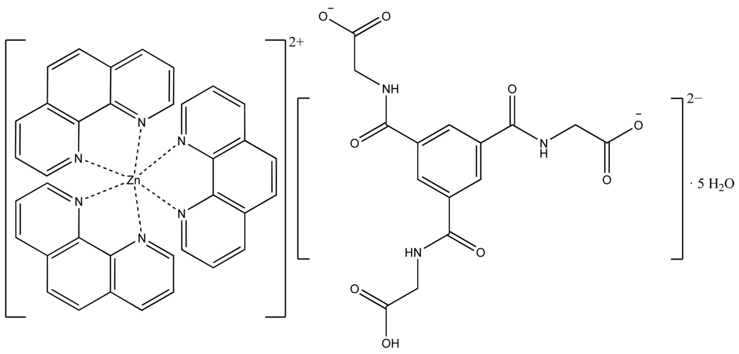
Supramolecular Structure of Tris(1,10-phenanthroline)zinc(II)-Cation and N,N′,N″-tris(carboxymethyl)-1,3,5-benzenetricarboxamide-Anion: Synthesis, Crystal Structure, Vibrational Spectra, and Theoretical Investigations

by
Niels-Patrick Pook
Institute of Inorganic and Analytical Chemistry, Clausthal University of Technology, Paul-Ernst-Str. 4, D-38678 Clausthal-Zellerfeld, Germany
Crystals 2023, 13(4), 569; https://doi.org/10.3390/cryst13040569
Submission received: 7 March 2023 / Revised: 21 March 2023 / Accepted: 24 March 2023 / Published: 27 March 2023

Abstract

:
The present work reports on the synthesis, structural, spectroscopic, and theoretical studies of a new solid state ionic compound mainly composed of tris(1,10-phenanthroline)zinc(II) cations and N,N′,N″-tris(carboxymethyl)-1,3,5-benzenetricarboxamide anions. Colorless and well-shaped crystals were obtained from an alkaline aqueous methanolic solution, and single-crystal X-ray diffraction revealed a distinct supramolecular network. Powder diffraction techniques and Rietveld analysis confirmed the phase purity of the crystalline probes. The compound crystallizes in the orthorhombic space group Pbca with a cell volume of 9517.0 Å3. The complex cations [Zn(phen)3]2+ are interconnected via π–π-interactions and form a cationic layer network with holes. The organic counterion, as a dianion, forms dimeric units through π–π-interactions and hydrogen bonds, which also form an anionic layer network with honeycomb-like holes through cooperative classical hydrogen bonds of the O∙∙∙H–O and O∙∙∙H–N type with attractive secondary electrostatic interactions. Using the holes, the resulting supramolecular framework can be described as an interpenetrated network of separate anionic and cationic layers linked by further weaker non-covalent interactions such as C–H∙∙∙π and lone-pair∙∙∙π interactions. DFT calculations confirmed the experimentally observed spectroscopic (IR and Raman) findings. For a deeper insight into the structural arrangement in the crystal, the different Hirshfeld surfaces of the cation and anion, the pairwise interaction energies as well as the energy framework were calculated, supporting the dominance of attractive and repulsive electrostatic forces between the ions.

1. Introduction

Intermolecular interactions are of crucial importance and play a central key role in a multitude of biologically and medically relevant processes. Impressive examples of these biologically essential processes and structures from nature include the assembly of the DNA [1,2,3,4] and the associated reproduction of genetic information, the bio-enzymatic catalysis of proteins, protein folding itself, or the impressive self-assembly of the tobacco mosaic virus [5,6]. Underlying many of these fascinating mechanisms of assembly and reaction sequences is a high degree of efficiency in which the involved molecules recognize each other over a complex interplay of several relatively weak non-covalent forces, leading in a controlled manner to complex structures with often remarkable stability.
The associative self-assembly in the DNA double helical structure is based on the formation of classical hydrogen bonds with attractive secondary interactions [7,8,9,10,11] between the different nucleic base pairs of two DNA single strands as well as π–π stacking interactions between the superimposed base pairs [4], which provide an additional contribution to the overall stability of the system.
In addition to the intermolecular forces mentioned so far, other important non-covalent interactions exist such as the attractive and repulsive electrostatic interactions between ions, the non-classical hydrogen bonds, the lone-pair∙∙∙π and the C–H∙∙∙π interactions [3,12,13,14,15,16,17,18,19,20]. Of further central importance to supramolecular chemistry are the characteristic coordinative bonds between a metal atom and organic ligands known from transition metal complexes. One biologically important representative is adenosylcobalamine, also known as coenzyme B12 [1,21,22]. It belongs to the group of cobalamins and is involved in various metabolic functions of the organism. The basic structure consists of a cobalt complex, in which the cobalt shows an octahedral coordination environment. Four of the six coordinative bonds are formed by a corrin ring system. This complex exhibits very high stability. A related structure is found in the heme unit of hemoglobin. This iron porphyrin complex is responsible for oxygen transport in vertebrates [23]. There are many other impressive examples of structures and steering forces and the chemical and biological recognition of molecules. The insights and principles of molecular recognition and self-assembly form the basis of crystal engineering of artificial systems in the field of new effective drugs and functional supramolecular materials with applications in a wide variety of fields. Thus, supramolecular chemistry establishes an interdisciplinary research field of the departments of chemistry, physics, biology, and materials science.
However, with the intention to prepare new metal–organic coordination polymers (CPs) with scintillation effect [24,25,26,27,28,29,30] based on zinc as the metal center, 1,10-phenanthroline and N,N′,N″-tris(carboxymethyl)-1,3,5-benzenetricarboxamide (TCMBT) as ligands, the present compound was synthesized. Although the compound does not exhibit a scintillation effect under the chosen excitation conditions [31,32], it is a structurally highly interesting compound of academic interest. Several aspects of self-assembly were considered in the synthesis strategy. On the one hand, the use of the nitrogen-containing 1,10-phenanthroline as an electron-poor aromatic ligand, which is known for π-π stacking [33,34,35,36] and lone-pair∙∙∙π [3,15,18,19,37] interactions, and on the other hand, the organic ligand N,N′,N″-tris(carboxymethyl)-1,3,5-benzenetricarboxamide (TCMBT) which forms very stable dimers [38,39,40,41,42,43] via π–π stacking and cooperative hydrogen bonds. An overview of the complexes synthesized in which TCMBT acts as bridging and coordinating ligand can be found in the literature [44]. Due to the postulated scintillation mechanism of metal–organic compounds [24,26,27], the use of metal centers with high Z for the high energy conversion process and aromatic compounds (delocalized π-electrons) for an induced fluorescence by the attenuated radiation is preferred.
In the present compound, TCMBT is a doubly deprotonated counter anion and does not coordinate the metal center as shown in Scheme 1. The anions are connected by a distinct network of cooperative hydrogen bonds and hydrogen bonds with attractive secondary electrostatic interactions. They form layers with honeycomb-like holes. Through a SciFinder research, we assume that this coordination mode of TCMBT is structurally described for the first time. The cationic complexes are connected by π–π interactions and also form layers with holes. An interpenetrating network of the separated anion and cation layers is constructed over these holes. The layers are linked by further weaker non-covalent interactions such as C–H∙∙∙π, lone-pair∙∙∙π and C–H∙∙∙O hydrogen bonds.

2. Materials and Methods

2.1. Synthesis of the Compound

Cesium carbonate (3 mmol), 1,10-phenanthroline (1 mmol) and N,N′,N″-tris(carboxymethyl)-1,3,5-benzenetricarboxamide (1 mmol) were dissolved in a 1:1 (v/v) mixture of water and methanol (60 mL). The mixture was heated and stirred for 1 h. After cooling to room temperature, 10 mL of an aqueous solution of zinc(II) nitrate (1 mmol) was slowly added under continuous stirring. Good quality colorless block-shaped crystals of the compound suitable for X-ray crystallography could be obtained after five days by slow evaporation under ambient conditions. C51H47N9O14Zn Yield: 62%; Elemental analysis: Calc.: C 56.96 H 4.41 N 11.44; Found: C 56.41 H 4.31 N 11.28.

2.2. Single-Crystal X-ray Crystallography

The data set for a well-shaped single crystal selected under a polarization microscope was obtained at 223 K on a Stoe IPDS II diffractometer using a graphite monochromated MoKα radiation (λ = 0.71073 Å). The crystal was separated from the mother liquor and placed in a glass fiber with perfluorinated oil. The structure was solved by direct methods and refined using least-square methods on F2 with the SHELX-2018 [45] software package. The final structure was checked and validated with PLATON [46,47,48,49]. A validation report and a checkCIF file can be found in the Supplementary Information (SI). The atomic displacement parameters for non-hydrogen atoms were refined anisotropically, and all C-bound and N-bound H atoms were set to idealized geometry and refined isotropically with Uiso(H) = 1.2 Ueq(C and N), C–H(aromatic) = 0.94 Å and C–H(methylene) = 0.98 Å N–H(amide) = 0.87 using the riding model. The H atoms of the water molecules were located in a difference-Fourier map and were also refined isotropically with Uiso(H) = 1.5 Ueq(O). Some water molecules were restrained with the DFIX command to 0.87Å which led to a stable hydrogen bonding network. Details of the restrain can be found in the embedded INS-file of the CIF-file. A numerical absorption correction was applied using the STOE software X-Area and X-Red. Figures were prepared with DIAMOND [50] and POV-RAY [51]. Further details of the compound may be obtained free of charge from the Cambridge Crystallographic Data Centre (https://www.ccdc.cam.ac.uk/structures/) on quoting the deposition number CCDC 2234251.

2.3. Powder X-ray Diffraction (PXRD)

The phase purity of the crystalline powder probes of the newly synthesized compound were confirmed by powder diffraction techniques before all other measurements were carried out. PXRD data were collected on a STOE STADI P X-ray powder diffractometer in the Debye–Scherrer geometry with a position-sensitive detector and a germanium monochromated Cu-Kα radiation (λ = 1.54056 Å) at room temperature. Standard measurements were carried out with a generator voltage of 40 kV and a current of 30 mA and a two theta step size of 0.01° with a step width of 0.7° over an angular range of 3–91°. A measuring time of 50 s for each step leads to a total time of two hours for a single range. Eight ranges were measured and added to lower the background noise. Data were collected, analyzied, and visualized with the Stoe WINXPOW software, and the JANA2006 program package [52] was used for the leBail and Rietveld refinement procedure.

2.4. Infrared and Raman Spectroscopy

FT–IR and FT–Raman spectra were recorded with a Bruker VERTEX 70V. A U-shaped silicon carbide piece was used for infrared excitation, and a DLaTGS detector served as the detector unit. For the measurement of the Raman spectrum a Nd:YAG laser (1064 nm) with a maximum power of 1000 mW and a germanium detector was used. The analysis of the recorded IR and Raman spectra were performed using the Bruker OPUS software package.

2.5. Computional Chemistry

Theoretical calculations of the molecular energies, the structure optimization and the IR and Raman spectra were performed with the ORCA 4.0.1 program package [53]. The Hirshfeld surfaces [54,55,56] with the associated fingerprint plots [57,58], the pairwise interaction energies and the energy framework [59,60] were generated with the CrystalExplorer program package [61]. The calculations of the pairwise non-covalent interaction energies between the phenanthroline ligands of the cationic complexes, the phenanthroline ligands and the TCMBT dianion, and the TCMBT dianions were performed using the symmetry-adapted perturbation theory (SAPT) of the PSI4 software [62] with the basis sets of jun-cc-pVDZ and aug-cc-pVDZ, respectively. Further details on the used functionals and basis sets can be found in the associated sections. For all theoretical calculations the initial atomic coordinates were taken from the CIF-file.

2.6. Thermal and Elemental Analysis

The thermogravimetric analysis was performed using a TGA951 from TA Instruments Inc. The temperature range for the TGA measurements was from room temperature to 920 °C, with a heating rate of 10 K/min. The samples weighed 4.4090 mg and were measured in a platinum crucible under an argon atmosphere with a flow rate of 50 mL/min. For the elemental analysis, approximately 2 mg of the solid sample were weighed into a thin-walled tin boat, enclosed, and introduced into the Vario EL elemental analyzer from Elementar Analysesysteme GmbH.

3. Results

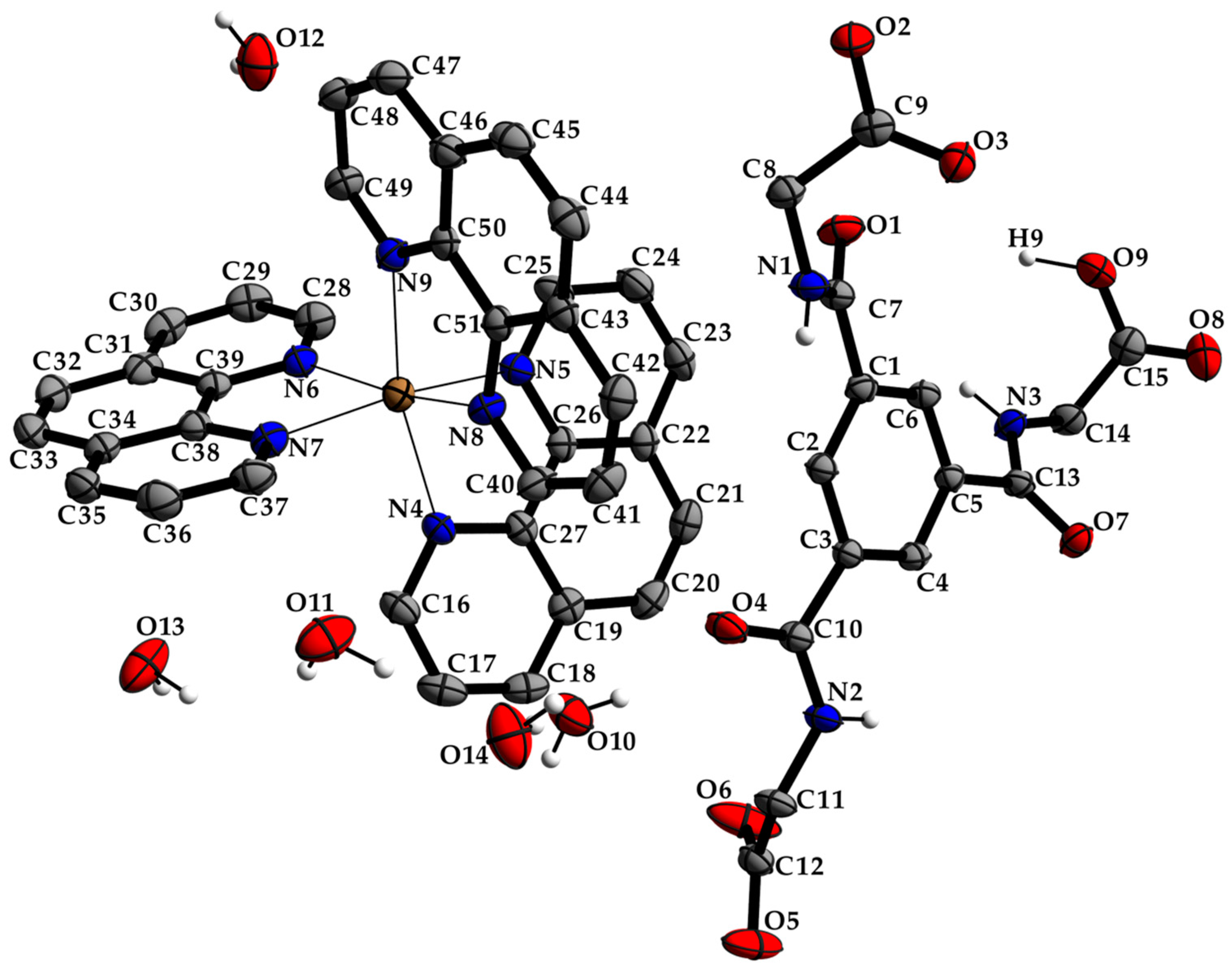
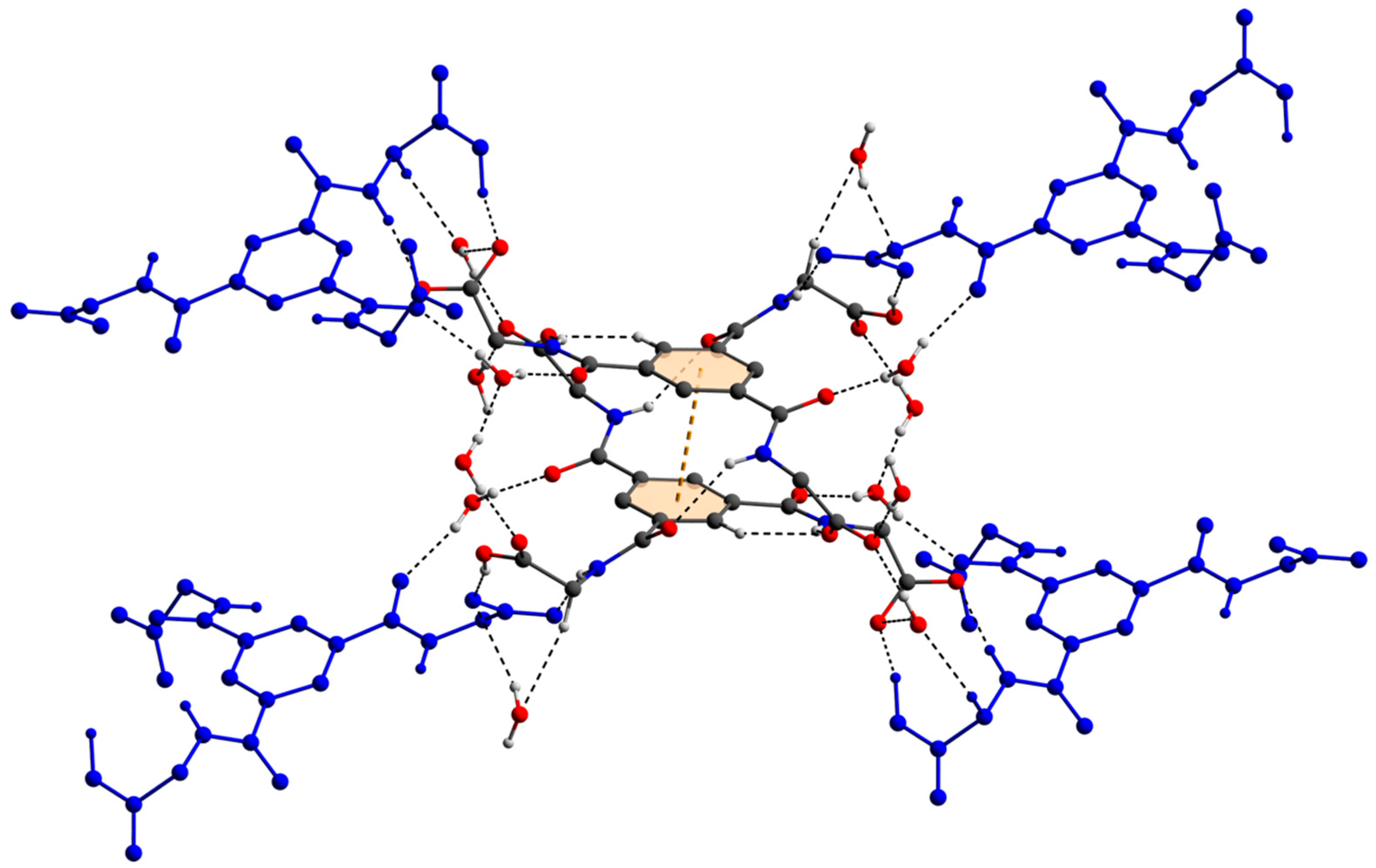
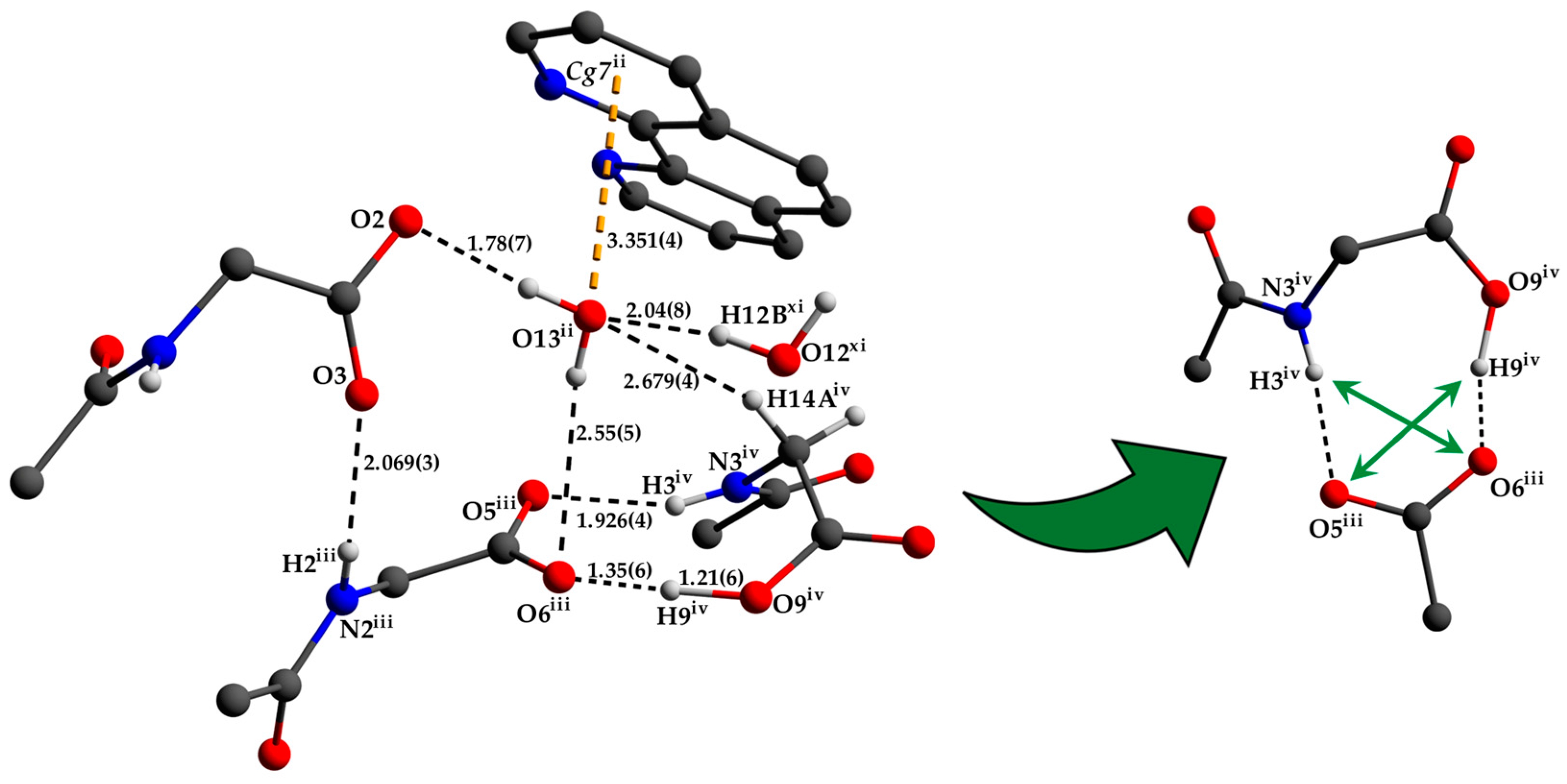
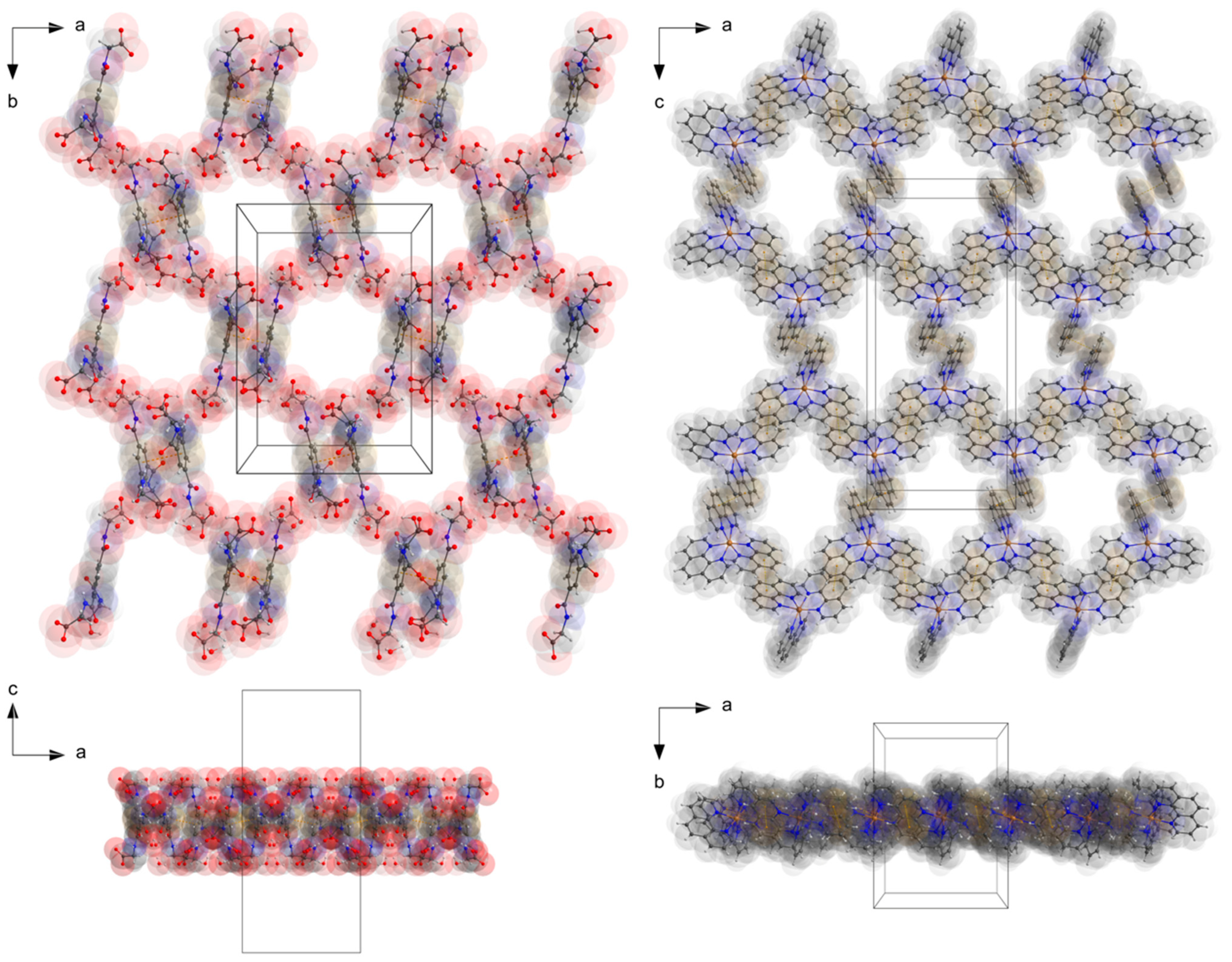
3.1. Description of the Crystal Structure

The single-crystal X-ray crystallography of a colorless block-shaped crystal grown in an alkaline aqueous-methanol solution revealed a complex cation [Zn(phen)3]2+ with a zinc(II) coordination center of a distorted octahedral coordination environment consisting of three bidentate 1,10-phenanthroline ligands, a non-coordinating doubly deprotonated N,N′,N″-tris(carboxymethyl)-1,3,5-benzenetricarboxamide (TCMBT) counter anion, and five water molecules as depicted in Figure 1. The compound crystallizes in the primitive centrosymmetric orthorhombic space group Pbca (No. 61) with eight formulas units per unit cell and a cell volume of 9517.0 Å3. Further details of the single-crystal X-ray analysis and the structure refinement are listed in Table 1. Selected bond length and angles of the known cationic complex and the dianion can be found in the Tables S1 and S2 of the SI, respectively. The values are comparable to those found in the literature [39,63].
The two deprotonated carboxylate groups of the dianion show bond lengths of C9–O2 = 1.267 (5) and C9–O3 = 1.259 (5) Å as well as C12–O5 = 1.248 (6) and C12–O6 = 1.234 (6) Å and bond angles of O2–C9–O3 with 125.7 (4)° as well as O5–C12–O6 with 124.5 (4)°, respectively. This arrangement indicate a delocalized anionic charge. It becomes clearer by the comparison to the protonated carboxylate group which shows a signifcant different bond distance of C15–O8 = 1.218 (6) and C15–O9 = 1.311 (6) Å which are in the expected ranges [64] and identify a double and a single bond. The bond angle of O8–C15–O9 with 121.0 (4)° is decreased compared to the deprotonated carboxylate groups. The illustration of Figure 2, Figure 3 and Figure S1 and Video S1 display the involvement of the carboxylates, amides and several C–H groups of the TCMBT in classical and non-classical hydrogen bonding interactions. A detailed overview of the hydrogen bond geometry is summarized in Table S3 of the SI. As seen, the dianions form dimeric units by π–π stacking and hydrogen bonding. These dimeric units are linked through further hydrogen bonds of a cooperative nature and with attractive secondary electrostatic interactions (Figure 3), leading to a supramolecular anionic layer with honeycomb-like holes (Figure 4). The hydrogen bonds of the anion linkage of the protonated and deprotonated carboxylates and N–H group of O5∙∙∙H3–N3 and O6∙∙∙H9–O9, have donor and acceptor distances of 1.926 (4) and 1.35 (6) Å, and angles of O5–H3–N3 and O6–H9–O9 with 158.4 (3)° and 164.8 (5)°, respectively. The short O6∙∙∙O9 distance of 2.544 (6) Å and the oxygen-hydrogen distance of O9–H9 of 1.21 (6) Å, which is greatly elongated, indicate a strong hydrogen bond (Figure 3.). This is known from the literature [65,66,67,68,69,70,71,72]. The diagonal relationships of the secondary stabilizing interactions show distances of H3∙∙∙O6 and H9∙∙∙O5 with 2.887 (4) and 2.77 (6) Å, respectively. These attractive diagonal interaction between the parallel hydrogen bonded bridges of O5∙∙∙H3–N3 and O6∙∙∙H9–O9 with a DD/AA motif supports and strengthens the hydrogen bonding of the anionic connection. These type of secondary interactions are observed in the hydrogen bonding of the nucleic base pairs of the double-stranded DNA [7,8,9,10,11,73]. In addition to the classical and non-classical hydrogen bonding, a further important role in the architecture of the present supramolecular structure is played by the different π-stacking interactions. As mentioned earlier, two TCMBT molecules interact with a π–π stacking in nearly perfect alignment of a face-to-face arrangement, showing a relatively short Cg1∙∙∙Cg1 centroid-to-centroid distance of 3.5382 (2) Å [4,13,14,33,34,35]. A detailed overview of the definition of the centroids is shown in Figure S2 of the SI. Furthermore, the cationic complexes also exhibit π-stacking interactions, resulting in three-dimensional linkage (Figure S3) and the formation of cationic layers with holes (Figure 4). A supramolecular framework is formed over the holes, which can be described as an interpenetrating supramolecular network of separate anionic and cationic layers. These layers are linked via further non-covalent interactions such as lone-pair∙∙∙π (Figure 3) and C–H∙∙∙π (Figure S4). Compared to the π–π stacking of the dianions, the cationic stacking show an offset or parallel displaced motif. The centroid-to-centroid distance of Cg3∙∙∙Cg3 of two phenanthrolines 1 is 3.5544 (1) Å, which is slightly shorter than the distance of Cg6∙∙∙Cg9 of phenanthroline 2 and phenanthroline 3 with a value of 3.5686 (2) Å. A closer look at the π-stacking interactions of the phenanthrolines reveals that the π–π repulsion, which is more pronounced in the dianion stacking, was minimized by the slipped arrangement of the phenanthrolines, and the π–σ attraction is favored due to the positively charged ring carbons or the C-bounded hydrogen atoms [4,33]. Basically, a transition from π–π stacking to C–H∙∙∙π interaction can be observed. The nitrogen-containg ligands as electron poor aromatic compounds are predestinated for π-stacking. When a metal atom is coordinated by the phenanthroline, the electron density of the aromatic system decreases even more due to the electron-withdrawing property of the metal, and partial charge separation occurs. This favors the van der Waals attraction of dipole–dipole interactions. For this reason, the phenanthroline ligands are usually stacked with a 180° rotation.
However, the distance of the hydrogen atom H21 of the Cg3 centroid of the phenanthroline 1 and the centroid Cg1 of the dianion (Figure S4) of 3.3033 (1) Å indicate rather an attractive interaction of the positively charged C-bounded hydrogen atom and the aromatic system and thus a C–H∙∙∙π interaction. This is supported by a comparison of the distance of the centroids Cg1 and Cg3 with a distance of 4.4404 (2) Å, which is no longer in the usual range of distances of π–π interactions. The observed geometry of the C–H∙∙∙π interactions is in good agreement with the literature values [36,74]. The pairwise energy calculations based on SAPT of the PSI4 program package [62] show the largest energy gain in the interaction of phenanthroline 1 and the dianion. The pairwise interaction energy calculation results for the phenanthrolines and the phenanthrolines with the dianion can be found in Table S4 of the SI.
The lone-pair of the O13 water molecule interact with the aromatic system of the centroid Cg7 of the phenantroline 2. The measured distance between O13 and the centroid Cg7 is 3.351 (4) Å and comparable with the literature [15,18]. Due to the cooperative nature of this water molecule’s involvement in hydrogen bonding and further weak interactions, the hydrogen bond distance of H13B to the hydrogen bond acceptor is greatly extended (Figure 3).

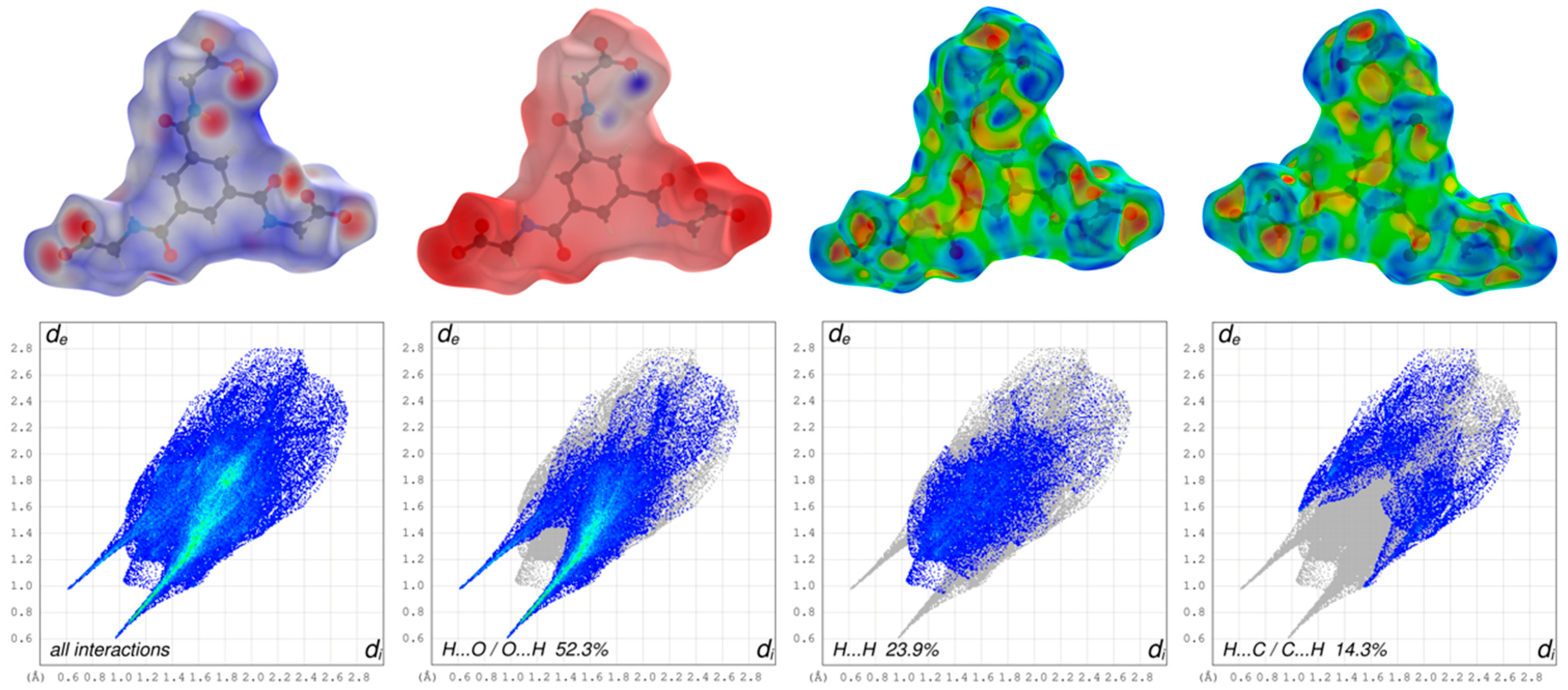
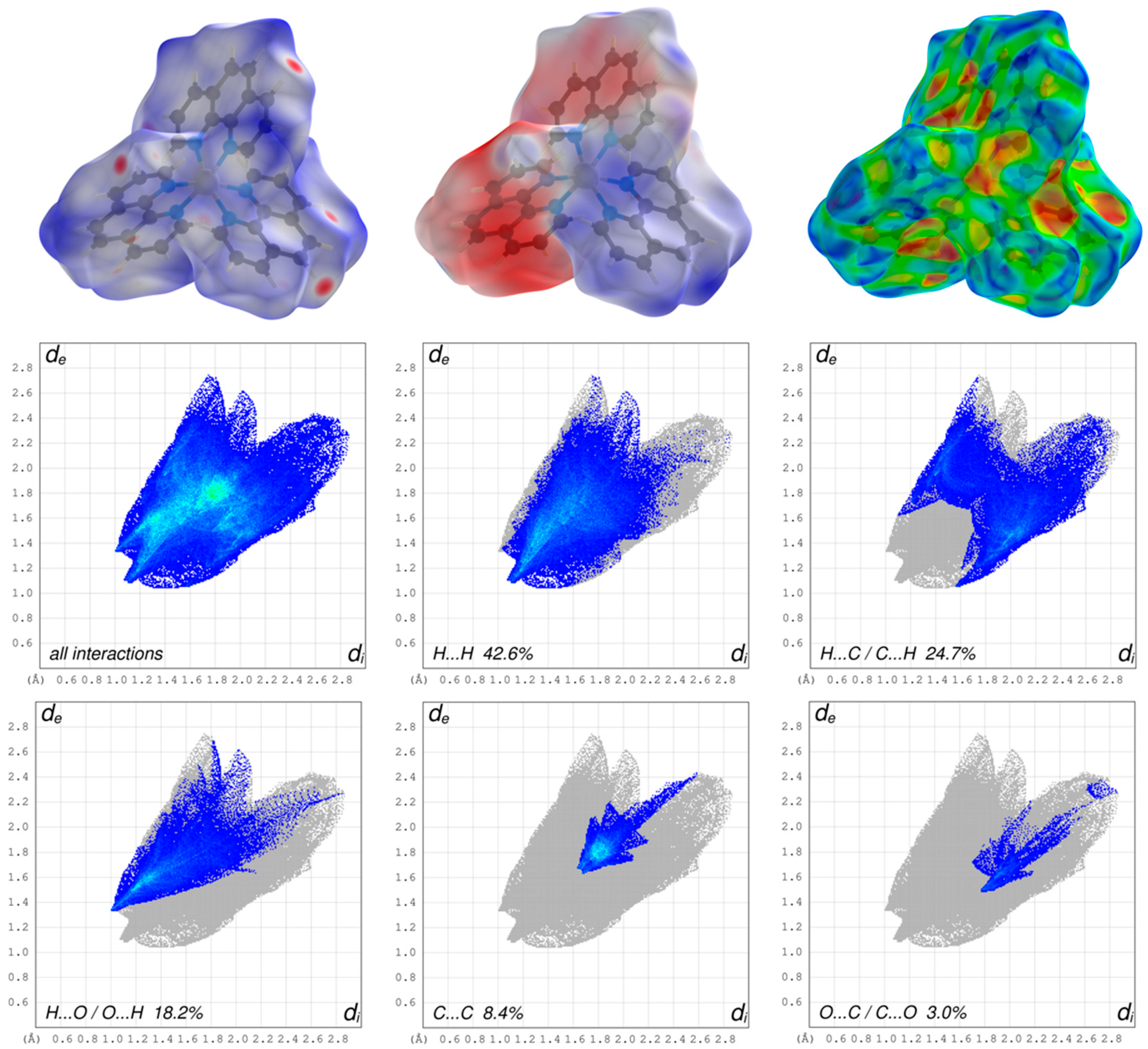
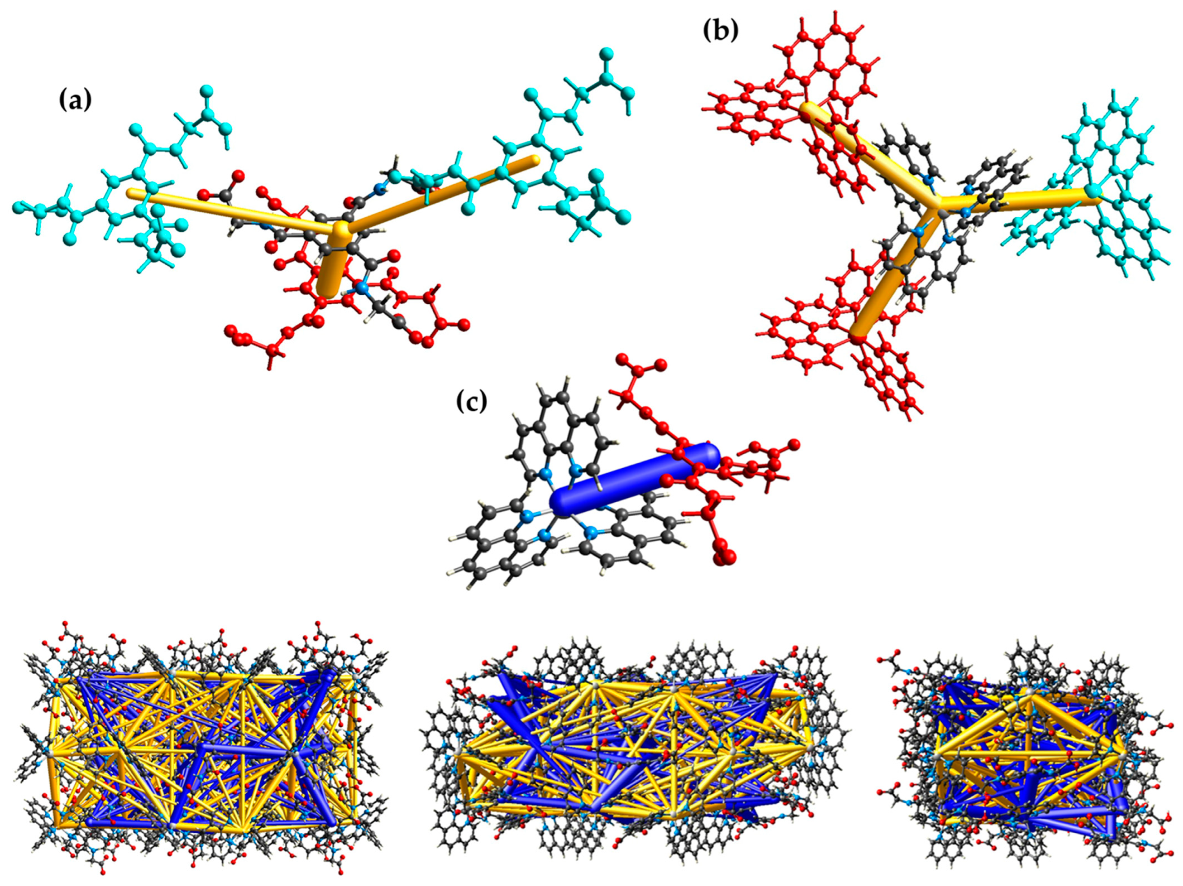
3.2. Hirshfeld Surface Analysis, Pairwise Interaction Energies and Energy Framework

In order to describe and understand the composition of the different weak interactions in supramolecular architectures of crystals, Hartree–Fock (HF) and Density Functional Theory (DFT) can be used. These quantum mechanical modelling methods are employed in chemistry and physics as well as in related scientific research fields of material science for calculating electronic structures, spectra, and energies of molecules. The visualization of the results in form of orbitals of the different theories (e.g., MOs, NBOs, etc.) and the molecule surfaces [55,75] gain a deeper insight into the weaker interactions in the crystals, and the findings can be utilized in crystal engineering. Based on the mentioned methods, the CrystalExplorer [61] software offers the possibility of generating such surfaces and newly calculate of the pairwise interaction energies which form the basis for the visualization of the energy framework of the crystal [59,60]. To investigate the close contacts between the ionic molecules in the present structure, the Hirshfeld surfaces (HS) mapped over the dnorm, the electrostatic potential energy and the shape index with the associated fingerprint plots (FP) have been generated with CrystalExplorer using TONTO with standard settings and for the electrostatic potential energy with the dispersion corrected hybird functional B3LYP and the 6-311G(d,p) basis set. To allow the viewing of all atoms and molecules around which the surface is calculated, all the surfaces are drawn transparently.
The three-dimensional HS mapped over dnorm of the cationic complex in the range –0.1974 to 1.5761 and for the dianion in the range –0.8003 to 1.6868 are shown in Figure 5 and Figure 6, respectively. The blue areas of the HS surfaces represent the longer distances than the van der Waals radii, and the white areas the close contacts equal to the sum of van der Waals radii. The red spots display closer distances than the van der Waals radii and thus indicate donors and acceptors of classical and non-classical hydrogen bonding. The big bright-red spots reveal the types of O–H···O as the stronger classical hydrogen bonds of the dianion, whereas the smaller and lighter red spots reveal the non-classical hydrogen bonds of the type C–H···O of the aromatic C-bounded hydrogens of the cationic complex and the dianion.
The appearance of the small single spike in the corresponding FP of the cationic complex in the region de ~1.35 Å/di~1.00 Å as well as the larger and long spikes of dianion in the region de ~0.98 Å/di~0.61 Å and de ~0.61 Å/di~0.98 Å confirm the presence of the hydrogen bonding, respectively. The di and the de are defined as the internal and external distances between the HS and are given in angstrom. The absence of the second spike and the blue region in the FP of the close contacts of hydrogens and oxygens of the cationic complex reveals that the cationic complex only acts as a hydrogen bond donor. The HS mapped over the electrostatic potential energy verifies the role of donor and acceptor functions in the hydrogen bonding network. The transparent HS of the complex cation in the range –0.0320 to 0.0471 and the dianion in the range –0.3274 to 0.1925 are depicted in Figure 5 and Figure 6, respectively. The blue spots are assigned to the hydrogen bond donors of the aromatic C-bounded hydrogens of the cationic complex. The region around the protonated oxygens of the carboxylate group of the dianion and the nitrogen of the amides show also big blue spots and, therefore, indicates the hydrogen bond donor function. The big red spots of the HS in the region around the deprotonated oxygens of the dianion can be assigned to the hydrogen bond acceptors. In addtion, the three-dimensional deformation density maps of the dianion and the phenathrolines were also plotted using CrystalExplorer and are illustrated in Figure S6 of the SI.
The deformation energy may reveal the presence of charge depletion directed to the region of charge concentration. In a comparison of the main contributions to the HS of the complex cation and dianion, it is striking that the close contacts of the cation, which are attributed to the non-classical hydrogen bonding of H···O/O···H (18.2%), are decreased to the values of the dianion of classical and non-classical hydrogen bonding of H···O/O···H (52.3%) with a simultaneously increasing of the close contacts of H···H (42.6%) of cationic complex and H···H (23.9%) of the dianion. This difference is due to the fact, that the hydrogen bonding of the cationic complex has only a donor nature and is more involved in π–π stacking interactions as well as the high number of the H atoms of the phenantroline ligands of the cationic complex. Therefore, the close contacts of C···C (8.4%) of the cationic complex is increased to the C···C (5.6%) close contacts of the dianion. In general, the blue–red triangles in the three-dimensional HS mapped over the shape index indicate π–π stacking interactions of aromatic compounds and moities. Figure 5 shows a blue–red triangle of the HS mapped ovre the shape index on one side of the dianion and an orange deformation of the surface on the other side. This corresponds to the π–π stacking interactions of two dianions leading to the dimeric anion units. The deformation of the HS is caused by the hydrogen atom of the phenanthroline 1 which is involved in C–H∙∙∙π interaction with the dianion (Figure S4). The mentioned triangles are also observed by the phenantrholines of the cationic complex. For a better overview, the HS mapped over the shape index for all phenanthrolines and with both sides are given in Figure S5 of the SI. A detailed look shows that all phenanthroline ligands have blue–red triangles and, therefore, are involved in π–π stacking interactions. Phenanthroline 2 and phenanthroline 3 have a orange colored deformation on the surface. This indicates the C–H∙∙∙π interaction of the phenanthrolines and is in agreement with the single-crystal structure analysis (Figure S4).
CrystalExplorer has also been used for the intermolecular energy calculation based on the CE-B3LYP/6-31G(d,p) and CE-B3LYP/DGDZVP level of theory for the crystal monomers, respectively, and to visualize the pairwise interaction energies and the three-dimensional energy frameworks of the present compound (Figure 7). The calculated pairwise interaction energy details are summarized in Table S5 of the SI, and the energy framework divided into the electrostic, dispersion and total energy is depicted in Figure S7. The total energies are only reported for two benchmarked energy models which are the sum of the four energy components and scaled appropriately [60]. The pairwise interaction energies and the associated energy framework exhibit the dominance of attractive and repulsive electrostatic forces between the counter ions.

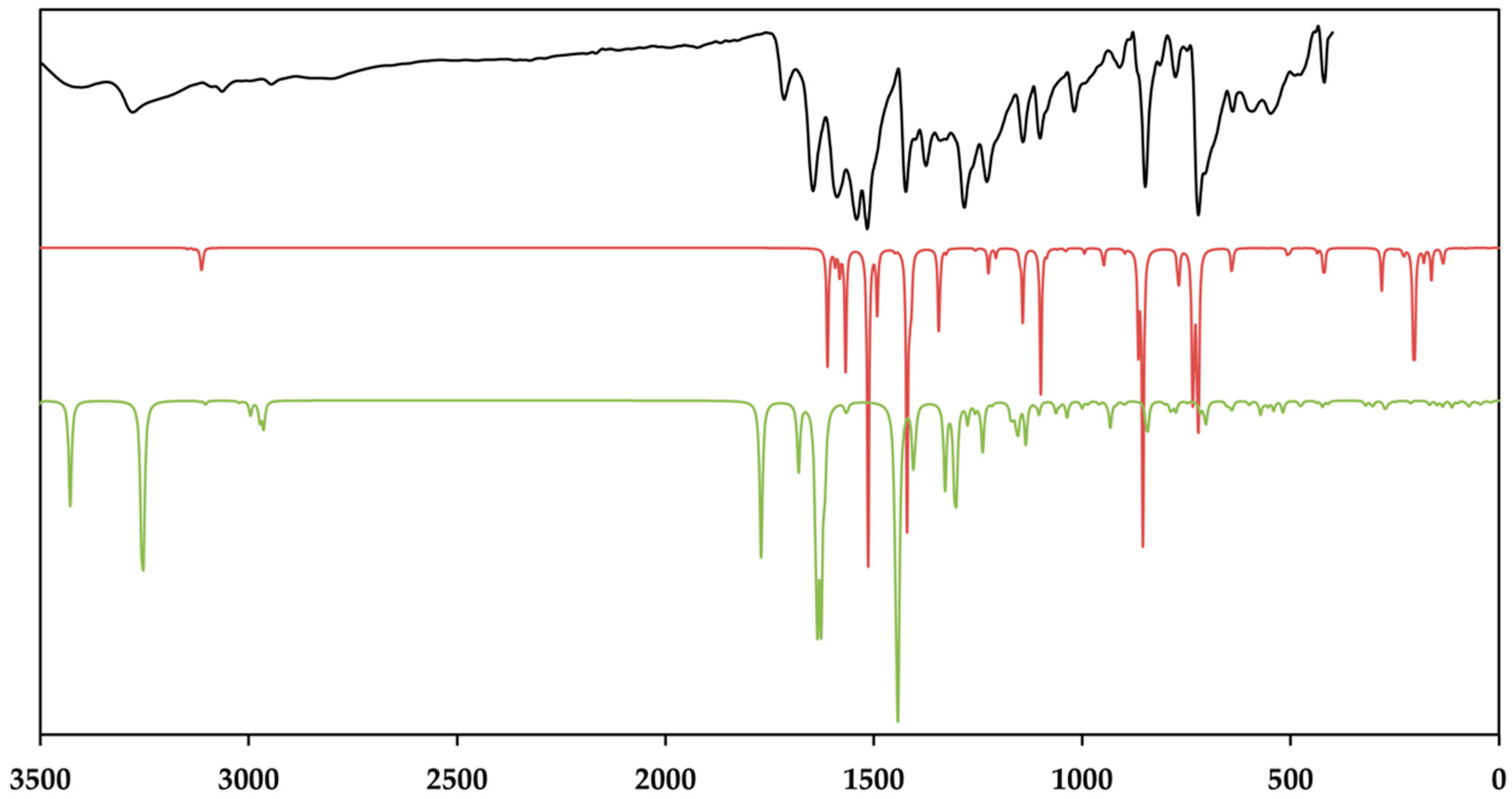
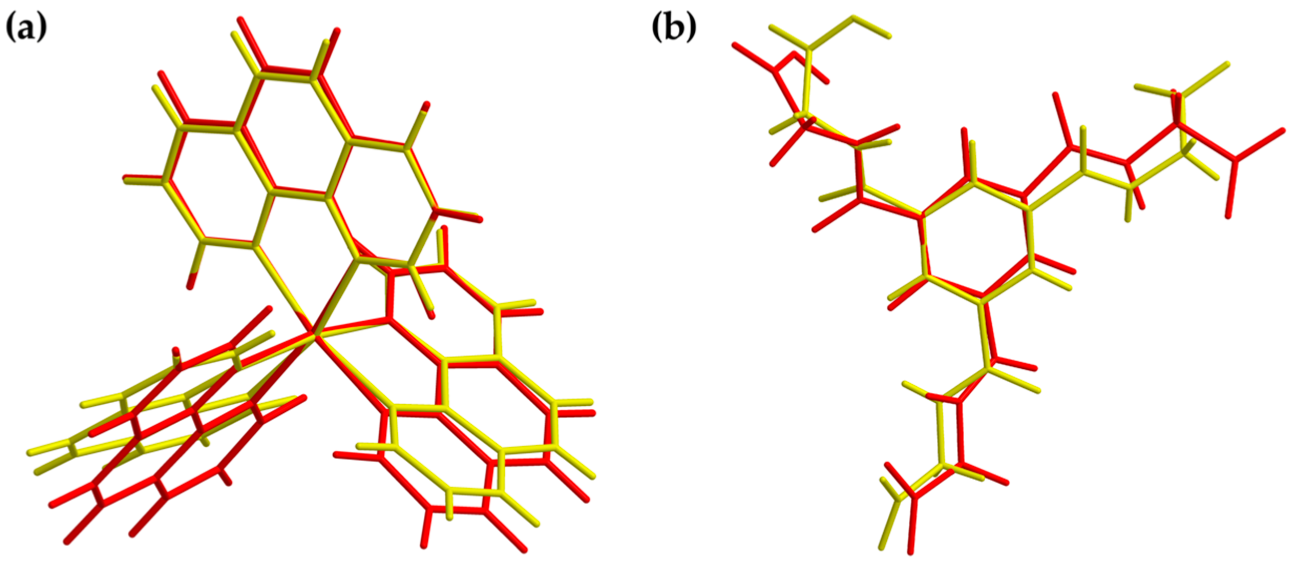
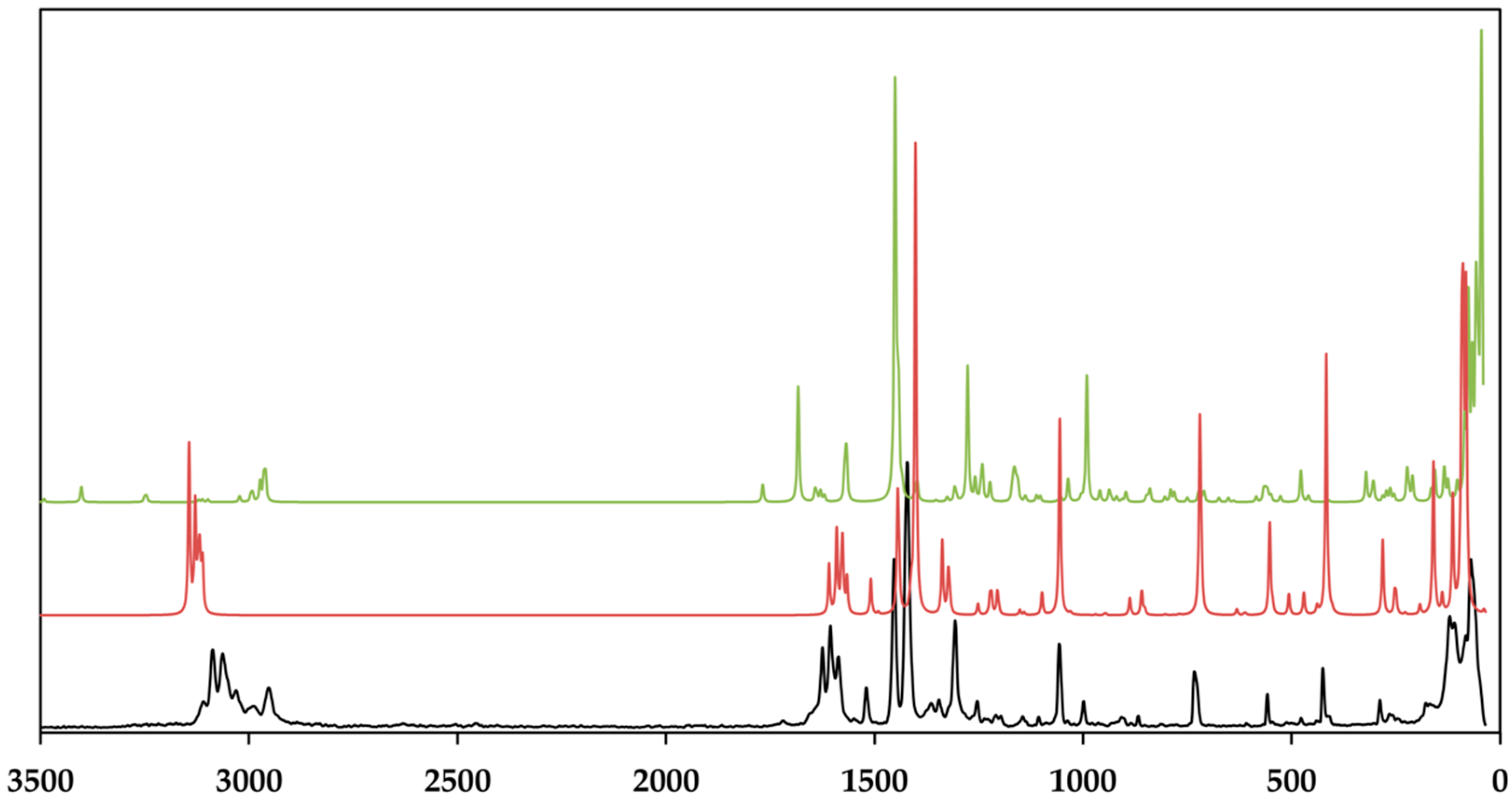
3.3. Vibrational and Theoretical Spektra

For all the theoretical calculations, the density functional programs provided by the ORCA 4.0.1. [53] package was used. Before the spectra were calculated, the structures were optimized to avoid a convergence to a saddle-point leading to negative frequencies. The optimization results are presented in Figure 8 and Figure 10 wherein the original structures of the cationic complex and dianion based on the crystal structure coordinates are colored in yellow, and the optimized structures were colored in red. All calculations were carried out using the pure density, local, and gradient corrected functionals of Becke and Perdew, which is known as BP86 [76] and provide excellent geometries and vibrational spectra in most cases. The def2 basis sets of the Karlsruhe group of TZVPP and TZVP [77] were employed for the infrared and Raman spectra calculations, and the def2/J auxiliary basis [78], including the RI approximation, was used for the coulomb fitting, respectively, featuring a valence triple-zeta basis set with polarization functions on all atoms. For the unrestricted theoretical calculations of the anion spectra, the diffuse and minimally augmented basis sets were used [79]. The resulting theoretical spectra are compared with the measured ones as depicted in Figure 9 and Figure 11, wherein the lines of the theoretical spectra of the cationic complexes are colored in red and the lines of the dianion are colored in green. The room temperature baseline-corrected FT–MIR spectrum was measured in the range of 3600 and 400 cm−1, and the Raman spectrum was measured in the range of 3600 and 0 cm−1, respectively. The lines of the measured spectra are colored in black.
As depicted in Figure 9, the measured infrared spectrum shows two broad absorption bands in the region of 3404 and 3278 cm−1 with a sharper intensity due to the asymmetric and symmetric O–H stretching vibrations of the lattice water and the secondary amide of the amide groups. It is evident that these bands have a sharp character in the theoretical spectrum. This fact can be explained by the absence of the hydrogen bonds between the lattice water and the amines of different strength, which broaden these bands [80,81]. The aromatic C–H stretching vibrations of TCMBT and the phenanthroline occur in the range of 3109 and 3089 cm−1 and followed by the asymmetric and symmetric stretching vibrations of the methylene group of the side chain of the TCMBT in the region of 2969 and 2946 cm−1 in the infrared and Raman spectra. As a result of the strong hydogen bonding of the carboxylate groups, the very weak broad absorption at 2806 cm−1 in the infrared spectrum may thatindicate the O–H stretching vibrations of the carboxylate group, which is underpinned by non-appearance in the calculated spectrum of the dianion [82]. A further indication is provided by the occurrence of the vibration bands located at 1715 cm−1 of a medium intensity in the infrared spectrum and at 1719 cm−1 of a very weak intensity in the Raman spectrum, which derive from the out-of-phase and in-phase C=O stretch in dimers [83], or it may indicate symmetric C=O stretching vibrations [82]. The appearance of the absorption at 1646 cm−1 in the infrared and 1625 cm−1 in the Raman spectrum is associated with the C=O stretching of the carbonyl and/or carboxylate group.
However, the spectra are dominated by the vibrations of the aromatic rings and the associated groups. The metal-nitrogen stretches are found in the region of 400–180 cm−1, and the assignments can be found in the literature [84,85]. The vibrational modes below 180 cm–1 are caused by the lattice vibrations. The full vibrational assignments of the phenanthroline have been described earlier [86,87,88,89]. Due to the symmetry of the cationic complex, the Raman spectrum is dominated by the vibrations of this complex. It must be noted that the findings from the single-crystal structure analysis correspond very well with those of the measured and calculated spectra.

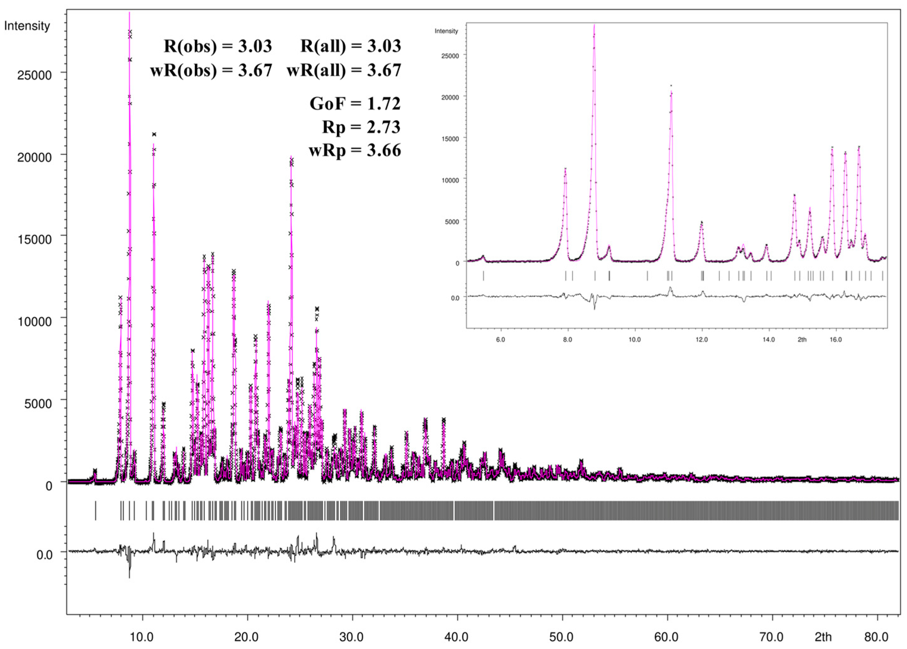
3.4. Rietveld Refinement

For the Rietveld refinement procedure and visualization of the refinement results the JANA2006 program package [52] was used. Figure 12 gives a graphically summarized overview of the Rietveld refinement results. For the refinement the CIF file informations of the single-crystal X-ray crystallography loaded with JANA 2006 and during the LeBail fitting and profile matching the parameters of the scale factor, background, unit cell parameters, as well as peak shape, width, and peak symmetry were refined. The pseudo-Voigt function was used for the description of the line shape of the diffraction peaks, and the low theta peak asymmetry were corrected by the divergence correction method. The asymmetry fitting results are presented in the small window of Figure 12 and show a very good agreement with the peak shape of the measured powder diffraction pattern. All mentioned parameters were refined during the following Rietveld refinement procedure expecting the anisotropic displacement parameters, atomic distances, and angles which were fixed to the ones of the single-crystal structure refinement. As shown in the difference profile of the Rietveld refinement (black line), the calculated and measured intensities exhibit a very good correlation. Additionally, all intensities were included in the refinement. Based on the standard quality criteria of the R-values and the goodness-of-fit, the Rietveld refinement yields excellent agreement with the results of the single-crystal structure determination.

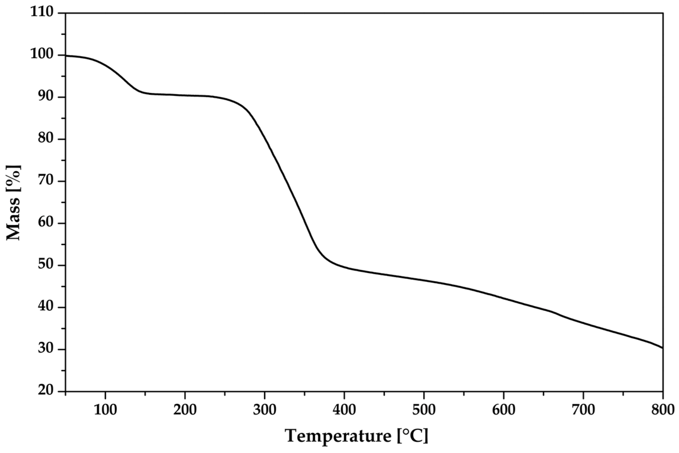
3.5. Thermal Analysis

To evaluate the thermal stability of the new compound, its thermal behavior was examined using thermogravimetric analysis (TGA) (Figure 13). A weight loss of 8.7% was observed in the temperature range of 78–142 °C, which corresponds to the removal of the water molecules. Subsequently, a weight loss of 38.2% was observed in the temperature range of 245–378 °C, indicating the decomposition of the non-coordinating organic dianion (TCMBT). The additional weight loss of the sample can be attributed to the decomposition of the tris(1,10-phenanthroline)zinc(II) cation. Based on the TGA results, the tris(1,10-phenanthroline)zinc(II) cation exhibits the greatest stability.

4. Conclusions

In summary, the reaction of N,N′,N″-tris(carboxymethyl)-1,3,5-benzenetricarbox-amide (TCMBT), 1,10-phenathroline and zinc(II) nitrate in an alkaline aqueous methanolic solution leads to colorless block-shaped crystals. The single-crystal X-ray structure analysis revealed an extended supramolecular architecture mainly composed of the complex cations [Zn(C12H8N2)3]2+ and TCMBT dianions. The cationic complexes are linked via π–π stacking and form a three-dimensional cationic layer network with holes. Based on hydrogen bonding and π-stacking, the dianions form dimeric units. These units are connected through cooperative hydrogen bonds with attractive secondary electrostatic interactions, resulting in an anionic layer network with honeycomb-like holes. Based on the holes, the resulting supramolecular framework can be described as an interpenetrating network of separate anionic and cationic layers connected by further weaker non-covalent interactions such as C–H∙∙∙π and lone-pair∙∙∙π interactions. The theoretical infrared and Raman spectra were calculated with the DFT methods and confirm the experimentally observed spectroscopic findings. The analysis of the different Hirshfeld surfaces proved the key role of the hydrogen bonding and the π-interactions in the composition of the supramolecular architecture in the crystal. Moreover, the pairwise interaction energies and associated energy framework reveal the dominance of attractive and repulsive electrostatic forces between the counterions.

Supplementary Materials

The following supporting information can be downloaded at: https://www.mdpi.com/article/10.3390/cryst13040569/s1, Table S1: Selected bond lengths (Å) and bond angle (°) of the cationic complex; Table S2: Selected bond lengths (Å) and bond angle (°) of the dianion; Table S3: Hydrogen bond geometry (Å, °) for [Zn(C12H8N2)3]C15H13N3O9∙5H2O; Figure S1: View of the dimeric anions with hydrogen bonds (black dashed lines) and π–π-interaction (yellow dashed lines). The carbon hydrogen atoms have been omitted for clarity. Symmetry codes: (ii) −x + 1/2, y + 1/2, z; (iii) −x, −y + 1, −z + 1; Figure S2: Defintion of centroids of the phenantrholines of the cationic complex and the dianion with numbering, respectively. The hydrogen atoms have been omitted for clarity; Figure S3: View of the three-dimensional cationic π–π-interactions (yellow dashed lines). The hydrogen atoms have been omitted for clarity. Symmetry codes: (i) −x + 1, −y + 1, −z + 1; (ix) x + 1/2, y, −z + 1/2; (x) x 1/2, y, −z + 1/2; Figure S4: Representation of the C–H∙∙∙π interaction of the phenanthroline 1 and the dianion (left) as well as the π stacking and C–H∙∙∙π interactions of the phenanthroline 2 and 3 (right). The hydrogen atoms have been omitted for clarity. Bond lengths are given in Å. Symmetry code: (ix) x + 1/2, y, −z + 1/2; Table S4: Pairwise interaction energies (kJ/mol) calculated with PSI4 (SAPT0); Figure S5: Graphical representations of the Hirshfeld surfaces of the phenanthrolin ligands of the cationic complex drawn with transparency and mapped over the shape index; Figure S6: Graphical representations of the Hirshfeld surfaces of the dianion (upper part) and the phenanthrolin ligands of the cationic complex (lower part) mapped over the deformation density; Figure S7: Visualization of the energy framework in the crystal along the a axis (left), b axis (middle) and c axis (right) of the dispersion energy (top), the coulomb energy (middle), and the total energy (bottom); Table S5. Pairwise interaction energies of the cationic complexes and anions with color code. Interaction energy is given in kJ/mol,m and R is the distance between molecular centroids (mean atomic position) in Å; The CIF, the checkCIF and Platon output files as well as the Video S1 are included in the Supplementary Materials.

Funding

The author acknowledges financial support from the Open Access Publishing Fund of Clausthal University of Technology.

Data Availability Statement

On quoting the deposition number 2234251 at the Cambridge Crystallographic Data Centre (https://www.ccdc.cam.ac.uk/structures/) the single-crystal crystallo-graphic data set of the present compound are available free of charge.

Acknowledgments

The author is deeply indebted to A. Adam and M. Gjikaj for their support and helpful suggestions. The author thanks Karin Bode for the measurement of the IR and Raman spectra, thermal analysis and elemental analysis.

Conflicts of Interest

The authors declare no conflict of interest.

References

  1. Steed, J.W.; Atwood, J.L. Supramolecular Chemistry, 2nd ed.; Wiley: Chichester, UK, 2009; ISBN 978-0-470-51234-0. [Google Scholar]
  2. Cerný, J.; Hobza, P. Non-covalent interactions in biomacromolecules. Phys. Chem. Chem. Phys. 2007, 9, 5291–5303. [Google Scholar] [CrossRef] [PubMed]
  3. Chawla, M.; Chermak, E.; Zhang, Q.; Bujnicki, J.M.; Oliva, R.; Cavallo, L. Occurrence and stability of lone pair-π stacking interactions between ribose and nucleobases in functional RNAs. Nucleic Acids Res. 2017, 45, 11019–11032. [Google Scholar] [CrossRef] [Green Version]
  4. Martinez, C.R.; Iverson, B.L. Rethinking the term “pi-stacking”. Chem. Sci. 2012, 3, 2191. [Google Scholar] [CrossRef] [Green Version]
  5. Lehn, J.-M. Supramolecular Chemistry: Concepts and Perspectives; VCH: Weinheim, UK, 1995; ISBN 978-3-527-29311-7. [Google Scholar]
  6. Culver, J.N. Tobacco mosaic virus assembly and disassembly: Determinants in pathogenicity and resistance. Annu. Rev. Phytopathol. 2002, 40, 287–308. [Google Scholar] [CrossRef] [Green Version]
  7. Kawahara, S.; Uchimaru, T. Secondary Interaction Contribution in Hydrogen-Bonded Complex: Theoretical Model Study in Hydrogen Fluoride Trimer. J. Comput. Chem. Jpn. 2004, 3, 41–48. [Google Scholar] [CrossRef] [Green Version]
  8. Zimmerman, S.C.; Murray, T.J. Hydrogen bonded complexes with the AA·DD, AA·DDD, and AAA·DD motifs: The role of three centered (bifurcated) hydrogen bonding. Tetrahedron Lett. 1994, 35, 4077–4080. [Google Scholar] [CrossRef]
  9. Jorgensen, W.L.; Pranata, J. Importance of secondary interactions in triply hydrogen bonded complexes: Guanine-cytosine vs uracil-2,6-diaminopyridine. J. Am. Chem. Soc. 1990, 112, 2008–2010. [Google Scholar] [CrossRef]
  10. Hisamatsu, Y.; Shirai, N.; Ikeda, S.; Odashima, K. A new quadruple hydrogen-bonding module with a DDAA array: Formation of a stable homodimer without competition from undesired hydrogen-bonded dimers. Org. Lett. 2009, 11, 4342–4345. [Google Scholar] [CrossRef]
  11. van der Lubbe, S.C.C.; Zaccaria, F.; Sun, X.; Guerra, C.F. Secondary Electrostatic Interaction Model Revised: Prediction Comes Mainly from Measuring Charge Accumulation in Hydrogen-Bonded Monomers. J. Am. Chem. Soc. 2019, 141, 4878–4885. [Google Scholar] [CrossRef] [Green Version]
  12. Hobza, P.; Müller-Dethlefs, K. Non-Covalent Interactions: Theory and Experiment; Royal Society of Chemistry: Cambridge, UK, 2010; ISBN 978-1847558534. [Google Scholar]
  13. Schneider, H.-J. Binding mechanisms in supramolecular complexes. Angew. Chem. Int. Ed. Engl. 2009, 48, 3924–3977. [Google Scholar] [CrossRef]
  14. Meyer, E.A.; Castellano, R.K.; Diederich, F. Interactions with aromatic rings in chemical and biological recognition. Angew. Chem. Int. Ed Engl. 2003, 42, 1210–1250. [Google Scholar] [CrossRef]
  15. Jain, A.; Ramanathan, V.; Sankararamakrishnan, R. Lone pair … pi interactions between water oxygens and aromatic residues: Quantum chemical studies based on high-resolution protein structures and model compounds. Protein Sci. 2009, 18, 595–605. [Google Scholar] [CrossRef] [PubMed] [Green Version]
  16. Novotný, J.; Bazzi, S.; Marek, R.; Kozelka, J. Lone-pair-π interactions: Analysis of the physical origin and biological implications. Phys. Chem. Chem. Phys. 2016, 18, 19472–19481. [Google Scholar] [CrossRef] [Green Version]
  17. Wan, C.-Q.; Chen, X.-D.; Mak, T.C.W. Supramolecular frameworks assembled via intermolecular lone pair-aromatic interaction between carbonyl and pyridyl groups. CrystEngComm 2008, 10, 475. [Google Scholar] [CrossRef]
  18. Egli, M.; Sarkhel, S. Lone pair-aromatic interactions: To stabilize or not to stabilize. Acc. Chem. Res. 2007, 40, 197–205. [Google Scholar] [CrossRef] [PubMed]
  19. Jia, C.; Miao, H.; Hay, B.P. Crystal Structure Evidence for the Directionality of Lone Pair−π interactions: Fact or Fiction? Cryst. Growth Des. 2019, 19, 6806–6821. [Google Scholar] [CrossRef] [Green Version]
  20. Nishio, M. The CH/π hydrogen bond in chemistry. Conformation, supramolecules, optical resolution and interactions involving carbohydrates. Phys. Chem. Chem. Phys. 2011, 13, 13873–13900. [Google Scholar] [CrossRef]
  21. Brenig, C.; Prieto, L.; Oetterli, R.; Zelder, F. A Nickel(II)-Containing Vitamin B12 Derivative with a Cofactor-F430-type π-System. Angew. Chem. Int. Ed. Engl. 2018, 57, 16308–16312. [Google Scholar] [CrossRef] [Green Version]
  22. Eschenmoser, A. Vitamin B12: Experiments Concerning the Origin of Its Molecular Structure. Angew. Chem. Int. Ed. Engl. 1988, 27, 5–39. [Google Scholar] [CrossRef]
  23. Franck, B.; Nonn, A. Novel Porphyrinoids for Chemistry and Medicine by Biomimetic Syntheses. Angew. Chem. Int. Ed. Engl. 1995, 34, 1795–1811. [Google Scholar] [CrossRef]
  24. Doty, F.P.; Bauer, C.A.; Skulan, A.J.; Grant, P.G.; Allendorf, M.D. Scintillating Metal-Organic Frameworks: A New Class of Radiation Detection Materials. Adv. Mater. 2009, 21, 95–101. [Google Scholar] [CrossRef]
  25. Allendorf, M.D.; Bauer, C.A.; Bhakta, R.K.; Houk, R.J.T. Luminescent metal-organic frameworks. Chem. Soc. Rev. 2009, 38, 1330–1352. [Google Scholar] [CrossRef] [PubMed]
  26. Wang, C.; Volotskova, O.; Lu, K.; Ahmad, M.; Sun, C.; Xing, L.; Lin, W. Synergistic assembly of heavy metal clusters and luminescent organic bridging ligands in metal-organic frameworks for highly efficient X-ray scintillation. J. Am. Chem. Soc. 2014, 136, 6171–6174. [Google Scholar] [CrossRef] [PubMed]
  27. Wang, X.; Wang, Y.; Wang, Y.; Liu, H.; Zhang, Y.; Liu, W.; Wang, X.; Wang, S. Color-tunable X-ray scintillation based on a series of isotypic lanthanide-organic frameworks. Chem. Commun. 2019, 56, 233–236. [Google Scholar] [CrossRef]
  28. Lecoq, P. Development of new scintillators for medical applications. Nucl. Instrum. Methods Phys. Res. Sect. A Accel. Spectrometers Detect. Assoc. Equip. 2016, 809, 130–139. [Google Scholar] [CrossRef]
  29. Perry IV, J.J.; Feng, P.L.; Meek, S.T.; Leong, K.; Doty, F.P.; Allendorf, M.D. Connecting structure with function in metal–organic frameworks to design novel photo- and radioluminescent materials. J. Mater. Chem. 2012, 22, 10235. [Google Scholar] [CrossRef]
  30. Pook, N.-P. A Scintillating One-Dimensional Coordination Polymer Based on Cadmium(II), N,N′-(1,4-Phenylenedicarbonyl)diglycinate, and 2,2′-Bipyridine: Crystal Structure, Hirshfeld Surface Analysis, and Luminescence Lifetime Properties †. Solids 2021, 2, 371–384. [Google Scholar] [CrossRef]
  31. Pook, N.-P.; Fruhner, C.-J.; Franzl, T.; Denzer, U.; Adam, A. Instrumentation for X-ray Excited and Laser Induced Fluorescence Lifetime Spectroscopy Using Two-Dimensional Photon Counting. IEEE Trans. Nucl. Sci. 2012, 59, 2319–2323. [Google Scholar] [CrossRef]
  32. Pook, N.-P.; Fruhner, C.-J.; Franzl, T.; Denzer, U.; Adam, A. Further performance tests of a picosecond X-ray and laser induced streak camera system with fast scintillation materials. Radiat. Meas. 2013, 56, 281–284. [Google Scholar] [CrossRef]
  33. Janiak, C. A critical account on π–π stacking in metal complexes with aromatic nitrogen-containing ligands †. J. Chem. Soc. Dalton Trans. 2000, 21, 3885–3896. [Google Scholar] [CrossRef]
  34. Salonen, L.M.; Ellermann, M.; Diederich, F. Aromatic rings in chemical and biological recognition: Energetics and structures. Angew. Chem. Int. Ed. Engl. 2011, 50, 4808–4842. [Google Scholar] [CrossRef]
  35. Riwar, L.-J.; Trapp, N.; Kuhn, B.; Diederich, F. Substituent Effects in Parallel-Displaced π-π Stacking Interactions: Distance Matters. Angew. Chem. Int. Ed. Engl. 2017, 56, 11252–11257. [Google Scholar] [CrossRef] [PubMed] [Green Version]
  36. Lu, Z.; Gamez, P.; Mutikainen, I.; Turpeinen, U.; Reedijk, J. Supramolecular Assemblies Generated from Both Lone-Pair···π and C−H···π Binding Interactions. Cryst. Growth Des. 2007, 7, 1669–1671. [Google Scholar] [CrossRef]
  37. Li, W.; Usabiaga, I.; Calabrese, C.; Evangelisti, L.; Maris, A.; Favero, L.B.; Melandri, S. Characterizing the lone pairπ-hole interaction in complexes of ammonia with perfluorinated arenes. Phys. Chem. Chem. Phys. 2021, 23, 9121–9129. [Google Scholar] [CrossRef] [PubMed]
  38. Bose, P.P.; Drew, M.G.B.; Das, A.K.; Banerjee, A. Formation of triple helical nanofibers using self-assembling chiral benzene-1,3,5-tricarboxamides and reversal of the nanostructure’s handedness using mirror image building blocks. Chem. Commun. 2006, 30, 3196–3198. [Google Scholar] [CrossRef] [PubMed]
  39. Gong, B.; Zheng, C.; Yan, Y. Structure of N,N′,N′′-tris(carboxymethyl)-1,3,5benzenetricarboxamide trihydrate. J. Chem. Crystallogr. 1999, 29, 649–652. [Google Scholar] [CrossRef]
  40. Dokorou, V.N.; Powell, A.K.; Kostakis, G.E. Two pseudopolymorphs derived from alkaline earth metals and the pseudopeptidic ligand trimesoyl-tris-glycine. Polyhedron 2013, 52, 538–544. [Google Scholar] [CrossRef]
  41. Raynal, M.; Li, Y.; Troufflard, C.; Przybylski, C.; Gontard, G.; Maistriaux, T.; Idé, J.; Lazzaroni, R.; Bouteiller, L.; Brocorens, P. Experimental and computational diagnosis of the fluxional nature of a benzene-1,3,5-tricarboxamide-based hydrogen-bonded dimer. Phys. Chem. Chem. Phys. 2021, 23, 5207–5221. [Google Scholar] [CrossRef]
  42. Sun, R.; Li, Y.-Z.; Bai, J.; Pan, Y. Synthesis, Structure, Water-Induced Reversible Crystal-to-Amorphous Transformation, and Luminescence Properties of Novel Cationic Spacer-Filled 3D Transition Metal Supramolecular Frameworks from N, N′, N′′-Tris(carboxymethyl)-1,3,5-benzenetricarboxamide. Cryst. Growth Des. 2007, 7, 890–894. [Google Scholar] [CrossRef]
  43. Sun, R.; Wang, S.; Xing, H.; Bai, J.; Li, Y.; Pan, Y.; You, X. Unprecedented 4(2)6(4) topological 2-D rare-earth coordination polymers from a flexible tripodal acid with additional amide groups. Inorg. Chem. 2007, 46, 8451–8453. [Google Scholar] [CrossRef]
  44. Loukopoulos, E.; Michail, A.; Kostakis, G. A 12-Fold ThSi2 Interpenetrated Network Utilizing a Glycine-Based Pseudopeptidic Ligand. Crystals 2018, 8, 47. [Google Scholar] [CrossRef] [Green Version]
  45. Sheldrick, G.M. Crystal structure refinement with SHELXL. Acta Cryst C 2015, 71, 3–8. [Google Scholar] [CrossRef] [PubMed] [Green Version]
  46. Spek, A.L. Structure validation in chemical crystallography. Acta Crystallogr. D Biol. Crystallogr. 2009, 65, 148–155. [Google Scholar] [CrossRef] [PubMed] [Green Version]
  47. Spek, A.L. Checkcif validation ALERTS: What they mean and how to respond. Acta Crystallogr. E Crystallogr. Commun. 2020, 76, 1–11. [Google Scholar] [CrossRef] [PubMed] [Green Version]
  48. Spek, A.L. What makes a crystal structure report valid? Inorg. Chim. Acta 2018, 470, 232–237. [Google Scholar] [CrossRef]
  49. Spek, A.L. Single-crystal structure validation with the program PLATON. J. Appl. Crystallogr 2003, 36, 7–13. [Google Scholar] [CrossRef] [Green Version]
  50. Crystal Impact—Dr. H. Putz & Dr. K. Brandenburg GbR, Kreuzherrenstr. 102, 53227 Bonn, Germany. Diamond—Crystal and Molecular Structure Visualization. Available online: http://www.crystalimpact.com/diamond (accessed on 6 March 2023).
  51. Persistence of Vision Raytracer (Version 3.6)[Computer Software]. Persistence of Vision Pty. Ltd. 2004. Available online: http://www.povray.org/download/ (accessed on 6 March 2023).
  52. Petříček, V.; Dušek, M.; Palatinus, L. Crystallographic Computing System JANA2006: General features. Z. Für Krist. —Cryst. Mater. 2014, 229, 345–352. [Google Scholar] [CrossRef]
  53. Neese, F. Software update: The ORCA program system, version 4.0. WIREs Comput. Mol. Sci. 2018, 8, e1327. [Google Scholar] [CrossRef]
  54. McKinnon, J.J.; Mitchell, A.S.; Spackman, M.A. Hirshfeld Surfaces: A New Tool for Visualising and Exploring Molecular Crystals. Chem. Eur. J. 1998, 4, 2136–2141. [Google Scholar] [CrossRef]
  55. Spackman, M.A.; Jayatilaka, D. Hirshfeld surface analysis. CrystEngComm 2009, 11, 19–32. [Google Scholar] [CrossRef]
  56. Spackman, M.A.; McKinnon, J.J.; Jayatilaka, D. Electrostatic potentials mapped on Hirshfeld surfaces provide direct insight into intermolecular interactions in crystals. CrystEngComm 2008, 10, 377–388. [Google Scholar] [CrossRef]
  57. McKinnon, J.J.; Jayatilaka, D.; Spackman, M.A. Towards quantitative analysis of intermolecular interactions with Hirshfeld surfaces. Chem. Commun. 2007, 37, 3814–3816. [Google Scholar] [CrossRef]
  58. Parkin, A.; Barr, G.; Dong, W.; Gilmore, C.J.; Jayatilaka, D.; McKinnon, J.J.; Spackman, M.A.; Wilson, C.C. Comparing entire crystal structures: Structural genetic fingerprinting. CrystEngComm 2007, 9, 648. [Google Scholar] [CrossRef]
  59. Turner, M.J.; Thomas, S.P.; Shi, M.W.; Jayatilaka, D.; Spackman, M.A. Energy frameworks: Insights into interaction anisotropy and the mechanical properties of molecular crystals. Chem. Commun. 2015, 51, 3735–3738. [Google Scholar] [CrossRef]
  60. Mackenzie, C.F.; Spackman, P.R.; Jayatilaka, D.; Spackman, M.A. CrystalExplorer model energies and energy frameworks: Extension to metal coordination compounds, organic salts, solvates and open-shell systems. IUCrJ 2017, 4, 575–587. [Google Scholar] [CrossRef] [Green Version]
  61. Spackman, P.R.; Turner, M.J.; McKinnon, J.J.; Wolff, S.K.; Grimwood, D.J.; Jayatilaka, D.; Spackman, M.A. CrystalExplorer: A program for Hirshfeld surface analysis, visualization and quantitative analysis of molecular crystals. J. Appl. Crystallogr. 2021, 54, 1006–1011. [Google Scholar] [CrossRef]
  62. Smith, D.G.A.; Burns, L.A.; Simmonett, A.C.; Parrish, R.M.; Schieber, M.C.; Galvelis, R.; Kraus, P.; Kruse, H.; Di Remigio, R.; Alenaizan, A.; et al. Psi4 1.4: Open-source software for high-throughput quantum chemistry. J. Chem. Phys. 2020, 152, 184108. [Google Scholar] [CrossRef]
  63. Wei, D.-Y.; Zheng, Y.-Q.; Lin, J.-L. Self—Assembly of Zinc Ions with Suberic Acid and Phenanthroline—Crystal Structures of five New Zinc Phenanthroline Suberato Complexes. Z. Anorg. Allg. Chem. 2002, 628, 2005–2012. [Google Scholar] [CrossRef]
  64. Pook, N.-P.; Adam, A.; Gjikaj, M. Crystal structure and Hirshfeld surface analysis of (μ-2-{4-(carboxyl-atometh-yl)carbamo-ylbenz-amido}-acetato-κ2O:O′)bis-bis-(1,10-phenanthroline-κ2N,N′)copper(II) dinitrate N,N′-(1,4-phenyl-enedicarbon-yl)diglycine monosolvate octa-hydrate. Acta Crystallogr. E Crystallogr. Commun. 2019, 75, 667–674. [Google Scholar] [CrossRef] [Green Version]
  65. Emsley, J. Very strong hydrogen bonding. Chem. Soc. Rev. 1980, 9, 91. [Google Scholar] [CrossRef]
  66. Feng, G.; Favero, L.B.; Maris, A.; Vigorito, A.; Caminati, W.; Meyer, R. Proton transfer in homodimers of carboxylic acids: The rotational spectrum of the dimer of acrylic acid. J. Am. Chem. Soc. 2012, 134, 19281–19286. [Google Scholar] [CrossRef]
  67. Guo, J.; Tolstoy, P.M.; Koeppe, B.; Golubev, N.S.; Denisov, G.S.; Smirnov, S.N.; Limbach, H.-H. Hydrogen bond geometries and proton tautomerism of homoconjugated anions of carboxylic acids studied via H/D isotope effects on 13C NMR chemical shifts. J. Phys. Chem. A 2012, 116, 11180–11188. [Google Scholar] [CrossRef]
  68. Lin, J.; Pozharski, E.; Wilson, M.A. Short Carboxylic Acid-Carboxylate Hydrogen Bonds Can Have Fully Localized Protons. Biochemistry 2017, 56, 391–402. [Google Scholar] [CrossRef] [Green Version]
  69. Silvi, B.; Ratajczak, H. Hydrogen bonding and delocalization in the ELF analysis approach. Phys. Chem. Chem. Phys. 2016, 18, 27442–27449. [Google Scholar] [CrossRef] [Green Version]
  70. Steiner, T. The Hydrogen Bond in the Solid State. Angew. Chem. Int. Ed. Engl. 2002, 41, 48–76. [Google Scholar] [CrossRef]
  71. van der Lubbe, S.C.C.; Fonseca Guerra, C. The Nature of Hydrogen Bonds: A Delineation of the Role of Different Energy Components on Hydrogen Bond Strengths and Lengths. Chem. Asian J. 2019, 14, 2760–2769. [Google Scholar] [CrossRef] [Green Version]
  72. Sarkhel, S.; Desiraju, G.R. N-H…O, O-H…O, and C-H…O hydrogen bonds in protein-ligand complexes: Strong and weak interactions in molecular recognition. Proteins 2004, 54, 247–259. [Google Scholar] [CrossRef]
  73. Lüning, U.; Kühl, C.; Uphoff, A. Four Hydrogen Bonds−DDAA, DADA, DAAD and ADDA Hydrogen Bond Motifs. Eur. J. Org. Chem. 2002, 2002, 4063–4070. [Google Scholar] [CrossRef]
  74. Kumar Seth, S.; Dey, B.; Kar, T.; Mukhopadhyay, S. Experimental observation of supramolecular carbonyl–π/π–π/π–carbonyl assemblies of CuII complex of iminodiacetate and dipyridylamine. J. Mol. Struct. 2010, 973, 81–88. [Google Scholar] [CrossRef]
  75. Hirshfeld, F.L. Bonded-atom fragments for describing molecular charge densities. Theoret. Chim. Acta 1977, 44, 129–138. [Google Scholar] [CrossRef]
  76. Becke, A.D. Density-functional exchange-energy approximation with correct asymptotic behavior. Phys. Rev. A Gen. Phys. 1988, 38, 3098–3100. [Google Scholar] [CrossRef] [PubMed]
  77. Weigend, F.; Ahlrichs, R. Balanced basis sets of split valence, triple zeta valence and quadruple zeta valence quality for H to Rn: Design and assessment of accuracy. Phys. Chem. Chem. Phys. 2005, 7, 3297–3305. [Google Scholar] [CrossRef] [PubMed]
  78. Weigend, F. Accurate Coulomb-fitting basis sets for H to Rn. Phys. Chem. Chem. Phys. 2006, 8, 1057–1065. [Google Scholar] [CrossRef] [PubMed]
  79. Zheng, J.; Xu, X.; Truhlar, D.G. Minimally augmented Karlsruhe basis sets. Theoret. Chim. Acta 2011, 128, 295–305. [Google Scholar] [CrossRef]
  80. Hesse, M.; Maier, H.; Zeeh, B. Spektroskopische Methoden in der Organischen Chemie: 96 Tabellen, 4th ed.; Thieme: Stuttgart, Germany, 1991; ISBN 3-13-576104-5. [Google Scholar]
  81. Nakamoto, K. Infrared and Raman Spectra of Inorganic and Coordination Compounds, 6th ed.; Wiley-Blackwell: Oxford, UK, 2008; ISBN 978-0-471-74493-1. [Google Scholar]
  82. Socrates, G. Infrared and Raman Characteristic Group Frequencies: Tables and Charts, 3rd ed.; Wiley: Chichester, UK, 2001; ISBN 0-471-85298-8. [Google Scholar]
  83. Larkin, P.J. Infrared and Raman Spectroscopy: Principles and Spectral Interpretation; Elsevier: Amsterdam, The Netherlands, 2011; ISBN 978-0-12-386984-5. [Google Scholar]
  84. Krishnan, K.; Plane, R.A. Raman and infrared spectra of o-phenanthroline and its complexes with Zn(II) and Hg(II). Spectrochim. Acta Part A Mol. Spectrosc. 1969, 25, 831–837. [Google Scholar] [CrossRef]
  85. Thornton, D.A.; Watkins, G.M. The Infrared Spectra (4000–50 cm−1) of Complexes of 2,2′-Bipyridine, 1,10-Phenanthroline and their Perdeuterated Analogues with Metal(II) Perchlorates of the First Transition Series. J. Coord. Chem. 1992, 25, 299–315. [Google Scholar] [CrossRef]
  86. Altmann, V.W.; Perkampus, H.-H. Normalkoordinatenanalyse der phenanthroline teil. I. Die planaren grundschwingungen. Spectrochim. Acta Part A Mol. Spectrosc. 1979, 35, 253–257. [Google Scholar] [CrossRef]
  87. Perkampus, H.-H.; Rother, W. Die Infrarot- und Ramanspektren der Phenanthroline. Spectrochim. Acta Part A Mol. Spectrosc. 1974, 30, 597–610. [Google Scholar] [CrossRef]
  88. Reiher, M.; Brehm, G.; Schneider, S. Assignment of Vibrational Spectra of 1,10-Phenanthroline by Comparison with Frequencies and Raman Intensities from Density Functional Calculations. J. Phys. Chem. A 2004, 108, 734–742. [Google Scholar] [CrossRef]
  89. Thornton, D.A.; Watkins, G.M. A full vibrational assignment (4000-50 cm−1) of 1, 10-phenanthroline and its perdeuterated analogue. Spectrochim. Acta Part A Mol. Spectrosc. 1991, 47, 1085–1096. [Google Scholar] [CrossRef]
Scheme 1. Schematic representation of the structure of tris(1,10-phenanthroline)zinc(II)-cation and N,N′,N″-tris(carboxymethyl)-1,3,5-benzenetricarboxamide dianion, and water molecules [Zn(C12H8N2)3]C15H13N3O9∙5H2O.
Crystals 13 00569 sch001
Figure 1. The molecular entities of the zinc(II) complex and the dianion as well as water molecules with atom labels and displacement ellipsoids of non-H atoms drawn at the 40% probability level. The hydrogen atoms of the carbons have been omitted for clarity (see Tables S1 and S2 for details).
Crystals 13 00569 g001
Figure 2. The molecular connections of the dianions in the crystal via hydogen bonds, cooperative hydrogen bonds with attractive secondary electrostatic interactions, and π–π stacking of the anions. The hydrogen atoms which are not involved in hydrogen bonding have been omitted for clarity.
Crystals 13 00569 g002
Figure 3. Detailed view of the anion connection via hydrogen bonding and the environment of the O13 water molecule with lone-pair∙∙∙π interaction (left) as well as the attractive secondary electrostatic interactions (right). The hydrogen atoms which are not involved in hydrogen bonding have been omitted for clarity. Bond lengths are given in Å. Symmetry codes: (ii) −x + 1/2, y + 1/2, z; (iii) −x, −y + 1, −z + 1; (iv) x − 1/2, −y + 3/2, −z + 1; (xi) −x + 1, y, z (see Tables S1–S3 for details).
Crystals 13 00569 g003
Figure 4. The perspective supramolecular network of the monolayers of the anions and cations connected via hydogen bonding and π–π-interactions. Atoms drawn with transparent van der waals radii. Atom color codes: bronze (Zn), red (O), blue (N), dark grey (C), and white (H).
Crystals 13 00569 g004
Figure 5. Graphical representations of the Hirshfeld surfaces of the dianion drawn with transparency and mapped over the dnorm, the electrostatic potential energy and the shape-index of both sides of the anion (upper part; from left to right) and the assosiated two-dimensional fingerprint plots of all and main interactions (lower part).
Crystals 13 00569 g005
Figure 6. Graphical representations of the Hirshfeld surfaces of the cationic complex drawn with transparency and mapped over the dnorm, the electrostatic potential energy and the shape-index (upper part, from left to right) and the associated two-dimensional fingerprint plots of all and main interactions (lower part).
Crystals 13 00569 g006
Figure 7. Visualization of the pairwise interaction energies (gold and blue bars) between the anions (a), the complex cations (b), anion and cation (c) with color code as well as the energy framework in the crystal (bottom) along the a axis (left), b axis (middle) and c axis (right).
Crystals 13 00569 g007
Figure 8. Overlay view of the structures in the crystal (yellow) and optimized structures (red) of the cationic complex (a) and the dianion (b). Optimization based on BP86/def2-TZVPP (cation) and BP86/ma-def2-TZVPP (anion) level of theory, respectively.
Crystals 13 00569 g008
Figure 9. The baseline corrected room temperature FT–MIR spectrum (black) of the crystalline [Zn(C12H8N2)3]C15H13N3O9∙5H2O and the calculated IR spectra of the cationic complex (red) and the dianion (green). Theoretical spectra were calculated using BP86/def2-TZVPP (cation) and BP86/ma-def2-TZVPP (anion), respectively. The intensity of the normalizied IR spectra is given in transmittance.
Crystals 13 00569 g009
Figure 10. Overlay view of the structures in the crystal (yellow) and optimized structures (red) of the cationic complex (a) and the dianion (b). Optimization based on BP86/def2-TZVP (cation) and UKS BP86/ma-def2-TZVP (anion) level of theory, respectively.
Crystals 13 00569 g010
Figure 11. Room temperature raman spectrum of the crystalline [Zn(C12H8N2)3]C15H13N3O9∙5H2O (black) and the calculated Raman spectra of the cationic complex (red) and the dianion (green). Theoretical spectra were calculated using BP86/def2-TZVP (cation) and UKS BP86/ma-def2-TZVP (anion), respectively. Raman intensity of the normalized spectra is given in arbitrary units.
Crystals 13 00569 g011
Figure 12. Observed (black crosses) and calculated (magenta line) X-ray powder diffraction pattern with difference profile of the Rietveld refinement (black line) as well as the positions of Bragg reflections (black bars) of a powder sample of the crystalline [Zn(C12H8N2)3]C15H13N3O9∙5H2O.
Crystals 13 00569 g012
Figure 13. The thermogravimetric analysis of the crystalline [Zn(C12H8N2)3]C15H13N3O9∙5H2O.
Crystals 13 00569 g013
Table 1. Crystal data and structural refinement parameters of the [Zn(C12H8N2)3]C15H13N3O9∙5H2O.
Compound[Zn(C12H8N2)3]C15H13N3O9∙5H2O
Empirical formulaC51H47N9O14Zn
Formula weight1075.34
Temperature (K)223
DiffractometerStoe IPDS II
Wavelength (Å)0.71073
Crystal systemorthorhombic
Colorcolorless
Space groupPbca (No. 61)
a, b, c (Å)14.643(1), 20.095(1), 32.345(2)
α, β, γ (°)90
V3)9517.0(10)
Z8
Dcalc (g·cm3)1.501
µ (mm−1)0.597
F(000)4464.0
Crystal size (mm)0.250, 0.290, 0.170
θ Range (°)1.832–25.100
Index ranges–17 ≤ h ≤ 16
–23 ≤ k ≤ 18
–38 ≤ l ≤ 35
Reflection collected/unique24712/8439
Completeness to θ (%)0.995
Absorption correctionNumerical; X-AREA, X-RED (2008)
Max. and min. transmission0.8040/0.9159
Refinement methodFull-matrix least-squares on F2
Data/parameters/restrains8439/709/4
Goodness-of-Fit on F20.908
R1 [I ≥ 2σ(I)]/R1 (all data)0.0536/0.1162
wR2 [I ≥ 2σ(I)]/wR2 (all data)0.0948/0.1277
Largest diff. peak and hole (e·Å3)0.280/−0.579
Deposition number2,234,251
Disclaimer/Publisher’s Note: The statements, opinions and data contained in all publications are solely those of the individual author(s) and contributor(s) and not of MDPI and/or the editor(s). MDPI and/or the editor(s) disclaim responsibility for any injury to people or property resulting from any ideas, methods, instructions or products referred to in the content.

