Article

Preparation of a Flexible Reduced Graphene Oxide-Si Composite Film and Its Application in High-Performance Lithium Ion Batteries

1
School of Materials Science and Engineering, Shandong University of Technology, Zibo 255000, China
2
Institute of Advanced Materials, Shandong Institutes of Industrial Technology, Jinan 250000, China
*
Authors to whom correspondence should be addressed.
Crystals 2023, 13(3), 547; https://doi.org/10.3390/cryst13030547
Submission received: 23 February 2023 / Revised: 15 March 2023 / Accepted: 17 March 2023 / Published: 22 March 2023
(This article belongs to the Special Issue Advances in Metal-Ion Batteries)

Abstract

:
This paper describes a strategy for preparing free-standing reduced graphene oxide@Si nanoparticles (rGO@Si NPs) composite membranes. Graphene oxide (GO) was reduced and self-assembled synchronously with nanoparticles of silicon (Si NPs) on a metal surface and the composite film was subsequently used in a lithium-ion battery (LIB). This work describes several important novel aspects of the reported technology. Firstly, the composite membrane has a flexible self-supporting structure, allowing it to function as an anode material without requiring binders and current collectors. Secondly, the successful assembly of Si NPs and reduced Graphene oxide (rGO) sheets has enabled the production of the rGO@Si NPs composite film with high controllability and orderliness. Thirdly, the conductive nature of graphene has significantly decreased the resistivity while enhancing the electron transport capacity of the battery anode. Lastly, the robust and flexible structure of the graphene sheet has greatly mitigated the large volume variation in Si NPs during charging or discharging, resulting in the rGO@Si NPs composite film exhibiting excellent energy density and high-power density.

1. Introduction

Lithium-ion batteries (LIBs) are one of the most widely used rechargeable batteries today because of their high energy density, long cycle life, and low self-discharge rate [1,2,3]. The energy density of LIBs is mainly determined by its specific capacity, which is dependent on anode/cathode electrode materials [4]. Till now, the most commercially available LIBs are made with graphite as the anode material and lithium metal oxides/lithium iron phosphate as the cathode material. The theoretical capacities of these anode and cathode materials are 200 mAh g−1 and 372 mAh g−1 [5,6]. The theoretical capacities of these commercially available LIBs are far from meeting the requirements for the demands for higher energy density batteries used in new-type electronic devices, such as electric vehicles.
Silicon (Si) is one of the most promising alternatives to usual anodes for its high specific capacity (4200 mA h g−1) [7]. Which is attributed to the fact that Si can accommodate 4.4 lithium atoms corresponding to the formation of Li4.4Si alloy [8]. In addition, Si has a low delithiation potential (~0.3 V) [9]. However, the commercialization of Si-based materials are subject to the large volume expansion (>300%) and poor electrical conductivity [10,11,12,13,14,15]. This volume expansion, as Li ions enter and leave the Si lattice, shortens the cycle life significantly [16]. Moreover, the poor electrical conductivity further contributes to low capacity [17].
In the past few years, a significant number of achievements have been proposed to overcome the drawbacks of Si as anode materials. Moreover, several reviews have explored the development of Si anode materials for LIBs from different perspectives [18]. Some studies have proved Si with smaller diameters, such as nanowires [19,20] nanorods [21,22], and nanotubes [23,24] can reduce the distance between charge and ion transport, thereby enhancing the battery’s performance [25,26,27,28]. Furthermore, to prepare Si-based composite with various carbon buffer phases is a more successful method for its higher specific capacity than graphite, and has better capacity retention than bare silicon. Typically, Gong et al. [29] prepared a yolk-shell Si/C composite with graphite, which exhibited a reversible capacity of 600 mA h g−1 after 70 cycles, and the first coulomb efficiency was ~50%. Kim et al. [30] reported a Si/graphene sheet/carbon composite with a capacity of 900 mA h g−1 after 70 cycles, and the first coulomb efficiency of 67.3%. Tang et al. [31] constructed a polymer-derived carbon-coated Si composite, and it showed a reversible capacity of 1460 mA h g−1 after 150 cycles. Lu et al. prepared a Si/C composite with a graphene-based core/double-layer carbon structure, and the capacity retention was 89.5% (1200 mA h g−1) after 240 cycles [32]. Li et al. prepared a carbon/graphene double-layer coated-silicon composite, it maintained a discharge capacity of 1500 mA h g−1 after 300 cycles [33]. As a highly conductive flexible material, rGO has been effectively incorporated in a variety of formats to enhance the cycling stability of silicon. Where rGO provides a conductive channel for a high speed electron-transfer, optimizes electrical contact between the electrode components and also act as a buffer. In addition, the structure of graphene sheets can be modified via various reduction methods [34,35].
In this paper, we have developed a self-supporting Si/C composite film network for LIBs. Sol-gel method, magnesiothermic reduction method, and metal reduction method were employed to obtain a flexible self-supporting structure. At a high current density of 2000 mA g−1, the specific capacity of the material is as high as 876.4 mA h g−1. After 100 cycles at a current density of 200 mA g−1, it can still provide a discharge capacity of 1003.4 mA h g−1. Although its capacity is slightly lower than that of some Si/C composites, our design has the following advantages: First of all, compared with the traditional Si/C composite electrode material, our material does not need to add any binder, because its self-supporting structure means that the material does not need to adhere to the current collector during use, which simplifies the preparation process, reduces the manufacturing cost, and provides favorable conditions for future commercialization [36]. Secondly, due to the conductivity of the self-supporting structural material, our material does not need to use a current collector, thereby reducing the volume and weight of the battery and further improving the energy density [37]. Third, compared with the current commercial lithium-ion batteries, the composite structure in this paper has high flexibility, can withstand certain bending stress without cracking, and can adapt to different shapes [38]. Finally, the flexible material has a unique cross-linked layered structure, which can buffer the volume effect of Si NPs during the cycle and prolong the life and performance of the battery. Therefore, reasonable structural design of silicon nanoparticles and graphene is carried out to form a composite material with unique flexible self-supporting structure and excellent electrochemical performance. Moreover, it is no longer necessary to use a current collector and add bonding, which reduces the process flow and saves the production cost. Therefore, we believe that this unique Si/C composite film material will have a wide application prospect and is expected to become an candidate for future battery materials.

2. Experimental

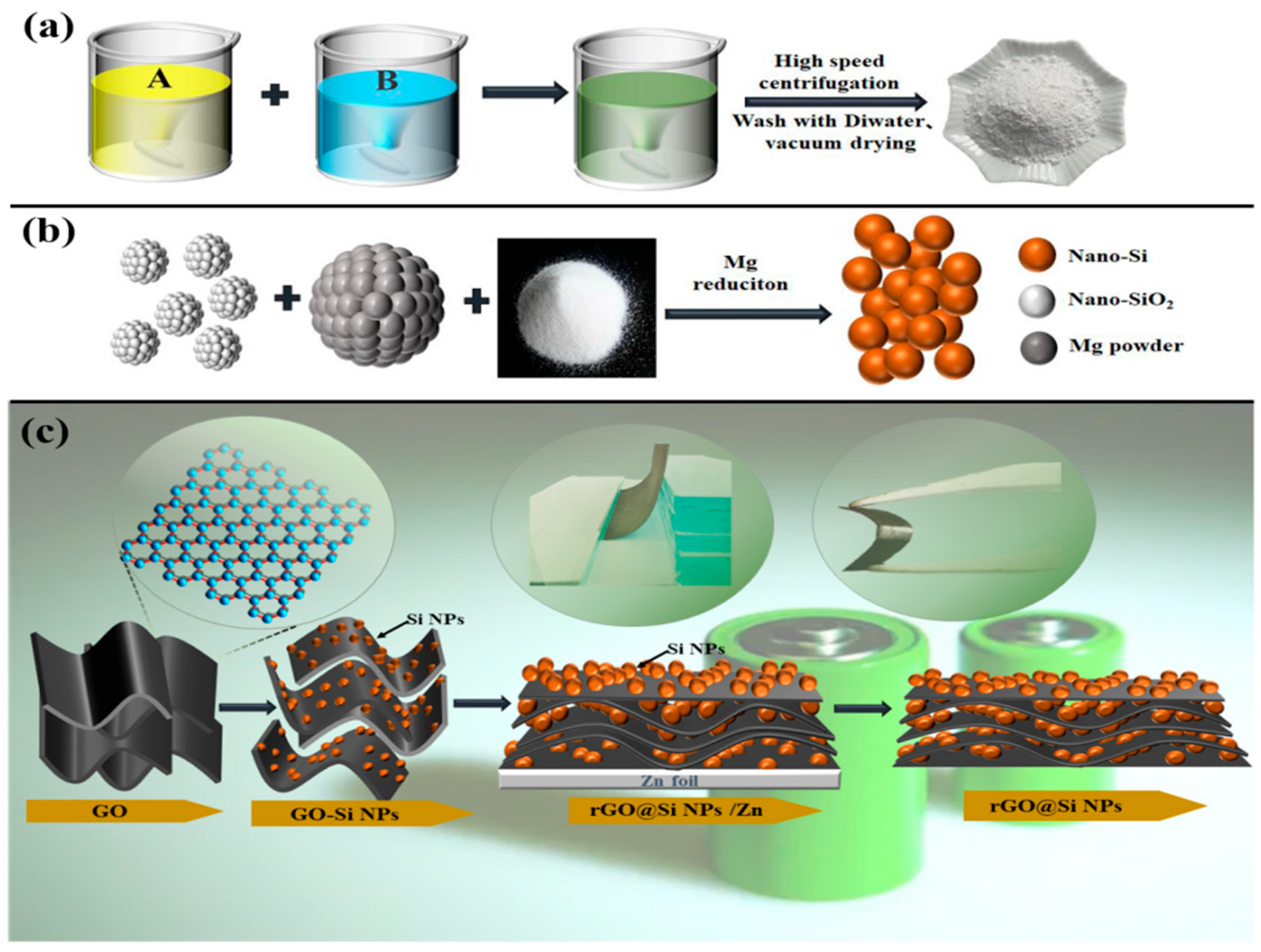
2.1. Preparation of Nano-SiO2

To prepare the nano-sized SiO2 material, first, 60 mL of anhydrous ethanol and 6 mL of ethyl silicate (TEOS, Wuhan Canos Technology Co., Ltd., Wuhan, China) solution were combined, stirred for 20 min, and labeled solution A. Next, 60 mL of anhydrous ethanol, 4 mL of deionized water (DI) and 10 mL of ammonia were combined and stirred for 20 min, and labeled solution B. Solution A and solution B were combined and stirred at a constant speed for 5 h in a 40 °C water bath. Then, 4 mL TEOS was added to the mixed solution which was stirred for 4 h. The solution was first washed several times with distilled water until the pH = 7, then several times with anhydrous ethanol (no separating funnel was used in the process), and dried in a vacuum at 60 °C for 12 h to obtain the precursor nano-SiO2 powder.

2.2. Preparation of Si NPs

A magnesium thermal reduction method was used to produce the Si NPs. First, 0.96 g of metal magnesium powder (Tianjin Beichen District Fangzheng Reagent Factory, Tianjin, China) and 0.6 g of the nano-SiO2 powder were mixed and this mixture was placed into the tube furnace in an Ar environment (Shanghai Lichen Instrument Technology Co., Ltd., Shanghai, China). The material was heated to 650 °C for 5 h at a heating rate of 5 °C min−1. Then continued to heat up to 850 °C at a rate of 5 °C min−1 and held for 4 h. The material was then cooled naturally under Ar. The resulting product was pickled with hydrochloric acid at a concentration of 2 mol L−1 for 5 h then washed with distilled water and anhydrous ethanol repeatedly. Si NPs was obtained via a vacuum drying of the as-prepared materials at 60 °C for 12 h.

2.3. Preparation of rGO@Si NPs Composite Films

The rGO@Si NPs composite films were prepared from a GO aqueous dispersion. A modified version of the Hummers process was used to produce the GO aqueous dispersion (10 mg mL−1) [37]. The high specific surface area of the GO sheets in the dispersion made it a suitable surfactant to disperse the nanostructured Si NPs. The procedure consisted of first, the precursor solution was prepared by adding 21 mL of the GO dispersion to 90 mg of the Si NPs which was magnetically stirred for 1–2 h at room temperature to ensure uniform dispersion of silicon nanoparticles. Next, a Zn plate was submerged in the aforementioned precursor solution and incubated in the solution at room temperature for one hour. The GO solutions containing Si NPs were reduced on the surface of the Zn plates which formed a film on the metal surface. This rGO@Si composite films film was then rinsed with DI water to remove substances that were physically adsorbed on the surface, and the composite membrane was submerged in DI water for 30 min to further eliminate the physically adsorbed complex. The composite film was then submerged in a solution of 0.5 mol L−1 H2SO4 and placed onto the surface of metallic Zn. The resulting composite film electrode material was peeled off the Zn. The rGO@Si NPs composite films were obtained by immersing the stripped composite membrane in a 0.5 mol L−1 H2SO4 solution to remove the Zn ions contained in the composite film. After further washing and freeze-drying for 24 h, a flexible rGO@Si NPs composite film was obtained and labeled rGO@Si NPs-1. These steps were repeated, and 0, 140, 210, and 315 mg Si NPs were added to 21 mL of GO dispersion to obtain composite film electrode materials, which were labeled rGO (0 mg), rGO@Si NPs-2(140 mg), rGO@Si NPs-3(210 mg), and rGO@Si NPs-4 (315 mg), respectively.

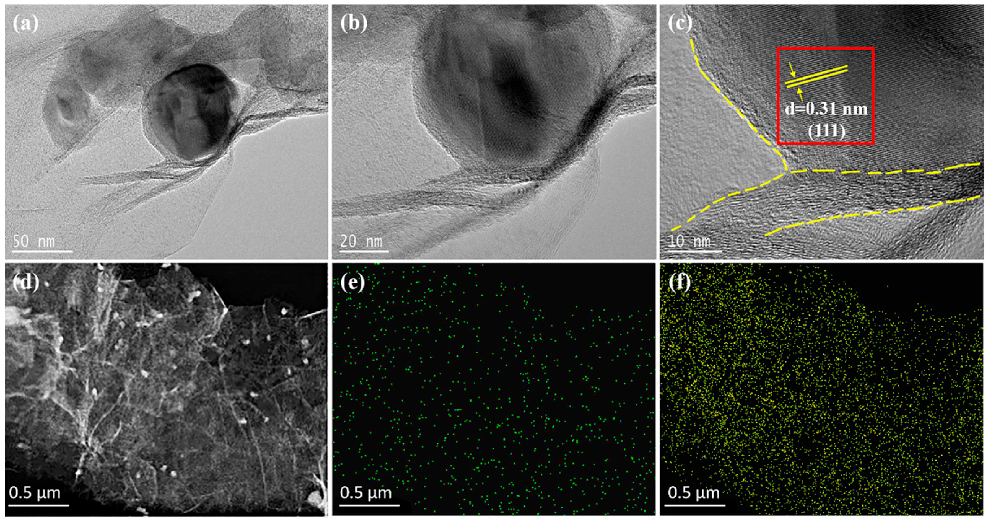
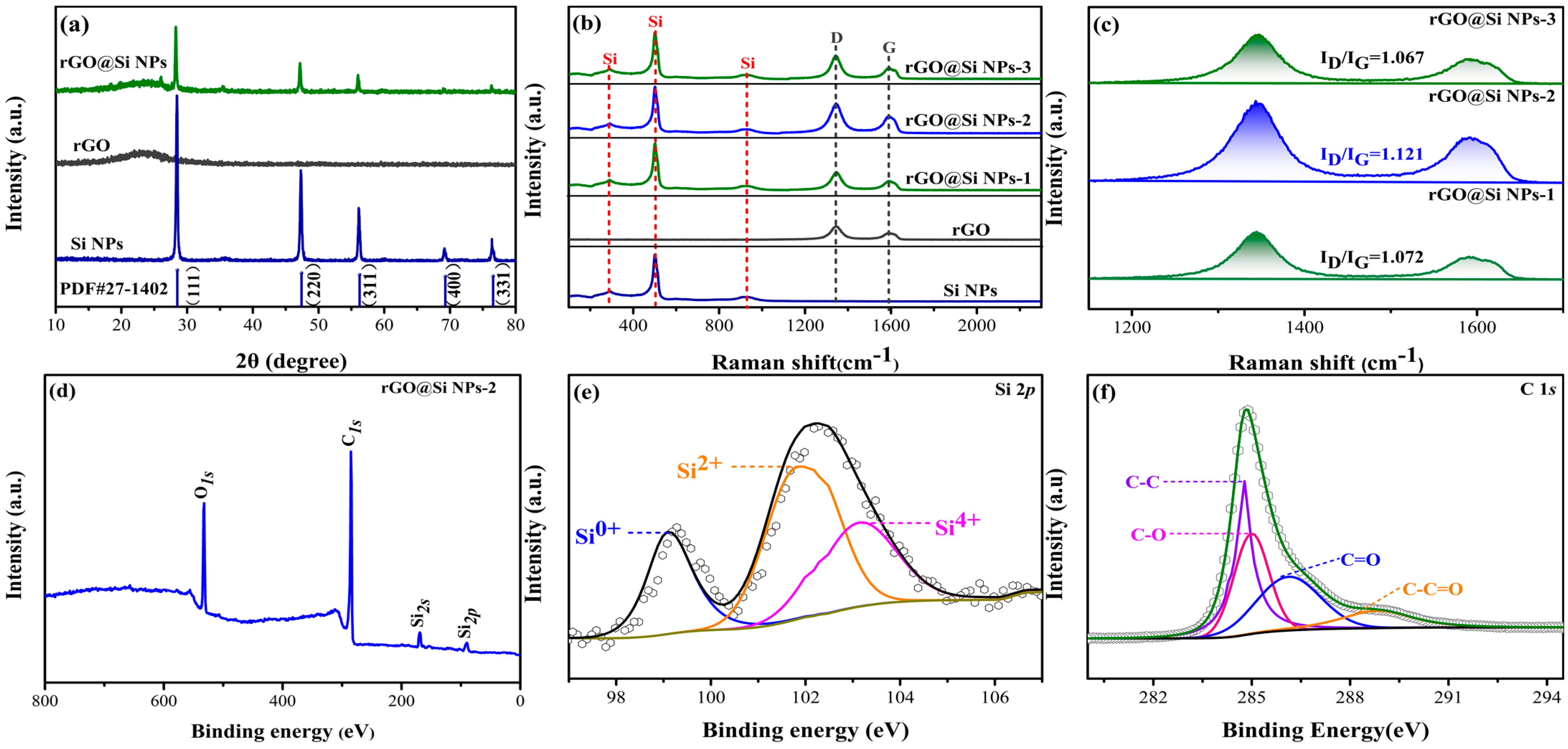
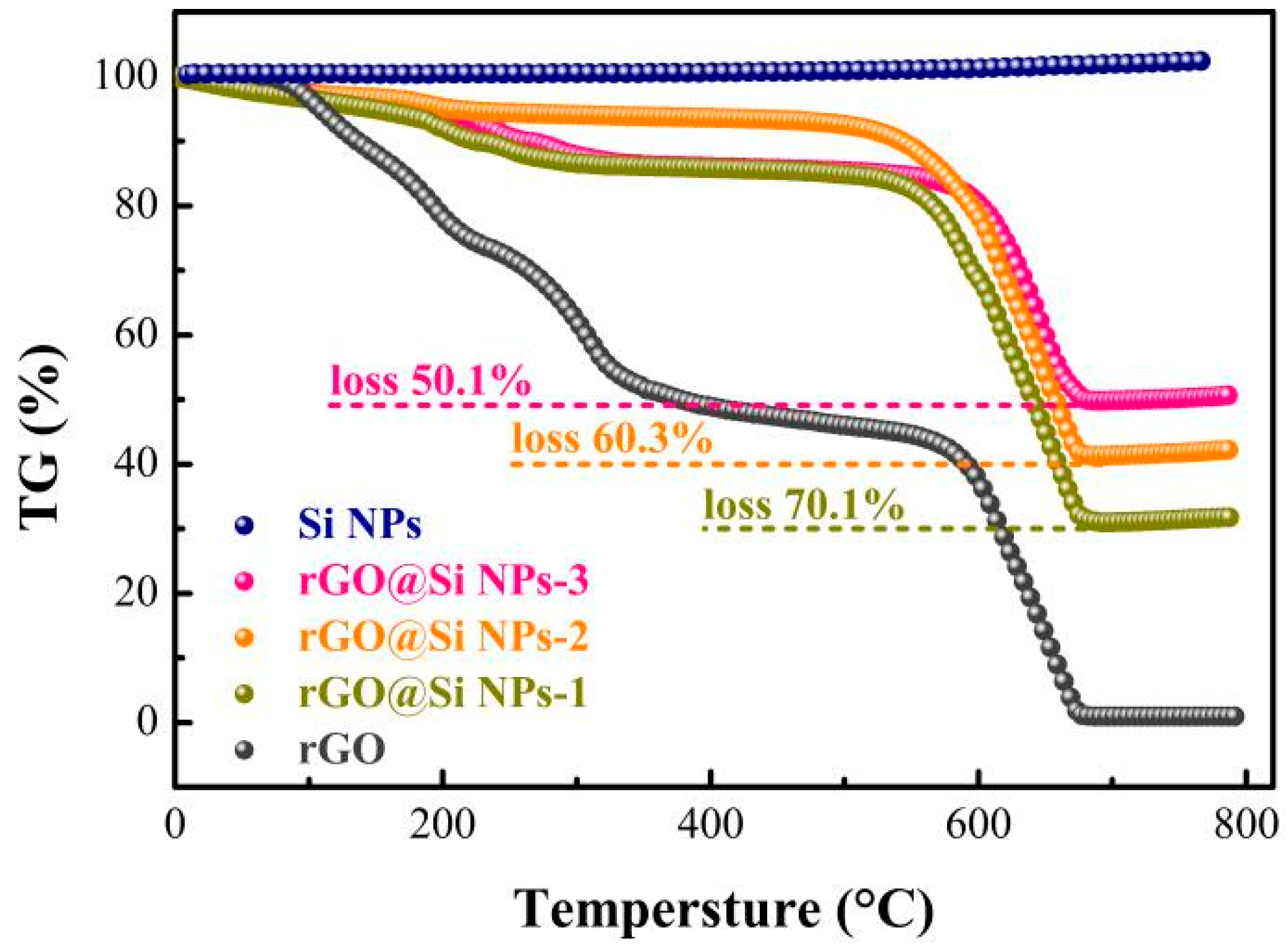
2.4. Materials Characterization

The cross-section morphology and microstructure of the composite film were characterized by field emission scanning electron microscopy (FE-SEM, JSM7500F, Shanghai Baihe Technologies Corporation, Shanghai, China); transmission electron microscope (TEM, JEM-2100F, JEOL Ltd., Tokyo, Japan). The crystal structure of the composite films was characterized using X-ray diffraction (XRD, D8 Advance, XI’AN Wilon Industrial Development INC., Xi’an, China). The elemental composition of the composite film surface was characterized using X-ray photoelectron spectroscopy (XPS, Thermo K-Alpha, Al Kα, Thermo Fisher Scientific (CHINA) Co., Ltd., Waltham, MA, USA). Thermogravimetric analysis (TG) was conducted on the films using a Netzsh TG 209 F1 (Netzsh Scientific Instruments TRADING Ltd., Shanghai, China), from 25 °C to 800 °C at a heating rate of 10 °C min−1 in an ambient air environment.

2.5. Electrochemical Measurements

Evaluation of Li+ storage performance of the composite films was conducted using coin-type half cells (CR2032, Guangdong Canrd New Energy Technology Co., Ltd., Guangdong, China). The rGO@Si NPs composite films and pure-Si were used as the working electrodes, respectively. A lithium foil was used as the counter electrode. 1 M LiPF6 in ethylene carbonate (EC) and diethyl carbonate (DEC) (1:1 in volume ratio) was used as the electrolyte. A Celgard 2400 film was used as the separator. A CT 2001A (LAND, Wuhan Bateri Technology Co., Ltd., Wuhan, China) automatic battery testing system was employed to assess the cycle performance and rate capabilities of the coin cells over a voltage range of 0.01–2.0 V (vs. Li+/Li) at ambient temperature. A CHI760E electrochemical workstation ((Shanghai Chenhua Instrument Co., Ltd., Shanghai, China) was used to conduct cyclic voltammetry (CV) tests at a scanning rate of 0.2 mV s−1 in the voltage window range of 0.01–1.5 V (against Li/Li+). A CHI660E electrochemical workstation (Shanghai Chenhua Instrument Co., Ltd., Shanghai, China), was used to conduct electrochemical impedance spectra (EIS) testing on the coin cells from 10−2–105 Hz. The temperature was maintained at 26 °C for the duration of the measurement.

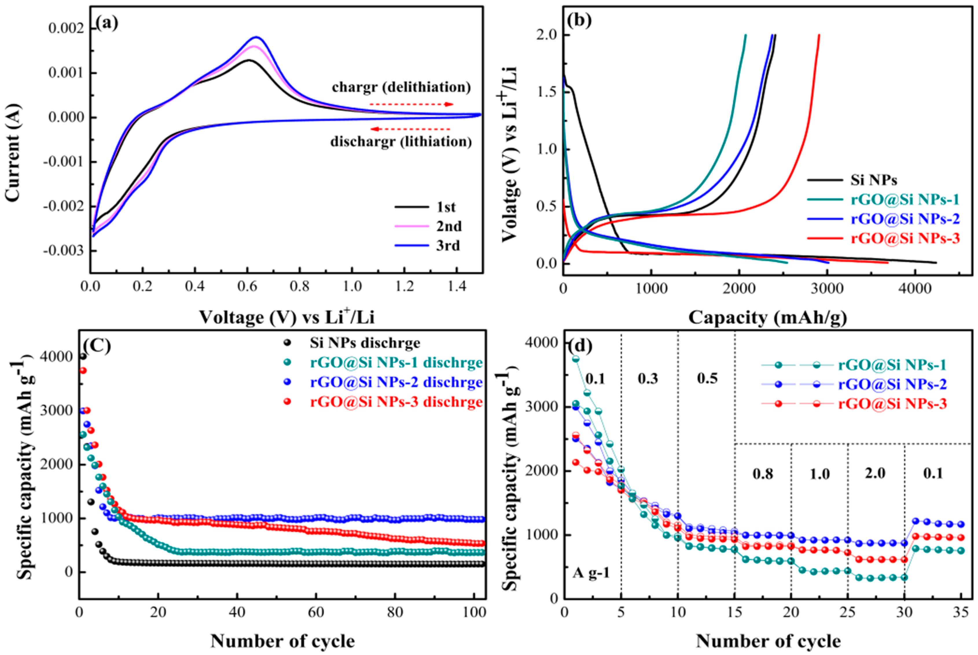
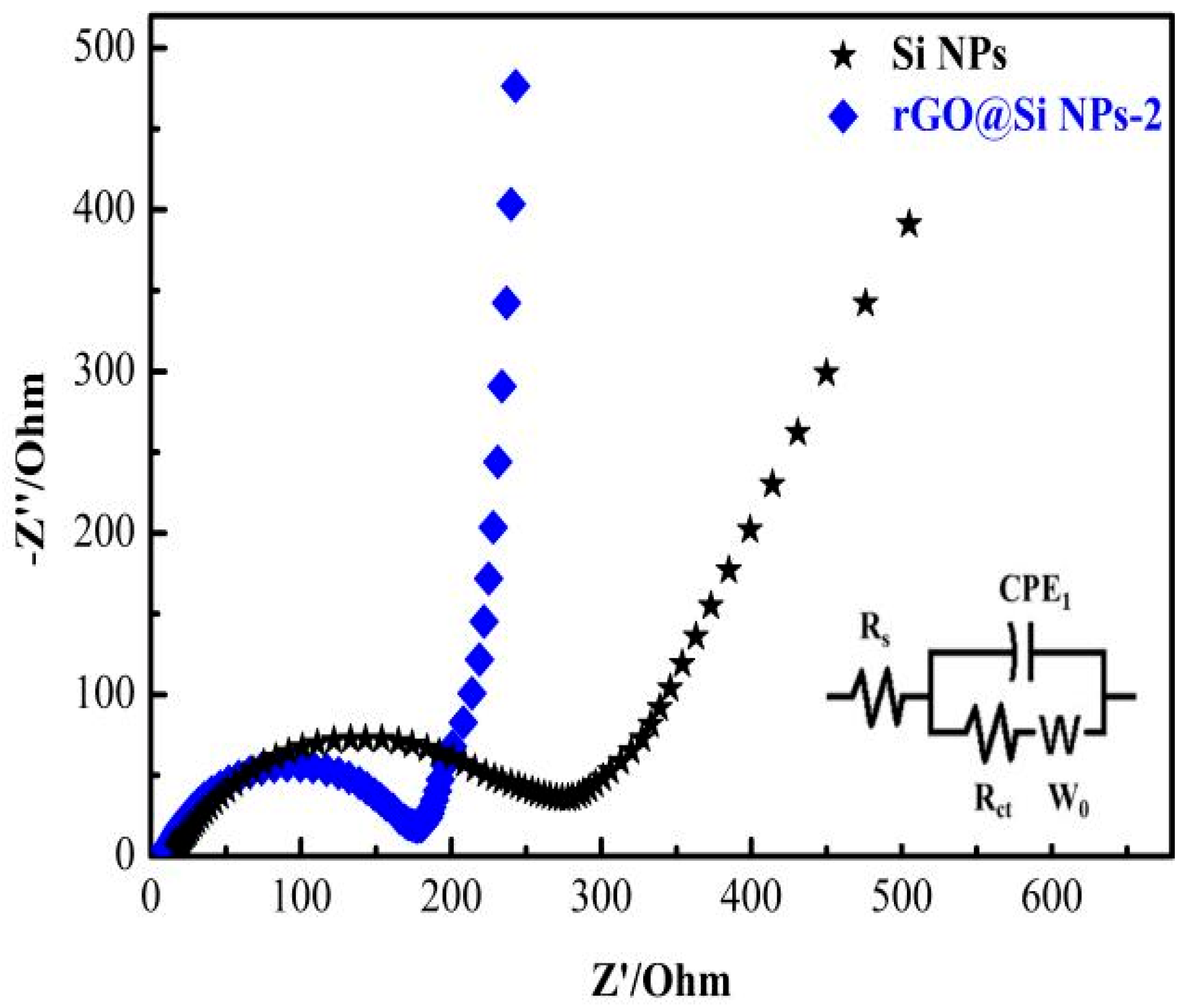
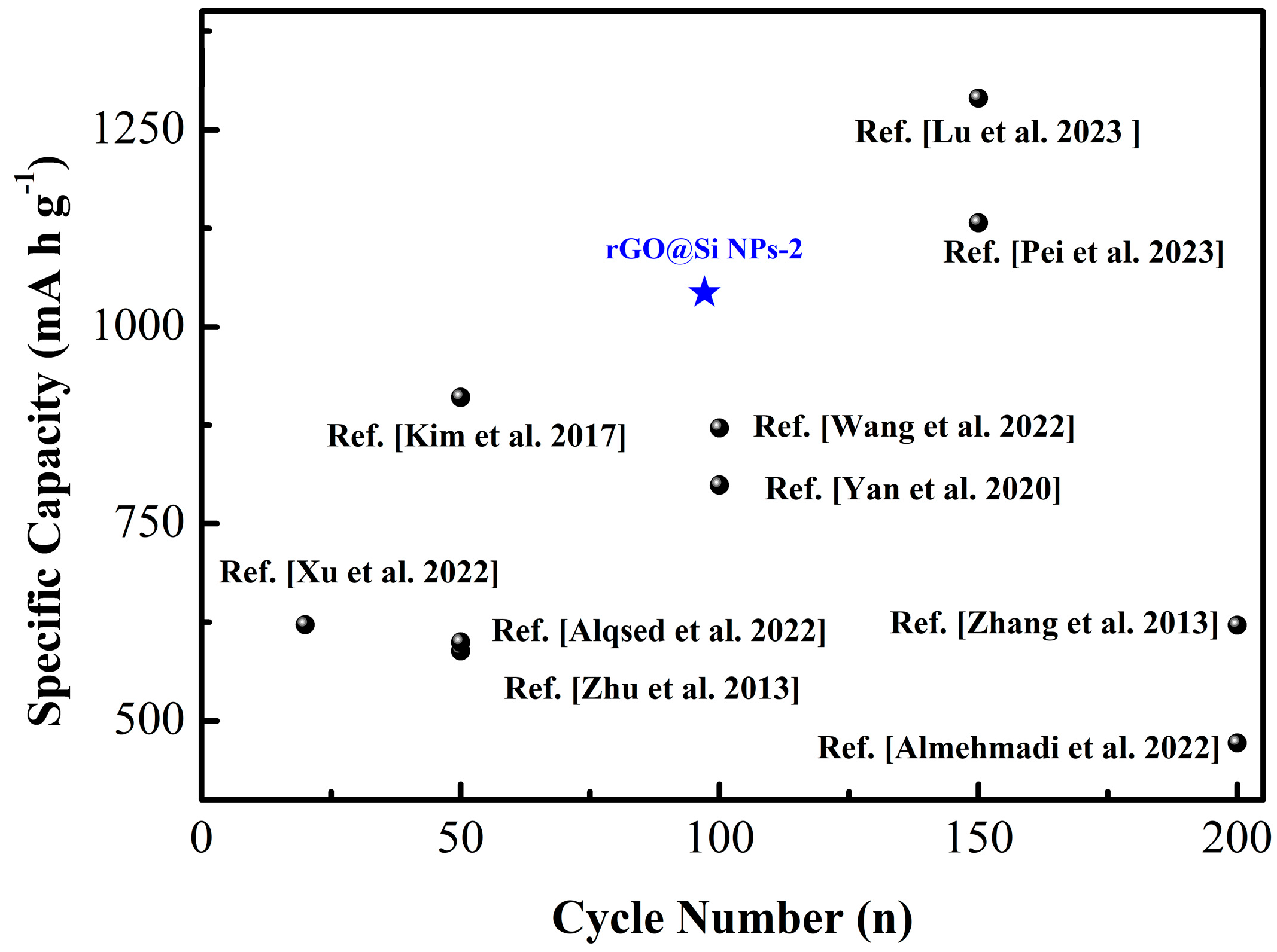
3. Results and Discussion

The synthesis process used to produce the nano-SiO2, Si NPs, and self-supporting rGO@Si NPs composite films is shown in Figure 1a–c.
It was found that the mechanical behavior of the rGO@Si NPs composite membrane made them very flexible so they could be bent and even doubled over with no crevices produced (the illustration in Figure 1c). The Si NPs were grown in situ on the GO sheets, ensuring good physical contact between the two. The additional in-situ growth of Si NPs was limited because there were fewer anchoring Si atoms in the Si-O groups on the surface of GO sheets. The Zn foil reduced the GO sheet because the rGO/GO had a higher reduction potential than Zn/Zn2+ (0.76 V versus SHE) at pH = 4 (0.4 V against SHE). However, too many Si NPs prevented the GO sheet from self-assembling into a complete composite film, which resulted in the production of cracks in the film [39,40]. Figure 2 illustrates the micromorphology of nano-SiO2 (a) and Si NPs (b), as well as the cross-section of the rGO film (c), rGO@Si NPs-1 (d), -2 (e), and -3 (f). The preparation of rGO@Si NPs-4 failed, as evidenced by Figure 2g where it can be seen that the film was completely broken up. The GO sheet layer produced on the Zn foil’s surface easily received electrons from the Zn foil during the reduction process. Because the GO sheet was negative, the Zn2+ ions from the surface of the Zn foil were attracted by the GO sheet [38]. This chemically reduced the GO sheets and an incredibly thin layer of rGO developed and adhered to the Zn plate’s surface.
Thereafter, electrons were transferred from inside the Zn foil through the layered rGO to the outer GO sheet causing the rGO sheet and the Si NPs to weakly electrostatically repel each other. When the bonding interaction between them was greater than the static repulsive force between the rGO sheet and Si NPs (for example the π–π interaction and hydrophobic), both the rGO sheets and Si NPs cross-linked layer-by-layer to produce the rGO@Si NPs nanostructured composite film with cross-linked porous layers [41].
Figure 2a shows that the grain sizes of nano-SiO2 prepared by a solution gel method were evenly distributed, and the particles had a diameter that varied between 600 and 700 nm. The morphology of Si NPs further obtained by the magnesium thermal reduction method is shown in Figure 2b, where it appeared that there was a small amount of Si NPs particle aggregation. However, the spherical particles were between 40 and 70 nm in size. Figure 2c shows the multi-layer cross-linked pore structure of the cross-sectional view of rGO without nano-silicon particles. The continuous cross-linked structure formed in the rGO@Si NPs composite film ensured fast electron transport by successfully avoiding stacking rGO sheets, and this occurred throughout the sheet network structure. Figure 2d shows that fewer, uneven Si NPs adhered between rGO layers when the Si NP concentration was 90 mg. As seen in Figure 2e, more Si NPs were embedded between the rGO layers when the Si NP concentration was increased to 140 mg. The Si NPs were also equally distributed over the surface of the rGO sheets. When the amount of Si NPs was increased to 210 mg, particle agglomeration prevented viewing of the lamellar structure of rGO, as shown in Figure 2f.
The TEM images of the materials in Figure 3a,b clearly reveal that the Si NPs were embedded in the 2D lamellar structure of rGO. In addition, the TEM images of the selected areas and the corresponding element mapping showed that the Si NPs were evenly embedded in the rGO lamellar structure. Combining this information with the SEM images it appeared that the structure of lamellar graphene was evenly coated. Therefore, the even coating of rGO improved the conductivity of the Si NPs. Furthermore, from the HRTEM images shown in Figure 3c, the (111) crystal surface of silicon can be clearly seen, and the lattice spacing was calculated to be 0.31 nm. This lamellar structure possessed a degree of toughness, which could withstand large volume changes of Si during cycling to enhance the cycle stability.
In addition to the characterization of the appearance of the sample, the composition, content, and valence state of the atoms contained in the sample were analyzed. The XRD patterns of the prepared Si NPs, rGO, and rGO@Si NPs composites are shown in Figure 4a. The characteristic diffraction peaks of the rGO@Si NPs sample were located at 28.3°, 47.0°, 56.2°, 69.3°, and 76.5° (PDF#27-1402), which demonstrated that the Si crystal structure was retained during the production process. In addition, the XRD results of rGO show that there is an obvious envelope peak at about 24°, which corresponded to the (002) crystal face of graphite, which also suggested that the prepared rGO was composed of an indeterminate type of carbon [42]. The presence of this packet peak can also be observed at the same position (2θ ≈ 24°) in the images of the rGO@Si NPs composites, which suggests the effective introduction of carbon (rGO) and the successful preparation of the composites.
Raman spectroscopy was conducted on the experimental materials to study the structural aspects of the Si NPs, rGO, and rGO@Si NPs composite films, and the results are shown in Figure 4b. Peaks at 290, 513, and 926 cm−1 are indicative of the pure Si vibrational band and its resonances [43]. The rGO@Si NPs composite had two different peaks. The vibration peaks at 1354 cm−1 and 1588 cm−1 corresponded to D-band and G-band, respectively. The D-band peak corresponds to the defect and disorder degree of the carbon structure, while the G-band corresponds to the sp2 bond carbon atom in the graphite structure [44]. As illustrated in Figure 4, the basic amorphous structure of the rGO sheet coated on Si NPs was determined by the peak ratio of D peak intensity and G peak intensity. These values, as shown in Figure 4c, for the rGO@Si NPs-1, -2, and -3, were 1.072, 1.121, and 1.067 respectively, indicating that a for all these samples, a sheet of amorphous rGO was coated on the Si NPs.
The elemental composition of rGO@Si NPs composite was further analyzed using XPS tests. As illustrated in Figure 4, the survey clearly showed the Si, O, and C peak locations (d). The silicon oxide species generated during sample preparation and testing were responsible for the O [45]. Figure 4e shows the high-resolution Si 2p XPS spectra of rGO@Si NPs composite, which can be deconvoluted into Si0+ (99.08 eV), Si2+ (101.8 eV), and Si4+ (103.1 eV), respectively [46]. The peak area of Si2+ and Si4+ is larger than that of Si0+ because of the surface oxidation of Si NPs [47]. According to Figure 4f, which corresponds to the C 1s fitting, the groups C-C, C-O, C=O, and C-C=O were present with binding energies at 284.7, 284.9, 286.1, and 285.5 eV [46].
The mass percentages of the Si NPs, rGO, rGO@Si NPs-1, -2, and -3 were evaluated by TG testing (Figure 5). As shown, there was a significant mass decrease in the range of 500 °C to 650 °C which was attributed to the decomposition of rGO because the Si content did not change substantially with the temperature [48]. After 700 °C, the curve had a slight upward trend due to the progressive oxidation of the Si NPs [49]. Based on this analysis the mass of C in rGO@Si NPs-1, -2, and -3 was around 70.1, 60.3, and 50.1 wt.%, respectively. Therefore, the mass of Si in rGO@Si NPs-1, -2, and -3 was about 29.9, 39.7, and 49.9 wt.%; this is in agreement with expectations, which can also be clearly seen in the SEM in Figure 4d–f.
To assess their electrochemical performance, all the experimental composites were used to fabricate half-cells in a glove box and tested for their electrochemical characteristics. Figure 6 shows the electrochemical performance of the Si NPs, rGO@Si NPs-1, -2, and -3. The first three CV cycles of the rGO@Si NPs-2 composite film electrode’s CV curves between 0.01 and 1.5 V at a scan rate of 0.2 mV s−1 are shown in Figure 6a. The two peaks for the lithiation process are visible in these curves. An SEI film was formed on the surface of the composite, which led to the initial irreversible capacity, associated with the reduction peak at 0.3 V. The peak at 0.1 V corresponded to the lithium reaction (Li → LixSi). The corresponding oxidation peak at 0.6 V was related to the transition from high lithiated Si to less lithiated Si and the delithium reaction (LixSi → Li) of Si [50].
To illustrate the electrochemical performance more comprehensively, the first discharge and charge pattern of Si NPs, rGO@Si NPs-1, -2, and -3 electrodes at a current density of 200 mA g−1, with the voltage range 0.01–2 V are shown in Figure 6b. The first cycle discharge and charge capacities of Si NPs, rGO@Si NPs-1, rGO@Si NPs-2, and rGO@Si NPs-3 electrode cells were 4237/2410, 2543/2073, 3015/2375, and 3687/2908 mA h g−1 with coulombic efficiencies (CE) of 56.9%, 78.8%, 78.7%, and 81.5%. The low CE was attributed to the formation of the SEI film during the process of circulation [43,51]. The rGO@Si NPs composite film exhibited a clear voltage plateau around 0.1 V, which corresponded to the Li-Si alloy formation during the first discharge. The CE of rGO@Si NPs composite films were considerably higher than those of the Si NPs. This result showed that the composite with lamellar rGO can buffer the volume expansion of Si NPs during charge and discharge.
The electrochemical performance measurements of the Si NPs, rGO@Si NPs-1, rGO@Si NPs-2, and rGO@Si NPs-3 were obtained, as shown in Figure 6. As shown, the stability of the Si NPs was very poor, and an attenuation was evident, which dropped to almost zero capacity within 20 cycles, as has been previously reported [52]. However, during our tests, the rGO@Si NPs-2 composite membrane electrode exhibited excellent capacity retention. The discharge capacity was maintained at 1003.4 mA h g−1 even at a current density of 200 mA g−1, and it remained steady after 100 cycles. The electrochemical performance of the other two materials, which contained varying amounts of silicon, was noticeably worse than rGO@Si NPs-2. Despite the low Si content in the rGO@Si NPs-1 composite film, it also exhibited good cycling stability, except for a low capacity, with a value of 365.2 mA h g−1 after 100 cycles. The small proportion of Si NPs and uneven distribution between rGO sheets produced a low capacity as shown in Figure 2d. Nevertheless, the initial capacity of rGO@Si NPs-3 composite film was high but declined throughout the test, with a value of 534.2 mA h g−1 after 100 cycles, due to the high content and uneven distribution of Si NPs, and some agglomeration, as shown in Figure 2f. In addition, the reversible capacity was reduced to 600 mA h g−1 after 30 cycles compared to the previously designed porous C/Si composite [53]. It is due to the use of a graphene layered cross-linked structure to buffer the large bulk effect of the silicon nanoparticles during cycling due to the embedding and detachment of lithium ions, thus improving the charge migration rate and ion transport rate, which in turn improves the reversible capacity of the composite.
The multiplier performance is a key factor in the application of LIBs. Figure 6d shows that the average discharge capacity of all samples such as rGO@Si NPs-1 decreased when the current density rose from 100 mA g−1 to 2000 mA g−1. The average discharge capacity of rGO@Si NPs-2 was still 876.4 mA h g−1. However, the average discharge capacities of rGO@Si NPs-1 and rGO@Si NPs-3 were only 334.2 and 653.6 mA h g−1, respectively, even at a high current density of 2000 mA g−1. Additionally, when the current density was returned to 0.1 mA g−1, the discharge capacities of rGO@Si NPs-1, rGO@Si NPs-2, and rGO@Si NPs-3 showed recovery and remained steady. However, the rGO@Si NPs-2 recovery was better at 1188.38 mA h g−1, a clear advantage. The performance of rGO@Si NPs-1 and NPs-3 was worse, recovering at only 772.1 and 970.74 mA h g−1, respectively.
Figure 7 is the impedance curve of the sample before the cycle, and the equivalent circuit is shown in Figure 7 (illustrated). Rct represents the charge transfer resistance corresponding to the semicircle in the high frequency region, and W0 (Warburg impedance) is related to the diffusion resistance of lithium ion in electrolyte and active material, corresponding to the straight line in the low-frequency region. In addition, Rs represents the intersection of the corresponding curve and the real axis of the internal resistance, mainly related to the electrolyte and electrode material [54,55]. The excellent conductivity of graphene resulted in a significant decrease in the Rct of the composites (177 Ω). The cross-linked layered structure of graphene in the composite also provides ample channels for transporting lithium ions, resulting in a much smaller Li+ diffusion resistance (W0) compared to Si NPs, which can be clearly seen in the straight lines in the low-frequency region. In addition, the Rs of the rGO@Si NPs-2 (8.75 Ω) was significantly lower than that of Si NPs (18.2 Ω), indicating that the resistance of the composite itself was improved. This improvement can be attributed to the exceptional conductivity of the two-dimensional lamellar graphene and the effective combination between the two materials [56].
In this regard, rGO@Si NPs-2 had the best electrochemical performance for the following reasons: first, compared with rGO@Si NPs-3, the Si NPs were evenly distributed in the rGO sheets, and no agglomeration was observed. Second, compared to rGO@Si NPs-1, the content of Si NPs was higher, so the available capacity was higher than rGO@Si NPs-1. Third, because graphene had good conductivity, its addition improved the ion diffusion of the composite film. Last but not least, the special 2D lamellar structure of graphene had was strong and tough which effectively alleviated the large expansion of Si NPs during the charge and discharge process. A comparison with other Si/C anode materials is shown in Figure 8, the rGO@Si NPs composite film electrode materials exhibit excellent cycling stability [32,57,58,59,60,61,62,63,64,65].

4. Conclusions

In summary, this study has successfully prepared rGO@Si NPs composite film by metal reduction film formation method and demonstrated the excellent electrochemical performance of this composite film as an electrode material in Li-ion batteries. Although the specific capacity is slightly lower than some of the currently studied Si/C composites, the composite film has a flexible self-supporting structure and good mechanical properties that do not break under a certain degree of bending, while eliminating the need to add any binder and use a collector fluid, reducing production costs and simplifying the process. By adjusting the proportion of Si NPs, we found that the composite film has the best electrochemical properties when the Si NPs are 40%. The reversible specific capacity reached 876 mA h g−1 at the current density of 2000 mA g−1, while still providing a discharge capacity of 1003.4 mA h g−1 after 100 cycles at a current density of 200 mA g−1. The application of flexible silicon-based anode materials in LIBs has not yet been extensively investigated, so we will continue to improve the process to enhance its electrochemical performance. In summary, the flexible silicon-based composite electrode material reported in this project has a broad development prospect.

Author Contributions

Methodology, Z.C.; Software, T.B. and H.L.; Formal analysis, Y.C.; Investigation, X.Z.; Resources, X.Z.; Data curation, Z.C. and Q.W.; Writing original draft, Z.C.; Writing review & editing, J.C.; Visualization, J.C.; Supervision, J.C.; Project administration, W.S.; Funding acquisition, B.Z. and W.S. All authors have read and agreed to the published version of the manuscript.

Funding

This work was supported by the National Natural Science Foundation of China (21706148), the Natural Science Foundation of Shandong Province (ZR2020ME041, ZR2022QB173), the Joint Zibo-SDUT Fund (2019ZBXC358), and the Foundation of State Key Laboratory of Biobased Material and Green Papermaking, Qilu University of Technology, Shandong Academy of Sciences (KF2019-06).

Data Availability Statement

Data underlying the results presented in this paper are not publicly available at this time but may be obtained from the authors upon reasonable request.

Conflicts of Interest

The authors declare no conflict of interest.

References

  1. Armand, M.; Tarascon, J. Building better batteries. Nature 2008, 451, 652–657. [Google Scholar] [CrossRef]
  2. Zhao, Y.; Ding, Y.; Li, Y.T.; Peng, L.L.; Byon, H.R.; Goodenough, J.B.; Yu, G.H. A chemistry and material perspective on lithium redox flow batteries towards high-density electrical energy storage. Chem. Soc. Rev. 2015, 44, 7968. [Google Scholar] [CrossRef] [PubMed] [Green Version]
  3. Ji, X.L.; Lee, K.T.; Nazar, L.F. A highly ordered nanostructured carbon–sulphur cathode for lithium–sulphur batteries. Nat. Mater. 2009, 8, 500–506. [Google Scholar] [CrossRef]
  4. Nitta, N.; Yushin, G. High-Capacity Anode Materials for Lithium-Ion Batteries: Choice of Elements and Structures for Active Particles. Part. Part. Syst. Charact. 2014, 31, 317–336. [Google Scholar] [CrossRef]
  5. Kang, B.; Ceder, G. Battery materials for ultrafast chargingand discharging. Nat. Lett. 2009, 458, 190–193. [Google Scholar] [CrossRef] [PubMed]
  6. Saw, L.H.; Ye, Y.; Tay, A.A.O. Integration issues of lithium-ion battery into electric vehicles battery pack. J. Clean. Prod. 2016, 113, 1032–1045. [Google Scholar] [CrossRef]
  7. Liu, X.L.; Gao, Y.F.; Jin, R.H.; Luo, H.J.; Peng, P.; Liu, Y. Scalable synthesis of Si nanostructures by low-temperature magnesiothermic reduction of silica for application in lithium ion batteries. Nano Energy 2014, 4, 31–38. [Google Scholar] [CrossRef]
  8. Wu, H.; Cui, Y. Designing nanostructured Si anodes for high energy lithium ion batteries. Nano Today 2012, 7, 414–429. [Google Scholar] [CrossRef]
  9. Nitta, N.; Wu, F.; Lee, J.T.; Yushin, G. Li-ion battery materials: Present and future. Mater. Today 2015, 18, 252–264. [Google Scholar] [CrossRef]
  10. Kasavajjula, U.; Wang, C.; Appleby, A.J. Nano-and bulk-silicon-based insertion anodes for lithium-ion secondary cells. J. Power Sources 2007, 163, 1003–1039. [Google Scholar] [CrossRef]
  11. Boukamp, B.A.; Lesh, G.C.; Huggins, R.A. All Solid Lithium Electrodes with Mixed Conductor Matrix. J. Eletrochem. Soc. 1981, 128, 725. [Google Scholar] [CrossRef]
  12. He, Y.; Yu, X.; Wang, Y.; Li, H.; Huang, X. Alumina-coated patterned amorphous silicon as the anode for a lithium-ion battery with high coulombic efficiency. Adv. Mater. 2011, 23, 4938–4941. [Google Scholar] [CrossRef] [PubMed]
  13. Aghajamali, M.; Xie, H.; Javadi, M.; Kalisvaart, W.P.; Buriak, J.M.; Veinot, J.G.C. Size and Surface Effects of Silicon Nanocrystals in Graphene Aerogel Composite Anodes for Lithium Ion Batteries. Chem. Mater. 2018, 30, 7782–7792. [Google Scholar] [CrossRef]
  14. Liu, L.; Lyu, J.; Li, T.; Zhao, T. Well-constructed silicon-based materials as high-performance lithium-ion battery anodes. Nanoscale 2016, 8, 701–722. [Google Scholar] [CrossRef] [PubMed]
  15. Szczech, J.R.; Jin, S. Nanostructured silicon for high capacity lithium battery anodes. Energy Environ. Sci. 2011, 4, 56. [Google Scholar] [CrossRef]
  16. Lee, S.W.; McDowell, M.T.; Choi, J.W.; Cui, Y. Anomalous Shape Changes of Silicon Nanopillars by Electrochemical Lithiation. Nano Lett. 2011, 11, 3034–3039. [Google Scholar] [CrossRef]
  17. Bordes, A.; Vito, E.D.; Haon, C.; Boulineau, A.; Montani, A.; Marcus, P. Multiscale Investigation of Silicon Anode Li Insertion Mechanisms by Time-of-Flight Secondary Ion Mass Spectrometer Imaging Performed on an In Situ Focused Ion Beam Cross Section. Chem. Mater. 2016, 28, 1566–1573. [Google Scholar] [CrossRef]
  18. Dong, H.; Wang, J.; Ding, H.; Zong, F.F.; Wang, P.; Song, R.; Zhang, N.S.; Cui, X.L.; Cui, X.C.; Li, S.Y. Exploring the practical applications of silicon anodes: A review of silicon-based composites for lithium-ion batteries. Ionics 2022, 28, 3057–3077. [Google Scholar] [CrossRef]
  19. Johnson, D.C.; Mosby, J.M.; Riha, S.C.; Prieto, A.L. Synthesis of copper silicide nanocrystallites embedded in silicon nanowires for enhanced transport properties. J. Mater. Chem. 2010, 20, 1993–1998. [Google Scholar] [CrossRef]
  20. Laïk, B.; Ung, D.; Caillard, A.; Cojocaru, C.S.; Pribat, D.; Pereira-Ramos, J.P. An electrochemical and structural investigation of silicon nanowires as negative electrode for Li-ion batteries. J. Solid State Electrochem. 2010, 14, 1835–1839. [Google Scholar] [CrossRef]
  21. Chen, H.; Xiao, Y.; Wang, L.; Yang, Y. Silicon nanowires coated with copper layer as anode materials for lithium-ion batteries. J. Power Sources 2011, 196, 6657–6662. [Google Scholar] [CrossRef]
  22. Hu, L.; Wu, H.; Hong, S.S.; Cui, L.; McDonough, J.R.; Bohy, S.; Cui, Y. Si nanoparticle-decorated Si nanowire networks for Li-ion battery anodes. Chem. Commun. 2011, 47, 367–369. [Google Scholar] [CrossRef] [PubMed]
  23. Lee, W.J.; Park, M.H.; Wang, Y.; Lee, J.Y.; Cho, J. Nanoscale Si coating on the pore walls of SnO2 nanotube anode for Li rechargeable batteries. Chem. Commun. 2010, 46, 622–624. [Google Scholar] [CrossRef] [Green Version]
  24. Song, T.; Xia, J.; Lee, J.H.; Lee, D.H.; Kwon, M.S.; Choi, J.M.; Wu, J.; Doo, S.K.; Chang, H.; Park, W.I.; et al. Arrays of sealed silicon nanotubes as anodes for lithium ion batteries. Nano Lett. 2010, 10, 1710–1716. [Google Scholar] [CrossRef] [PubMed]
  25. Hu, X.; Jin, Y.; Zhu, B.; Liu, Z.; Xu, D.; Guan, Y.; Sun, M.; Liu, F. Tuning density of Si nanoparticles on graphene sheets in graphene-Si aerogels for stable lithium ion batteries. J. Colloid Interface Sci. 2018, 532, 738–745. [Google Scholar] [CrossRef] [PubMed]
  26. Chang, P.; Liu, X.; Zhao, Q.; Huang, Y.; Huang, Y.; Hu, X. Constructing Three-Dimensional Honeycombed Graphene/Silicon Skeletons for High-Performance Li-Ion Batteries. ACS Appl. Mater. Interfaces 2017, 9, 31879–31886. [Google Scholar] [CrossRef]
  27. Fang, G.; Deng, X.; Zou, J.; Zeng, X. Amorphous/ordered dual carbon coated silicon nanoparticles as anode to enhance cycle performance in lithium ion batteries. Electrochim. Acta 2019, 295, 498–506. [Google Scholar] [CrossRef]
  28. Wang, W.; Gu, L.; Qian, H.; Zhao, M.; Ding, X.; Peng, X.; Sha, J.; Wang, Y. Carbon-coated silicon nanotube arrays on carbon cloth as a hybrid anode for lithium-ion batteries. J. Power Sources 2016, 307, 410–415. [Google Scholar] [CrossRef]
  29. Gong, X.H.; Zheng, Y.B.; Zheng, J.; Cao, S.P.; Wen, H.; Lin, B.P.; Sun, Y.M. Yolk-shell silicon/carbon composites prepared from aluminum-silicon alloy as anode materials for lithium-ion batteries. Ionics 2021, 27, 1939–1948. [Google Scholar] [CrossRef]
  30. Ji, L.W.; Zhang, X.W. Fabrication of porous carbon/Si composite nanofibers as high-capacity battery electrodes. Electrochem. Commun. 2009, 6, 1146–1149. [Google Scholar] [CrossRef]
  31. Gao, R.S.; Tang, J.; Zhang, K.; Ozawa, K.; Qin, L.C. A sandwich-like silicon–carbon composite prepared by surface-polymerization for rapid lithium-ion storage. Nano Energy 2020, 78, 105341. [Google Scholar] [CrossRef]
  32. Lu, Y.H.; Ye, Z.T.; Zhao, Y.T.; Li, Q.; He, M.Y.; Bai, C.C.; Wang, X.T.; Han, Y.L.; Wan, X.C.; Zhang, S.L.; et al. Graphene supported double-layer carbon encapsulated silicon for high-performance lithium-ion battery anode materials. Carbon 2023, 201, 962–971. [Google Scholar] [CrossRef]
  33. Lee, J.K.; Smith, K.B.; Hayner, C.M.; Kung, H.H. Silicon nanoparticles-graphene paper composites for Li ion battery anodes. Chem. Commun. 2010, 46, 2025–2027. [Google Scholar] [CrossRef] [PubMed]
  34. Khan, M.; Kuniyil, M.; Shaik, M.R.; Adil, S.F.; Warthan, A.A.; Alkhahlan, H.A.; Tremel, W.; Tahir, M.N.; Siddiqui, M.R.H. Plant extract mediated eco-friendly synthesis of Pd@graphene nanocatalyst: An efficient and reusable catalyst for the Suzuki-Miyaura coupling. Catalysts 2017, 7, 20. [Google Scholar] [CrossRef] [Green Version]
  35. Khan, M.; Al-Marri, A.H.; Mohri, N.; Adil, S.F.; Al-Warthan, A.; Siddiqui, M.R.H.; Alkhathlan, H.Z.; Berger, R.; Tremel, W.; Tahir, M.N. Pulicaria glutinosa plant extract: A green and eco-friendly reducing agent for the preparation of highly reduced graphene oxide. RSC Adv. 2014, 4, 24119. [Google Scholar] [CrossRef]
  36. Nzabahimana, J.; Chang, P.; Hu, X. Porous carbon-coated ball-milled silicon as high-performance anodes for lithium-ion batteries. J. Mater. Sci. 2018, 54, 4798–4810. [Google Scholar] [CrossRef]
  37. Fan, X.; Wang, Z.; Cai, T.; Yang, Y.; Wu, H.; Cao, S.; Yang, Z.; Zhang, W. An integrated highly stable anode enabled by carbon nanotube-reinforced all-carbon binder for enhanced performance in lithium-ion battery. Carbon 2021, 182, 749–757. [Google Scholar] [CrossRef]
  38. Cao, J.; Chen, C.; Zhao, Q.; Zhang, N.; Lu, Q.; Wang, X.; Niu, Z.; Chen, J. A Flexible Nanostructured Paper of a Reduced Graphene Oxide-Sulfur Composite for High-Performance Lithium-Sulfur Batteries with Unconventional Configurations. Adv. Mater. 2016, 28, 9629–9636. [Google Scholar] [CrossRef] [PubMed]
  39. Cao, X.; Qi, D.; Yin, S.; Bu, J.; Li, F.; Goh, C.F.; Zhang, S.; Chen, X. Ambient fabrication of large-area graphene films via a synchronous reduction and assembly strategy. Adv. Mater. 2013, 25, 2957–2962. [Google Scholar] [CrossRef] [PubMed]
  40. Maiti, U.N.; Lim, J.; Lee, K.E.; Lee, W.J.; Kim, S.O. Three-dimensional shape engineered, interfacial gelation of reduced graphene oxide for high rate, large capacity supercapacitors. Adv. Mater. 2014, 26, 615–619. [Google Scholar] [CrossRef] [PubMed]
  41. Cao, J.; Chen, C.; Chen, K.; Lu, Q.; Wang, Q.; Zhou, P.; Liu, D.; Song, L.; Niu, Z.; Chen, J. High-strength graphene composite films by molecular level couplings for flexible supercapacitors with high volumetric capacitance. J. Mater. Chem. A 2017, 5, 15008–15016. [Google Scholar] [CrossRef]
  42. Li, Q.; Mu, J.; Zhou, J.; Zhao, Y.; Zhuo, S. Avoiding the use of corrosive activator to produce nitrogen-doped hierarchical porous carbon materials for high-performance supercapacitor electrode. J. Electroanal. Chem. 2019, 832, 284–292. [Google Scholar] [CrossRef]
  43. Chen, W.T.; Muruganantham, R.; Liu, W.R. Construction of 3D porous graphene aerogel wrapped silicon composite as anode materials for high-efficient lithium-ion storage. Surf. Coat. Technol. 2022, 434, 128147. [Google Scholar] [CrossRef]
  44. Madito, M.J.; Ismail, M.Y.A.; Hlatshwayo, T.T.; Mtshali, C.B. The nature of surface defects in Xe ion-implanted glassy carbon annealed at high temperatures: Raman spectroscopy analysis. Appl. Surf. Sci. 2020, 506, 145001. [Google Scholar] [CrossRef]
  45. Gao, M.; Tang, Z.; Wu, M.; Chen, J.; Xue, Y.; Guo, X.; Liu, Y.; Kong, Q.; Zhang, J. Self-supporting N, P doped Si/CNTs/CNFs composites with fiber network for high-performance lithium-ion batteries. J. Alloys Compd. 2021, 857, 157554. [Google Scholar] [CrossRef]
  46. Hsieh, C.C.; Lin, Y.G.; Chiang, C.L.; Liu, W.R. Carbon-coated porous Si/C composite anode materials via two-step etching/coating processes for lithium-ion batteries. Ceram. Int. 2020, 46, 26598–26607. [Google Scholar] [CrossRef]
  47. He, W.; Luo, H.; Jing, P.; Wang, H.M.; Xu, C.; Wu, H.; Wang, Q.; Zhang, Y. Embedding silicon in biomass-derived porous carbon framework as high performance anode of lithium-ion batteries. J. Alloys Compd. 2022, 15, 165464. [Google Scholar] [CrossRef]
  48. Chen, S.; Ma, C.; Zhu, Y.; Cao, C. Interpenetrated tunnel routes in silicon/carbon hollow sphere anodes to boost their lithium storage. Mater. Chem. Front. 2020, 4, 2782–2790. [Google Scholar] [CrossRef]
  49. Xu, H.; Ding, M.; Li, D.; Liu, Y.; Jiang, Y.; Li, F.; Xue, B. Silicon nanoparticles coated with nanoporous carbon as a promising anode material for lithium ion batteries. New J. Chem. 2020, 44, 17323–17332. [Google Scholar] [CrossRef]
  50. Su, M.; Wang, Z.; Guo, H.; Li, X.; Huang, S.; Xiao, W.; Gan, L. Enhancement of the Cyclability of a Si/Graphite@Graphene composite as anode for Lithium-ion batteries. Electrochim. Acta 2014, 116, 230–236. [Google Scholar] [CrossRef]
  51. Zhou, Y.; Guo, H.; Yang, Y.; Wang, Z.; Li, X.; Zhou, R.; Peng, W. Facile synthesis of silicon/carbon nanospheres composite anode materials for lithium-ion batteries. Mater. Lett. 2016, 168, 138–142. [Google Scholar] [CrossRef]
  52. Ruffo, R.; Hong, S.S.; Chan, C.K.; Huggins, R.A.; Cui, Y. Impedance Analysis of Silicon Nanowire Lithium Ion Battery Anodes. J. Phys. Chem. C 2009, 113, 11390–11398. [Google Scholar] [CrossRef] [Green Version]
  53. Wu, H.; Zheng, G.; Liu, N.; Carney, T.J.; Yang, Y.; Cui, Y. Engineering empty space between Si nanoparticles for lithium-ion battery anodes. Nano Lett. 2012, 12, 904–909. [Google Scholar] [CrossRef] [Green Version]
  54. Shen, C.; Ge, M.; Zhang, A.; Fang, X.; Liu, Y.; Rong, J.; Zhou, C. Silicon(lithiated)–sulfur full cells with porous silicon anode shielded by Nafion against polysulfides to achieve high capacity and energy density. Nano Energy 2016, 19, 68–77. [Google Scholar] [CrossRef] [Green Version]
  55. Li, C.; Han, X.; Cheng, F.; Hu, Y.; Chen, C.; Chen, J. Phase and composition controllable synthesis of cobalt manganese spinel nanoparticles towards efficient oxygen electrocatalysis. Nat. Commun. 2015, 6, 7345. [Google Scholar] [CrossRef] [PubMed] [Green Version]
  56. Peng, J.; Li, W.; Wu, Z.; Li, H.; Zeng, P.; Chen, G.; Chang, B.; Zhang, X.; Wang, X. Si/C composite embedded nano-Si in 3D porous carbon matrix and enwound by conductive CNTs as anode of lithium-ion batteries. Sustain. Mater. Technol. 2022, 32, e00410. [Google Scholar] [CrossRef]
  57. Yan, M.Y.; Li, G.; Zhang, J.; Tian, Y.F.; Yin, Y.X.; Zhang, C.J.; Jiang, K.C.; Xu, Q.; Li, H.L.; Guo, Y.G. Enabling SiO(x)/C Anode with High Initial Coulombic Efficiency through a Chemical Pre-Lithiation Strategy for High-Energy-Density Lithium-Ion Batteries. ACS Appl. Mater. Interfaces 2020, 12, 27202–27209. [Google Scholar] [CrossRef] [PubMed]
  58. Kim, N.; Chae, S.; Ma, J.; Ko, M.; Cho, J. Fast-charging high-energy lithium-ion batteries via implantation of amorphous silicon nanolayer in edge-plane activated graphite anodes. Nat. Commun. 2017, 8, 812. [Google Scholar] [CrossRef] [PubMed] [Green Version]
  59. Alqsed, S.; Almegmadi, F.A.; Mustafa, J.; Husain, S. Effect of nano phase change materials on the cooling process of a triangular lithium battery pack. J. Energy Storage 2022, 51, 104326. [Google Scholar] [CrossRef]
  60. Xu, S.; Hou, X.; Wang, D.; Zuin, L.; Zhou, J.; Hou, Y.; Mann, M. Insights into the Effect of Heat Treatment and Carbon Coating on the Electrochemical Behaviors of SiO Anodes for Li−Ion Batteries. Adv. Energy Mater. 2022, 12, 2200127. [Google Scholar] [CrossRef]
  61. Zhu, X.Y.; Chen, H.; Wang, Y.; Xia, L.; Tan, Q.; Li, H.; Zhong, Z.; Su, F.; Zhao, X.S. Growth of silicon/carbon microrods on graphite microspheres as improved anodes for lithium-ion batteries. J. Mater. Chem. A 2013, 1, 4483–4489. [Google Scholar] [CrossRef]
  62. Wang, J.; Gao, C.H.; Yang, Z.; Zhang, M.; Li, Z.L.; Zhao, H.L. Carbon-coated mesoporous silicon shell-encapsulated silicon nanograins for high performance lithium-ion batteries anode. Carbon 2022, 192, 277–284. [Google Scholar] [CrossRef]
  63. Zhang, Y.G.; Du, N.; Zhu, S.J.; Chen, Y.F.; Lin, Y.F.; Wu, S.L.; Yang, E.E. Porous silicon in carbon cages as high-performance lithium-ion battery anode Materials. Electrochim. Acta 2017, 252, 438–445. [Google Scholar] [CrossRef]
  64. Almehmadi, F.A.; Alqaed, S.; Mustafa, J.; Jamil, B.; Sharifpur, M.; Cheraghian, G. Combining an active method and a passive method in cooling lithium-ion batteries and using the generated heat in heating a residential unit. J. Energy Storage 2022, 49, 104181. [Google Scholar] [CrossRef]
  65. Pei, Y.X.; Wang, Y.X.; Chang, A.Y.; Liao, Y.X.; Zhang, S.; Wen, X.F.; Wang, S.N. Nanofiber-in-microfiber carbon/silicon composite anode with high silicon content for lithium-ion batteries. Carbon 2023, 203, 436–444. [Google Scholar] [CrossRef]
Figure 1. Preparation flow chart of nano-SiO2 (a), Si NPs (b), and rGO@Si NPs composite film (c).
Crystals 13 00547 g001
Figure 2. SEM images of nano-SiO2 (a), Si NPs (b), rGO film (c), rGO@Si NPs-1 (d), -2 (e), -3 (f), and preparation failed rGO@Si NPs-4 (g).
Crystals 13 00547 g002
Figure 3. TEM images of the rGO@Si NPs with different multiples (ac). Selected areas (d) and the elemental mappings of its Si and C elements (e,f).
Crystals 13 00547 g003
Figure 4. (a) XRD patterns of Si NPs, rGO, and rGO@Si NPs composite material; (b,c) Raman spectra of Si NPs, rGO and rGO@Si NPs-1, -2, -3; (df) XPS spectra of rGO@Si NPs-2.
Crystals 13 00547 g004
Figure 5. TG curves of Si NPs, rGO, and rGO@Si NPs-1, -2, -3 composite materials, under air atmosphere at a heating rate of 10 °C min−1.
Crystals 13 00547 g005
Figure 6. (a) CV curves of the previous three cycles of rGO@Si NPs-2; (b) First cycle charge and discharge curves of the cell of Si NPs and rGO@Si NPs-1, -2, -3; (c) Long-term cycle performances of Si NPs and rGO@Si NPs-1, -2, -3 under a current density of 0.2 A g−1; (d) Rate performance of rGO@Si NPs-1, -2, -3.
Crystals 13 00547 g006
Figure 7. EIS curves of Si NPs and rGO@Si NPs-2 composite material before cycling. Illustration: the equivalent circuit diagram.
Crystals 13 00547 g007
Figure 8. Comparison of other Si/C anodes reported for LIBs [32,57,58,59,60,61,62,63,64,65].
Crystals 13 00547 g008
Disclaimer/Publisher’s Note: The statements, opinions and data contained in all publications are solely those of the individual author(s) and contributor(s) and not of MDPI and/or the editor(s). MDPI and/or the editor(s) disclaim responsibility for any injury to people or property resulting from any ideas, methods, instructions or products referred to in the content.

