

Effect of Process Parameters on Arc Shape, Macroscopic Features, and Microhardness in Pulsed GMA–Additive Manufacturing
State Key Laboratory of Advanced Processing and Recycling Non-Ferrous Metals, Lanzhou University of Technology, Lanzhou 730050, China
*
Author to whom correspondence should be addressed.
Crystals 2023, 13(3), 546; https://doi.org/10.3390/cryst13030546
Submission received: 14 February 2023
/
Revised: 13 March 2023
/
Accepted: 14 March 2023
/
Published: 22 March 2023
(This article belongs to the Special Issue Determinants of Welding Performance of Crystalline Materials)
Abstract
:Gas metal arc welding-based additive manufacturing (GMA–AM) is a promising, low-cost approach to fabricate large-scale and complex geometry components using layer-by-layer deposition of metals. However, the low forming accuracy of GMA–AM still limits its one-off industrial application due to the strong and nonlinear interactions between arc–droplet transfer and molten pool. To fully understand the influential mechanism of this inherent interaction in the GMA–AM process to precisely control the part accuracy, the arc–droplet transfer behavior in the GMA–AM process with different current waveforms was firstly studied experimentally. The phenomena of the arc swing and the differing droplet transfer with the increase in deposited height were interpreted. The thermal force status of the molten pool and its balance boundary conditions were also theoretically analyzed. Finally, the microstructure and the hardness of the AM parts with different cooling times were tested and analyzed. The experimental results demonstrate that using the spray droplet transfer mode can generate a stable AM process under direct current application conditions, but it easily ends the AM process at the third or fourth layer deposition owing to excessive heat input. A more highly accurate deposition morphology can be obtained in one droplet per pulse mode under pulsed current application conditions, which also indicates that the AM process with a constant current welding supply is stabler and easily produces better deposition than the process with a constant voltage welding supply. With the increase in cooling time, the microstructure evolved from fine ferrite to equiaxed ferrite and to columnar ferrite combined with acicular ferrite with a lower proportion of pearlite in the vertical direction of the part, and the average hardness changed to ~168 HV (bottom), ~175 HV (middle), and ~250 HV (top). The analysis indicates that the heat accumulation of the molten pool is a critical factor that affects the deposition accuracy. To this end, a novel strategy that uses the heat accumulation to compensate for the energy formed in the molten pool is proposed to further reduce the arc heat input and weaken the heat accumulation, and its feasibility is discussed.
1. Introduction
Metal wire additive manufacturing (AM) technology is a new way to deposit materials layer by layer instead of obtaining an over-dimensioned working blank and removing needless materials. Specifically, it is considered as the approach with the most potential for economic development to fabricate special parts with large-scale dimensions, complex geometry, and costly metal material, such as steel bars for use in construction [1], lightweight aircraft components [2], large thin-walled components for use in rocket barrels, repair parts for engineering machinery [3,4], etc. Many AM techniques have been developed for constructing metal structures, including selective laser melting [5,6], direct metal deposition [7,8], electron beam freeform fabrication [9], ultrasonic additive manufacturing [10], wire and arc additive manufacturing (WAAM) [11,12,13,14], etc.
In comparison with the laser-based AM process, WAAM has some outstanding advantages, including low cost, high deposition efficiency, and wide material utilization [15,16]. The fabricated components are all formed with welding metal and present many remarkable merits, such as a high density, good metallurgical and mechanical performance, and a homogeneous chemical composition. Particularly in the fusion arc welding process, gas metal arc welding (GMAW)-based AM is a popular metal AM technology. In this arc additive manufacturing process, an electric arc, used as the heat source, is generated between the wire tip and the base metal or the underlying solidified layer metal and quickly fuses the solid wire to achieve high deposition rates. Thus, GMA–AM might be utilized to additively fabricate large-scale structure metal components. However, the inherent complex interaction of the arc droplet and the molten pool affects the process stability, the final weld bead appearance, or the additively manufactured morphology, which restricts the one-off industrial application of components due to poor forming accuracy or other defects. Therefore, improving or enhancing manufacturing accuracy by developing new methods is still a focal research point.
A series of literature studies reporting GMA–AM investigations focusing on the control of the formation shape by adjusting the processing parameters and establishing an indirect model of welding parameters and weld bead parameters can be found in refs. [17,18,19]. Spencer et al. investigated the effect of temperature on the surface finish, residual stresses, and mechanical properties of components formed with a robotic GMA–AM system and improved the surface quality by controlling the layer temperature using an infrared thermometer [20]. Zhang et al. developed an automated welding-based rapid prototyping system and validated the feasibility of using GMAW technology for building three-dimensional geometry. A metal transfer control system was also employed to control the size and frequency of the droplets in order to improve the deposition accuracy [21]. Song and Park proposed a novel hybrid approach using GMAW as an additive technique and milling as a subtractive technique, thereby exploiting the advantages of both processes and improving the surface quality [22]. Wanjara et al. developed electromagnetically confined, welding-based additive manufacturing to build overhanging structures or tilt structures at a large slant angle [23]. Xiong et al. showed that the bead width in the multi-layer deposition process can be maintained to improve dimensional accuracy and conserve materials and energy by adjusting the deposition velocity using a passive vision sensor system [24,25,26].
Many publications have reported that the arc stability and droplet transfer behavior in the GMAW process directly determine the weld bead formation and surface quality [27,28,29,30,31,32]. However, the multi-experienced-thermal loading process of GMA–AM shows a great distinction with respect to the conventional GMAW process, which mainly includes the heat dissipation boundary of the molten pool, the heat–mass transition, the interaction of the arc–droplet system, and the thermodynamic equilibrium state of the molten pool. Moreover, a few investigations in these fields have been systematically reported. Therefore, it is necessary to comprehensively understand the arc characteristics and droplet transfer behavior of the GMA–AM process, as well as the key factors that cause the changes in arc stability and droplet transfer, to effectively improve the fabricated product accuracy and design a new method. To this end, this paper firstly developed a rapid prototyping control system combining a high-speed-camera-based vision acquisition system. The variations in the arc and droplet transfer were captured, and the dynamic mechanism of arc interaction with droplet transfer was systematically elaborated using welding theoretical physics. The experimental results and discussions lay a good foundation for better understanding the influential mechanism of the GMA–AM process from the perspective of the interaction of the arc droplet and the molten pool. Moreover, based on this significant investigation, the precise forming technology of GMA–AM could be developed and applied to the manufacturing of gear and roller parts for use in weaponry, double-arm stern frames for large ships, and multi-axial piping structures for use in construction, as well as automobile, hull, or pressure vessel manufacturing [33,34].
2. Materials and Methods
A Q235 steel plate with dimensions of 100 mm × 50 mm × 4 mm was used as a substrate. An ER50-6 welding wire was used as the deposition metal, and its diameter was 1.2 mm. Pure argon was used as the shielding gas, with a flow rate of 20 L/min. The welding process performed by using the low carbon wire ER50-6 is relatively stable, easily forming a good welding bead with little spatter and a good crack resistance. Therefore, the ER50-6 solid wire is widely used for welding conventional carbon steel, carbon structural steel, etc., and the additively manufactured components are widely used as flanges, abutments, or seal pressure vessels [35]. The chemical compositions of Q235 steel and the ER50-6 welding wire are shown in Table 1.
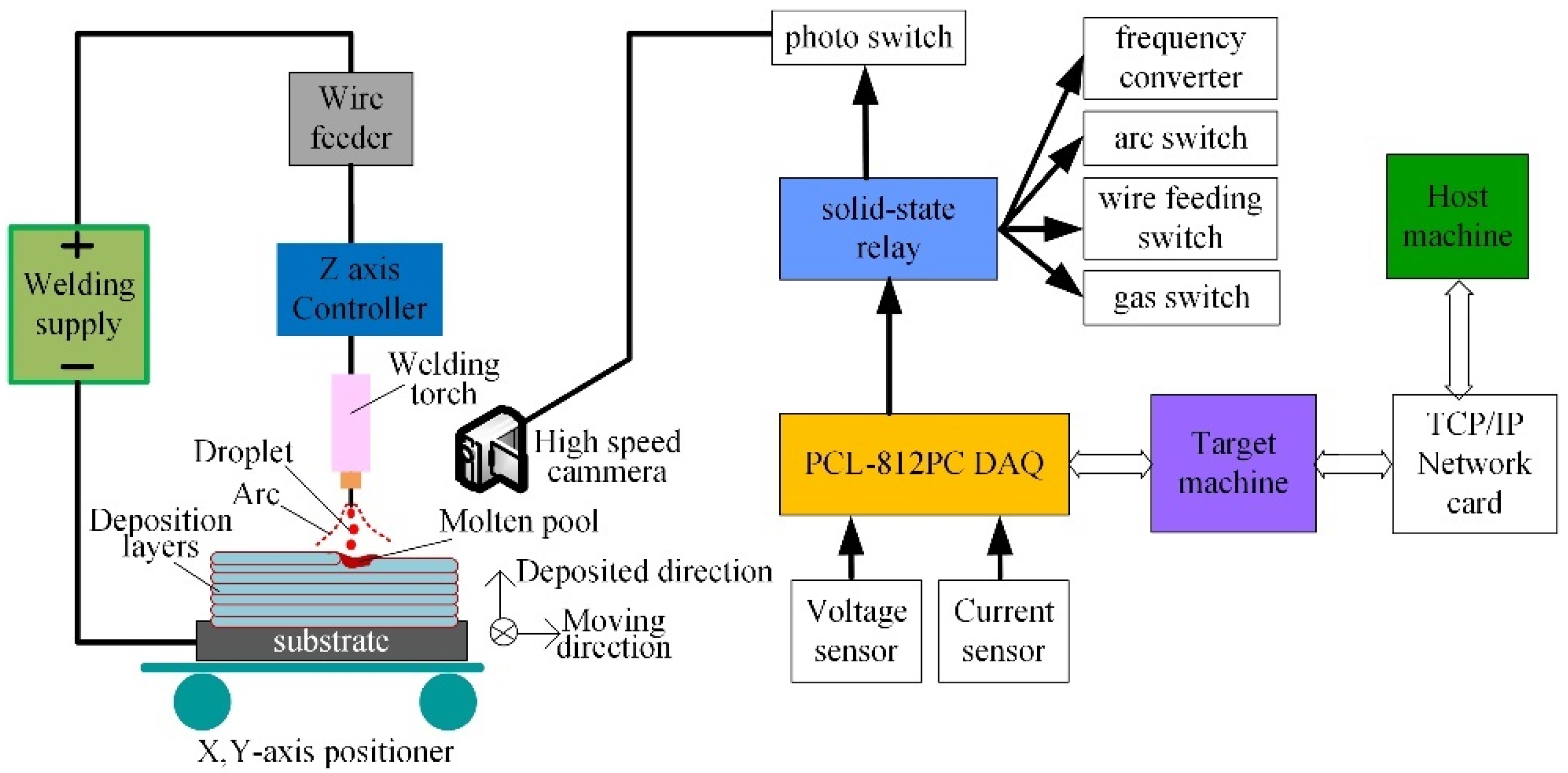
A rapid prototype of a GMA–additive manufacturing system, shown in Figure 1, was established to control the deposition parameters and acquire electric signals. This system mainly included three parts: a rapid prototyping system, a vision-based acquisition system, and a welding system.
The rapid prototype system consisted of host and target computers and a data acquisition card, as well as MATLAB/Simulink XPC Target software tools (MathWorks corporation, Natick, MA, USA). Before starting the experiment, the host computer transmitted the welding parameters to the target machine to automatically conduct the experiments. The motion system was controlled by the motion control card embedded in the host computer. The current and voltage signal acquisition system included a Hall current sensor CSM500FA/100 mA (Xian Pushuo Electric company, Xi’an, China). To accurately acquire the arc voltage and the current data, the Advantech ADAM-3014 isolation module (Advantech Technology China Co., Ltd., Shenzhen, China) was applied in the Advantech PCL-812PG data acquisition. A high-speed camera made by Olympus Corporation was used to sample the metal transfer and the arc dynamics in the GMA–AM process. The deposition parameters are shown in Table 2. A K1346-13/Idealarc® CV400 MIG Welder (Lincoln, Cleveland, OH, USA) was employed to output the arc energy, and also an LN-7 GMA wire feeder was used to fill the wire.
In this work, experiments were designed by applying direct current (DC) and pulsed current (PC), and were performed to investigate the effect of arc–droplet interactive behavior on the deposition morphology when the heat input to the substrate was kept constant. In the DC GMA–AM process, a constant voltage welding machine was used and the welding current was adjusted by the wire feed speed. In the PC GMA–AM process, a DELEX VIRIO MIG-400L welding supply was used to output a pulsed current waveform with a constant current source. The deposition direction is shown in Figure 1. The pulsed parameters are listed in Table 3.
The parameters listed in Table 2 and Table 3 are the optimized parameters determined from many previous experiments. To determine the influential mechanism of the process parameters on the forming accuracy of the AM, two experiments with different deposition morphologies in the DC GMA–AM process were selected in this section. Although the parameters listed in Table 2 affect the arc shape, the droplet transfer, and the molten pool dynamics, all the actions of these parameters can be normalized by the heat input. Furthermore, the GMAW process is stable when the melting speed of the solid wire is equal to the wire feeding speed when the moving speed of the work piece is constant. The wire extension can be maintained at a certain length due to the inherent arc self-regulation, which determines a stable arc voltage with low fluctuation. Hence, only the voltage parameter in Table 2 was selected as the variable. In the PC GMA–AM process, the purpose of these experiments performed with the parameters in Table 3 was to demonstrate the feasibility of controlling the heat accumulation and the droplet transfer mode by adjusting the peak current. Meanwhile, the peak current of the pulsed GMAW process was mainly used to melt the solid wire and the substrate. The base current was only used to keep the arc burning constantly. Therefore, the amount of the heat input to the molten pool mainly depended on the peak current and its action time, namely the duty ratio. Hence, the variation in the peak current was only used to reveal the change in the heat input to the molten pool and the final forming accuracy.
The wall-like AM parts were cut using a wire cutting machine, and their cross-sections were mechanically ground and polished to obtain a mirror-like surface by following a standard metallographic procedure. The microstructure of the parts was observed and analyzed by optical microscopy (OM) and scanning electron microscopy (SEM). Microhardness measurements were carried out on the as-etched specimens, in compliance with ISO 6507–1, using a Zwick/Roell ZHV Vickers (ZWICK ROELL Co. Ltd., Frankfurt, Germany) hardness tester equipped with an optical microscope. On each layer of the deposition, 20 points were selected to perform the microhardness measurements. The average hardness of these locations was also computed, and the variation in the average hardness of the different layers was analyzed. A 200 N load with a dwell time of 10 s was used for all indentations.
3. Results and Discussion
3.1. Deposition Morphology
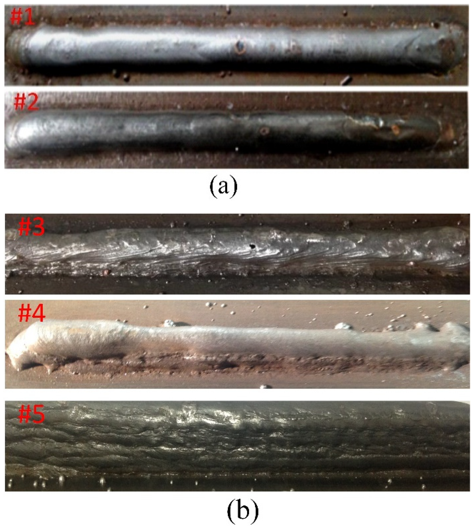
The series of experiments were repeatedly conducted by using the parameters listed in Table 1 and Table 2, and the final morphologies are shown in Figure 2.
Figure 2a shows the deposition results of the DC GMA–AM process with different droplet transfer modes. As Figure 2a #1 shows, there is a small variation in the width and the height of the deposited layers in the vertical and the horizontal directions with the same depositing parameters, and a vertical wall with six layers was eventually obtained. Figure 2a #2 shows the morphology manufactured by a low heat input, the same wire feeding speed, and the same depositing speed with sample #1. The morphology of the surface is not smooth and a few pores are present. The width and the height of the layers deposited by the globular transfer mode change significantly, and only four layers were deposited. The morphologies of the additively manufactured parts agree with the results reported by Xiong [36]. It was also demonstrated that the more heat input to the substrate plate, the lower the accuracy of the AM part.
Aldalur determined that the pulsed GMAW process can more easily achieve a low heat input and generate a small droplet transition compared to the conventional GMAW process [37]. Figure 2b #3 depicts the formation deposited by the one droplet multi-pulse mode in a single bead multi-layer of the PC GMA–AM process. According to Zhai’s comparative study of droplet transfer modes on weld bead appearance during pulsed GMAW, a better weld bead appearance with a small penetration/width ratio and lower fuming on the steel plate could be achieved with the one droplet per pulse welding process [35]. This geometrical weld bead is more beneficial for deposition of the next layer. The analysis indicates that the droplet is transferred from the wire tip to the molten pool by the one droplet multi-pulse mode, and the arc dynamic might be fully changed or even be extinguished in the base current period due to the large difference between the pulse peak current period and the pulse base current period. This action restrains the fluid flow of the weld metal and disturbs the solidification of the weld pool. The final deposition appearance is uneven and sunken, which impedes the subsequent formation of the liquid metal. Figure 2b #4 shows the formation deposited by the multi-droplet per pulse transfer mode. In this case, a high depositing efficiency could be obtained, but a larger arc energy is needed to melt the solid wire quickly; thus, the heat input to the molten pool quickly increases, which in turn disturbs the force balance of the molten pool boundary, resulting in a poor forming accuracy. What is more, most of the previous layer of the deposition may re-melt, resulting in a morphology with a lower depth/width ratio. When the droplet was transferred by the one droplet per pulse mode, a high quality deposition was obtained because of the dynamic balance between the heat input and the droplet transition. With appropriate depositing and wire feed speeds, the droplet transferred by the one droplet per pulse mode can be adequately spread on the substrate or the deposition surface, but also the heat input to the substrate can be precisely controlled, maintaining the uniformity and the continuity of the weld metal solidification. At last, a high quality deposition is generated, as shown in Figure 2b #5. According to the results of Zhai’s investigation [35], they postulated that the droplet transfer frequency and its dimensions significantly affect the penetration and the width of the molten pool. This conclusion fits with our experimental results. However, the reasons given by Zhai do not fully explain our results. They suggested that the high frequency impact of the droplet on the molten pool increases the penetration; however, we regard this as a result of the contribution of the excessive heat input from the arc energy, because if the multi-droplet per pulse mode is generated in the GAMW process, a large current and a long arc length have already been set, which generates more arc heat.
The above experiments demonstrate that the forming accuracy of the PC GMA–AM process is clearly higher than the DC results, which is in accordance with the study of Aldalur Eider [38]. In order to clearly understand the influential mechanism of the welding current waveform on the deposition morphology and to precisely control the forming accuracy of the AM parts, in this study, the arc–droplet interaction, which is closely related to the final manufactured shape, was visually analyzed by using captured images and welding physics.
3.2. Arc Characteristics and Droplet Transfer Behavior in the GMA–AM Process
3.2.1. DC GMA–AM Process
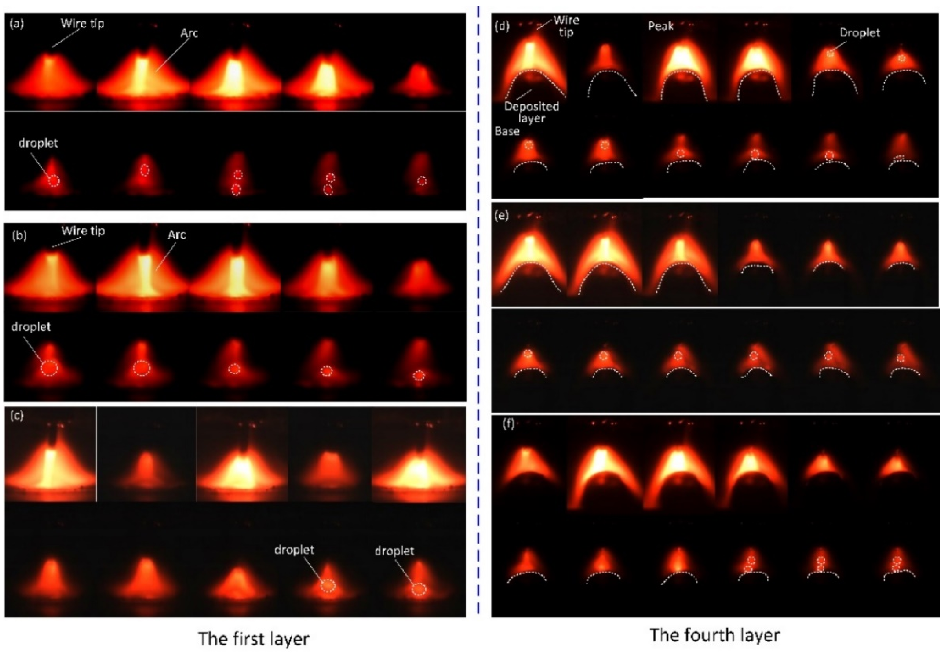
To clearly understand the different mechanisms of the droplet transfer and the arc dynamics in the deposition process from bottom to top of the wall, in this section, images of the arc shapes and the droplet transfer were taken by a high speed camera at 2000 fps. The images of the arc shape and the droplet are shown in Figure 3. The No #1 parameters listed in Table 2 were chosen in this experiment because of the stable mass transfer process and a better weld bead shape, shown in Figure 1a.
Figure 3a,b shows typical images of the arc shape and the droplet transfer when depositing the first layer on the substrate. The arc shape shows a typical bell-like geometry, and the droplet drops from the wire tip using a spray transfer mode and enters the molten pool along the positive direction. According to the explanation of Xiong [36], this phenomenon always occurs in the conventional GMAW process, and the stability of the arc–droplet system mainly depends on a balance between the wire feed speed, the welding speed, the arc voltage, and the substrate dimensions. Thus, the final shape can be manipulated by controlling the arc length and the droplet transfer mode. Moreover, the heat input to the molten pool can be quickly dissipated via a substrate with large dimensions, and then a good weld bead with the desired depth-to-width ratio is finally obtained.
Xiong investigated the effects of the main process parameters such as the inter-layer temperature, the wire feed speed, the travel speed, and the ratio of wire feed speed to travel speed on the surface roughness of thin-walled parts by using process experiments and modeling simulations [36]. However, the evolution of the droplet, the arc shape, or the molten pool dynamics do not explain the physical processes. Changes in the arc voltage and the heat input to the molten pool with an increase in the deposition layer could alter the droplet transfer mode, which further determines the droplet mass transfer from the wire tip to the molten pool. Therefore, precise control of the droplet transfer is very important and assists in generating a consistent and uniform deposition layer. Consequently, it is necessary to study the arc dynamics and the droplet transfer behavior in the GMAW–AM process.
Typical images of the arc shape and the droplet captured at the fourth layer are shown in Figure 3c and Figure 3d, respectively. They show that the arc shape has clearly changed, and the cathode spot moves from one side to the other side of the molten pool, causing the liquid metal to fluctuate. Moreover, the droplet transition changes from spray transfer to globular transfer, and even a short circuit transition occurred between the higher melting layer and the wire tip, which easily causes the molten pool to lose stability in the additive manufacturing process due to heat accumulation. From the arc self-regulation principle of the constant supply of welding voltage, it is indicated that the intrinsic adjustment of the arc length weakens the arc stability when the arc voltage is reduced and the height of the deposited layer is increased.
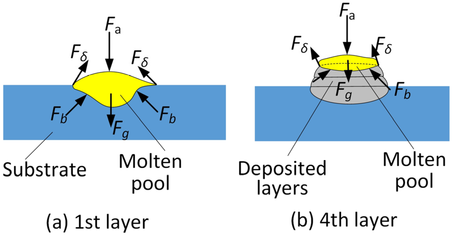
A comparison of Figure 3a,c indicates that the location of the cathode spot on the molten pool surface changes to be more acute and flexible, resulting in a varying droplet transfer axial direction, which also seriously affects the splash phenomenon because the partial droplet metal is transferred from the wire tip to the molten pool. This leads to an unstable mass transfer process in each of the deposition layers. The heat–mass transmission plays a dominant role in determining the deposited precision of the part. In particular, the thermal force balance of the molten pool directly decides the forming accuracy of the GMA–AM components. In addition, in the DC GMA–AM process, the influence of the heat accumulation on the stability of the molten pool is reflected more significantly in the third deposition layer, and thus the final, sixth layer was deposited by using the same parameters as the first layer deposition. According to Zhao’s reports [39], the distribution of the forces acting on the molten pool is shown in Figure 4. Figure 4a,b shows the loading states of the molten pool in the first layer and the fourth layer, respectively. When the arc–droplet transfer process is stable in the GMA–AM process, the final morphology and accuracy are mainly determined by the volume size and the dynamic stability of the molten pool. A lower depth-to-width ratio of the molten pool is expected to maintain the height and the width of the deposition layer; therefore, the heat input to the current molten pool should be low to re-melt the previous deposition layer as little as possible. Thus, the force balance of the molten pool mainly depends on the surface tension, Fδ, and the joint force of the arc force and gravity, which is illustrated in Figure 4b. With the increase in the number of depositing layers, there are two main changes in the molten pool. One is that a small change in the braced force, Fb, occurs due to the lower amount of remelted previous deposition layer, and another is that the surface tension, Fδ, changes less because of the increase in the temperature of the molten pool brought about by the heat accumulation. Therefore, the boundary of the molten pool easily loses balance, resulting in a side-stream shape. This has been demonstrated in Zhao’s results [39]. Hence, precisely controlling the heat input to the molten pool is the key to achieving a good deposition morphology with the desired accuracy.
3.2.2. PC GMAW–AM Process
In this section, a pulsed current was employed to reduce the heat input and precisely control the droplet transition. In the pulsed GMA–AM process, some pulsed parameters need to be adjusted to meet the requirements of the arc–droplet system. Therefore, the effects of the pulsed parameters on the droplet transfer behavior and the forming accuracy were carefully studied. In these experiments, the moving speed of the work piece was 3.2 m/min and the wire feeding speed was 6.35 cm/min. The other parameters are shown in Table 3.
The captured images of the arc and the droplet are shown in Figure 5. Figure 5a–c shows typical images of the arc shape and the droplet transition using the multi-droplet per pulse cycle, the one droplet per pulse cycle, and the one droplet multi-pulse cycle mode in the deposition of the first layer deposition, respectively. Figure 5d–f shows typical images of the arc shape integrated with the droplet using the one droplet multi-pulse cycle, the one droplet one pulse cycle, and the multi-droplet per pulse cycle mode in the deposition of the fourth layer, respectively.
When the peak current was 420 A, the droplet transition presented a one droplet multi-pulse transfer mode. This is because the peak current is too small, resulting in a low heat input and a small electromagnetic contraction force acting on the liquid wire tip to transfer the droplet. Therefore, the solid wire was melted by increased energy derived from the pulsed current and the resistance heat and a larger droplet was generated. Thus, the liquid metal might be transferred to the molten pool by overcoming the surface tension. When peak current was 500 A, the droplet was transferred by using the one droplet per pulse pattern, and had smaller dimensions, which can be seen in Figure 5b. When the peak current was further increased to 580 A, the droplet transfer mode was changed from the one droplet per pulse to the multi-droplet per pulse cycle due to the larger heat input and the larger electromagnetic contraction force, as well as the smaller surface tension of the wire tip. Finally, the spray transfer mode occurred, which can be seen in Figure 5a.
As seen in Figure 5d–f, the most stable additive manufacturing process is when the droplet transition occurs using the one droplet per pulse cycle pattern. According to Zhu’s reports [40], the combination of the pulsed arc and the pulsed droplet transfer mode obtains the best thermal and the mechanical transfer characteristics, which is more suitable for the WAAM process. Moreover, in the peak current period, the arc energy is mainly used to melt the solid wire and fuses the pre-deposited solidification layer to form a molten pool with a fixed voluminal size. The melted droplet could separate from the wire tip and enter the molten pool along the axial direction of the arc column. Furthermore, the arc length, in this transfer process, could be appropriately adjusted by the arc intrinsic self-regulation of GMAW, which is shown in Figure 6, and thus the arc could be kept very stable, which in turn maintained the uniformity and continuity of the deposited layer width.
Bingül reported that the arc inherent self-regulation strongly affects the stability of the arc–droplet system in GMAW [41]. In Figure 6, the Am line is the external characteristic of the welding supply. Bm1 and Bm2 show the static variations in the long and short arc of the GMAW, respectively. Cm is the wire feed rate which is equal to the wire melting speed.
When the arc length is reduced, the static curve changes from Bm1 to Bm2. Consequently, the current fusing wire increases from Im1 to Im2. The correlation of the melting rate with the welding current shows that the melting rate increases, which can be shown by Vm2 > Vm1. Their correlations can be expressed by the following:
where Ki and Ku represent the current and the voltage melting coefficients, respectively. These values correlate to the resistivity, diameter, wire extension, and the potential gradient of the arc column. The value, in this work, is considered as a constant.
When the equal working point of the arc changes from the Om1 to Om2, despite the Om2 meeting the characteristic matching requirement between the weld power source and the arc, it cannot satisfy the balance of the wire feed and the melting speeds. The increased current melts more wire and the arc length increases. Consequently, the new balance point of the arc can only be achieved by regulating the melting rate of the wire. When the wire extension is reduced, the burning arc moves to the conductive nozzle and ceases the welding process when the conductive nozzle is completely melted. Hence, in this process, the arc inherent self-regulation was achieved by adjusting the wire feed speed.
In brief, the experiments designed with different current waveforms and the analyses of the GMA–AM process demonstrate that the arc–droplet interaction could be weakened by the liquid bridge transfer mode in the DC GMA–AM process, and the heat mass transfer could be precisely controlled by using the one droplet per pulse mode in the PC GMA–AM process. However, the significant heat accumulation in the molten pool could not be appreciably weakened in these AM processes; the final deposition morphology was poor and the forming accuracy was low. Therefore, effectively reducing the heat accumulation of the molten pool to maintain its dynamic balance and maintain this status in the next deposition is key to improving the AM accuracy of the parts. Lots of publications have reported many new methods for resolving this problem, including interlayer cooling, immerged water cooling, liquid nitrogen cooling, and low heat input welding methods [42,43,44,45]. Although these methods are able to reduce the heat accumulation to a certain extent, they reduce the deposition efficiency, enhance the complexity of the AM equipment, and so on. That is to say, the mentioned approaches have not completely resolved heat accumulation. Based on this work, we have proposed a novel idea that the heat accumulation might be used as a part of energy to melt the previous solidified metal, i.e., the heat input to molten pool. In summary, the energy utilized to form the molten pool includes two parts: the arc droplet heat input and the heat accumulation. Based on this assumption, we have conducted some works, including mathematical modeling and experiments, which will be presented in the next publication.
3.3. Microstructure and Microhardness of the Deposited Layers
Based on the analysis of the arc–droplet transfer behavior of PC GMA–AM and the observations of the deposition morphologies, it was shown that the thermal mass transfer mode can be precisely controlled by adjusting the pulsed parameters. Moreover, the pulsed current can stir the molten pool and refine the grain structure, which has been reported in the literature [37]. Hence, in this section, the cross-sections of the parts with PC application were analyzed, and their microhardnesses were measured. The optimized No #5 parameters in Table 3 were chosen. The interlayer temperature was precisely controlled by the cooling time (1 min, 3 min, and 5 min), and then three deposited parts with ten layers were obtained, which are shown in Figure 7.
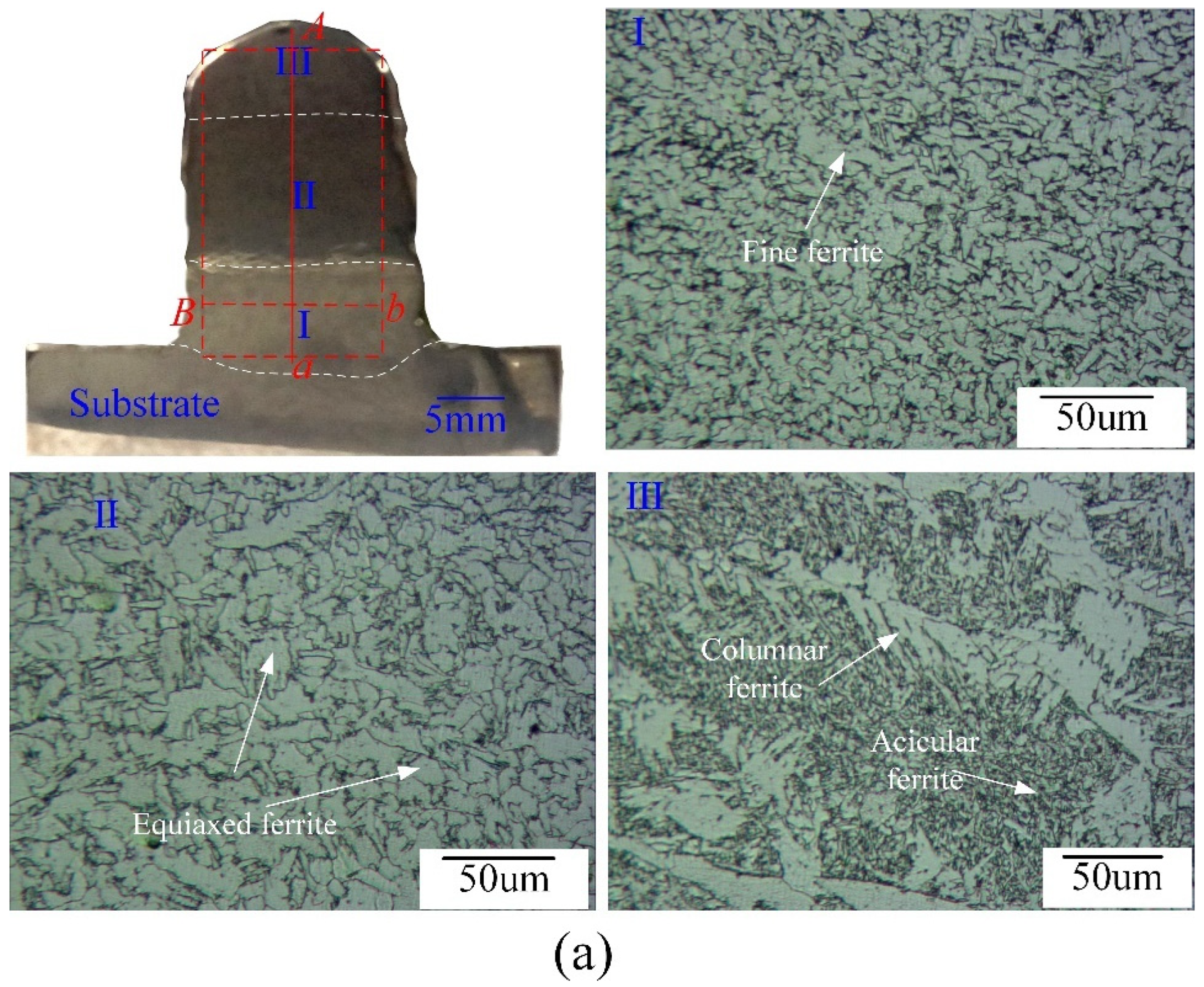
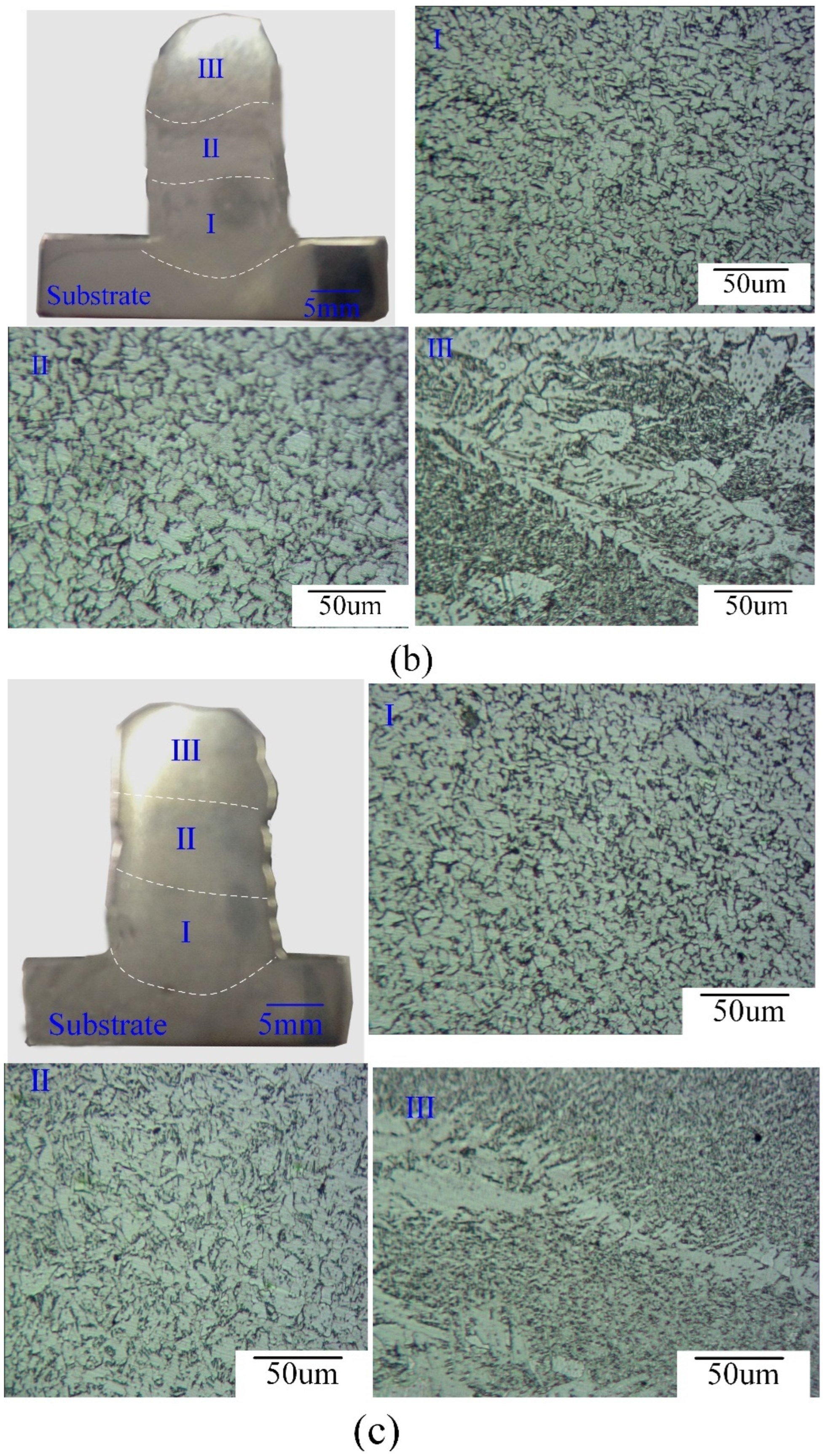
The morphologies of the parts shown in Figure 7 indicate that the depth and the height of the molten pool clearly changes with an increase in the interval cooling time. Along with the deposition direction, the thin-walled parts were divided into three regions, including the top section III, middle section II, and bottom section I. The three regions were analyzed by optical microscopy and SEM. The results show that the microstructure of the parts is almost completely composed of ferrite, with a smaller pearlite phase. The morphologies of the ferrite can be classified into four types, a fine ferrite phase, an equiaxed ferrite phase, a columnar ferrite phase, and acicular ferrite, which is shown in Figure 7a. These experimental results agree with those of Hu [46]. Moreover, in a comparison with Hu’s results [46], it was found that the grain size of the AM parts obtained by our method is smaller, and the grain structure is well distributed in the bottom and middle areas.
It is shown in region I in Figure 7 that the fine ferrite structure was generated, although the interval cooling time changed from 1 min to 5 mins. Compared with the middle areas, it could be seen that the ferrite grains were equiaxed, especially on the grain boundary, and the grains in Figure 7c, image II were the smallest. At the top of the samples in Figure 7a, region III, it was shown that there was columnar ferrite located at the grain boundary and acicular ferrite located in the grain. The top of the sample in Figure 7b and the sample in Figure 7c indicate that there was a narrow columnar ferrite. As a result of the different rapid solidification processes with different cooling times, the heat accumulation largely determined the final microstructures of the deposited parts. A lower heat accumulation resulted in the formation of fine equiaxed grains, which might significantly affect the mechanical properties of the deposited component [46,47].
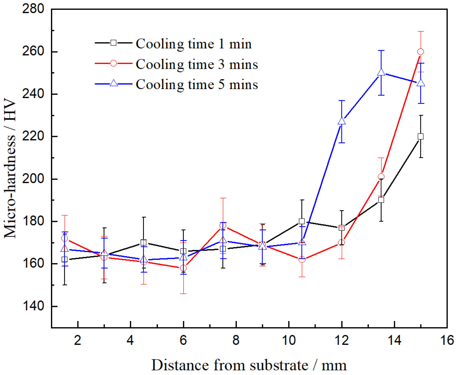
Figure 8 depicts the microhardness (HV) distribution of the samples in the cross-sections shown in Figure 7. Figure 8 shows the hardness curve of the samples from the center axis of the bottom to the top with different heat accumulations. From the hardness curves, it was shown that the hardnesses of the three samples were similar to each other in the bottom and the middle regions, while the hardness curves at the top of the cross-sections were different. The average hardnesses of the bottom and the middle areas of samples were below 180 HV. However, the hardness of the top area of the samples clearly changed from 220 HV to 260 HV. From the three hardness curves, it was clearly observed that the hardness at the top of the surface area with a cooling time of 3 mins was the highest, as coarse ferrite grains were formed under a suitable thermal cycle temperature. In addition, it was easily found via a comparison with the literature [46] that the average hardness of the parts made with PC GMA–AM was higher than those made with DC GMA–AM because of the strong stirring action of the pulsed arc force in the molten pool and the restraining action of the lower heat input.
4. Conclusions
In this study, the effects of the process parameters on the arc shape, the droplet transfer mode, the deposition morphology, and the hardness in pulsed GMA–AM were experimentally investigated, and its influential mechanism was discussed. The conclusions are as follows:
(1) In the DC GMA–AM process, although a sound deposition morphology can be achieved by using the droplet spray transfer mode, the stable AM process can be easily disturbed owing to the arc self-regulation, accumulating too much heat to finish the entire AM process. In the PC GMA–AM process, the one droplet per pulse cycle droplet transfer mode is considered as the best transfer pattern, producing a more accurate deposition formation.
(2) The constant current welding supply is more suitable for application in GMA–AM because of the weakened arc self-regulation, and using a pulsed current in the GMA–AM process more easily and precisely controls the heat input and the heat accumulation to achieve a high deposition accuracy of the parts.
(3) The heat input not only affects the droplet transfer behavior but also changes the spreading behavior of the liquid metal on the substrate, as well as the thermal force balance of the molten pool in different deposition layers. The proposed strategy uses the heat accumulation of the previous deposition to compensate for the energy formed in the molten pool, potentially significantly reducing the heat accumulation and producing highly accurate AM components.
(4) The microstructure of the deposited parts in the middle region was equiaxed ferrite grains. With an increase in the interlayer cooling time, the microstructures of the bottom, middle, and top regions were fine ferrite, equiaxed ferrite, and columnar ferrite integrated with acicular ferrite and a lower proportion of pearlite, respectively. The average hardnesses of the bottom, middle, and top areas along the deposited direction were ~168 HV, ~175 HV, and ~250 HV, respectively.
Author Contributions
G.Z. and G.H. prepared the materials and experiments, including material research, experimental scheme design, and experimental conduction. Y.G. and Y.S. analyzed the experimental results, including conceptualizing the GMA–AM process and explain the experimental phenomena, as well as analyzing the microstructure. All authors have read and agreed to the published version of the manuscript.
Funding
This research was funded by the National Natural Science Foundation of China (grant no. 52265050), the Key research and development program of GanSu (grant no. 20YF8GA054), the Natural Science Foundation of GanSu (grant no. 20JR5RA455), the CAS “Light of West China” Program (grant no. 21JR7RA202), the Hong Liu Outstanding Talent Training Plan of Lanzhou University of Technology (grant no. 2018A-022), and the open fund of Opto-Mechatronic Equipment Technology Beijing Area Major Laboratory (grant no. 2019A-001). The authors are grateful for the support.
Data Availability Statement
The data used to support the findings of this study are available from the corresponding author upon request. All relevant data are available on reasonable request.
Acknowledgments
Thanks to the support of the National Natural Science Foundation of China.
Conflicts of Interest
The authors declare no competing interest.
References
- Müller, J.; Grabowski, M.; Müller, C.; Hensel, J.; Unglaub, J.; Thiele, K. Design and parameter identification of wire and arc additively manufactured (WAAM) steel bars for use in construction. Metals 2019, 12, 725. [Google Scholar] [CrossRef] [Green Version]
- Huang, R.; Riddle, M.; Graziano, D.; Warren, J.; Das, S.; Nimbalkar, S. Energy and emissions saving potential of additive manufacturing: The case of lightweight aircraft components. J. Clean. Prod. 2016, 135, 1559–1566. [Google Scholar] [CrossRef] [Green Version]
- Venturini, G.; Montevecchi, C. Feature based three axes computer aided manufacturing software for wire arc additive manufacturing dedicated to thin walled components. Addit. Manuf. 2018, 22, 643–657. [Google Scholar] [CrossRef]
- Knezovi, N.; Topi, A. Wire and Arc Additive Manufacturing (WAAM)—A New Advance in Manufacturing; Springer: Cham, Swizerland, 2019; pp. 65–71. [Google Scholar]
- Giganto, S.; Martínez-Pellitero, S.; Barreiro, J.; Zapico, P. Influence of 17-4 PH stainless steel powder recycling on properties of SLM additive manufactured parts. J. Mater. Res. Technol. 2022, 16, 1647–1658. [Google Scholar] [CrossRef]
- Nirish, M.; Rajendra, R. Suitability of metal additive manufacturing processes for part topology optimization-a comparative study. Mater. Today 2020, 27, 1601–1607. [Google Scholar] [CrossRef]
- Lewis, G.; Schlienger, E. Practical consideration sand capabilities for laser assisted direct metal deposition. Mater. Des. 2000, 21, 417–423. [Google Scholar] [CrossRef]
- Kumar, S.; Elangovan, S.; Mohanraj, R.; Narayanan, V. Significance of continuous wave and pulsed wave laser in direct metal deposition. Mater. Today 2021, 46, 8086–8096. [Google Scholar]
- Tang, Q.; Pang, S.; Chen, B.; Suo, H.; Zhou, J. A three-dimensional transient model for heat transfer and fluid flow of weld pool during electron beam freeform fabrication of Ti-6-Al-4-V alloy. Int. J. Heat Mass Tran. 2014, 78, 203–215. [Google Scholar] [CrossRef]
- Levy, A.; Miriyev, A.; Sridharan, N.; Han, T.; Tuval, E.; Babu, S.S.; Frage, N. Ultrasonic additive manufacturing of steel: Method, post-processing treatments and properties. J. Mater. Process. Technol. 2018, 256, 183–189. [Google Scholar] [CrossRef]
- Xu, T.; Cui, Y.; Ma, S.; Wang, J.; Liu, C. Exploring the inclined angle limit of fabricating unsupported rods structures by pulse hot-wire arc additive manufacturing. J. Mater. Process. Technol. 2021, 295, 117160–117170. [Google Scholar] [CrossRef]
- Henckell, P.; Gierth, M.; Ali, Y.; Reimann, J.; Bergmann, J. Reduction of energy input in wire arc additive manufacturing with gas metal arc welding. Materials 2020, 13, 2491. [Google Scholar] [CrossRef]
- Wang, Z.; Zhang, Y. A review of aluminum alloy fabricated by different processes of wire arc additive manufacturing. Mater. Sci. 2021, 27, 18–26. [Google Scholar] [CrossRef]
- Ou, W.; Knapp, G.; Mukherjee, T.; Wei, Y.; Debroy, T. An improved heat transfer and fluid flow model of wire-arc additive manufacturing. Int. J. Heat Mass Tran. 2021, 167, 120835–120845. [Google Scholar] [CrossRef]
- Li, J.; Alkahari, M.; Rosli, N.; Hasan, R.; Ramli, F. Review of wire arc additive manufacturing for 3d metal printing. Int. J. Automot. Technol. 2019, 13, 346–353. [Google Scholar] [CrossRef]
- Suárez, A.; Aldalur, E.; Veiga, F.; Artaza, T.; Lamikiz, A. Wire arc additive manufacturing of an aeronautic fitting with different metal alloys: From the design to the part. J. Manuf. Process. 2021, 64, 188–197. [Google Scholar] [CrossRef]
- Andric, Z.; Labudovic, M.; Kovacevic, R. Effect of heat sink on microstructure of three-dimensional parts built by welding-based deposition. Int. J. Mach. Tool Manuf. 2004, 44, 785–796. [Google Scholar] [CrossRef]
- Baufeld, B.; Biest, O.; Gault, R. Microstructure of Ti-6Al-4V specimens produced by shaped metal deposition. Int. J. Mater. Res. 2009, 100, 1536–1542. [Google Scholar] [CrossRef]
- Baufeld, B.; Biest, O.; Gault, R. Manufacturing Ti-6Al-4V components by shaped metal deposition: Microstructure and mechanical properties. Mater. Sci. Eng. 2001, 26, 012001–012011. [Google Scholar]
- Spencer, J.D.; Dickens, P.M.; Wykes, C.M. Rapid prototyping of metal parts by three-dimensional welding. Part I J. Eng. Manuf. 1998, 212, 175–182. [Google Scholar] [CrossRef]
- Zhang, Y.M.; Chen, Y.; Li, P. Weld deposition-based rapid prototyping: A preliminary study. J. Mater. Process. Technol. 2003, 135, 347–357. [Google Scholar] [CrossRef]
- Song, Y.A.; Park, S.; Choi, D. 3D welding and milling: Part I–a direct approach for freeform fabrication of metallic prototypes. Int. J. Mach. Tool Manuf. 2005, 45, 1057–1062. [Google Scholar] [CrossRef]
- Wanjara, P.; Brochu, M.; Jahazi, M. Electron beam free forming of stainless steel using solid wire feed. Mater. Des. 2007, 28, 2278–2286. [Google Scholar] [CrossRef]
- Xiong, J.; Zhang, G.J.; Gao, H.M. Modeling of bead section profile and overlapping beads with experimental validation for robotic GMAW-based rapid manufacturing. Robot. Comput. Integr. Manuf. 2012, 29, 417–423. [Google Scholar] [CrossRef]
- Li, R.; Xiong, J.; Lei, Y. Investigation on thermal stress evolution induced by wire and arc additive manufacturing for circular thin-walled parts. J. Manuf. Process. 2019, 40, 59–67. [Google Scholar] [CrossRef]
- Xiong, J.; Liu, Y.; Yin, Z. Passive vision measurement for robust reconstruction of molten pool in wire and arc additive manufacturing. Measurement 2020, 153, 107407–107414. [Google Scholar] [CrossRef]
- Quinn, T.P.; Szanto, M.; Gilad, I.; Shai, I. Coupled arc and droplet model of GMAW. Sci. Technol. Weld. Joi. 2005, 10, 113–119. [Google Scholar] [CrossRef]
- Xiao, L.; Fan, D.; Huang, J.; Tashiro, S.; Tanaka, M. Numerical study on arc-droplet coupled behavior in magnetic field controlled GMAW process. J. Phys. D Appl. Phys. 2020, 53, 115202. [Google Scholar] [CrossRef]
- Harwig, D.D.; Dierksheide, J.E.; Yapp, D.; Blackman, S. Arc behavior and melting rate in the VP-GMAW process. Weld. J. 2006, 85, 52–62. [Google Scholar]
- Ribeiro, R.A.; Dos Santos, E.B.F.; Assunção, P.D.C.; Braga, E.M.; Gerlich, A.P. Cold wire gas metal arc welding: Droplet transfer and geometry. Weld. J. 2019, 98, 135S–149S. [Google Scholar]
- Zhai, P.; Xue, S.; Wang, J.; Chen, W.; Chen, T.; Ji, S. Effects of arc length adjustment on weld bead formation and droplet transfer in pulsed GMAW based on datum current time. Metals 2020, 10, 665. [Google Scholar] [CrossRef]
- Zhang, G.; Shi, Y.; Zhu, M.; Fan, D. Arc characteristics and metal transfer behavior in narrow gap gas metal arc welding process. J. Mater. Process. Technol. 2017, 245, 15–23. [Google Scholar] [CrossRef]
- Liu, Z. Wire and arc additive manufacturing of metal components: A review of recent research developments. Int. J. Adv. Manuf. Technol. 2020, 111, 2315–2322. [Google Scholar] [CrossRef]
- QueguineurG, A.; RückertF, C.; Hascot, Y. Evaluation of wire arc additive manufacturing for large-sized components in naval applications. Weld. World 2018, 62, 32–39. [Google Scholar]
- Zhai, P.; Xue, S.; Wang, J.; Tao, Y.; Chen, W. Comparative Study of Droplet Transfer Modes on Appearance, Microstructure, and Mechanical Properties of Weld during Pulsed GMAW. Metals 2020, 10, 611. [Google Scholar] [CrossRef]
- Xiong, J.; Li, Y.; Li, R. Influences of process parameters on surface roughness of multi-layer single-pass thin-walled parts in GMAW-based additive manufacturing. J. Mater. Process. Technol. 2018, 252, 128–136. [Google Scholar] [CrossRef]
- Aldalur, E.; Veiga, F.; Suarez, A. High deposition wire arc additive manufacturing of mild steel: Strategies and heat input effect on microstructure and mechanical properties. J. Manuf. Process. 2020, 58, 615–626. [Google Scholar] [CrossRef]
- Aldalur, E.; Veiga, F.; Suárez, A. Analysis of the Wall Geometry with Different Strategies for High Deposition Wire Arc Additive Manufacturing of Mild Steel. Metals 2020, 10, 892. [Google Scholar] [CrossRef]
- Zhao, W.; Wei, Y.; Long, J. Modeling and simulation of heat transfer, fluid flow and geometry morphology in GMAW-based wire arc additive manufacturing. Weld. World 2021, 65, 1571–1590. [Google Scholar] [CrossRef]
- Zhu, L.; Luo, Y.; Han, J. Energy characteristics of droplet transfer in wire-arc additive manufacturing based on the analysis of arc signals. Measurement 2019, 134, 804–813. [Google Scholar] [CrossRef]
- Bingül, Z. Instability phenomena in the gas—Metal arc welding self-regulation process. Part I Mech. Eng. J. Eng. 2002, 216, 899–910. [Google Scholar] [CrossRef]
- Lei, Y.; Xiong, J.; Li, R. Effect of inter layer idle time on thermal behavior for multi-layer single-pass thin-walled parts in GMAW-based additive manufacturing. Int. J. Adv. Manuf. Technol. 2018, 96, 1355–1365. [Google Scholar] [CrossRef]
- Silva, D.; Souza, L.J.; De Araújo, D.M.; De Araújo, D.B. Concept and validation of an active cooling technique to mitigate heat accumulation in WAAM. Int. J. Adv. Manuf. Technol. 2020, 107, 2513–2523. [Google Scholar] [CrossRef]
- Shi, J.; Li, F.; Chen, S.; Zhao, Y.; Tian, H. Effect of in-process active cooling on forming quality and efficiency of tandem GMAW–based additive manufacturing. Int. J. Adv. Manuf. Technol. 2019, 101, 1349–1356. [Google Scholar] [CrossRef]
- Thomas, L.; Akshay, J.; Yash, J.; Henriette, S.; Tonya, W. Concurrent geometry-and material-based process identification and optimization for robotic CMT-based wire arc additive manufacturing. Mater. Des. 2020, 194, 108841–108856. [Google Scholar]
- Hu, Q.X.; Miao, J.Y.; Wang, X.L.; Li, C.T.; Fang, K.W. Microstructure and properties of ER50-6 steel fabricated by wire arc additive manufacturing. Scanning 2021, 2021, 7846116. [Google Scholar] [CrossRef]
- Feng, T.; Wang, L.S.; Tang, Z.M.; Yu, S.W.; Bu, Z.X.; Hu, X.; Cheng, Y.H. Effect of Trajectory Curvature on the Microstructure and Properties of Surfacing Wall Formed with the Process of Wire Arc Additive Manufacturing. Coatings 2019, 9, 848. [Google Scholar] [CrossRef] [Green Version]
Figure 1.
Schematic diagram of the experimental system.

Figure 2.
The additively manufactured morphologies (a) with DC and (b) with PC.

Figure 3.
Typical images of arc shape and droplet transfer with a DC waveform (no #1). (a) Arc shape in the first layer deposition. (b) Droplet transfer in the first layer deposition. (c) Arc shape in the fourth layer deposition. (d) Droplet transfer in the fourth layer deposition.
Figure 3.
Typical images of arc shape and droplet transfer with a DC waveform (no #1). (a) Arc shape in the first layer deposition. (b) Droplet transfer in the first layer deposition. (c) Arc shape in the fourth layer deposition. (d) Droplet transfer in the fourth layer deposition.

Figure 4.
The acting force distribution of the molten pool.

Figure 5.
Typical images of the arc shape and droplet transfer with a pulsed current waveform. (sample #5). (a) Multi-droplet per pulse cycle mode in the first layer deposition. (b) One droplet per pulse cycle mode in the first layer deposition. (c) One droplet multi-pulse cycle mode in the first layer deposition. (d) One droplet multi-pulse cycle mode in the fourth layer deposition. (e) One droplet per pulse cycle mode in the fourth layer deposition. (f) Multi-droplet per pulse cycle mode in the fourth layer deposition.

Figure 6.
Diagram of arc inherent self-regulation.

Figure 7.
Microstructure of the deposited parts with different interval cooling times. (a) 1 min, (b) 3 min, and (c) 5 min.
Figure 7.
Microstructure of the deposited parts with different interval cooling times. (a) 1 min, (b) 3 min, and (c) 5 min.


Figure 8.
Micro-hardness of parts with different interval cooling times.


Table 1.
Chemical compositions of Q235 steel and ER50-6 welding wire (wt.%).
| Elements | C | Mn | Si | S | P | Cu | Fe |
|---|---|---|---|---|---|---|---|
| Q235 | 0.17 | 0.30 | 0.15 | 0.035 | 0.015 | / | Bal. |
| ER50-6 | 0.06–0.15 | 1.40–1.85 | 0.80–1.15 | ≤0.035 | ≤0.035 | ≤0.50 | Bal. |
Table 2.
GMAW–AM depositing parameters.
| No | Voltage (V) | Wire Feed Speed (cm/s) | Moving Speed (cm/s) | Wire Extension (mm) | Heat Input (J/cm) |
|---|---|---|---|---|---|
| #1 | 32~34 | 10.58 | 5.33 | 12 | ~1114 |
| #2 | 28~30 | 10.58 | 5.33 | 12 | ~1013 |
Table 3.
Pulsed GMAW–AM depositing parameters.
| No | Peak Current (A) | Base Current (A) | Pulse Frequency (Hz) | Duty Ratio (%) | Moving Speed (cm/s) | Heat Input (J/cm) |
|---|---|---|---|---|---|---|
| #3 | 420 | 100 | 100 | 20 | 5.33 | ~923 |
| #4 | 580 | 5.33 | ~1103 | |||
| #5 | 500 | 5.33 | ~1013 |
Disclaimer/Publisher’s Note: The statements, opinions and data contained in all publications are solely those of the individual author(s) and contributor(s) and not of MDPI and/or the editor(s). MDPI and/or the editor(s) disclaim responsibility for any injury to people or property resulting from any ideas, methods, instructions or products referred to in the content. |
© 2023 by the authors. Licensee MDPI, Basel, Switzerland. This article is an open access article distributed under the terms and conditions of the Creative Commons Attribution (CC BY) license (https://creativecommons.org/licenses/by/4.0/).
Share and Cite
MDPI and ACS Style
Zhang, G.; He, G.; Gu, Y.; Shi, Y. Effect of Process Parameters on Arc Shape, Macroscopic Features, and Microhardness in Pulsed GMA–Additive Manufacturing. Crystals 2023, 13, 546. https://doi.org/10.3390/cryst13030546
AMA Style
Zhang G, He G, Gu Y, Shi Y. Effect of Process Parameters on Arc Shape, Macroscopic Features, and Microhardness in Pulsed GMA–Additive Manufacturing. Crystals. 2023; 13(3):546. https://doi.org/10.3390/cryst13030546
Chicago/Turabian StyleZhang, Gang, Guanyu He, Yufen Gu, and Yu Shi. 2023. "Effect of Process Parameters on Arc Shape, Macroscopic Features, and Microhardness in Pulsed GMA–Additive Manufacturing" Crystals 13, no. 3: 546. https://doi.org/10.3390/cryst13030546
Note that from the first issue of 2016, this journal uses article numbers instead of page numbers. See further details here.