Article

Magnetic Behavior of the Arrays of Iron Cylindrical Nanostructures: Atomistic Spin Model Simulations

1
Institute of Nuclear Physics Polish Academy of Sciences, 31-342 Kraków, Poland
2
Institute of Spintronics and Quantum Information, Faculty of Physics, Adam Mickiewicz University, 61-614 Poznań, Poland
*
Author to whom correspondence should be addressed.
Crystals 2023, 13(3), 537; https://doi.org/10.3390/cryst13030537
Submission received: 1 March 2023 / Revised: 15 March 2023 / Accepted: 16 March 2023 / Published: 21 March 2023
(This article belongs to the Section Crystalline Metals and Alloys)

Abstract

:
Cylindrical ferromagnetic nanowires are of particular interest in nanomaterials science due to various manufacturing methods and a wide range of applications in nanotechnology, with special attention given to those with diameters less than the single domain limit. In the current study, the simulations of magnetic properties of isolated iron nanowires with a diameter of 5 nm and various aspect ratios, as well as two types of arrays of such nanowires (with hexagonal and square arrangement), were performed using atomistic spin model. In the case of a single nanowire, change of coercive field for different applied field directions with aspect ratio was discussed. It was shown that the evolution of the magnetization reversal mechanism from coherent rotation to domain wall propagation appears with increasing length of single nanowire. For the arrays of cylindrical nanostructures, it was revealed that different number of nearest neighbors for each nanostructure in square and hexagonal arrays have an influence on their magnetostatic interactions, which are the most significant for shortest interwire distances. The corresponding spin configurations during the remagnetization process showed the appearance of intermediate magnetization states (when a part of wires is magnetized parallel and part antiparallel to the field direction), connected with Barkhausen effect, which influence the observed hysteresis curves.

1. Introduction

The rapid development in nanotechnology allows for the fabrication of novel magnetic nanostructures with controlled structure, morphology (size and shape), and chemical composition. From the different geometries of such materials, very attractive seems to be cylindrical nanostructures (e.g., nanowires (NWs), nanopillars, nanotubes, or nanorods), which due to anisotropic morphology and reduced lateral sizes possess specific magnetic properties [1,2,3]. Of particular interest in terms of applications and magnetic properties are ferromagnetic cylindrical nanostructures with diameters in the order of or less than the border of a single domain [4]. The arrays of such structures have a wide application potential, from modern nanoelectronic devices as magnetic memory units, processing units in artificial intelligence systems (molecular neural networks), energy harvesting systems, optoelectronics, chemical and biological sensors [5,6,7,8,9,10,11] to different medical applications [12,13,14]. Further progress in the production of ferromagnetic nanowire arrays as well as their new applications are possible due to the continuous improvement of fabrication methods, which include template-assisted electrochemical deposition [11,15,16,17,18], lithographic techniques [19,20], and others [21], allowing for obtaining preferentially oriented arrays of nanowires with tunable size and interwire distance.
However, despite the significant number of experimental works devoted to study the magnetic properties of arrays of ferromagnetic cylindrical nanostructures, understanding the complex interactions and physical effects in such structures often requires the use of numerical simulations. Numerical methods allow to study the magnetic behavior of individual cylindrical nanowires of different geometry as well as the arrays of them and reveal their magnetic configuration, which is a non-trivial task from the experimental point of view. One of the most important issues in the magnetic behavior of arrays of ferromagnetic nanowires is the understanding the long-range dipolar interactions between such structures. As it has been shown, the dipolar coupling between neighboring wires can have a significant influence on their properties by reducing the coercive field in such assembly [22,23,24], changing the magnetic reversal modes (e.g., coherent rotation, curling) [25], or causing magnetic excitations that are strongly dependent on the demagnetizing field, and interfaces boundaries [26].
It should be noted that different systems of isolated nanowires or arranged in a matrix of cylindrical nanostructures with different ferromagnetic materials composition (Ni, Fe, Co, permalloy, etc.) were examined in previous theoretical investigations [27]. In most cases, various micromagnetic approaches, with the use of OOMMF [25,28,29], Mumax3 [30,31], NMAG [23,32,33], software packages or other theoretical methods [34,35,36,37] are commonly applied. The micromagnetic simulations, as well as analytical calculations, were shown to be very useful techniques for the investigation of single objects and arrays of cylindrical ferromagnetic nanostructures. However, in micromagnetic formalism, the magnetization of material (the atomic dipoles which make up the magnetic material) is approximated by a continuous vector field, whose norm is constant at each point and equal to the saturation magnetization [38], whereas in the current study, we applied the atomistic spin model approach for the investigation of magnetic properties of cylindrical nanostructures. It is based on the localization of unpaired electrons to atomic sites and gives the effective local atomistic magnetic moment [39]. The atomistic approach, in contrast to micromagnetic simulations, takes the detailed atomic structure of the material into account and makes it possible to reveal its impact on the macroscopic behavior of nanostructures. Such an approach is particularly important for few-nanometer-sized structures, where finite-size effects appear and long-range atomic ordering may be limited due to material sizes and surface topography [40]. Previous studies have shown that the atomistic spin model simulations are an essential tool for the investigation of the magnetization reversal modes in small-scale materials, such as few-nanometer sized FePt [41] and CoFeB/MgO nanodots [42,43]. Moreover, atomistic simulations could reveal important role of shape anisotropy or exchange interactions in the elongated structures with different shapes and aspect ratio [44,45].
Here, we present the investigation of magnetic properties of isolated iron cylindrical nanostructures with different aspect ratios, as well as two types of arrays of such nanostructures (with hexagonal and square arrangement) using the atomistic simulations. The study will be focused on the calculations of magnetization curves in different directions of the applied magnetic field with respect to the nanowire axis. In the case of a single nanowire, a wide range of aspect ratio changes was considered, and the mechanisms of magnetization reversal were discussed. The change of magnetization reversal mechanism from coherent rotation to two transverse domain walls formation was observed with increase of nanowire length. For the arrays of nanostructures, the changes in magnetization as a function of the applied field were investigated for different distances between objects. It was shown that different number of nearest neighbors for each nanostructure in square and hexagonal arrays influence their magnetization reversal process. The corresponding spin configurations during remagnetization process were also discussed.

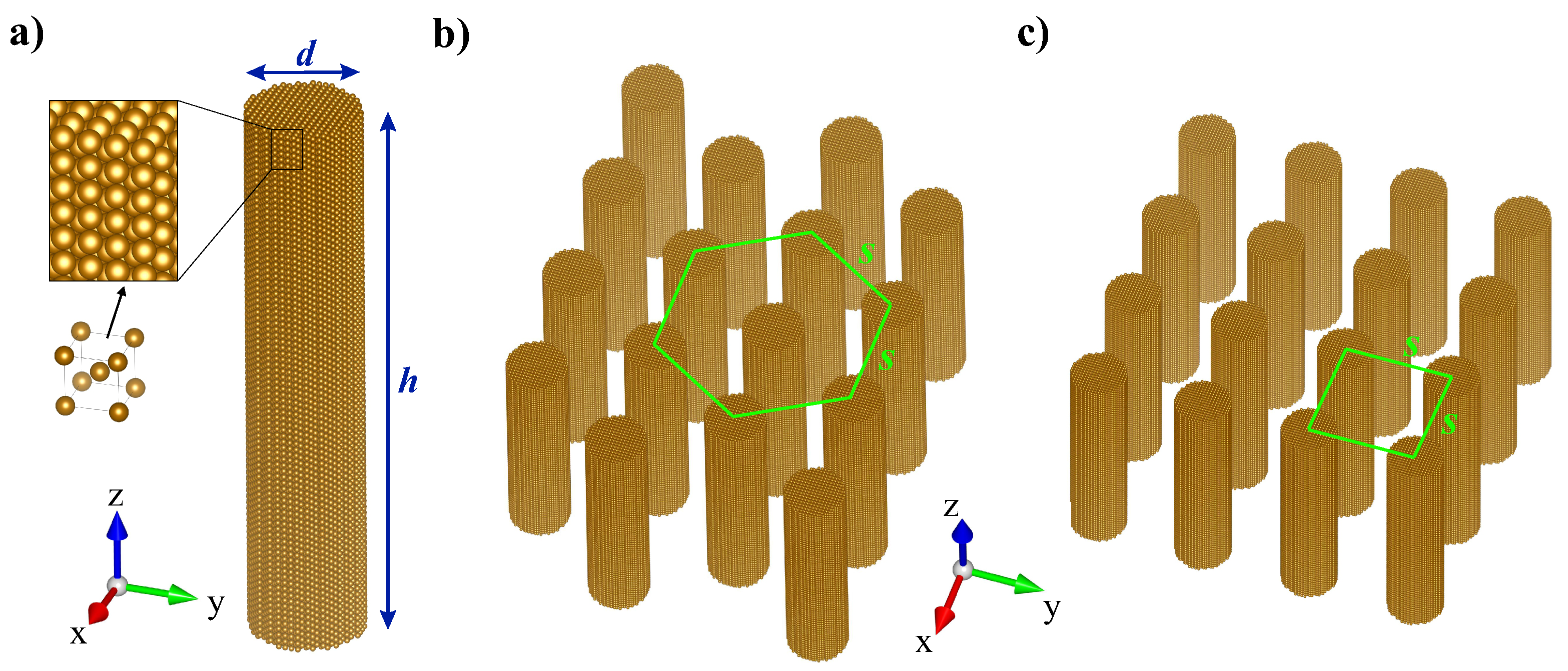
2. Geometry of Materials and Calculation Methods

In the current study, the atomistic magnetic calculations are applied to three different iron-based structures: a single cylindrical nanostructure and two types of arrays of such nanostructures–hexagonal and square (Figure 1). In the case of a single nanostructure, a constant diameter value of d = 5 nm was assumed, and various values of aspect ratio h / d (where h is a nanowire length) were considered. The calculations were done for h / d ranging from the value below 1 to the values of h / d = 20, which corresponds to disklike geometry and elongated structures with a length of 100 nm, respectively. In the case of arrays of cylindrical nanostructures, a constant value of aspect ratio, equal to h / d = 4 was adopted. For both the hexagonal and square arrangements, the same number of nanostructures was assumed for the calculations, namely 16. The magnetic simulations for 4 by 4 arrays of cylindrical nanostructures will enable the reproduction of the magnetic interactions inside the matrix and comparison of the results with experimental data [46,47]. For such materials, the dependence of magnetization on the applied field was calculated for different values of interwire distance s (center-to-center distance between neighboring cylinders). This will provide an opportunity to analyze how magnetic interactions between nanostructures influence their magnetic behavior as a function of interwire distances.
All magnetic calculations in this study were performed with the VAMPIRE software (version 6.0) [39] using atomistic spin model simulations of magnetic nanostructures. To calculate the magnetization curves (magnetization dependence on the applied field), the atomistic Landau–Lifshitz–Gilbert (LLG) Equation (1) was solved using the Heun integration scheme [49], implemented in such software:
S i t = γ 1 + α 2 S i × H e f f i + α S i × S i × H e f f i .
In the above equation, S i is a unit vector representing the direction of the magnetic spin moment of site i, γ is the gyromagnetic ratio, α is the Gilbert damping, which describes the relaxation of the atomic spins caused by electron-electron and electron-lattice interactions and H e f f i is the net effective field acting on the spin i. The atomistic LLG equation takes into account the interaction of an atomic spin moment i with an effective magnetic field ( H e f f i = 1 μ S H S i , where μ S is the local spin moment, and H is the complete spin Hamiltonian of the system) [39]. The Hamiltonian in this case includes the terms of the exchange interaction, magnetic anisotropy, external magnetic field, and dipole field interactions in the following form:
H = i j J i j S i · S j k c 2 i S x 4 + S y 4 + S z 4 i μ s S i · H a p p + H d e m a g .
In the Equation (2), J i j is the Heisenberg exchange interaction between neighboring spins i and j, S i is the normalized vector | S i | = 1 , k c is the local cubic anisotropy constant, S x 4 , S y 4 , S z 4 are the x, y, and z components of the spin moment, respectively, H a p p is the external applied field vector and term H d e m a g describes the magnetostatic contribution and has a form 1 / 2 p m p m c · H d e m a g p , where H d e m a g p is demagnetization field. Note that the demagnetization field is included in the simulations by the macrocell method, which is based on micromagnetic discretization of the system into macrocells [39,42]. Each macrocell in this case has a total magnetic moment m p m c calculated from the vector sum of the atomic moments within each cell. The macrocell size of two unit cells was used for simulated structures.
For the calculations, the bcc iron structures in form of isolated objects with cylindrical geometry or their arrays were generated with the following atomistic parameters: unit cell size of 2.866 Å, atomistic spin moment μ S = 2.22 μ B , exchange energy (between nearest neighbours atomic sites i and j) J i j = 7.05 × 10⁻²¹ J/link and magnetocrystalline anisotropy energy k u =5.65 × 10⁻²⁵ J/atom. Note that for all calculations, the critical value of the Gilbert damping parameter equal to 1.0 was taken, which aims to reproduce results close to quasistatic hysteresis. Based on the LLG-Heun integration scheme, the 20,000 equilibration steps followed by 300,000 averaging steps with the computational time step Δ t = 2.0 fs were used in calculations. In the simulation of M ( H ) hysteresis loops, the magnetic field changed from −20 kOe to 20 kOe with the field increment of 100 Oe. The calculations of hysteresis loops were made assuming a temperature of 0 K to exclude thermal factors.

3. Results of Calculations

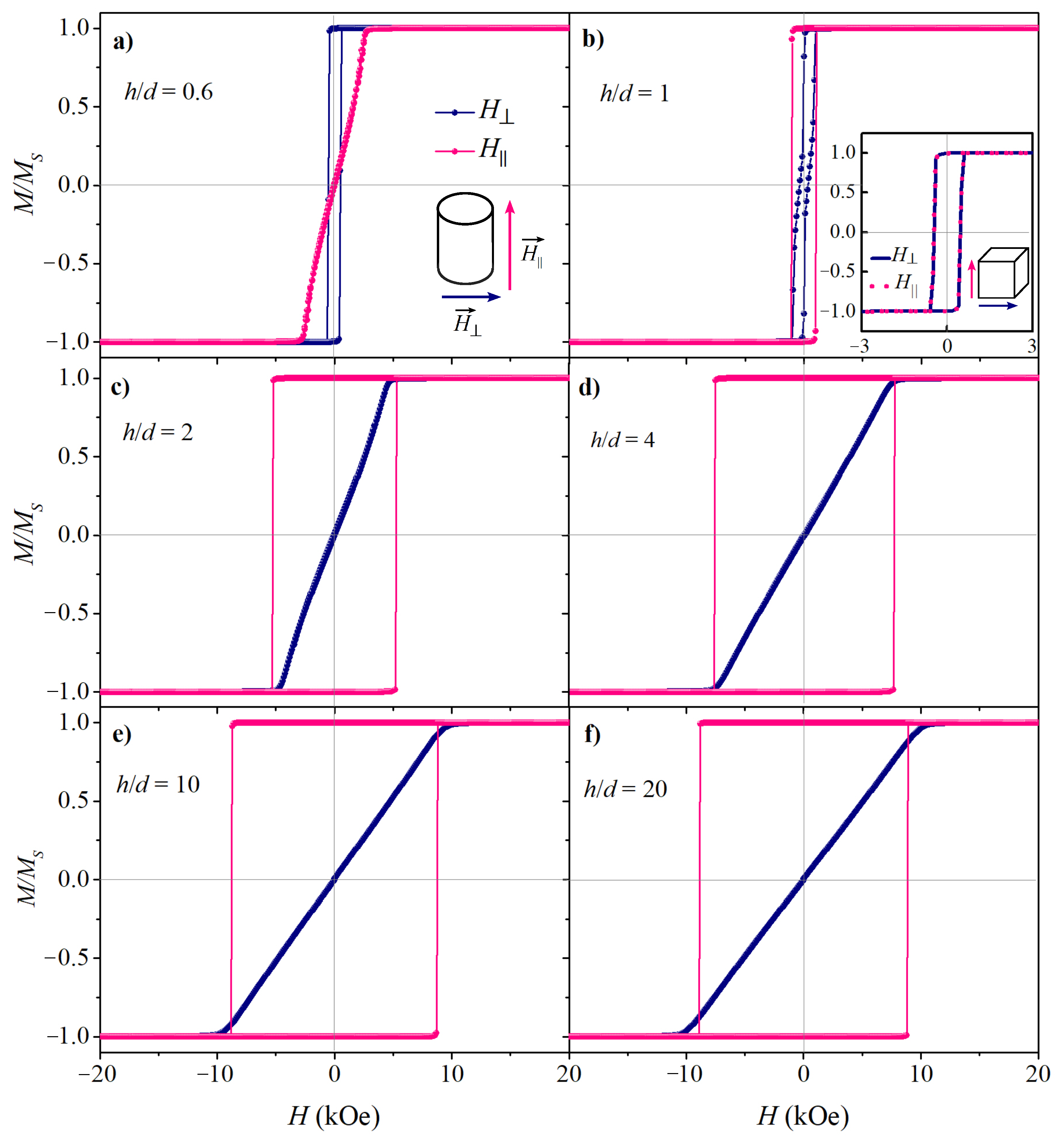
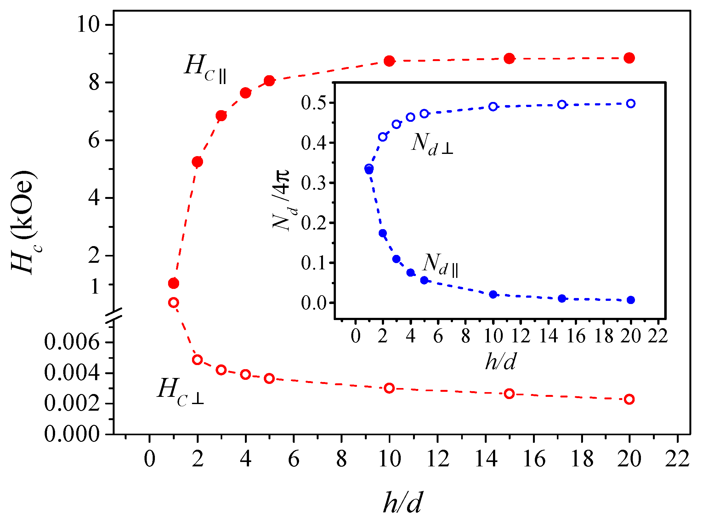
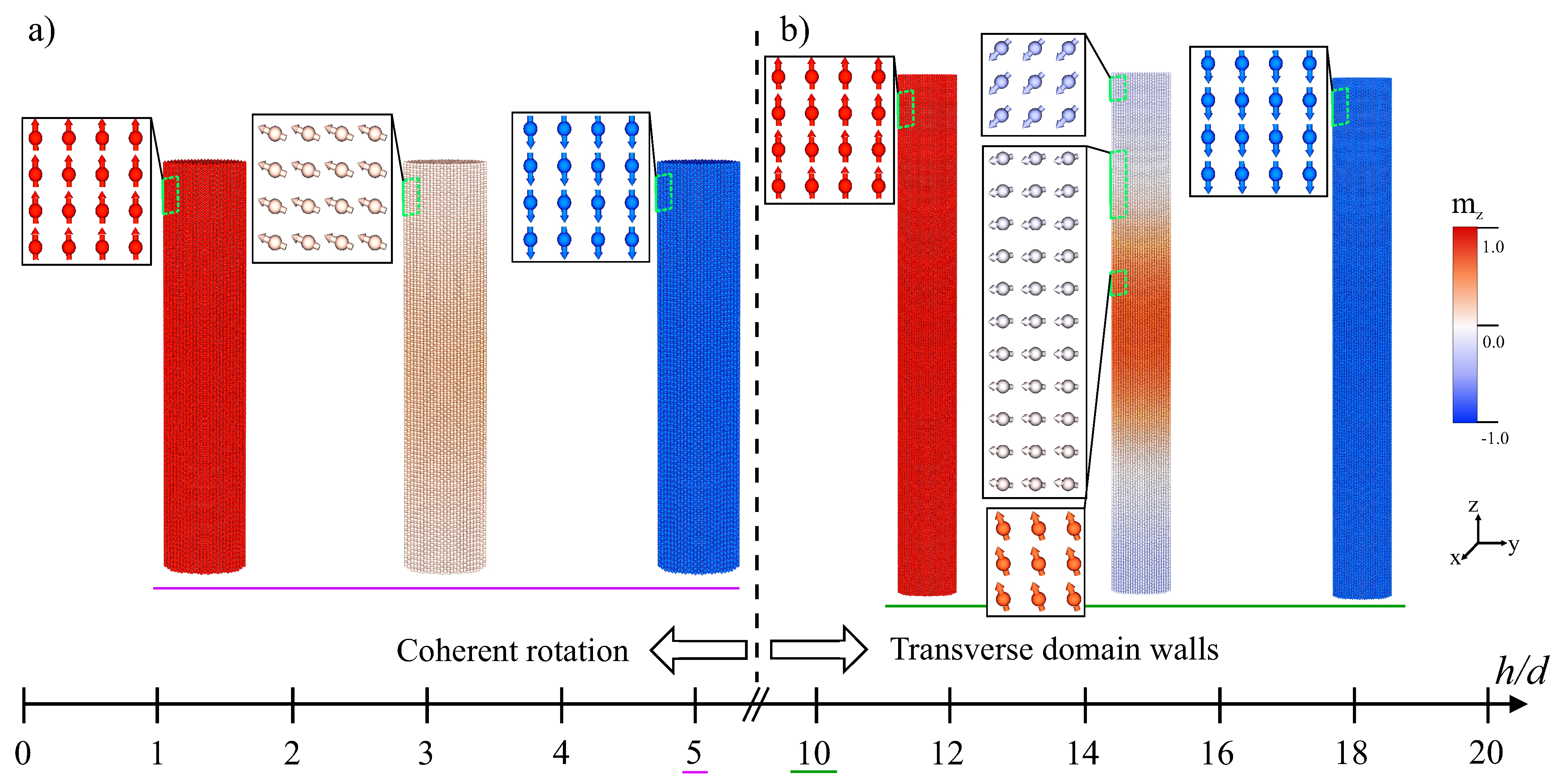
3.1. Isolated Cylindrical Nanostructures

In the first stage of the investigations, calculations of the magnetization dependence on the applied field were performed for isolated iron cylindrical nanostructures with a constant diameter of 5 nm and varied length. The chosen value of diameter implies the uniform (coherent) spin reversal mechanism because the transition from coherent to incoherent rotation occurs at the coherence diameter, which for iron nanostructures is equal to d c o h ≈ 12 nm [50,51].
In the single crystalline cylindrical nanostructures, the effective magnetic anisotropy energy is the combination of the shape anisotropy and the magnetocrystalline anisotropy energy. In Fe nanostructures, the magnetic properties are mostly determined by the shape anisotropy, which dominates over the magnetocrystalline anisotropy and therefore they should strongly depend on the aspect ratio value [52]. The shape anisotropy of a single wire with a high aspect ratio leads to the existence of two stable orientations of the magnetic moment (parallel and antiparallel to the wire axis). However, the situation may be different in the case of cylindrical nanostructures with diameters comparable to or even smaller than their length. We will consider the magnetization curves for a magnetic field applied parallel (out-of-plane) and perpendicular (in-plane) to the axis of nanostructures (h parameter) for a wide range of aspect ratio changes, starting from values below 1. As we can see in Figure 2a for the value of h / d = 0.6 corresponding to a disk-like shape object, the hysteresis loop is much wider for the in-plane applied field, which suggests that the easy axis of magnetization is in the plane of the disks. Such a disk-shaped ferromagnetic structure can be considered as an oblate spheroid and the demagnetization factor for considered aspect ratio can be calculated as shown in Ref. [53]. Taking this into account, for the field applied parallel to the axis of nanostructures (h parameter) the demagnetization factor N along this direction dominates (N = 0.47), which results in a significant decrease in coercivity. On the other side, if the field is applied perpendicular to the axis of such nanostructures, the demagnetization factor is much smaller (N = 0.26) and obtained coercivity is higher. Experimental works on disk-shaped magnetic structures separated by a non-magnetic spacer in multilayered nanowires showed that the dominant anisotropy with the easy axis along nanowires appears for a value of aspect ratio of 0.4 or even lower [54,55]. Such an anisotropy observed for the segments of the disklike shape can be related to the dipole interactions between magnetic parts in the horizontal direction, which could stabilize the anisotropy along nanowires [24].
For the case of aspect ratio equal to 1 (Figure 2b), an almost isotropic magnetic behavior is observed for the parallel and perpendicular directions of the applied field, which is in agreement with experimental observations [25,56]. As we can see from Figure 3, the demagnetization factors value for cylindrical structures [53] with such aspect ratio are unified around the value of 0.33 for both directions. A slight tendency to anisotropy with an easy axis along the main axis can be explained by the cylindrical shape of the object (ideal isotropic magnetic behavior can only be obtained for perfectly isotropic shapes such as spheres or cubes, as shown in the inset of Figure 2b). Additionally, theoretically predicted for a single magnetic cylinder value of the aspect ratio at which the transition between isotropic and anisotropic behavior appears is 0.906 [57]. For the higher values of aspect ratio, the well pronounced anisotropy with an easy axis along nanowires is observed (Figure 2c–f). The coercivity measured at the field applied along the nanowires axis increase rapidly to the aspect ratio value of approximately 4, and then begins to saturate (Figure 3). Such observation is in agreement with experimental data for iron nanowires [50,58] as well as for Co nanowires [59]. The demagnetization factor for parallel orientation decreases with increasing aspect ratio, and for higher values of h / d , it approaches a value close to 0, which results in high anisotropy and coercivity.
In the case of a magnetic field applied perpendicular to the main axis of the cylindrical nanostructures, the magnetic curves do not show visible hysteresis starting from the value of h / d = 2 and coercive field values become almost independent of the object length. The demagnetization factor for this orientation, as opposed to parallel orientation, increases with an aspect ratio (reaching a value of 0.5, as it follows from the relation N d + 2 N d = 1 ), causing faster demagnetization of the nanostructures and a significant reduction of the coercive field. The coercive field values, obtained from atomistic simulations and demagnetization factors, calculated for corresponding aspect ratios [53] are summarized in Table 1.
Another important issue is the investigation of magnetic reversal mechanisms in such nanostructures. According to the literature, for a single cylindric nanostructure, depending on its geometry, several types of reversal modes are considered: coherent rotation, curling reversal (also called propagation of vortex domain walls), propagation of transverse domain walls, and others [25,60]. As mentioned before, for the considered diameter of cylinders smaller than the critical value ( d c o h ), it is predicted that the magnetization reversal occurs through coherent rotation. However, the reversal mechanism also depends on the length of the NW and for higher values of h, a change in the reversal mode can be expected [25]. In order to analyze the magnetic reversal mechanism in the studied structures, the spin configuration for each value of the applied field was calculated using VAMPIRE software [39]. It should be mentioned that, unlike micromagnetic calculations, an atomistic model simulates the magnetization direction of each individual atom in a structure and reveals important features of magnetization states in single- or multidomain magnetic materials [61].
Figure 4 shows the spin configuration of individual cylindrical nanostructures with two exemplary aspect ratio values ( h / d = 5 and 10) for the external magnetic field applied parallel to the cylinder axis. For both cases, the 3D and cross-sectional representations of snapshots of the atomic spin configuration during magnetization reversal from two stable states (with parallel and antiparallel orientation of magnetic moments to the wire axis) are shown. For the smaller aspect ratios ( h / d < 10), the reversal occurs through the coherent rotation, while for h / d 10, the reversal mechanism occurs through the formation and propagation of two transverse domain walls (the magnetic reversal starts at the edges of the cylinder followed by the propagation of the two domain walls towards the center). A similar magnetic reversal mechanism has been observed for various ferromagnetic cylindrical nanostructures [25,62,63]. Note that the appearance of curling reversal mode requires a larger value of diameter; therefore, in our case, it is not observed [60].
As discussed earlier, for the parallel orientation of the magnetic field, the coercivity first increases sharply with the aspect ratio and then tends to saturate for the higher values of h / d . When the length of an object is comparable to its diameter, the shape anisotropy disappears in favor of the magnetocrystalline anisotropy. In the case of the Fe bcc structure and the assumed (100) orientation, the magnetocrystalline anisotropy did not distinguish between parallel and perpendicular orientations (easy axis of bcc Fe is <100>), which results in a decrease in coercivity and their similar values for both orientations. Shape anisotropy dominates for disklike structures ( h / d < 1) and for elongated objects ( h / d > 1). For the latter range, it grows with the aspect ratio to h / d = 10, after which it remains almost constant [64]. For h / d < 1, the shape anisotropy is responsible for in-plane orientation of the easy-plane, while for an aspect ratio in the range 1 < h / d < 10, it causes an increase of the coercivity with increasing h / d ; then, its stabilization for h / d is larger than 10. Moreover, the shape anisotropy tends to minimize the demagnetizing field, and for the higher lengths ( h / d 10), the reduction of demagnetizing field is connected with the formation of a domain structure; thus, the reversal mechanism occurs through the domain wall propagation.

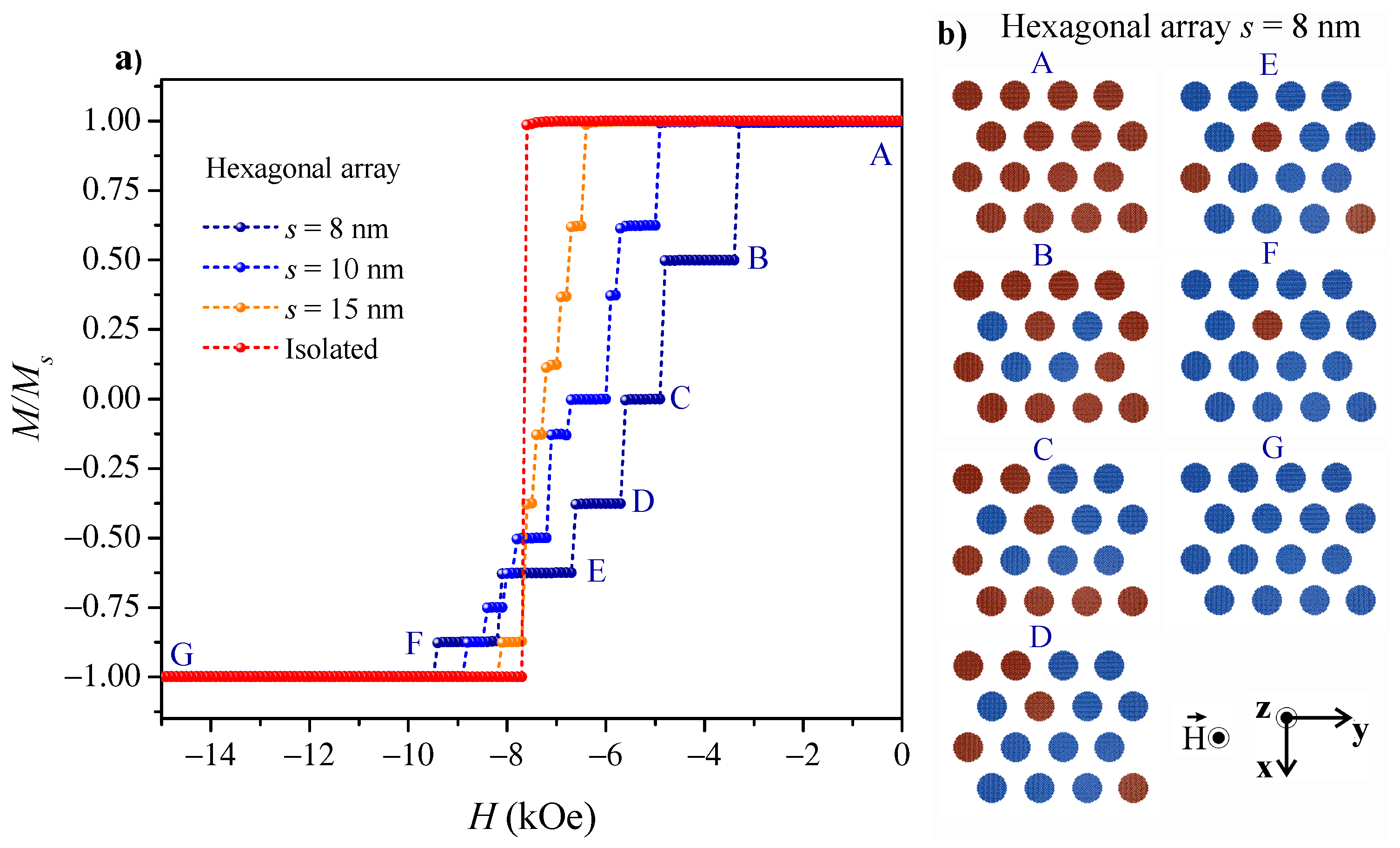
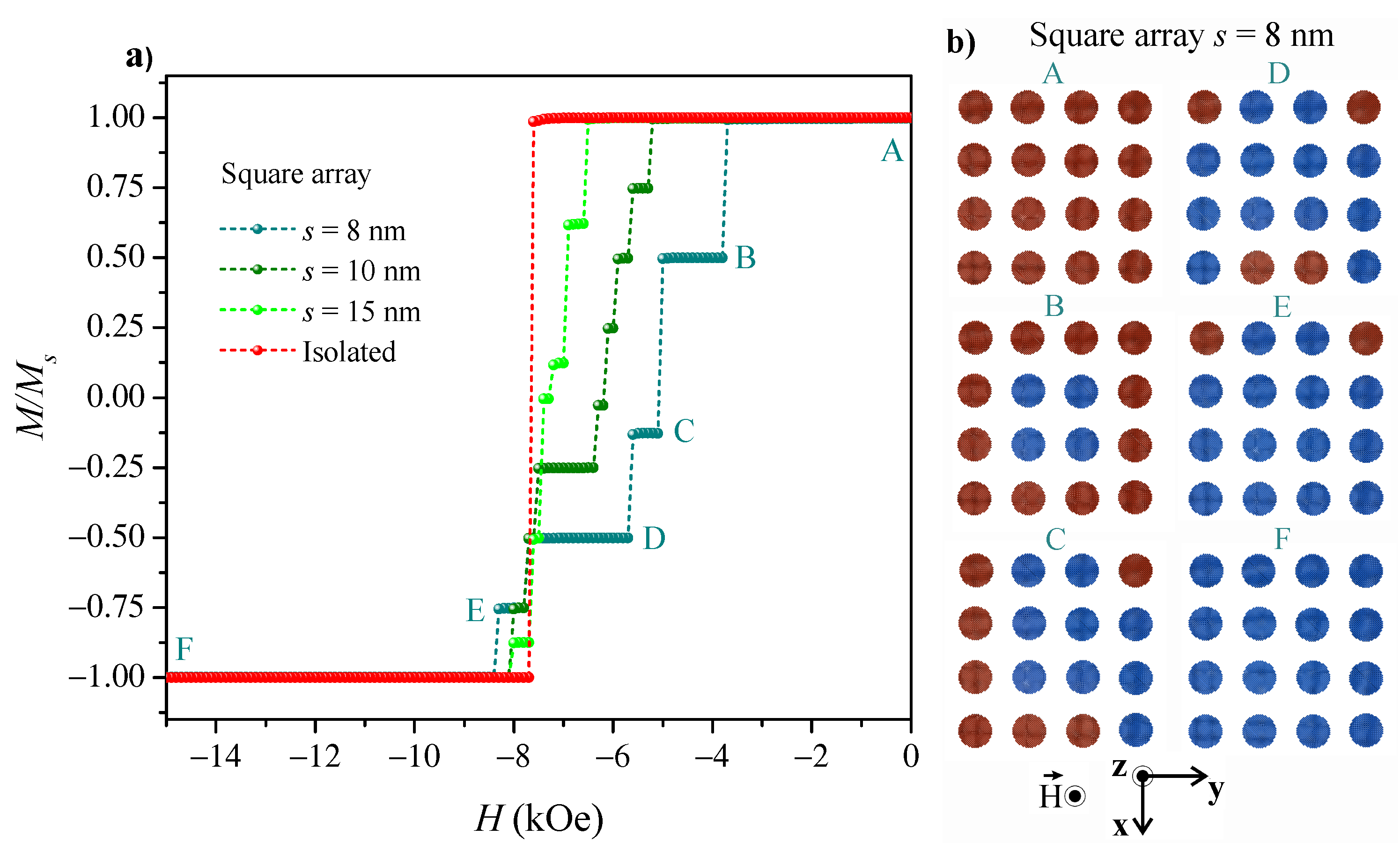
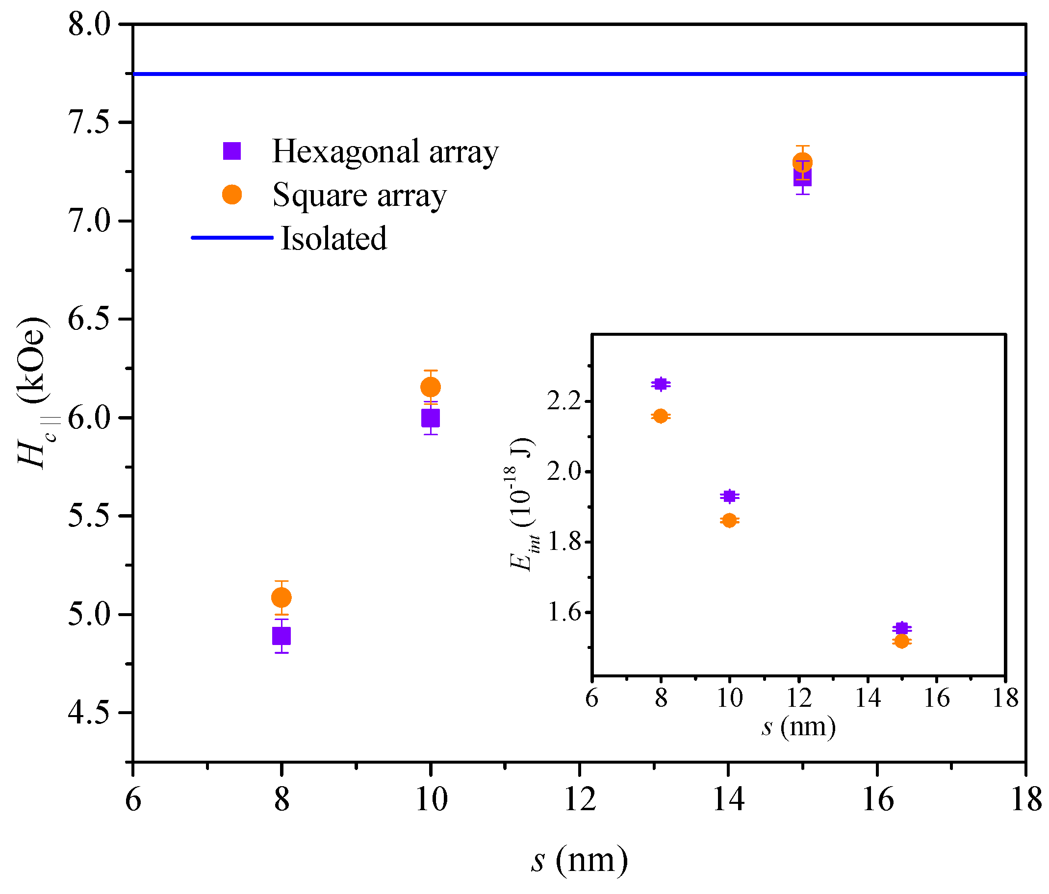
3.2. Arrays of Cylindrical Nanostructures

In the next step of the investigations, calculations of the magnetic properties of the arrays of cylindrical nanostructures were done. We consider here two types of arrays, square and hexagonal, consisting of 16 Fe cylindrical nanostructures (see Figure 1b,c). As atomistic calculations are computationally expensive and time consuming, we chose the value of the aspect ratio for nanostructures in arrays equal to 4 (each cylinder has a diameter of 5 nm and length of 20 nm). Our calculations showed (Figure 3) that starting from this value of aspect ratio the coercivity begins to saturate and the shape anisotropy determines an easy axis of magnetization along the axis of nanowires. The performed calculations will reveal the magnetic interactions between cylindrical nanostructures, which should reflect the real Fe nanowire matrix and show how changes in the distance between such nanostructures (s) affect their magnetic properties. We should note that, as shown in the previous chapter, the reversal mechanism for the isolated nanostructure with this aspect ratio is via coherent rotation.
Figure 5a and Figure 6a represent magnetization curves for the hexagonal and square arrays of Fe cylindrical nanostructures for the different values of the center-to-center distance (s) between them. The only parameter differentiating these curves are dipolar interactions, which reduce the coercivity value. As could be expected, the smallest coercivity was obtained for nanostructures with the shortest distance, which indicates the highest interactions between them. Intuitively, the interactions between wires decreased with increasing distance (s) and the corresponding curve approaches the hysteresis curve for an isolated cylinder. The described behavior was observed in both nanostructures systems. The dependence of the coercive field on the distance s is shown in Figure 7. In addition, the magnetostatic energy of the cylindrical nanostructures array based on the dipole field calculations implemented in VAMPIRE software [39] was obtained after applying saturating field along the long cylinder axis (the inset of Figure 7). The observed decrease in interaction energy with s is correlated with the increase in coercivity for both types of arrays, which indicates the great importance of interaction between cylindrical nanostructures in determining their magnetic properties. This observation is in agreement with previous micromagnetic and atomistic studies of arrays of cylindrical nanostructures, which showed that for a large interwire distance, the coercivity of the nanowire array is close to the coercive field of a single object [23,29,37,65]. It means that at large interwire distances, the dipolar interactions lose their importance and the magnetic behavior is determined by the effective magnetic anisotropy. The decrease in coercivity with the increase in dipolar interactions was also theoretically confirmed for Ni nanowires using the scaling technique combined with Monte Carlo simulations [66]. A similar effect was observed experimentally for densely packed arrays of Ni nanowires [67,68], where the coercive field decreases with an increase in the ratio of diameter to interwire distance as well as for Co [69] and Fe nanowires arrays [32].
As described in the literature, in an isolated nanowire, the shape anisotropy tends to arrange the magnetization vector parallel to the wire axis. In the case of an array of nanowires, the dipolar field, which can switch the easy axis from parallel to perpendicular direction to the wire axis, especially for small interwire distances, should be taken into account [70]. Moreover, the collective demagnetization modes, which leads to a further reduction of the switching field should also be considered [68].
Another interesting point in the magnetic behavior of nanostructure arrays is connected with the appearance of steps on the hysteresis curve, related to the Barkhausen effect [71]. Such behavior is explained by the finite size of the arrays limited to a few nanowires, for which the remagnetization process of the entire system is done by reversal of each individual wire in the array [23,28,29]. Similar behavior is also observed in our case for the arrays consisting of 16 cylindrical nanostructures, for both types of arrangement (Figure 5a and Figure 6a). As can be seen, the steps with well-visible plateaux in the hysteresis curve are observed for the smallest distance between objects, while with increasing distance between the cylinders they become less distinct. The increase in the interaction between cylindrical nanoobjects with the decrease in the distance s results in less squared and more oblique-shaped hysteresis. The same effect was observed experimentally for the arrays consisting of several wires (over a micrometer range of diameters) [22,71]. However, for large nanowire arrays, which are typical systems in experimental measurements, hysteresis curves have no visible steps and become less squared as the packing factor increases [32,68,69].
In order to better understand the origin of step-like behavior observed for the arrays of nanostructures, an analysis of the magnetization reversal mechanism and spin orientations process was performed at each step of the field change. Let us look at the spin configurations for the case of the hexagonal array with s = 8 nm (Figure 5b), for which, as mentioned above, the steps are the most pronounced.
The remagnetization process starts with configuration A in Figure 5b, when all the spins in the cylinders are aligned in the same direction (the system is saturated along the Oz direction). The magnetization switching of the whole array takes place in several stages, each connected with the magnetization reversal of one or a few nanowires along the -Oz direction. The reorientation of spins starts from the cylinders which are placed inside the array and have the highest number of nearest neighbors. This is due to the stronger impact of the demagnetizing field of the neighboring nanostructures on them. This stage is assigned to configuration B and is preceded by a sharp drop in magnetization observed in the M ( H ) curve. The following magnetization state with the plateau region is observed when the same number of cylinders are magnetized parallel to the field and opposite to it (see spin configuration C in Figure 5b). A state in which exactly half of the nanostructures have magnetic moments in the same direction as the applied field and half of them in the opposite direction is favorable since the magnetostatic energy is minimized in this case. As the field continues to increase, the rotation of the spins in the remaining cylinders starts to reorient in direction of the applied field and the magnetization curve goes through a few more steps (configurations from D to F) until the system is saturated along the -Oz direction (configuration G). A similar scenario of magnetization switching is observed for the arrays with larger distances between cylindrical nanostructures, however, due to the smaller interaction between objects, the Barkhausen steps on the corresponding M ( H ) curves are less pronounced.
In the case of square arrays of cylindrical nanostructures (Figure 6b), the remagnetization process starts from the saturation of all cylinders in the Oz direction (see configuration A), similarly, as for hexagonal matrices. And as with the hexagonal system, the spin reorientation begins from the cylinders that have the greatest number of nearest neighbors (configuration B). The plateau on the M ( H ) curve is observed at the same magnetization value as in the case of hexagonal array. A further increase in the field value causes a gradual remagnetization of the remaining cylinders, placed at the edges of the array. Finally, the system goes to the spin configuration F, with all the nanostructures saturated along -Oz direction. A similar remagnetization scenario is observed for the cylinders with larger distances (s) in square systems. It should be noted that the slight difference in the magnetization reversal process for the two types of arrays can be explained by the different strengths of interactions between nanostructures. Due to the close packing of nanostructures in a hexagonal array, the interactions of an individual cylinder with others in such an array are more significant. One of the main factors, which affect remagnetization behavior is the number of nearest neighbors surrounding the nanowire [28]. In the case of square array the particular cylinder has smaller number of adjacent objects, however, there are also next nearest neighbors. As a result, the farther away the cylinders are placed from each other, the higher the applied field values are needed to reorient their magnetization. Therefore, different magnetic behavior could be observed for the square and hexagonal arrays of cylindrical nanostructures.
As we have noted, a frozen magnetization states appear when a part of nanostructures is magnetized parallel and part—antiparallel to the field direction. In this case, the dipolar field created by the switched nanostructures hinders the switching of the remaining nanostructures and such a state can be held for a certain range of field changes. The existence of such a states was observed experimentally by magnetic force microscopy in the study of Ni nanopillar arrays [68,72]. It has been shown that when the adjacent objects have antiparallel magnetization directions, the magnetostatic energy of the sample is minimized. Thus, such an intermediated state can be held for a wide range of changes in the magnetic field, which is in accordance with performed calculations. Also, the studies of iron nanowire arrays using first-order reversal curves analysis have demonstrated that a similar inhomogeneous state arises in the arrays during the remagnetization process when some nanowires are magnetized antiparallel to each other [33].
An interesting observation can be made by quantitative analysis of the remagnetization process for certain distances between cylindrical nanostructures in hexagonal and square arrays. As shown in Figure 7, the difference in coercivity in hexagonal and square arrays is the most significant for cylindrical nanostructures with the shortest nanowire distances (with s = 8 nm), when the interaction energy between neighboring objects is the highest (see inset of Figure 7), while it becomes negligible for larger distances between them, as the interactions between nanostructures weaken. This indicates that the total interaction energy between nanostructures is greater in the case of the hexagonal array compared to the square system. Such an observation can be explained by a different number of the neighboring structures in both types of arrays (Figure 1): in a square array the central object has four nearest neighbors at a distance s and four next nearest neighbors at a distance 2 s , while in a hexagonal array, all six nearest neighboring wires are at a distance s. In this case, especially for small values of s, interactions with more distant neighbors must be taken into account in addition to the interactions between the nearest neighbors [73]. Furthermore, the areal filling fraction of arrays is different for square and hexagonal systems. As shown, the corresponding value is almost 15% higher in the case of a hexagonal array [74], which means the greater packing of nanowires and, consequently, stronger interactions between them. It can also be seen that magnetostatic energy between cylinders in the hexagonal array is notably higher for smaller distances s in comparison to the square array, which is in accordance with the higher packing of nanoobjects in the hexagonal array.
It should be noted that the calculated values of the coercive field for the arrays of cylindrical iron nanostructures correspond to the zero temperature limit. Based on the applied atomistic model, thermal effects can be included in the simulations by using Langevin dynamics and introducing the effective thermal field into the LLG equation [39]. As was shown in previous theoretical research for similar nanostructures [44,75], the reduction of the coercive field is observed with the increase of temperature as a result of increasing oscillations of spins in the material caused by the thermal field. We can expect the same effect in the investigated samples, however, such a study goes beyond the conducted research.
Therefore, as we have shown, the applied atomistic simulations can be an effective tool for characterizing the magnetic properties and magnetization switching processes of isolated magnetic cylindrical nanostructures and their arrays. Additionally, the higher number of nanowires in the array could be considered (or periodic boundary conditions applied) to obtain the better correlation with the experimental data, where usually the infinite number of nanowires is investigated. In this case, a much greater influence of the dipolar field on the shape of the hysteresis loop should be visible [23]. Let us note, that performed calculations for the systems of very small (d = 5 nm) iron nanostructures can be of great interest also from an experimental point of view. The significant number of publications shows the possibility of implementing ferromagnetic nanowires for nanotechnological applications (e.g., magnetic memory units, sensors, etc.) and the tendency for miniaturization of such devices grows yearly. The synthesis process of considered arrays of nanowires with a diameter of about 5 nm could be done e.g., using the SBA-15 or MCM-41 mesoporous silica matrices or anodic-aluminum oxide/mesoporous-silica composites as a template [76,77]. Such materials possess highly ordered hexagonally arranged pores of a few nanometer diameters and have a possibility of tuning structural parameters [6], which allows to use it as a host matrix for fabricating magnetic nanowires able to show new interesting magnetic properties and quantum size effects.

4. Conclusions

The magnetic behavior of iron cylindrical nanostructures was analyzed by using atomistic spin model calculations. As was shown, for the isolated nanostructures with a diameter of 5 nm, the coercive field strongly depends on the aspect ratio value and applied field direction. For the case of disclike h / d < 1 and elongated h / d > 1 objects, the shape anisotropy determines the easy axis of magnetization, and magnetic behavior can be correlated with the change of demagnetization factors for corresponding geometry. The analysis of spin reversal mechanisms revealed the existence of two different modes depending on the length of the nanowire: coherent rotation for h / d < 10 and transverse domain wall propagation for h / d 10. The studies of the magnetic behavior of arrays of cylindrical nanostructures with h / d = 4 have shown that total interaction energy between objects is greater in the case of a hexagonal arrangement than for a square system, which is explained by a different number of neighboring wires in both types of arrays. With a decrease in the interwire distance, the less squared shape of the M ( H ) curves was observed with multiple Barkhausen steps. The detailed analysis of spin configurations during the remagnetization process has shown the formation of intermediate magnetization states with antiparallel magnetization orientation of some of the neighboring nanostructures in arrays during the remagnetization process, which correspond to the observed steps on the M ( H ) curves. The obtained results may be useful for a better understanding of the experimentally observed behavior of iron nanowires arrays and further theoretical investigations of similar magnetic nanostructures.

Author Contributions

Conceptualization, O.P. and M.K. (Malgorzata Kac); methodology, O.P. and M.K. (Malgorzata Kac); investigation, O.P., M.K. (Malgorzata Kac), S.P. and D.K.; visualization, O.P. and S.P.; validation, M.K. (Malgorzata Kac), D.K., M.Z., M.K. (Maciej Krawczyk) and Ł.L.; project administration, O.P.; formal analysis, S.P., D.K., M.Z. and M.K. (Maciej Krawczyk); writing—original draft preparation, O.P. and M.K. (Malgorzata Kac); writing—review and editing, M.K. (Malgorzata Kac), S.P., D.K., M.Z., M.K. (Maciej Krawczyk) and Ł.L.; supervision, M.K. (Malgorzata Kac) and Ł.L. All authors have read and agreed to the published version of the manuscript.

Funding

The authors are grateful to the National Science Centre, Poland for financial support for this investigation (Grant No. 2017/26/E/ST5/00162). The numerical calculations were performed at Poznan Supercomputing and Networking Center (Grant No. 424).

Institutional Review Board Statement

Not applicable.

Informed Consent Statement

Not applicable.

Data Availability Statement

Data will be made available on request.

Acknowledgments

The authors would like to thank Stefan Stagraczyński (Institute of Spintronics and Quantum Information, Faculty of Physics, Adam Mickiewicz University) for fruitful discussions and suggestions concerning performed calculations.

Conflicts of Interest

The authors have no competing interest to declare.

References

  1. Krahne, R.; Morello, G.; Figuerola, A.; George, C.; Deka, S.; Manna, L. Physical properties of elongated inorganic nanoparticles. Phys. Rep. 2011, 501, 75–221. [Google Scholar] [CrossRef]
  2. Staňo, M.; Fruchart, O. Magnetic nanowires and nanotubes. In Handbook of Magnetic Materials; Elsevier: Amsterdam, The Netherlands, 2018; Volume 27, pp. 155–267. [Google Scholar] [CrossRef] [Green Version]
  3. Vázquez, M. Magnetic Nano-And Microwires: Design, Synthesis, Properties and Applications; Woodhead Publishing: Soston, UK, 2015; p. 870. [Google Scholar]
  4. Zhang, A.; Zheng, G.; Lieber, C.M. Nanowires: Building Blocks for Nanoscience and Nanotechnology; Springer: Berlin/Heidelberg, Germany, 2017. [Google Scholar]
  5. Zhai, T.; Yao, J. One-Dimensional Nanostructures: Principles and Applications; John Wiley & Sons: Hoboken, NJ, USA, 2012. [Google Scholar]
  6. Laskowski, Ł.; Laskowska, M.; Vila, N.; Schabikowski, M.; Walcarius, A. Mesoporous silica-based materials for electronics-oriented applications. Molecules 2019, 24, 2395. [Google Scholar] [CrossRef] [PubMed] [Green Version]
  7. Laskowski, Ł.; Laskowska, M.; Jelonkiewicz, J.; Piech, H.; Galkowski, T.; Boullanger, A. The concept of molecular neurons. In Proceedings of the International Conference on Artificial Intelligence and Soft Computing, Zakopane, Poland, 12–16 June; Springer: Berlin/Heidelberg, Germany, 2016; pp. 494–501. [Google Scholar] [CrossRef]
  8. Laskowska, M.; Laskowski, Ł.; Jelonkiewicz, J.; Piech, H.; Filutowicz, Z. Porous Silica-Based Optoelectronic Elements as Interconnection Weights in Molecular Neural Networks. In Proceedings of the International Conference on Artificial Intelligence and Soft Computing, Zakopane, Poland, 3–7 June 2018; Springer: Berlin/Heidelberg, Germany, 2018; pp. 130–135. [Google Scholar] [CrossRef]
  9. Walter, E.; Ng, K.; Zach, M.; Penner, R.; Favier, F. Electronic devices from electrodeposited metal nanowires. Microelectron. Eng. 2002, 61, 555–561. [Google Scholar] [CrossRef]
  10. Wanekaya, A.K.; Chen, W.; Myung, N.V.; Mulchandani, A. Nanowire-based electrochemical biosensors. Electroanalysis 2006, 18, 533–550. [Google Scholar] [CrossRef]
  11. Kartopu, G.; Yalçın, O.; Lupu, N. Fabrication and applications of metal nanowire arrays electrodeposited in ordered porous templates. In Electrodeposited Nanowires and Their Applications; Books on Demand: Norderstedt, Germany, 2010; p. 228. [Google Scholar] [CrossRef] [Green Version]
  12. Kumeria, T.; Maher, S.; Wang, Y.; Kaur, G.; Wang, L.; Erkelens, M.; Forward, P.; Lambert, M.F.; Evdokiou, A.; Losic, D. Naturally derived Iron oxide nanowires from Bacteria for magnetically triggered drug release and Cancer hyperthermia in 2D and 3D culture environments: Bacteria biofilm to potent Cancer therapeutic. Biomacromolecules 2016, 17, 2726–2736. [Google Scholar] [CrossRef]
  13. Peixoto, L.; Magalhães, R.; Navas, D.; Moraes, S.; Redondo, C.; Morales, R.; Araújo, J.; Sousa, C. Magnetic nanostructures for emerging biomedical applications. Appl. Phys. Rev. 2020, 7, 011310. [Google Scholar] [CrossRef]
  14. Sugumaran, P.J.; Yang, Y.; Wang, Y.; Liu, X.; Ding, J. Influence of the Aspect Ratio of Iron Oxide Nanorods on Hysteresis-Loss-Mediated Magnetic Hyperthermia. ACS Appl. Bio Mater. 2021, 4, 4809–4820. [Google Scholar] [CrossRef]
  15. Yang, S.; Zhu, H.; Yu, D.; Jin, Z.; Tang, S.; Du, Y. Preparation and magnetic property of Fe nanowire array. J. Magn. Magn. Mater. 2000, 222, 97–100. [Google Scholar] [CrossRef]
  16. Prida, V.; García, J.; Hernando, B.; Bran, C.; Vivas, L.; Vázquez, M. Electrochemical synthesis of magnetic nanowires with controlled geometry and magnetic anisotropy. In Magnetic Nano- and Microwires; Elsevier: Berlin/Heidelberg, Germany, 2015; pp. 41–104. [Google Scholar] [CrossRef]
  17. Hurst, S.J.; Payne, E.K.; Qin, L.; Mirkin, C.A. Multisegmented one-dimensional nanorods prepared by hard-template synthetic methods. Angew. Chem. Int. Ed. 2006, 45, 2672–2692. [Google Scholar] [CrossRef]
  18. Napolsky, K.; Eliseev, A.; Knotko, A.; Lukahsin, A.; Vertegel, A.; Tretyakov, Y.D. Preparation of ordered magnetic iron nanowires in the mesoporous silica matrix. Mater. Sci. Eng. C 2003, 23, 151–154. [Google Scholar] [CrossRef]
  19. Whitney, T.; Searson, P.; Jiang, J.; Chien, C. Fabrication and magnetic properties of arrays of metallic nanowires. Science 1993, 261, 1316–1319. [Google Scholar] [CrossRef]
  20. Seley, D.B.; Dissing, D.A.; Sumant, A.V.; Divan, R.; Miller, S.; Auciello, O.; Lepak, L.A.; Terrell, E.A.; Shogren, T.J.; Fahrner, D.A.; et al. Electroplate and lift lithography for patterned micro/nanowires using ultrananocrystalline diamond (UNCD) as a reusable template. ACS Appl. Mater. Interfaces 2011, 3, 925–930. [Google Scholar] [CrossRef]
  21. Yuan, J.; Xu, Y.; Müller, A.H. One-dimensional magnetic inorganic—Organic hybrid nanomaterials. Chem. Soc. Rev. 2011, 40, 640–655. [Google Scholar] [CrossRef]
  22. Sampaio, L.; Sinnecker, E.; Cernicchiaro, G.; Knobel, M.; Vázquez, M.; Velázquez, J. Magnetic microwires as macrospins in a long-range dipole-dipole interaction. Phys. Rev. B 2000, 61, 8976. [Google Scholar] [CrossRef] [Green Version]
  23. Zighem, F.; Maurer, T.; Ott, F.; Chaboussant, G. Dipolar interactions in arrays of ferromagnetic nanowires: A micromagnetic study. J. Appl. Phys. 2011, 109, 013910. [Google Scholar] [CrossRef]
  24. Kac, M.; Nykiel, A.; Pastukh, O.; Kopec, M.; Zarzycki, A.; Maximenko, A.; Parlinska-Wojtan, M.; Dutkiewicz, E.; Kopia, A. The role of the addition of Cu in alloyed and multilayered Fe-based nanowires. Mater. Sci. Eng. B 2022, 281, 115732. [Google Scholar] [CrossRef]
  25. Proenca, M.P.; Rial, J.; Araujo, J.P.; Sousa, C.T. Magnetic reversal modes in cylindrical nanostructures: From disks to wires. Sci. Rep. 2021, 11, 10100. [Google Scholar] [CrossRef] [PubMed]
  26. Nguyen, T.; Cottam, M.; Liu, H.; Wang, Z.; Ng, S.; Kuok, M.; Lockwood, D.; Nielsch, K.; Gösele, U. Spin waves in permalloy nanowires: The importance of easy-plane anisotropy. Phys. Rev. B 2006, 73, 140402. [Google Scholar] [CrossRef] [Green Version]
  27. Ivanov, Y.; Chubykalo-Fesenko, O. Micromagnetic simulations of cylindrical magnetic nanowires. In Magnetic Nano- and Microwires; Vázquez, M., Ed.; Woodhead Publishing: Soston, UK, 2015; pp. 423–448. [Google Scholar] [CrossRef] [Green Version]
  28. David, C.; Kappel, W.; Pătroi, E.A.; Manta, E.; Midoi, V. Micromagnetic study of iron nanowire arrays. Rev. Roum. Sci. Tech. 2022, 1, 9–13. [Google Scholar]
  29. Wen-Bing, C.; Man-Gui, H.; Hao, Z.; Yu, O.; Long-Jiang, D. Micromagnetic simulation on the dynamic susceptibility spectra of cobalt nanowires arrays: The effect of magnetostatic interaction. Chin. Phys. B 2010, 19, 087502. [Google Scholar] [CrossRef]
  30. Moraes, S.; Navas, D.; Béron, F.; Proenca, M.P.; Pirota, K.R.; Sousa, C.T.; Araújo, J.P. The role of Cu length on the magnetic behaviour of Fe/Cu multi-segmented nanowires. Nanomaterials 2018, 8, 490. [Google Scholar] [CrossRef] [PubMed] [Green Version]
  31. Silvani, R.; Kostylev, M.; Adeyeye, A.O.; Gubbiotti, G. Spin wave filtering and guiding in Permalloy/iron nanowires. J. Magn. Magn. Mater. 2018, 450, 51–59. [Google Scholar] [CrossRef]
  32. Dubitskiy, I.; Elmekawy, A.; Iashina, E.; Sotnichuk, S.; Napolskii, K.; Menzel, D.; Mistonov, A. Effect of interactions and non-uniform magnetic states on the magnetization reversal of iron nanowire arrays. J. Supercond. Nov. Magn. 2021, 34, 539–549. [Google Scholar] [CrossRef]
  33. Elmekawy, A.; Iashina, E.; Dubitskiy, I.; Sotnichuk, S.; Bozhev, I.; Napolskii, K.S.; Menzel, D.; Mistonov, A. Magnetic properties and FORC analysis of iron nanowire arrays. Mater. Today Commun. 2020, 25, 101609. [Google Scholar] [CrossRef]
  34. Neetzel, C.; Kamimura, H.; Hayashida, M.; Ohgai, T. Uniaxial magnetization reversal process in electrodeposited high-density iron nanowire arrays with ultra-large aspect ratio. Results Phys. 2019, 15, 102653. [Google Scholar] [CrossRef]
  35. Forster, H.; Schrefl, T.; Scholz, W.; Suess, D.; Tsiantos, V.; Fidler, J. Micromagnetic simulation of domain wall motion in magnetic nano-wires. J. Magn. Magn. Mater. 2002, 249, 181–186. [Google Scholar] [CrossRef]
  36. Hertel, R.; Kirschner, J. Magnetization reversal dynamics in nickel nanowires. Phys. B Condens. Matter 2004, 343, 206–210. [Google Scholar] [CrossRef]
  37. Agramunt-Puig, S.; Del-Valle, N.; Pellicer, E.; Zhang, J.; Nogués, J.; Navau, C.; Sanchez, A.; Sort, J. Modeling the collective magnetic behavior of highly-packed arrays of multi-segmented nanowires. New J. Phys. 2016, 18, 013026. [Google Scholar] [CrossRef]
  38. Leliaert, J.; Dvornik, M.; Mulkers, J.; De Clercq, J.; Milošević, M.; Van Waeyenberge, B. Fast micromagnetic simulations on gpu—recent advances made with. J. Phys. D Appl. Phys. 2018, 51, 123002. [Google Scholar] [CrossRef]
  39. Evans, R.F.; Fan, W.J.; Chureemart, P.; Ostler, T.A.; Ellis, M.O.; Chantrell, R.W. Atomistic spin model simulations of magnetic nanomaterials. J. Phys. Condens. Matter 2014, 26, 103202. [Google Scholar] [CrossRef]
  40. Hovorka, O.; Devos, S.; Coopman, Q.; Fan, W.; Aas, C.; Evans, R.; Chen, X.; Ju, G.; Chantrell, R. The Curie temperature distribution of FePt granular magnetic recording media. Appl. Phys. Lett. 2012, 101, 052406. [Google Scholar] [CrossRef]
  41. Liao, J.W.; Atxitia, U.; Evans, R.F.; Chantrell, R.W.; Lai, C.H. Atomistic modeling of magnetization reversal modes in L10 FePt nanodots with magnetically soft edges. Phys. Rev. B 2014, 90, 174415. [Google Scholar] [CrossRef] [Green Version]
  42. Meo, A.; Chureemart, P.; Wang, S.; Chepulskyy, R.; Apalkov, D.; Chantrell, R.W.; Evans, R.F. Thermally nucleated magnetic reversal in CoFeB/MgO nanodots. Sci. Rep. 2017, 7, 16729. [Google Scholar] [CrossRef] [Green Version]
  43. Meo, A.; Chepulskyy, R.; Apalkov, D.; Chantrell, R.W.; Evans, R.F. Atomistic investigation of the temperature and size dependence of the energy barrier of CoFeB/MgO nanodots. J. Appl. Phys. 2020, 128, 073905. [Google Scholar] [CrossRef]
  44. Ramos-Guivar, J.A.; Tamanaha-Vegas, C.A.; Litterst, F.J.; Passamani, E.C. Magnetic simulations of core–shell ferromagnetic bi-magnetic nanoparticles: The influence of antiferromagnetic interfacial exchange. Nanomaterials 2021, 11, 1381. [Google Scholar] [CrossRef] [PubMed]
  45. Moreno, R.; Poyser, S.; Meilak, D.; Meo, A.; Jenkins, S.; Lazarov, V.K.; Vallejo-Fernandez, G.; Majetich, S.; Evans, R.F. The role of faceting and elongation on the magnetic anisotropy of magnetite Fe3O4 nanocrystals. Sci. Rep. 2020, 10, 2722. [Google Scholar] [CrossRef] [PubMed] [Green Version]
  46. Gao, J.H.; Sun, D.L.; Zhan, Q.F.; He, W.; Cheng, Z.H. Magnetization reversal process and magnetic relaxation of self-assembled Fe3Pt nanowire arrays with different diameters: Experiment and micromagnetic simulations. Phys. Rev. B 2007, 75, 064421. [Google Scholar] [CrossRef] [Green Version]
  47. Hertel, R. Micromagnetic simulations of magnetostatically coupled nickel nanowires. J. Appl. Phys. 2001, 90, 5752–5758. [Google Scholar] [CrossRef] [Green Version]
  48. Momma, K.; Izumi, F. VESTA 3 for three-dimensional visualization of crystal, volumetric and morphology data. J. Appl. Crystallogr. 2011, 44, 1272–1276. [Google Scholar] [CrossRef]
  49. García-Palacios, J.L.; Lázaro, F.J. Langevin-dynamics study of the dynamical properties of small magnetic particles. Phys. Rev. B 1998, 58, 14937. [Google Scholar] [CrossRef] [Green Version]
  50. Sellmyer, D.; Zheng, M.; Skomski, R. Magnetism of Fe, Co and Ni nanowires in self-assembled arrays. J. Phys. Condens. Matter 2001, 13, R433. [Google Scholar] [CrossRef]
  51. Abo, G.S.; Hong, Y.K.; Park, J.; Lee, J.; Lee, W.; Choi, B.C. Definition of magnetic exchange length. IEEE Trans. Magn. 2013, 49, 4937–4939. [Google Scholar] [CrossRef]
  52. Paulus, P.; Luis, F.; Kröll, M.; Schmid, G.; De Jongh, L. Low-temperature study of the magnetization reversal and magnetic anisotropy of Fe, Ni, and Co nanowires. J. Magn. Magn. Mater. 2001, 224, 180–196. [Google Scholar] [CrossRef]
  53. Sun, L.; Hao, Y.; Chien, C.L.; Searson, P.C. Tuning the properties of magnetic nanowires. IBM J. Res. Dev. 2005, 49, 79–102. [Google Scholar] [CrossRef]
  54. Ramazani, A.; Ghaffari, M.; Kashi, M.A.; Kheiry, F.; Eghbal, F. A new approach to fabricating magnetic multilayer nanowires by modifying the ac pulse electrodeposition in a single bath. J. Phys. D Appl. Phys. 2014, 47, 355003. [Google Scholar] [CrossRef]
  55. Tang, X.T.; Wang, G.C.; Shima, M. Magnetic layer thickness dependence of magnetization reversal in electrodeposited CoNi/Cu multilayer nanowires. J. Magn. Magn. Mater. 2007, 309, 188–196. [Google Scholar] [CrossRef]
  56. Chen, M.; Chien, C.L.; Searson, P.C. Potential modulated multilayer deposition of multisegment Cu/Ni nanowires with tunable magnetic properties. Chem. Mater. 2006, 18, 1595–1601. [Google Scholar] [CrossRef]
  57. Medina, J.D.L.T.; Darques, M.; Blon, T.; Piraux, L.; Encinas, A. Effects of layering on the magnetostatic interactions in microstructures of CoxCu1−x/Cu nanowires. Phys. Rev. B 2008, 77, 014417. [Google Scholar] [CrossRef] [Green Version]
  58. Li, F.; Metzger, R.M. Activation volume of α-Fe particles in alumite films. J. Appl. Phys. 1997, 81, 3806–3808. [Google Scholar] [CrossRef]
  59. Xu, H.; Wu, Q.; Yue, M.; Li, C.; Li, H.; Palaka, S. Effect of size distribution on magnetic properties in cobalt nanowires. AIP Adv. 2018, 8, 056422. [Google Scholar] [CrossRef] [Green Version]
  60. Ivanov, Y.P.; Vázquez, M.; Chubykalo-Fesenko, O. Magnetic reversal modes in cylindrical nanowires. J. Phys. D Appl. Phys. 2013, 46, 485001. [Google Scholar] [CrossRef] [Green Version]
  61. Nedelkoski, Z.; Kepaptsoglou, D.; Lari, L.; Wen, T.; Booth, R.A.; Oberdick, S.D.; Galindo, P.L.; Ramasse, Q.M.; Evans, R.F.; Majetich, S.; et al. Origin of reduced magnetization and domain formation in small magnetite nanoparticles. Sci. Rep. 2017, 7, 45997. [Google Scholar] [CrossRef] [Green Version]
  62. Yang, Z.; Chen, Y.; Liu, W.; Wang, Y.; Li, Y.; Zhang, D.; Lu, Q.; Wu, Q.; Zhang, H.; Yue, M. Effects of Shape Anisotropy on Hard–Soft Exchange-Coupled Permanent Magnets. Nanomaterials 2022, 12, 1261. [Google Scholar] [CrossRef] [PubMed]
  63. Pousthomis, M.; Anagnostopoulou, E.; Panagiotopoulos, I.; Boubekri, R.; Fang, W.; Ott, F.; Atmane, K.A.; Piquemal, J.Y.; Lacroix, L.M.; Viau, G. Localized magnetization reversal processes in cobalt nanorods with different aspect ratios. Nano Res. 2015, 8, 2231–2241. [Google Scholar] [CrossRef]
  64. Ramazani, A.; Kashi, M.A.; Ghanbari, S.; Eshaghi, F. Dual behaviors of magnetic CoxFe1−x (0 ≤ x ≤ 1) nanowires embedded in nanoporous with different diameters. J. Magn. Magn. Mater. 2012, 324, 3193–3198. [Google Scholar] [CrossRef]
  65. Ochoa, A.; Mejía-López, J.; Velásquez, E.; Mazo-Zuluaga, J. Finite-length Fe nanowire arrays: The effects of magnetic anisotropy energy, dipolar interaction and system size on their magnetic properties. J. Phys. D Appl. Phys. 2017, 50, 095003. [Google Scholar] [CrossRef]
  66. Bahiana, M.; Amaral, F.; Allende, S.; Altbir, D. Reversal modes in arrays of interacting magnetic Ni nanowires: Monte Carlo simulations and scaling technique. Phys. Rev. B 2006, 74, 174412. [Google Scholar] [CrossRef] [Green Version]
  67. Vázquez, M.; Pirota, K.; Hernández-Vélez, M.; Prida, V.; Navas, D.; Sanz, R.; Batallán, F.; Velázquez, J. Magnetic properties of densely packed arrays of Ni nanowires as a function of their diameter and lattice parameter. J. Appl. Phys. 2004, 95, 6642–6644. [Google Scholar] [CrossRef] [Green Version]
  68. Nielsch, K.; Wehrspohn, R.; Barthel, J.; Kirschner, J.; Gösele, U.; Fischer, S.; Kronmüller, H. Hexagonally ordered 100 nm period nickel nanowire arrays. Appl. Phys. Lett. 2001, 79, 1360–1362. [Google Scholar] [CrossRef] [Green Version]
  69. Kartopu, G.; Yalçın, O.; Es-Souni, M.; Başaran, A. Magnetization behavior of ordered and high density Co nanowire arrays with varying aspect ratio. J. Appl. Phys. 2008, 103, 093915. [Google Scholar] [CrossRef] [Green Version]
  70. Encinas-Oropesa, A.; Demand, M.; Piraux, L.; Huynen, I.; Ebels, U. Dipolar interactions in arrays of nickel nanowires studied by ferromagnetic resonance. Phys. Rev. B 2001, 63, 104415. [Google Scholar] [CrossRef]
  71. Velázquez, J.; Garcıa, C.; Vazquez, M.; Hernando, A. Interacting amorphous ferromagnetic wires: A complex system. J. Appl. Phys. 1999, 85, 2768–2774. [Google Scholar] [CrossRef]
  72. Hwang, M.; Abraham, M.; Savas, T.; Smith, H.I.; Ram, R.J.; Ross, C. Magnetic force microscopy study of interactions in 100 nm period nanomagnet arrays. J. Appl. Phys. 2000, 87, 5108–5110. [Google Scholar] [CrossRef]
  73. Clime, L.; Ciureanu, P.; Yelon, A. Magnetostatic interactions in dense nanowire arrays. J. Magn. Magn. Mater. 2006, 297, 60–70. [Google Scholar] [CrossRef]
  74. Cabria, I.; Prida, V. Magnetostatic dipolar anisotropy energy and anisotropy constants in arrays of ferromagnetic nanowires as a function of their radius and interwall distance. J. Phys. Commun. 2020, 4, 035015. [Google Scholar] [CrossRef] [Green Version]
  75. Aurélio, D.; Vejpravova, J. Understanding magnetization dynamics of a magnetic nanoparticle with a disordered shell using micromagnetic simulations. Nanomaterials 2020, 10, 1149. [Google Scholar] [CrossRef] [PubMed]
  76. El-Sheikh, S.M.; Harraz, F.A.; Hessien, M.M. Magnetic behavior of cobalt ferrite nanowires prepared by template-assisted technique. Mater. Chem. Phys. 2010, 123, 254–259. [Google Scholar] [CrossRef]
  77. Ji, G.; Gong, Z.; Liu, Y.; Chang, X.; Du, Y.; Qamar, M. Fabrication and magnetic properties of cobalt nanorod arrays containing a number of ultrafine nanowires electrodeposited within an AAO/SBA-15 template. Solid State Commun. 2011, 151, 1151–1155. [Google Scholar] [CrossRef]
Figure 1. Graphical visualization of the investigated structures used in the calculations: (a) single cylindrical nanostructure (the magnification shows packing arrangement of atoms in considered bcc iron structure), (b) hexagonal arrangement of nanostructures and (c) square arrangement of nanostructures. The wire axis for all structures is along O z direction. The notation means as follows: d is the diameter of nanowires, h is the length of nanowires and s is center-to-center distance between neighboring nanowires. All structures were rendered using VESTA software [48].
Crystals 13 00537 g001
Figure 2. Calculated hysteresis loops of the isolated iron cylindrical nanostructures with a magnetic field applied parallel (pink) and perpendicular (dark blue) to the direction determined by the axis of the nanoobjects (h parameter). The following values of aspect ratio h / d were adopted: 0.6 (a), 1 (b) (inset: M ( H ) loops for Fe nanostructure with a cube shape), 2 (c), 4 (d), 10 (e) and 20 (f).
Crystals 13 00537 g002
Figure 3. Coercive field for cylindrical nanostructures for the parallel and perpendicular orientation of the magnetic field as a function of the aspect ratio (inset: dependence of demagnetization factor values on the aspect ratio).
Crystals 13 00537 g003
Figure 4. Snapshots of the spin configurations of a single cylindrical nanostructure with the aspect ratio h / d = 5 (a) and h / d = 10 (b) for a magnetic field applied in a parallel direction to the object axis, showing two different spin reversal modes, characteristic of h / d < 10 and h / d 10. The color changes with the projection of the spin along the direction of the external field. The boundary cases correspond to pure red and pure blue colors for the spins aligned along the nanostructures axis, in up and down directions, while white colors mean spins aligned perpendicular to the axis of cylindrical nanostructures.
Crystals 13 00537 g004
Figure 5. Hysteresis curves for hexagonal arrays of Fe cylindrical nanostructures with the aspect ratio h / d = 4, calculated for different distances between them (a). For comparison, a hysteresis loop was added for an isolated cylindrical nanostructure with the same aspect ratio. A cross-section through the top of the cylindrical nanostructures in hexagonal array ( h / d = 4 ) with distance s = 8 nm, showing the corresponding spin configurations during the remagnetization process (b). The configurations A and G correspond to saturation along Oz (red color) and -Oz (blue color) field direction, respectively, while configurations from B to F correspond to the intermediate magnetization states (see the text). All configurations are indicated on the corresponding M ( H ) curve.
Crystals 13 00537 g005
Figure 6. Hysteresis curves for square arrays of Fe cylindrical nanostructures with the aspect ratio h / d = 4, calculated for different distances between them (a) and a cross-section through the top of the cylindrical nanostructures in square array ( h / d = 4 ) with distance s = 8 nm, showing the corresponding spin configurations during the remagnetization process (b). The configurations A and F correspond to saturation along Oz (red color) and -Oz (blue color) field direction, respectively, while configurations from B to E correspond to the intermediate magnetization states (see the text). All configurations are indicated on the corresponding M ( H ) curve.
Crystals 13 00537 g006
Figure 7. The dependence of coercive field for square and hexagonal arrays of Fe cylindrical nanostructures on the distance between them. The dash horizontal line represents the coercive field value for an isolated cylinder. The inset shows the dependence of magnetostatic interaction energy on the distance between nanostructures in square and hexagonal arrays.
Crystals 13 00537 g007
Table 1. The values of coercive field and demagnetization coefficients (for the magnetic field applied parallel and perpendicular to the main axis of nanoobjects) for cylindrical nanostructures as a function of aspect ratio.
h (nm)Aspect RatioNumber of Atoms H c kOe N d H c kOe N d
30.650500.0440.496
5184171.0410.330680.36670.33466
102168535.2450.173560.004860.41322
153248316.8430.108710.004190.44565
204331107.6460.075410.003910.46230
255420878.0530.055820.003640.47209
5010839348.7490.020290.003020.48986
75151239268.8260.010750.002630.49463
100201678798.8440.006750.002270.49663
Disclaimer/Publisher’s Note: The statements, opinions and data contained in all publications are solely those of the individual author(s) and contributor(s) and not of MDPI and/or the editor(s). MDPI and/or the editor(s) disclaim responsibility for any injury to people or property resulting from any ideas, methods, instructions or products referred to in the content.

