1. Introduction
Due to the service conditions in gas turbines, first for military applications and more and more for commercial applications, turbine blade materials have received enormous amounts of interest for use both in jet engines and industrial gas turbines. Over the decades, these have evolved into highly engineered components made of a single crystal of a metal alloy. The benefits of using single-crystal turbine blades have ranged from increasing the efficiency of the turbines to improving the power-to-weight ratio and increasing the properties of the blades to improve the lifespan. More recent development has focused on improving mechanical properties and microstructural stability at high temperatures [
1], as well as cost reduction and improving casting yields [
2].
As forming single crystals of this size is not straightforward, difficulties persist in this drive to improve casting yields, as due to a combination of defects such as misaligned grains and freckling, upwards of 30% of produced blades must be rejected as they are unfit for use [
3].
Topological close packed phases, simply referred to as TCPs, have also been observed towards the end of the life of turbine blades, are widely considered detrimental to their design life, and are one of the causes of blade removal from service [
4]. These are intermetallic phases typically enriched in the elements Cr, Mo, W, and Re. Significant effort has gone into studying the occurrence of TCPs during in-service use, as they appear in increasing quantities within 1000s of hours of operation [
5]. These are usually found near the surface of the alloys and are attributed to heightened aluminium content due to the protective coatings applied to the blades [
6]. However, little-to-no studies have investigated the appearance of TCPs during manufacture, largely due to their lack of being reported at all, and they have been assumed to be absent from initial manufacture and not an issue until late in the service life. However, certain alloys have shown heightened susceptibility to TCP formation during solution heat treatment [
7,
8], which has been attributed to the high content of TCP-forming elements such as Cr, Mo, W, and especially Re (Re being particularly likely to enrich due to its propensity to replace nickel-sites during their formation [
3]). The presence of TCP phases in as-manufactured components is seen as detrimental to the service life of the blade, but this phenomenon has not previously been investigated for single crystal alloys currently in service; it is simply assumed that they are not present.
Knowing whether there are TCP phases present at the point of entry into use is important for the lifting of the components; however, a comprehensive study of the formation of TCPs at this stage of manufacture has not been undertaken before. This paper investigates the microstructures of common single-crystal alloys (CMSX-4, CMSX-10K, and CMSX-10N), which are typical of second- and third-generation single-crystal superalloys, and determines how susceptible these alloys are to TCP phase formation.
By recreating the production process and observing the diffusion of the composing elements of these alloys throughout the heat-treatment process, primarily through electron microscopy techniques, it was hoped to gain a better and more thorough understanding of when, where, and how these phases formed.
2. Materials and Methods
The materials investigated in this paper are the third-generation alloys CMSX-10N and CMSX-10K, and the second-generation alloy CMSX-4, with their compositions (wt.%) shown in
Table 1.
The superalloy castings used in this study were produced at the University of Birmingham School of Materials and Metallurgy using materials manufactured by Cannon Muskegon. For each casting, approximately 1100 g of CMSX-10N was directionally solidified at a temperature of 1550 degrees Celsius in a Retech Single Crystal Furnace with the use of pigtail selectors to induce single crystal growth. This was achieved using investment casting ceramic moulds at a withdrawal rate of 229 mm/hour, each producing two cuboid bars measuring 12 mm in width and depth and approximately 180 mm in length. These were then cut into smaller 20-mm sections for further testing. This was repeated for the CMSX-4 and CMSX-10K samples.
The solution heat treatments were carried out in a type-1 TAV vacuum furnace, using platinum–platinum rhodium thermocouples to monitor the temperature to ±1 degree Celsius. Each test piece was heat treated individually. The furnace was heated to 1361, 1345, and 1310 degrees Celsius for CMSX-10N, CMSX-10K, and CMSX-4, respectively. This was achieved over 90 min at a rate of 15 degrees Celsius per minute to prevent overshooting the solution heat treatment temperature. The samples were then held at these temperatures for times between 0 and 48 h before being quenched in Argon gas.
These samples were then subsequently prepared for SEM and BSE imaging using standard preparation techniques, finishing with a fine polish of OPA (oxide polishing alumina). The samples were then etched with Kaling’s Agent 2.
Electron microscopy was carried out using a Jeol6060 microscope with an accelerating voltage of 20 kV and a working distance of 10 mm. EDX maps were taken of dendrite cores and analyzed with INCA software to measure the elemental make-up of the core, while BSE images of the cores were analyzed using ImageJ software to calculate the volume fraction of the TCP σ phases in the cores.
Modelling was carried out using ThermoCalc software. By measuring the varying compositions of the dendritic cores and interdendritic regions throughout the solution process, phase occurrence and volume fractions can be predicted using ThermoCalc and compared to the experimental results. With no available way of imaging these alloys at their solution temperatures, these methods are useful to determine the effect of quenching on the microstructure and what phases would be stable at the heightened temperatures.
3. Results
3.1. CMSX-4
CMSX-4 was chosen to be used as a baseline comparison of the other two alloys because it has been in use longer than the other alloys and the significant literature and data are available to allow comparison with the other alloys.
BSE images were taken of samples throughout the solution process to see how the compositional makeup of the alloy changed throughout the solution process. EDX was used to quantify these data for use in graphs and modelling.
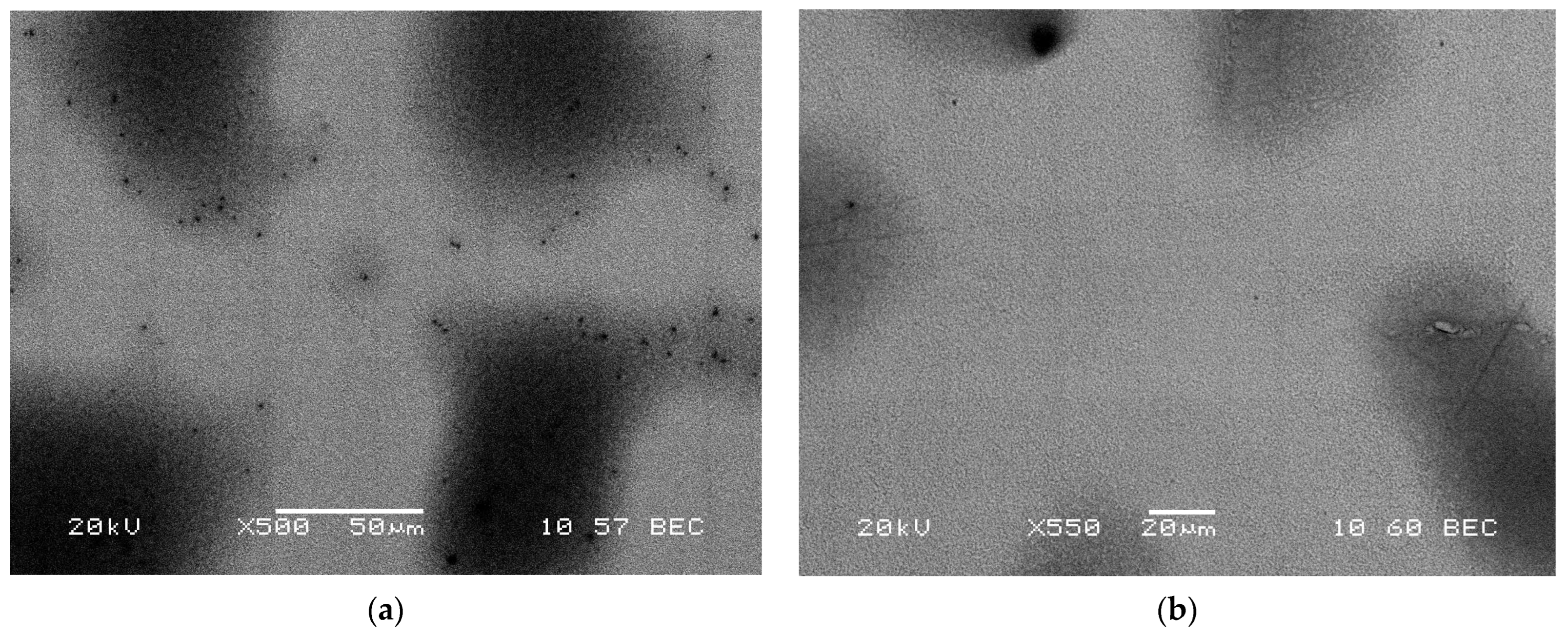
A segregated structure typical of this alloy can be seen in
Figure 1a, where the lighter dendrite cores are significantly enriched in tungsten and rhenium while depleted in tantalum compared to the overall composition presented in
Table 1, producing the contrast seen.
By 1 h into the solution process, the dendritic structure is already homogenizing, yet by 8 h, as seen in
Figure 1c, TCPs are present toward the centre of the dendrites.
Figure 1d shows after 24 h of the solution process, and in this case, the micrographs suggest an entirely homogenous structure (consisting of evenly distributed ɣ’ surrounded with ɣ channels), with no sign of the dendritic structure left. No TCPs were seen throughout the sample after this solution time.
Using ImageJ to calculate a volume fraction of TCPs across the dendrite core region, an 8-h sample was recorded with a 1.15% Vf. This solution time was the only one where TCPs were found to be present. Additionally, the volume fraction is considerably lower than that found in the CMSX-10N samples and only comparable to the CMSX-10Ks’ lower recorded values.
3.2. CMSX-10K
CMSX-10K was chosen for its similar composition to CMSX-10N, the only alloy that has been identified with TCPs after solutions. CMSX-10N was developed from CMSX-10K, and a very similar behaviour was expected; apart from the rhenium content, there are only minor compositional differences between the alloys.
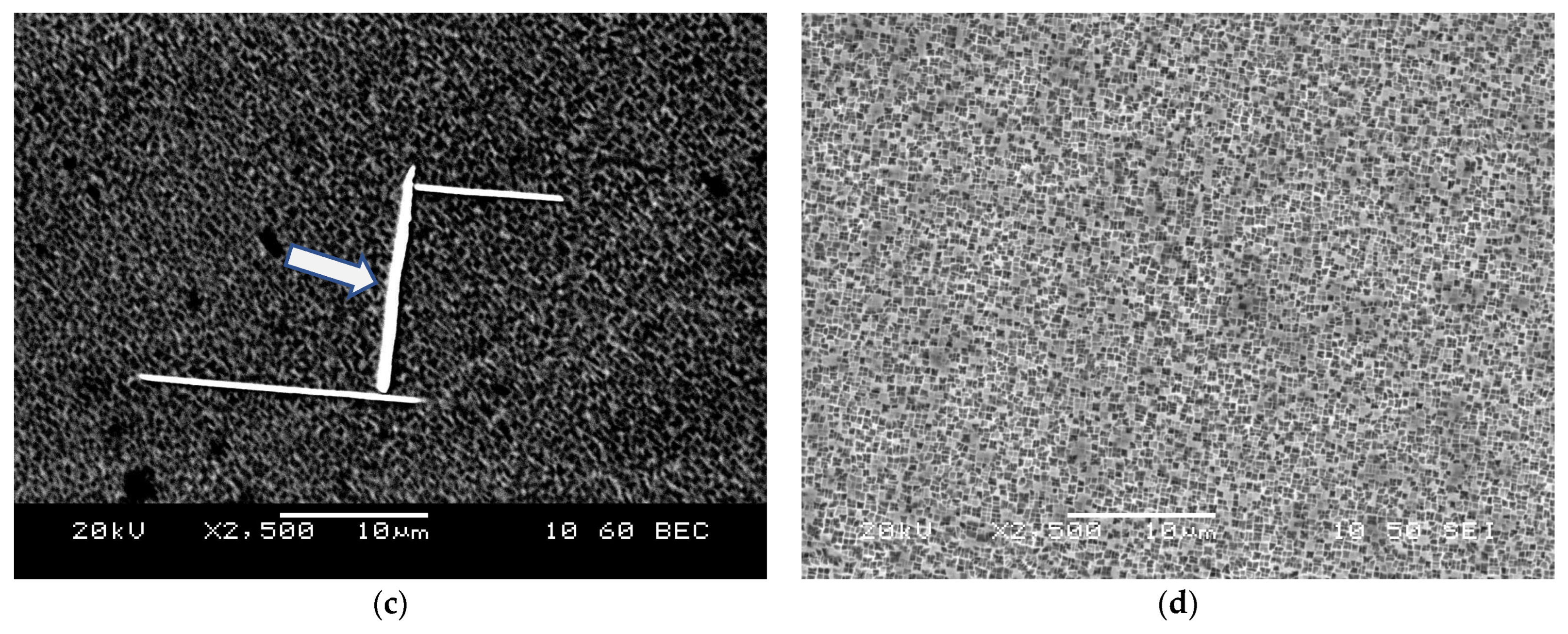
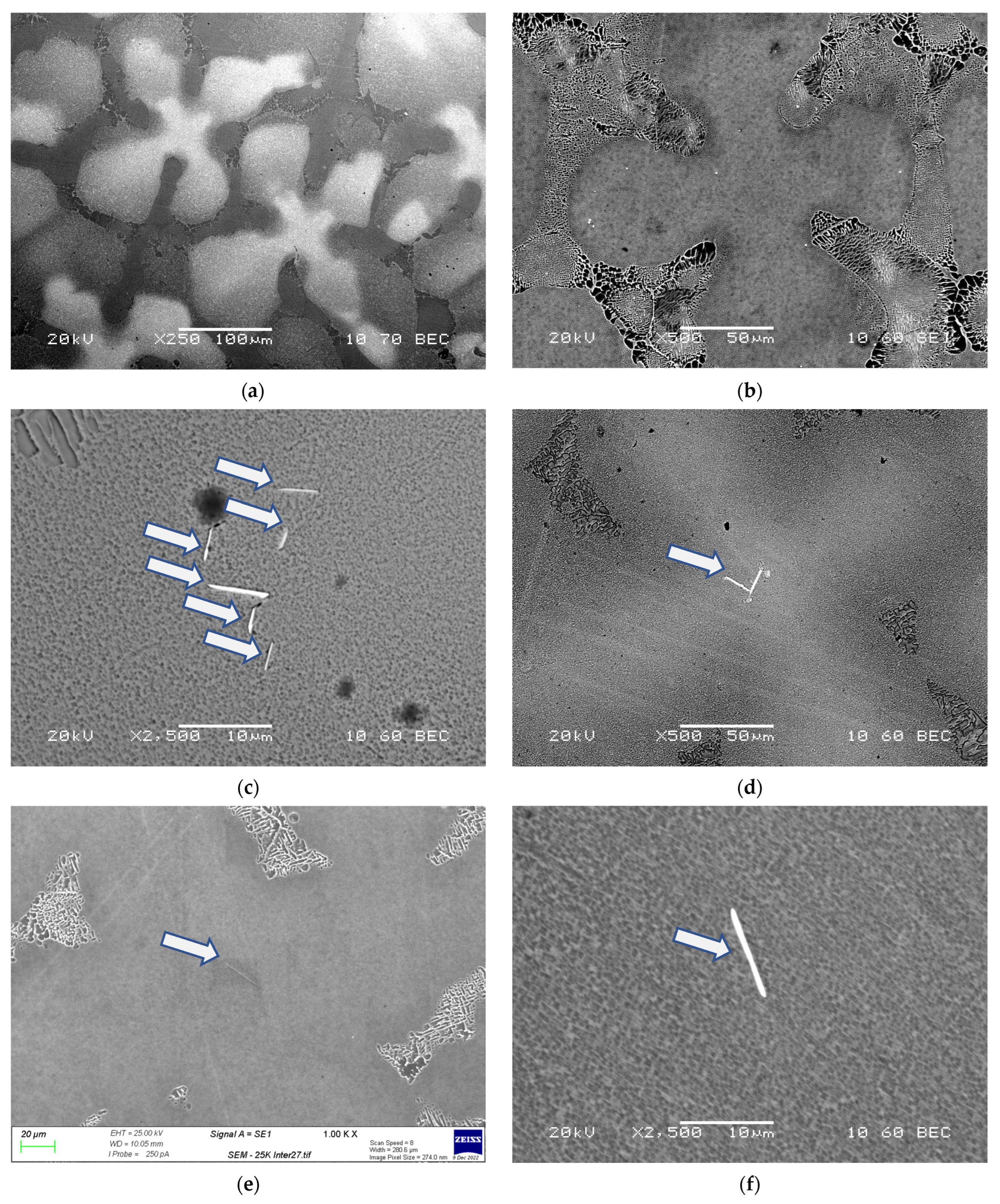
Figure 2 shows micrographs of CMSX-10K through the solution stages. Note that
Figure 2b is labelled 0-h; this refers to a sample that underwent the heating regime to the solution temperature of 1345 degrees Celsius before immediate quenching, without holding at the temperature, to study the effects of the heating regime on the microstructure. The lighter regions are the dendrites, where the heavier elements are concentrated. The contrast within the dendrite arms indicates the underlying presence of interdendritic material separating the secondary dendrite arms.
A typical segregated dendritic and interdendritic region can be seen in
Figure 2a, where the contrast is more significant compared to
Figure 1a, as the dendrite contains significantly higher concentrations of tungsten and rhenium. Note that some of the dendrite arms have a feinter contrast, with some arms possessing a composition similar to that of the dendrite cores, whilst others vary significantly. The gamma–gamma prime structure can be seen in
Figure 2b as typical of an as-cast single-crystal material.
Figure 2b shows TCPs already present, with varying morphologies, although typically long, needle-like structures (the images are only 2D, and therefore they could also be plate-like, as the literature would suggest [
10,
11]), they bridge across the surrounding ɣ-ɣ′ structure and typically reside in the dendrite core, but in image 2c a small precipitate can be seen in the dendrite arm on the right-hand side of the image.
Figure 2d,e also shows TCPs, which tend to form in small clusters within a single dendrite core. Individual TCPs are also common, but there are also many dendrites with no TCPs, showing large variations in TCP-forming potential between individual dendrites. No TCP phases were observed in the interdendritic regions.
Figure 2f shows a dendrite after 24 h of solutions; here the segregation is now minimal, and while some interdendritic regions can be seen on the edges of the image, a significant amount of homogenization has occurred, and the sample was absent of TCPs throughout.
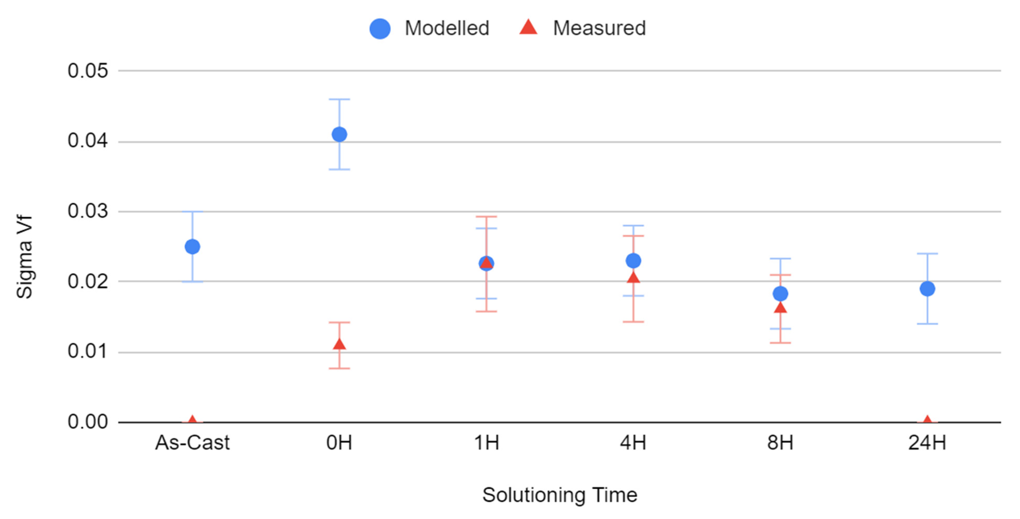
Figure 3 shows the volume fraction (Vf) of σ phase measured from the samples using ImageJ, compared to the value modelled from ThermoCalc using compositional measurements taken via EDX. The model assumed 30 min were available for precipitate formation, and although the quenching process would be much faster than this, the samples were kept in the furnace to prevent the sample from heating up again. Because of this, an overestimation in the model is expected.
In the as-cast state, the ThermoCalc models suggest there is a sufficient driving force (derived from the composition) for the precipitation of TCPs; however, the sample did not undergo the same 30-min quench but did cool from a molten state. However, no TCPs were seen in situ, and so the circumstances of the cooling during casting appear sufficiently different from cooling from the process of solution to not promote the precipitation of TCPs.
The modelling predictions were very similar to those measured, with the 1 h measured and modelled values varying by less than a percent. However, at 24 h, where none were seen, the modelling still predicted that some would precipitate. Some overestimation in the modelling data was expected, as it was known to overestimate the quenching time so that the results are so similar that one could argue the volume fraction of σ phase is higher than the composition alone could attest to.
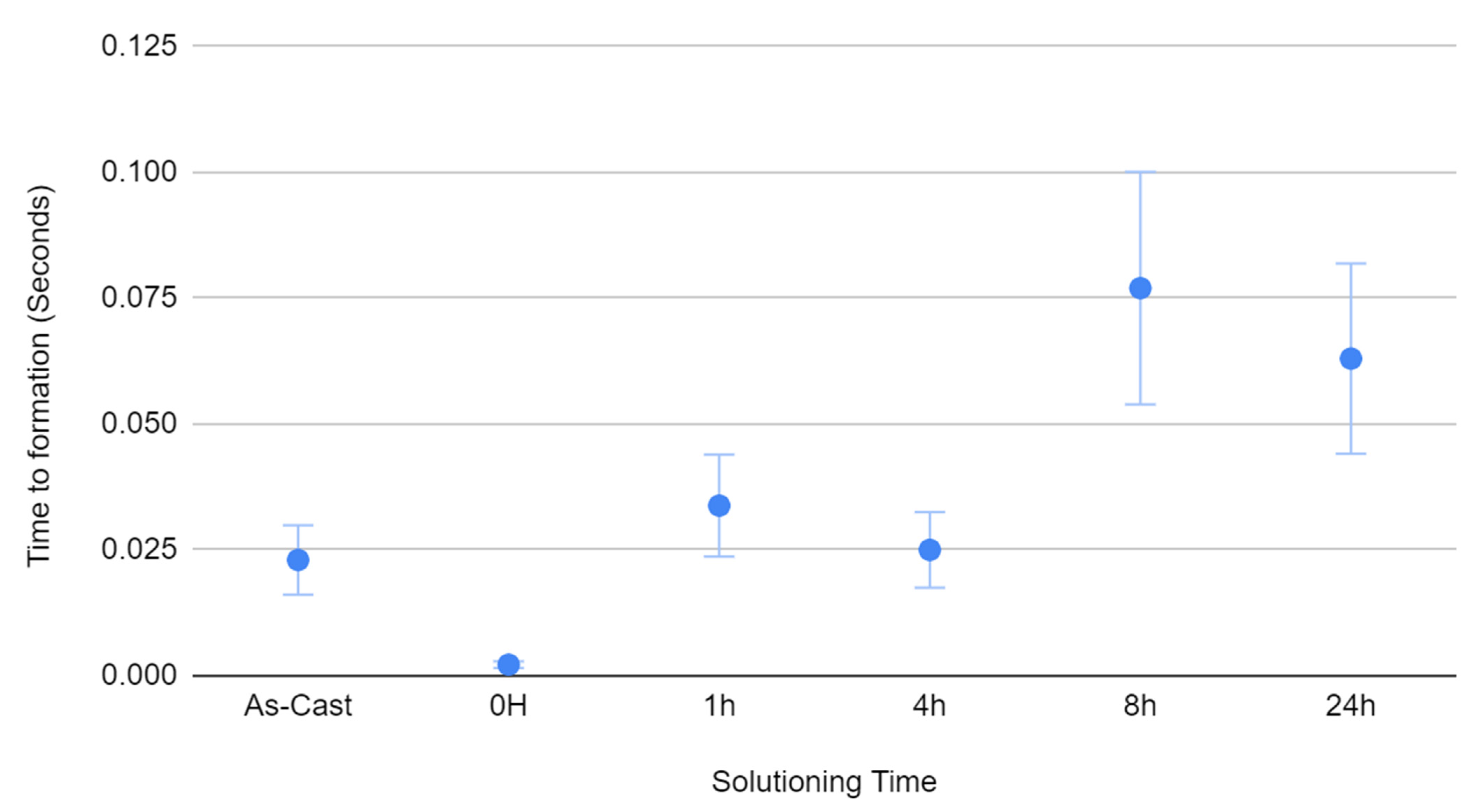
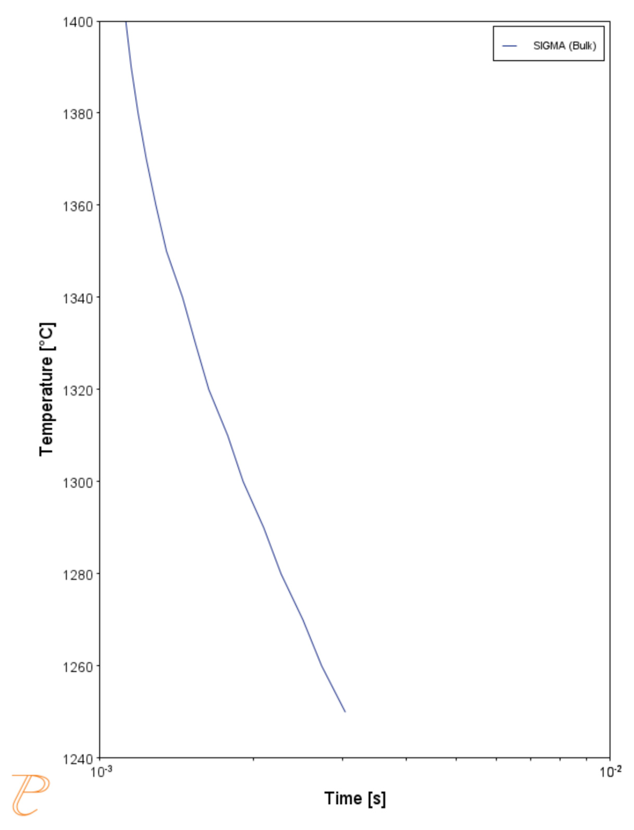
Modelled alongside this is the time to the formation of the σ precipitates, also through ThermoCalc in
Figure 4. The times refer to the length of time for a 0.1% volume fraction to occur. Immediately it can be seen that the times to formation are very fast, significantly faster than is typically seen from in-service blades [
3,
5,
10]. Their time to formation also increases with time, but still suggests a very rapid formation time at the end of the solution process, despite not being observed in practice.
3.3. CMSX-10N
CMSX-10N is the primary alloy studied for this work, as it has been reported to contain TCPs after the solution treatment [
11]. This previous work also demonstrates that the TCPs seen in these alloys are σ-phase. More tests were carried out on this alloy because of this and its ready availability, as it is a widely used alloy [
6,
12,
13].
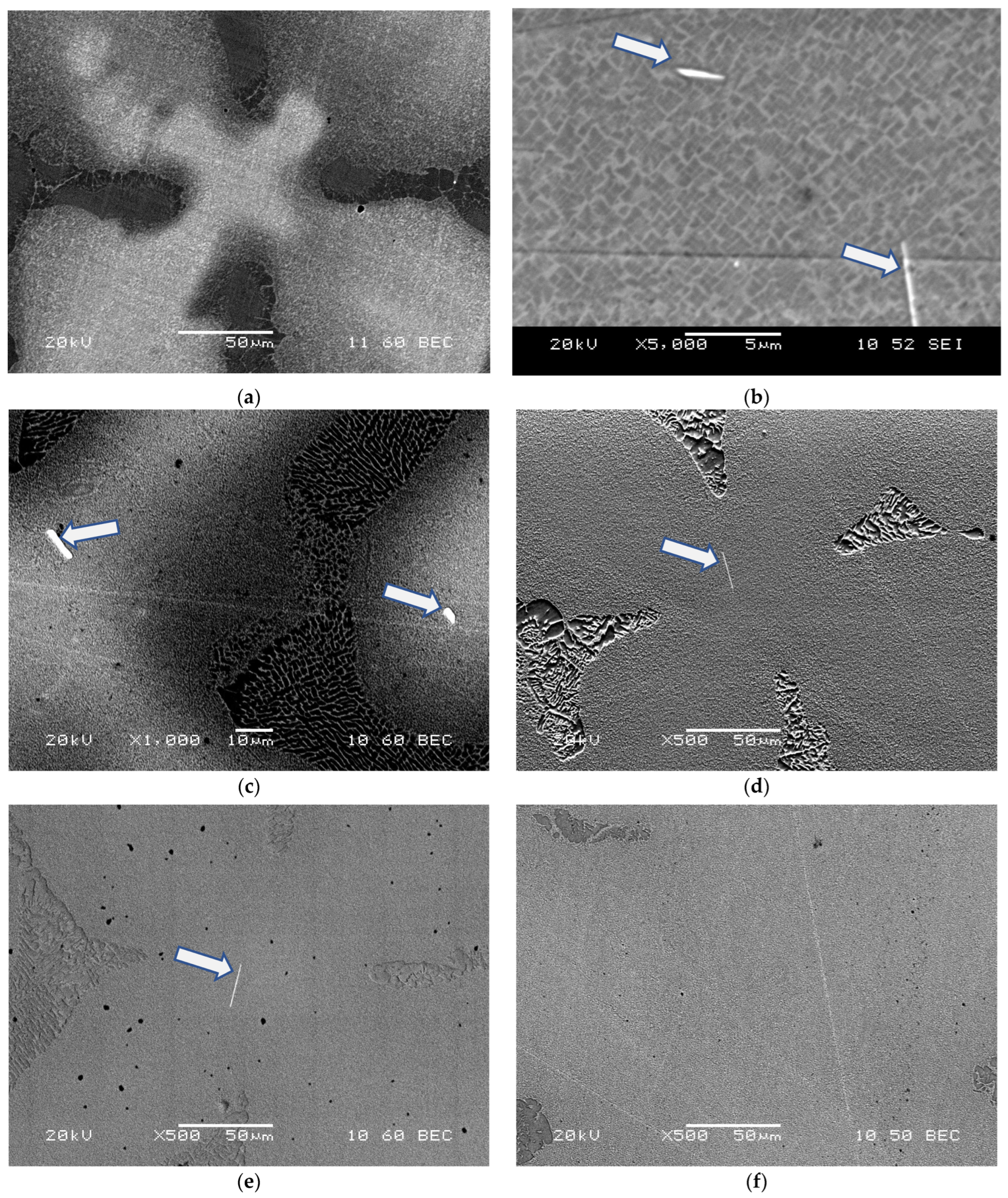
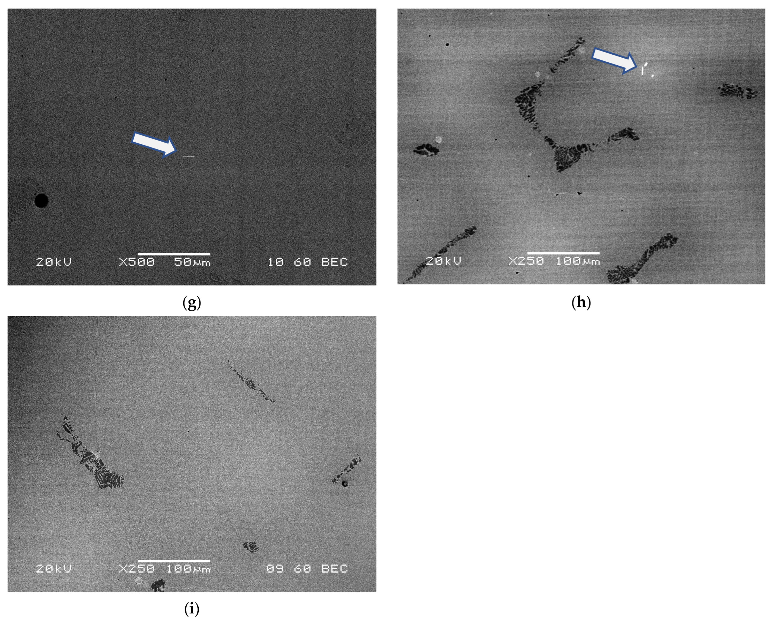
Figure 5 shows micrographs taken from each of the solution processes’ ages, with many containing TCPs; note that there are also 0 h samples as part of this alloy-specific study.
Figure 5a presents a very similar segregated microstructure as
Figure 2a; however,
Figure 5b lacks any TCPs, and none were found throughout this early stage of the solution process for CMSX-10N. However, the cells in
Figure 5c–h all contain TCPs to varying degrees.
Figure 5h, showing the microstructure after 24 h of the solution process, shows that TCPs remain, unlike CMSX-10K, and only after 48 h are there no TCPs present (
Figure 5i), despite the microstructure not being fully homogenized.
The TCPs present were seen to form either in clusters or as individuals, but almost always within the dendrite core, both as long needle-like precipitates and all smaller circular precipitates; however, these images only present a 2D insight into the material, meaning these needle-like precipitates could be plates and the circular precipitates needles if they were to extend into the depth of the material. This is seen in other works [
11]. Some TCP phases were observed in the dendrite arms, but none were seen in the interdendritic regions.
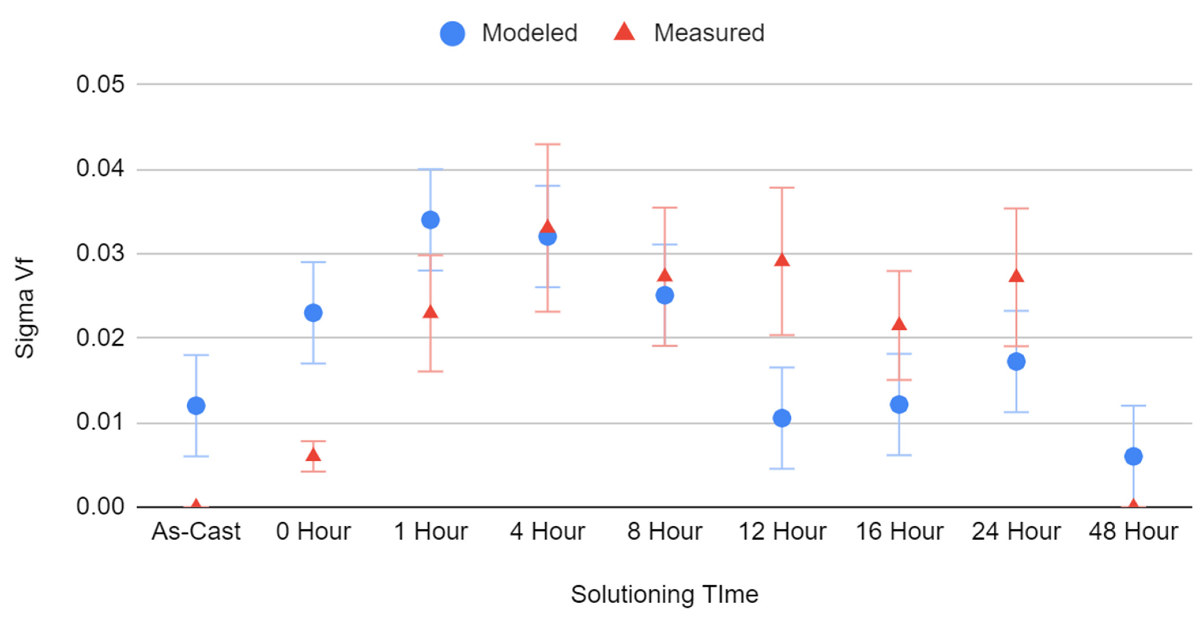
Figure 6 shows the volume fraction (Vf) of σ phase measured from the CMSX-10N samples using ImageJ, compared to the value modelled from ThermoCalc using compositional measurements taken via EDX. The modelled assumptions were the same as those of
Figure 3.
The as-cast modelling predicts the occurrence of TCPs, although none were seen, and as with CMSX-10K, the model assumed the quenching behaviour it did not undergo.
An overestimate of TCPs is seen again during the early stages of the solution process, with a very close alignment during the middle section. In contrast to CMSX-10K, the model underpredicted the volume of TCPs at the later stages; however, at 48 h, none were reported in the modelling (a non-zero value is shown to account for errors) nor were any seen during microscopy.
Figure 7 shows a segment of a TTT curve for the surrounding temperatures of the solution profile, showing the rapid rate of formation for σ TCP is consistent at all surrounding temperatures.
4. Discussion
The immediate observation from the results is the appearance of TCPs at all; whilst there have been some reports of TCPs during the manufacturing process, they are limited. Long et al. [
4] reported their occurrence in the as-cast structure, which then decomposed during the solution process; they also reported σ phase being present, along with η, however, Long’s σ was nodular, whereas the η was platelet-like. Long did conclude that more σ precipitated from the platelet morphology of the decomposed sites of the nodular TCPs during the solution process.
However, no TCPs were seen in the as-cast state in these samples, and the same phenomenon cannot be used to explain their precipitation during the solution process. However, despite none being seen, there is a possibility they were not observed, and the modelling did suggest the possibility of TCPs, although the modelling regime used did not replicate the solidification process. However, in this study, no platelet η was seen, nor did it appear in the modelling, suggesting that these two occurrences of TCPs are rooted in different mechanisms.
Nader El-Bagoury et al. [
14] reported the occurrence of rhenium clusters in the as-cast state, as well as phases that possessed a needle-like morphology; however, neither of these phases was shown by TEM to be TCPs; the needle-like particles were delta phases, found alongside ɣ′′, and contained Nb, neither of which are observed in the alloys in question here. The rhenium clusters are only a handful of atoms large and are a common occurrence in rhenium-containing alloys [
15].
Fuchs suggested that TCPs could occur during the solution process under certain circumstances [
7], particularly if the solution process was shortened as it would lead to reduced homogenization. Fuchs reported that rhenium and tungsten diffusion was substantial only above 1340 degrees Celsius. This known behaviour identifies aluminium as the source of TCPs, at least in the 0 h treated sample. At these lower temperatures and shorter time frames, aluminium is the only element to undergo significant diffusion (Cr, Co, and Ni would diffuse at these temperatures too, but segregate relatively evenly on solidification).
As aluminium diffuses from the interdendritic region into the dendrite core, increasing the volume fraction of ɣ′, this concentrates the Re and W, which have yet to diffuse, in the ɣ channels. Kim showed the composition of the ɣ and ɣ′ is fixed [
13], severely limiting its ability to hold the excess rhenium and tungsten in solution. This oversaturation then precipitates out as TCPs, particularly in σ phase. Rae et al. reported that σ is typically the first to precipitate, but as a metastable phase that eventually returns to ɣ or a different type of TCP [
5]. However, the ThermoCalc models predicted σ would occur and would remain stable. The kinetics would lend itself to σ forming first, and the enriched concentrations would maintain the stability. This is reinforced by the dropping off of σ volume fraction with increasing solution time, as the Re and W have enough time to diffuse out of the cores into the interdendritic regions, with this reduction in σ volume fraction increasing with time.
The time to the formation of these TCPs is of particular note, as graphs 2 and 4 show precipitation times of less than a second, almost instantaneous, far from the prolonged periods generally assumed for TCPs [
16]. These longer-to-form TCPs are generally found at the surface, where there is an increased concentration of Al from the coatings [
6], whereas those in this paper are found within the bulk of the material, far from the surface, where the compositional non-equilibrium is the driver.
These data were modelled at the solution temperature, where the TCPs formed and were stable, unlike the metastable σ reported elsewhere [
5] and in the absence of ɣ′. These TCPs could form during the heat-up cycle, and as
Figure 5 shows, the time to the formation of TCPs is small at the surrounding temperatures too. Here the aluminium diffusion into the dendrite core causes an increase in ɣ′ before its dissolution into ɣ, allowing a concentration of TCP elements in the core and allowing quick precipitation of TCPs that are then stable throughout the solution process, continuing to grow until sufficient rhenium diffusion has occurred. Secondly, the TCPs could form at temperature, despite no ɣ′ being present, because the core would still be enriched in rhenium, with an increasing aluminium content in the early stages oversaturating the ɣ matrix, which, as shown by Kim [
13], has a fixed composition and must still reject the oversaturation of rhenium causing the precipitation of TCPs. A third option is that the TCPs form on quenching; as ɣ-′ forms during cooling, the ɣ is supersaturated with rhenium as it is rejected from the ɣ-′; from here, the quick formation times of TCPs at these compositions allow for the formation of TCPs on cooling. Whilst this last theory does not reflect the modelling which suggests their stability at the solution temperature, it is hard to distinguish the methods without in situ imaging.
The first of these, where TCPs form on heating, seems the most promising, as the still present ɣ′ would still concentrate rhenium into the ɣ matrix, increasing the driving force for TCP precipitation. However, precipitation and growth could still occur at this temperature, albeit to a reduced degree without the ɣ-′ concentrating effects, and furthermore, precipitation could occur on cooling too. If multiples of these effects are occurring, it would explain the discrepancy between the modelling data and experimental data, as the modelling only assumed at-temperature precipitation.
5. Further Work
There is significant precipitation of TCPs during the solution process of rhenium-containing alloys; however, the mechanism by which it occurs is still not fully understood. It is clear that in the early stages of the solution process, the heating cycle has the most significant effect; however, TCP volume fractions continue to increase in the early stages of the solution process. A more thorough investigation of these early times would be necessary to improve our understanding of these mechanisms.
Studying more alloys would also be of use, as rhenium is not the only former of TCPs; furthermore, alloys with different ɣ′ fractions would be of interest if this is in fact the prime driver for TCP precipitation via rhenium rejection.
To pinpoint the exact time within the homogenization process that these TCPs form would also be of great use. To do so would require imaging the alloy during the solution process itself, which has numerous practical challenges, due to the extreme temperatures the microscopy equipment would have to be able to operate at.
Furthermore, the length of solution treatment appears vital in the removal of TCPs; there appears to be a cut-off point where TCPs are no longer present, but understanding, if this is a gradual change, or a steeper drop-off would help optimize solution treatments by adjusting the length of solution heat-treatment against minimal TCP precipitation prior to entry into service. These optimal solution times also vary from alloy to alloy, despite only small compositional changes, as each alloy would have a unique window to form TCPs during the solution process. This last step is of high importance, as significant work is currently going into shortening the solution procedure because of its associated high costs during the manufacturing process for turbine blades. However, with certain alloys, these works are likely to run into issues with TCP precipitation.
6. Conclusions
TCPs precipitate during solution heat treatment of rhenium-containing alloys, particularly those of high concentration (6%wt or more).
This occurs even at the earliest stages of the solution process, being present after the heating cycle to the solution window;
This is most likely driven by aluminium diffusion into the dendrite cores from the interdendritic region before the other elements can homogenize, enriching the ɣ matrix and causing the rejection of the rhenium, potentially from the formation of ɣ′, which would further concentrate the rhenium in the ɣ matrix;
Holding at the solution temperature for sufficient times allows sufficient rhenium diffusion so that TCPs do not form. However, in the case of CMSX-10N, this time frame exceeds the 24 h usually used for its homogenization in a production environment;
Further work is needed to understand the mechanism behind the initial precipitation of TCPs and how it varies across different alloys.


