
Defective Graphene Effects on Primary Displacement Damage and He Diffusion at a Ni–Graphene Interface: Molecular Dynamics Simulations


1
Key Laboratory of Material Physics of Ministry of Education, School of Physics and Microelectronics, Zhengzhou University, Zhengzhou 450052, China
2
Department of Nuclear Science & Technology, Nanjing University of Aeronautics and Astronautics, Nanjing 210016, China
3
State Key Laboratory of Nonlinear Mechanics, Institute of Mechanics, Chinese Academy of Sciences, Beijing 100190, China
*
Author to whom correspondence should be addressed.
Crystals 2023, 13(2), 198; https://doi.org/10.3390/cryst13020198
Submission received: 25 December 2022
/
Revised: 17 January 2023
/
Accepted: 20 January 2023
/
Published: 22 January 2023
(This article belongs to the Section Inorganic Crystalline Materials)
Abstract
:Ni–graphene nanocomposites with high-density interfaces have enormous potential as irradiation-tolerant materials applied in Gen-IV reactors. Nevertheless, the mechanism wherein the intrinsic and/or irradiation-induced defects of graphene affect the irradiation tolerance of the composites remains poorly understood. Here, we investigate the effects of the two types of defective graphene on the displacement damage and He diffusion of the composites, respectively, using atomistic simulations. The introduction of the intrinsic defects of graphene has a significant effect on the Ni lattice structure near the Ni–graphene interface, especially showing that after displacement cascades, the number of defects gradually increases with the increase in graphene-defective size due to the formation and growth of stacking fault tetrahedra. The existence of the irradiation-induced defects of graphene does not diminish the ability of the interface to trap He atoms/clusters and even may be maintained or improved, mainly reflected in the fact that many isolated He atoms and small clusters can gradually migrate toward the interface and the fraction of He within the interface is up to 37.72% after 1 ns. This study provides an important insight into the understanding of the association relationships of defective graphene with the irradiation tolerance of composites.
1. Introduction
Designing an irradiation-tolerant material from the perspective of interface engineering has become one of the main consensuses among the nuclear materials community [1,2,3,4,5]. Graphene (Gr), attributed to its remarkable mechanical properties, high specific surface area, and light weight [6,7], exhibits enormous potential in building ultra-high-strength interfaces with metals [7,8,9,10,11,12]. Consequently, this concept is beneficial to bring in abundant metal–Gr interfaces and then may provide metallic matrices with excellent irradiation tolerance. In recent years, several research groups have successively reported the irradiation tolerance of composites and provided relatively abundant evidence for it [13,14,15,16,17,18,19,20,21]. For example, Kim et al. [13] found that vanadium–Gr nanocomposites have higher irradiation tolerance than that of pure vanadium after He-ion irradiation. Si et al. [14] showed that tungsten–Gr nanocomposites with a smaller period thickness have a stronger ability in suppressing the growth of He bubbles. Based on energetic He-ion implantation experiments, Liu et al. [16] demonstrated that aluminum–Gr nanocomposites exhibit substantially lower irradiation-induced strengthening magnitude, considerable total elongation, smaller lattice swelling, and a completely different deformation mechanism compared to the unreinforced matrix. Our previous simulation studies [19,20] revealed that nickel–Gr interfaces (NGIs) can serve as sinks and attract, absorb, and annihilate interstitials, vacancies, and He atoms/clusters.
Recent activities to develop Gen-IV nuclear reactors with better functionality and capability represent an even greater demand for the comprehensive properties of structural materials [22,23]. Benefiting from the excellent high-temperature mechanics (e.g., strength, toughness, and creep) and anti-corrosion properties, Ni-based alloys have become one of the candidate materials for various metallic components in Gen-IV nuclear reactors [24,25,26], such as utilization as pressure vessels and heat exchangers in the molten salt reactor (service temperature range mainly at 625−1075 K) [27,28]. However, compared to their use in the current commercial reactors, Ni-based alloys must suffer higher neutron doses in the Gen-IV nuclear reactors [2,26]. Accordingly, massive point defects are produced and gradually gather into defect clusters (e.g., voids and dislocation loops) within the materials [29]. Furthermore, due to the large absorption cross-section of Ni with neutrons [24,30], a substantial number of He atoms are also generated by a two-step nuclear reaction and introduced into the alloys to form He bubbles at elevated temperatures [24]. Consequently, these defects are prone to induce the irradiation embrittlement, swelling, and phase instability of Ni-based alloys and then accelerate the performance degradation of the materials [24,31,32,33,34]. Given that the traditional Ni-based alloys rarely withstand the operating conditions of Gen-IV reactors, new design concepts for the materials are still necessary for resisting extreme irradiation. Thanks to the advantages of metal–Gr interfaces in reducing irradiation-induced defects and inhibiting the clustering of He atoms, Ni–Gr nanocomposites (NGNC) may provide a feasible path for solving the above problem [19,20,35].
However, a worrying issue has also followed. On one hand, many works in the literature have mentioned that a high level of topological defects and/or structural disorder in the form of vacancies, holes, dislocations, etc., can be generated on the surface of Gr during the preparation processes of Gr and its composites [36,37,38,39,40,41]. On the other hand, similar defects and/or disorder have also been found on the surface of Gr after energetic particle irradiation [42,43,44]. Considering the key role that Gr plays in stabilizing NGIs, the intrinsic and/or irradiation-induced defects of actual Gr may pose a significant challenge to the potential application of NGNC as an irradiation-tolerant material for Gen-IV reactors. Regrettably, because of the little attention it has received, to the best of our knowledge, only a few papers have reported on this issue for NGNC to date. Experimentally, lesser crystal defects and smaller He bubbles appear in NGNC than in its pure counterpart, although the surface morphology of Gr is continuously disrupted by the elevated temperature and irradiation [35]. On the simulation side, NGIs exhibit enhanced trapping ability to point defects, despite the gradually deteriorative irradiation damage of Gr [45]. These studies provide preliminary insights into the understanding of the association of the complicated Gr surface morphology with the irradiation tolerance of NGNC. Nevertheless, to develop NGNC with resistance to irradiation failure, more fundamental mechanisms about the issue need to be revealed urgently.
In this work, based on molecular dynamics (MD) simulations, two types of NGNC systems, which embedded Gr with intrinsic and irradiation-induced defects, respectively, were utilized to investigate the effects of defective Gr on the irradiation damage behaviors of the composites. The issue was dissected emphatically from two aspects. On one hand, the question of whether the sink character of NGIs with defective Gr still works needs to be answered, since intrinsic defects may be introduced into the Gr during preparation. To account for this, the evolution of point defects and atomic configurations near the NGI was discussed during displacement cascades depending on the size of Gr-intrinsic defects. On the other hand, because of the introduction of irradiation-induced defects of Gr after displacement cascades, the complicated Gr surface morphology will cause an effect on the He diffusion near an NGI. A previous study [20] found that the He concentration in the bulk can be considerably reduced, and the nucleation and growth rates of He clusters in the bulk were also delayed due to the NGI with a perfect Gr. Thus, a series of He dynamic behaviors, including their clustering, distribution, and interaction with NGIs, were also explored to clarify the change due to Gr’s structural integrity.
2. Simulation Methodology
All simulations were implemented based on the parallel MD code LAMMPS [46], and subsequent visualizations were rendered with OVITO [47]. The sandwich NGI models created in our previous works [19] were also applied hereafter, helping to compare them with each other. The Ni–Ni, C–C, and Ni–C interactions were described by the embedded atom method potential developed by Bonny et al. [48], the adaptive intermolecular reactive empirical bond order potential [49], and the 12–6 Lennard–Jones type of van der Waal’s potential [50], respectively. Moreover, to simulate the He diffusion in NGNC, the Lennard−Jones potential [51,52] and the Morse-3G interatomic potential [53] were adopted to describe the C−He and Ni−He interactions, respectively. The setting of each potential has been described elsewhere [19,20]. Each calculation was run by imposing periodic boundary conditions.
2.1. Displacement Cascade Simulations
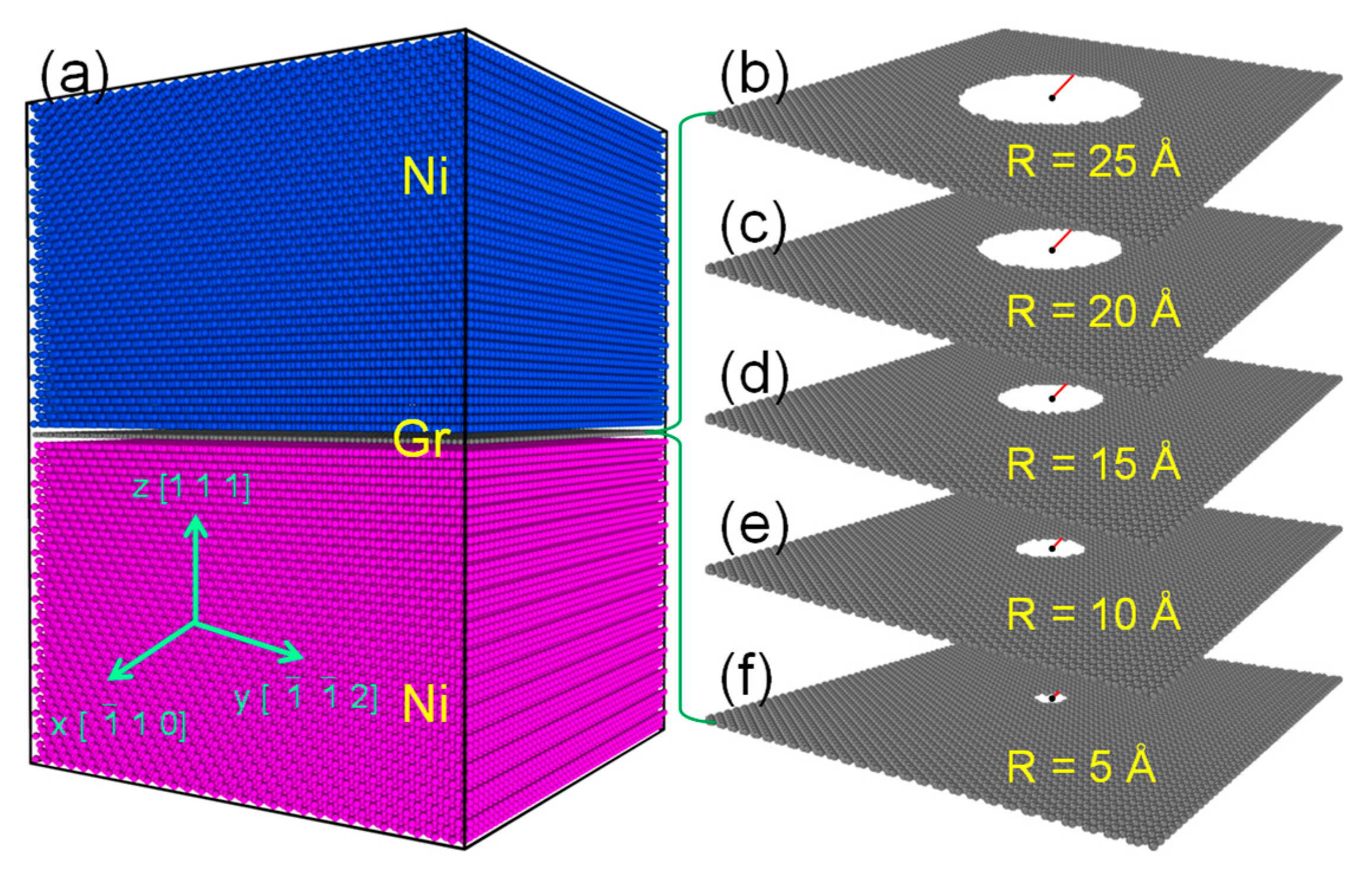
An original NGI model (see Figure 1a) with the dimensions of 124.6 × 129.5 × 174.5 Å3 (258,000 atoms), referring to that in Ref. [19], was generated first and then used to build another five systems containing defective Gr in different degrees (see Figure 1b−f). To facilitate the mimicking of the Gr-intrinsic defects, an ideal hole in the circle with a certain radius (R) was introduced into Gr by removing C atoms in the center of perfect Gr within the NGI. The R was determined to be 0, 5.0, 10.0, 15.0, 20.0, or 25.0 Å, and the corresponding defective model was named NG_R0, NG_R5, NG_R10, NG_R15, NG_R20, or NG_R25, respectively. Note that although this type of intrinsic defect is only one of many in Gr, its use is very beneficial for universally predicting the effect of Gr-intrinsic defects on the irradiation damage behaviors of NGNC. After a conjugate gradient (CG) minimization, each model was thermally relaxed with the Nose–Hoover thermostat (NVT ensemble) at 300 K for 10 ps until reaching a stable state. According to the identification method mentioned in the previous work [19], it can be found that in each system, the interfacial region consists of the Gr plane and two terminal Ni-atomic planes near the Gr, and the rest belongs to the bulk region.
Subsequently, displacement cascades were activated in each system by launching a primary knock-on atom (PKA) with 5 keV, and the PKA was introduced at 15.0 Å away from its interface and was incident perpendicular to the interface. During cascades, the outer layer with a thickness of 5.0 Å was forced to dissipate the heat using a Nose–Hoover thermostat (NVT ensemble), while atoms within the inner region were allowed to move adiabatically using the NVE ensemble. The thermostat temperature was regulated at 300 K. Each simulation was completed in 63 ps. The Wigner–Seitz cell method [54] was employed to detect the point defects surviving in the bulk region. As a control, the displacement cascade simulations of pure Ni with the corresponding intrinsic defects (named N_R0, N_R5, N_R10, N_R15, N_R20, and N_R25) were also performed. All the settings of the simulation methods for pure Ni were accordant with those of NGNC.
2.2. He Diffusion Simulations
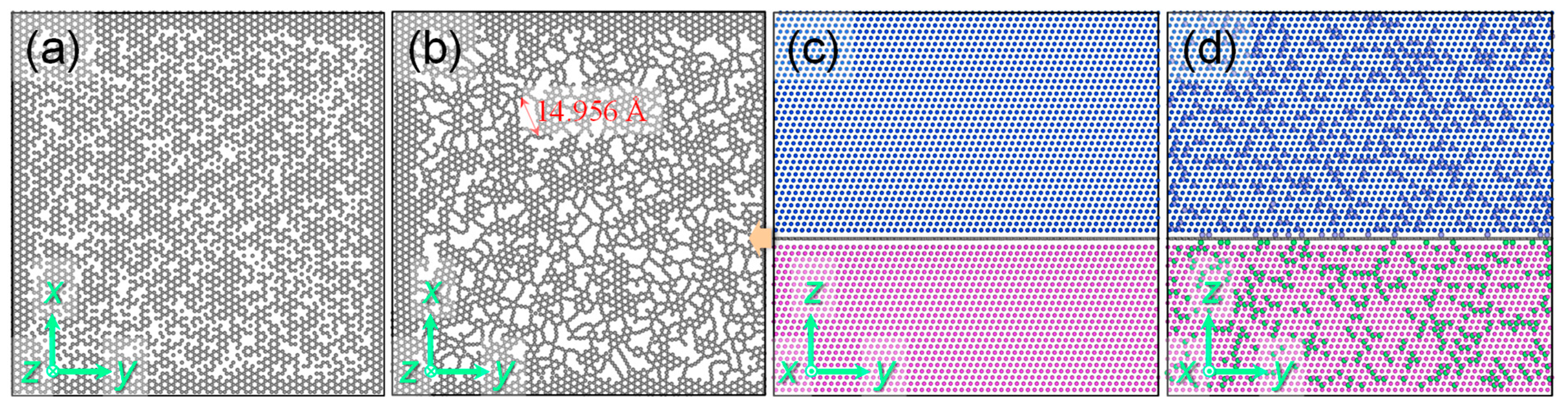
Likewise, another original NGI model with the dimensions of 125.2 × 129.6 × 125.6 Å3 (186,992 atoms), referring to that in Ref. [20], was used to build the derivative system containing Gr with irradiation-induced defects. The defects of Gr were generated first by deleting 1206 C atoms randomly (approximately 20 at.% of total C atoms in the Gr, shown in Figure 2a), and then the damaged NGI system was subjected to a CG minimization to release the stress. It can be observed that the interfacial Gr is severely disordered due to relaxation (see Figure 2b), in which the size of the largest hole can be up to approximately 15.0 Å, but the interface configuration is still well maintained, without miscibility of Ni atoms around the Gr (see Figure 2c). On this basis, a He concentration of 4970 appm (or 0.5 at.%) was introduced into the system by adding He atoms at different random sites (see Figure 2d). Subsequently, the model containing He atoms was relaxed at 0 K for 10 ps, and then heated up to 823 K, remaining constant thereafter. During thermal relaxation, the system was equilibrated with a Nose–Hoover thermostat–barostat (NPT) ensemble for 1.0 ns to ensure no significant fluctuation in pressure. He clusters were identified once the separation distances between different He atoms were less than a cutoff radius of 3.0 Å.
3. Results and Discussion
3.1. Defective Graphene’s Effect on Displacement Damage
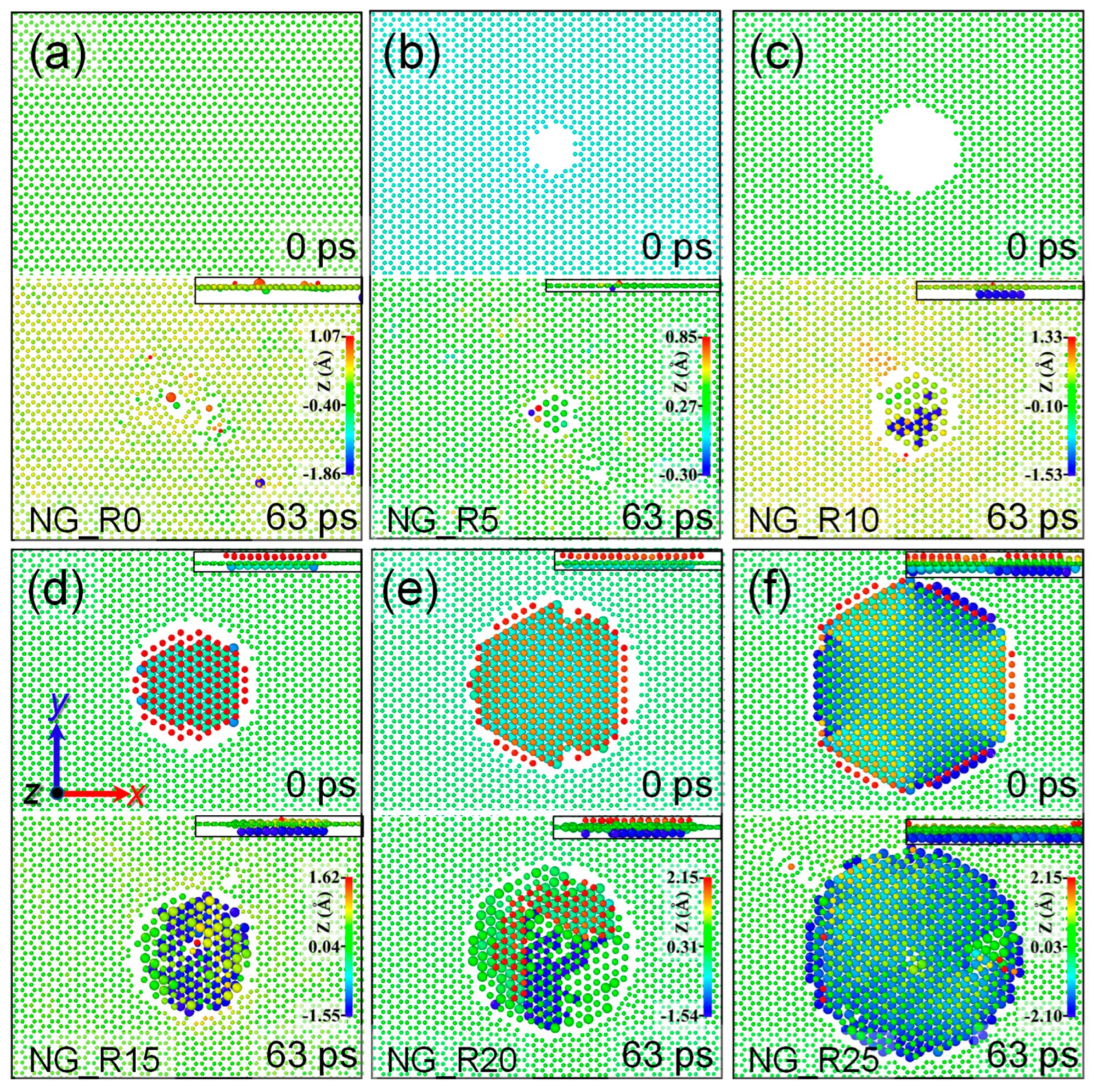
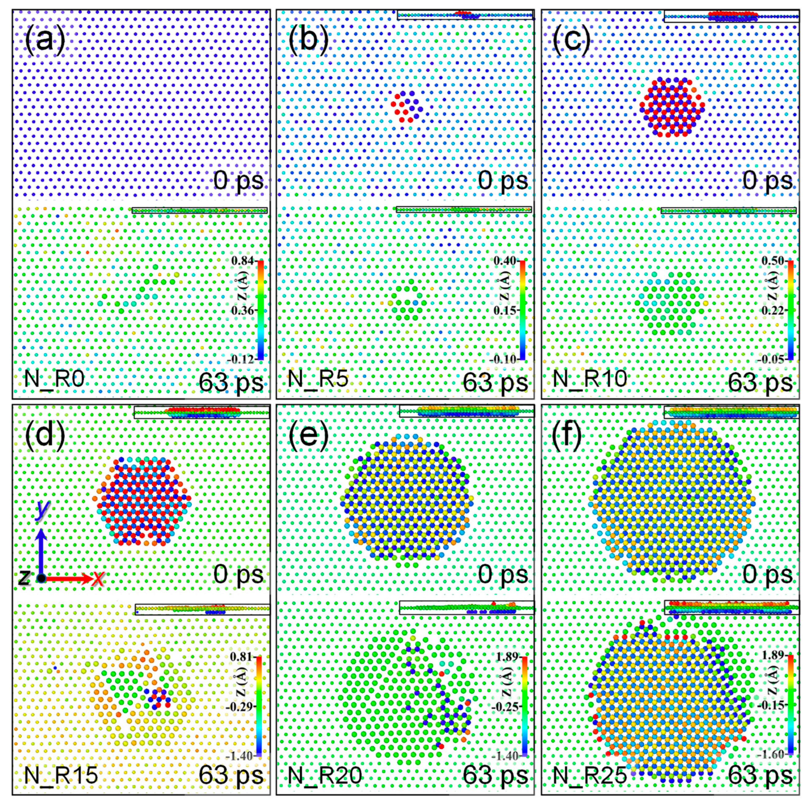
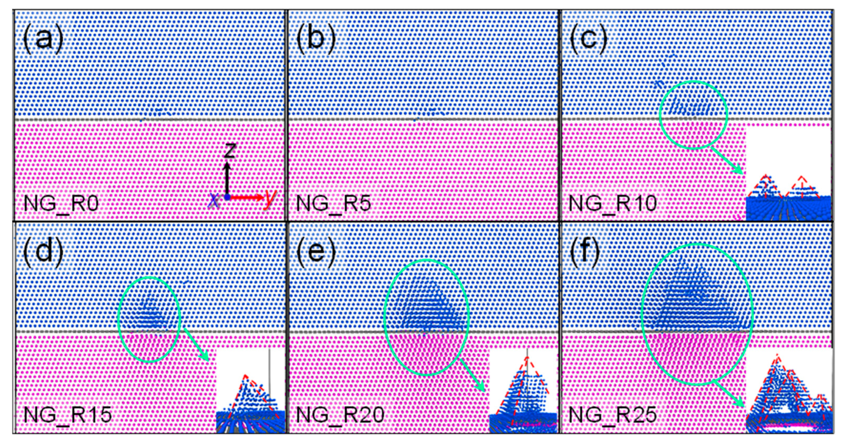
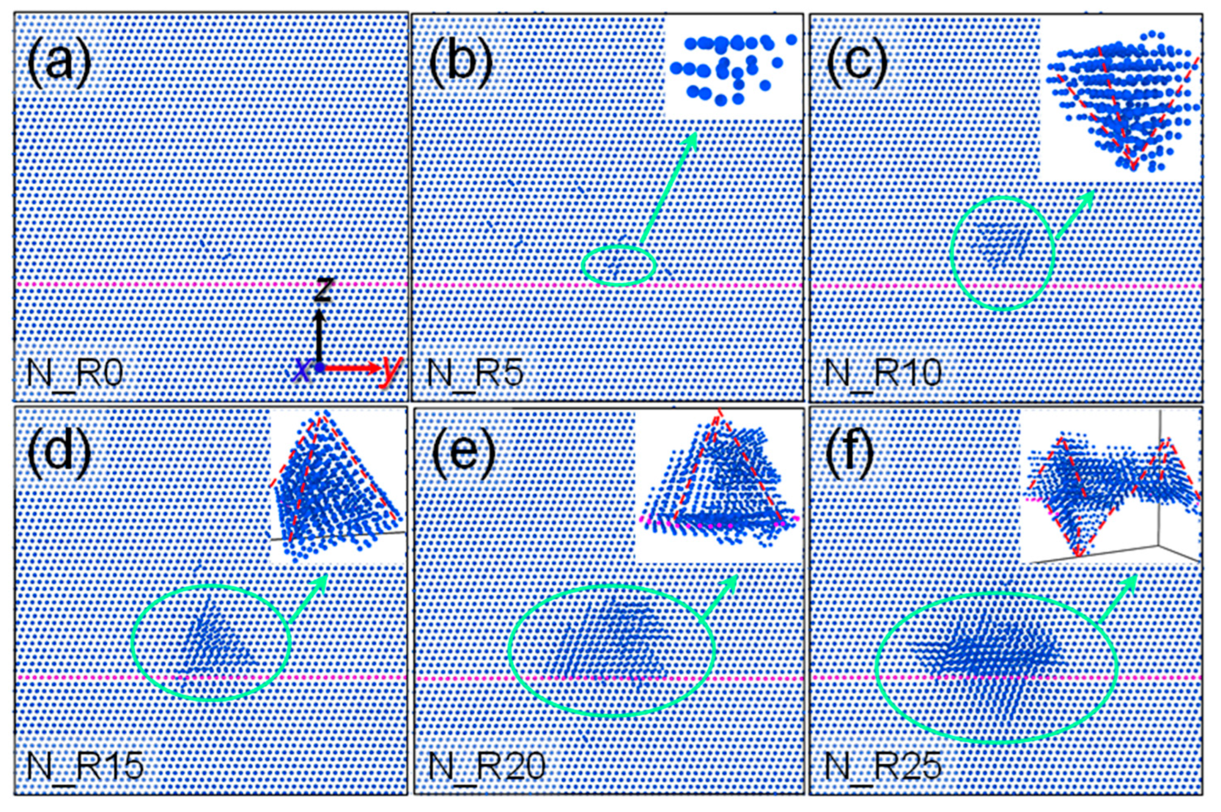
The C atoms around the Gr-defective region of each NGI model at the beginning and ending moments of cascades are exhibited in Figure 3, and the corresponding Ni atoms in the channels between Ni and Gr are also shown to highlight their miscibility. At 0 ps, there are no Ni atoms appearing in the Gr-defective region when R ≤ 10 Å, while the opposite scenario emerges when R > 10 Å, since the intrinsic hole in Gr has been unable to weaken the mutual attraction between the Ni atoms above and below it and triggered more and more Ni atoms to enter the Gr-defective region. Note that the NG_R10 was thermally relaxed for an additional 100 ps before cascades but remained structurally stable. As a result, the miscibility between Ni atoms occurred before cascades when R > 10 Å. At 63 ps, Ni atoms are present in the Gr-defective region of each NGI model, which becomes more pronounced with the increase in R. Due to cascades, the Gr-defective size has a slight increase when R ≤ 10 Å, while it is almost unchanged when R > 10 Å. Most of the similar phenomena also occur in pure Ni, as shown in Figure 4. However, at 0 ps, the miscibility between Ni atoms near the intrinsic defect layer in pure Ni still occurs, even if R ≤ 10 Å, in turn indicating that Gr has a stronger ability to inhibit the miscibility of Ni atoms.
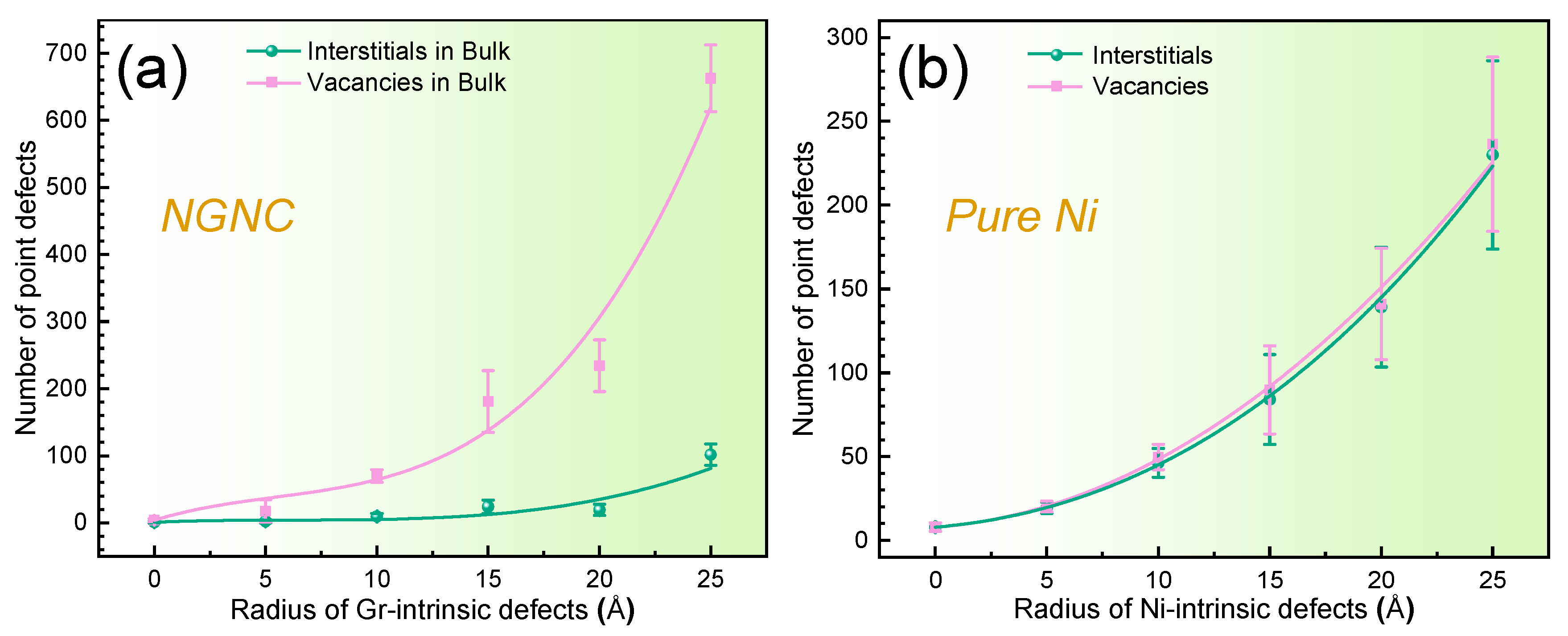
The number of point defects surviving in the bulk of NGNC or pure Ni as a function of the size of intrinsic defects is shown in Figure 5. In both NGNC and pure Ni, the number of point defects gradually increases with the increasing R. However, independent of R, the number of interstitials surviving in the bulk is always less than that of vacancies, while the two are essentially equivalent in pure Ni, implying that apart from the faint effect of local stress around the intrinsic defects on Ni interstitials or lattice atoms due to cascades, the characteristic that NGIs preferentially capture interstitials still works well and energetically induces Ni interstitials or lattice atoms to cover the Gr-intrinsic defect region. As mentioned in Ref. [45], although the irradiation-induced damage degree of Gr within the NGI gradually aggravates, the self-healing of irradiation defects in the bulk can be further enhanced by the NGI instead. In Figure 5a, the difference in the number of interstitials and vacancies exhibits a gradual increase with the increasing R, indicating that the partial absorption ability of NGIs improves. These suggest that regardless of the Gr-intrinsic defects or the Gr-irradiated defects, they contribute, to some extent, to the enhancement of the sink capability of NGIs. Compared with pure Ni, the total number of defects in the bulk of NGNC is smaller when R ≤ 10 Å, especially the part of the interstitials, indicating that, under this circumstance, the defective NGI still can promote the recombination and/or annihilation of irradiation-induced defects. When R > 10 Å, in both NGNC and pure Ni, the rate of point defect growth becomes fast. Among them, the growth rate of vacancies in NGNC is the fastest, while it is the slowest for interstitials in NGNC. These results may originate from the fact that most of the sink characteristics of NGIs are weakened as the Gr-defective size exceeds a certain value, but the role of the partial absorption of NGIs still can be played. Therefore, in order not to reduce the capacity of NGIs in suppressing irradiated defects of the bulk region, regulating the Gr-defective size is very necessary during experimental preparation.
Gr-intrinsic defects have great impacts on the formation and evolution of Ni defects, which may eventually be reflected in the change in the Ni crystalline structure near the NGIs. To illustrate this, snapshots of the six NGNC models extracted from the ending moment of cascades are shown in Figure 6. For NG_R0 and NG_R5, the irradiation-induced defects in the bulk only form several very small clusters near the NGI. However, when R reaches 10 Å, two neighboring stacking fault tetrahedra (SFTs) with small sizes have been hatched. With the increase in R, the embryonic SFTs gradually grow. In particular, apart from the formation of two small embryonic SFTs, another SFT-like structure with a large size in NG_R25 becomes closer to taking shape. In fact, we have also observed that an SFT-like structure emerges before cascades when R ≥ 10 Å, but its size is much smaller than that after cascades. This suggests that the occurrence of dramatic crystalline disorder in the Ni matrix is subject to the synergistic effects of Gr-intrinsic defects and irradiation. Combined with Figure 5a, it can be further inferred that the formation and growth of SFTs near the NGI are directly responsible for the rapid increase in point defects. Singh et al. [55] have reported that the freshly produced SFTs may grow by absorbing vacancies and may shrink by absorbing interstitials. Given the significant growth in both the number of vacancies and the size of SFT-like structures when R > 10 Å, it is easy to believe that an embryonic SFT intensifies the influence of collision cascades in generating irradiation-induced point defects. Since the vacancies are difficult to migrate and close to the embryonic SFTs in their first stage, most of the vacancies are biased towards capture by the SFT-like structures and then cause the growth of SFTs, which in turn results in a large number of vacancies remaining in the bulk of NGNC. Different from vacancies, interstitials migrate easily and are biased by the NGI, resulting in the capture of most interstitials by the interface. In other words, only a few interstitials remain in the bulk. The larger the scale of SFT-like structures before cascades, the more significant these phenomena become after cascades. This explanation fits well with Figure 5a. As a control, the corresponding snapshots of pure Ni are also displayed in Figure 7. Similarly, the larger size of intrinsic defects in pure Ni also induces more complicated SFT-like structures. Therefore, the main source of SFTs, i.e., Gr-intrinsic defects, besides the irradiation, should be eliminated as much as possible for the irradiation tolerance of NGNC.
3.2. Defective Graphene’s Effect on He Diffusion
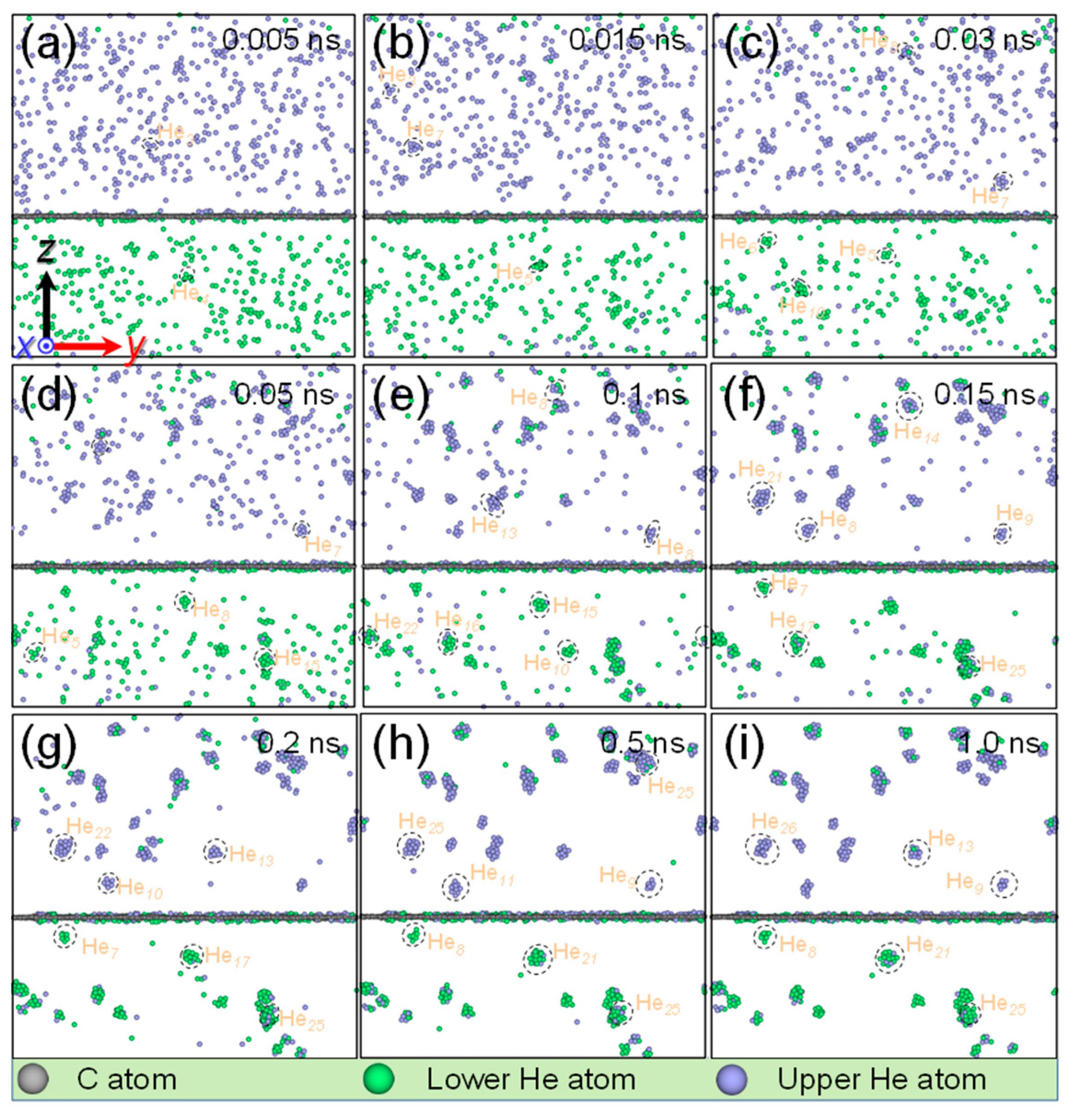
The He diffusion behavior near the NGI with defective Gr at 823 K is shown in Figure 8. At the beginning, 928 He atoms are separated from each other and distributed at different random tetrahedral interstitial sites in the system. At 0.005 ns, several small Hen clusters (n up to 4) start to form in the bulk. At 0.015 ns, the sizes of the He clusters further increase, and the largest cluster consists of seven He atoms. At 0.03 ns, because of the trapping of NGI, isolated He atoms rarely survive near the interface. We can observe one significant He diffusion phenomenon from the He atoms entering their opposite bulk, which becomes more pronounced with time. At 0.05 ns, several He clusters close to the interface can exist stably and even grow further, instead of being trapped by the NGI, implying that the clusters have been pinned and become stable nucleation sites. For example, a He7 cluster is generated at 0.03 ns and remains in its configuration at 0.05 ns, and a He5 grows to be a He8. At 0.1 ns, the number of He clusters is almost comparable to that of isolated He atoms, and the size of the largest cluster reaches 22. At 0.15 ns, the already existing clusters have become largely stable—namely, no longer aggregating with each other or dissociating—and they can compete with the interface in trapping He atoms. At 0.2 ns, the largest cluster with 25 He atoms has not changed in size since it appeared at 0.015 ns, and hereafter it remains the largest, implying that the growth of clusters in the bulk has almost reached saturation. After 0.5 ns, most of the isolated He atoms in the bulk have been absorbed by other He clusters or trapped by the interface. The He cluster size and distribution roughly remain unchanged until 1.0 ns. Throughout the simulation process, isolated He atoms and small clusters gradually aggregate into large clusters or migrate toward the interface, while the stable clusters may be pinned by the vacancies in the bulk and are difficult to migrate or be captured by the NGI. Compared to the NGI containing perfect Gr at 800 K [20], the ability of the defective NGI to trap He atoms/clusters does not seem to have diminished and even may be maintained or improved, which is mainly reflected in the following. First, the clusters in the bulk of the defective NGI model are roughly comparable in size and number to those of the perfect NGI model after 1.0 ns. Second, a higher temperature in the defective NGI model (at 823 K) compared to the perfect NGI model (at 800 K) does not intensify He clustering (especially the largest cluster) in the bulk.
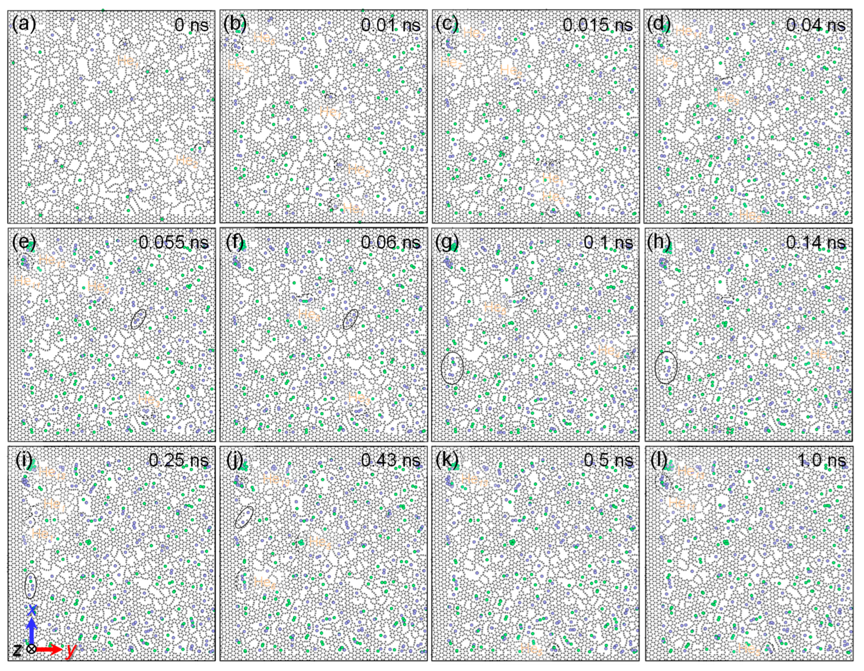
Further, the He diffusion behavior within the NGI is also observed and shown in Figure 9. Initially, He atoms are distributed randomly at both the Gr-perfect and Gr-defective sites, and most of them are separated from each other. At 0.01 ns, the He atoms, gradually captured by the NGI, increase the interfacial He concentration and then improve their clustering probability within the NGI, such as the formation of He3 and He5 clusters. The He clusters show higher stability at the Gr-defective sites than at the Gr-perfect sites. For example, a He2 cluster at a Gr-perfect site at 0.01 ns dissociates into two isolated He atoms, and they are absorbed in two different defective sites at 0.015 ns. Moreover, an isolated He atom at a Gr-perfect site is attracted to its neighboring He2 cluster at a Gr-defective site at 0.01 ns, resulting in the formation of a He3 cluster at a Gr-defective site at 0.015 ns. At 0.04 ns, the He3 and He5 clusters at 0.01 ns grow further into He9 and He11 clusters, respectively, by absorbing the He atoms from the bulk. Several He atoms or clusters at different defective sites adjacent to each other could aggregate into a single cluster through the open channels between their defective sites, such as the aggregation of an isolated He atom and a He2 cluster at 0.015 ns into a He3 cluster at 0.04 ns. Without the help of the channels, He atoms or clusters are difficult to aggregate into the same cluster, even if they are very close to each other. For example, the three different isolated He atoms in a solid oval remain in their configurations from 0.055 to 0.06 ns. However, not all He clusters at the Gr-defective sites tend to grow, and some may self-dissociate. One typical example is that the He4 at 0.1 ns gradually dissociates into an isolated He atom and other defects at 0.14 ns. Another possible mechanism is that the aggregation of He from different defective sites through the channels needs at least one pre-existing cluster. For example, the two isolated He atoms are difficult to cluster from 0.25 ns until 1.0 ns, despite the existence of a channel between them. After 0.043 ns, the He cluster size and distribution also roughly remain unchanged until 1.0 ns, consistent with that in the bulk. Thereafter, the change in He clusters is mainly presented in the relaxation of their configurations, such as the rotation of the He5 cluster from 0.5 to 1.0 ns. Compared to the bulk, the clusters within the defective interface have a high number density but small sizes. Different from the NGI containing perfect Gr, the He atoms or small clusters within the defective interface do not form very large clusters, and even many isolated He atoms survive. This may be because the Gr-defective sites have lower formation energies and higher diffusion barriers for the He atoms/clusters than those in the perfect interface [45], resulting in the inhibition of He diffusion along the defective interface.
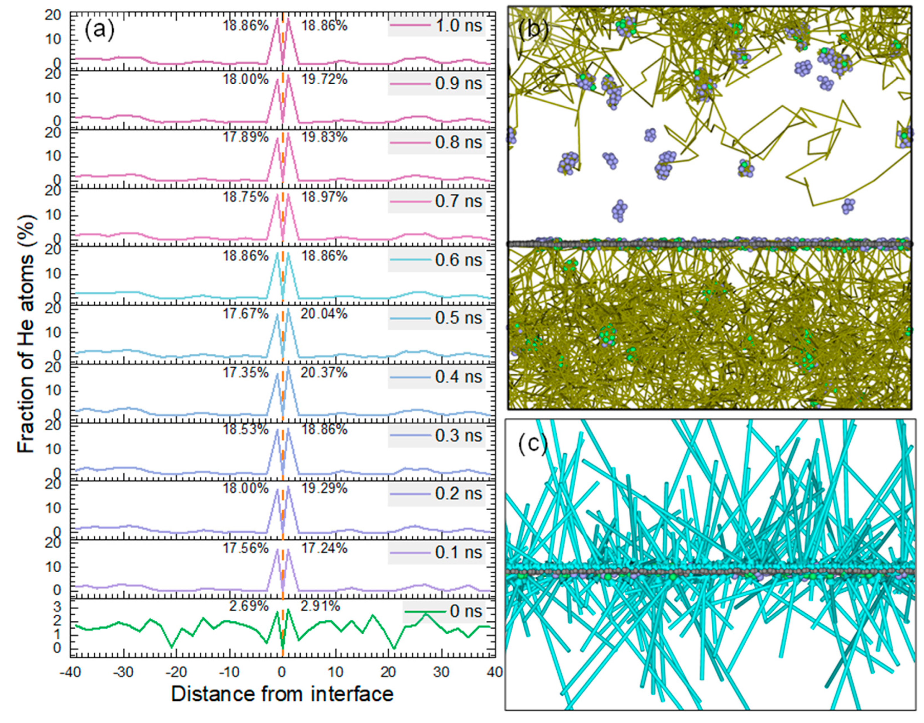
To quantitatively understand the effect of defective NGIs on He diffusion, we subdivide the model into several plates with 2 Å thickness along the z-axis, with the Gr as the center, and calculate the local He fraction based on the ratio of the number of He atoms in each plate to their total number in the system. Figure 10a shows the He fraction profiles at different times. At 0 ns, the distribution of He atoms in the system is roughly uniform despite the fluctuations, and the fractions of He atoms on both sides of the interface are relatively high but not yet significant. At 0.1 ns, the strong precipitation of He atoms occurs at the NGI, manifesting in the He fraction increasing from 2.69% (or 2.91%) to 17.56% (or 17.24%). At 0.2 ns, the fractions of He atoms on both sides of NGI exhibit a further increase, but the increasing rate becomes slow, with only an increase of 2.05% (or 0.04%) in 0.1 ns. At 0.3 ns, the total fraction of He within the interface improves by 0.01% more than that at 0.2 ns. At 0.4 ns, an increase of 0.33% in the total fraction of He within the interface occurs compared to that at 0.3 ns. Thereafter, the total fraction of He within the interface almost remains constant at around 37.72%. This suggests that the defective NGI has a strong ability to capture He atoms from the bulk, especially before 0.1 ns, leading to a rapid increase in the interfacial He concentration; meanwhile, the interface is unable to capture He atoms from the bulk after 0.1 ns because He atoms in the bulk gradually aggregate into clusters. After 0.4 ns, the fractions of He on both sides of the interface are converted into each other, with no change in the total fraction, which may be because some of the He atoms can penetrate through the defective sites of Gr into the other side of NGI, but they are unable to break away from the interface and jump further into the other side of the bulk. This can be demonstrated visually by the He-atomic diffusion trajectories (see Figure 10b), in which we can discover that no He atoms penetrate through the defective Gr into the other side of the bulk throughout the MD timescale. On the other hand, by showing the displacement vectors between He-atomic positions at 0 and 1.0 ns (see Figure 10c), it can be found that He atoms tend to diffuse toward the defective NGI, are then localized to the interface, and eventually are unable to exit the interface (observed along the direction of an arrow).
4. Conclusions
In the present study, we have carried out an investigation of the effects of defective Gr on the irradiation damage behaviors of NGNC from two aspects using MD simulations, including the displacement damage affected by the Gr with intrinsic defects and the He diffusion affected by the Gr with irradiation-induced defects. A summary of the most critical results drawn from this work is as follows.
(a) The introduction of the intrinsic defects of Gr has a significant effect on the Ni lattice structure near the NGI. Before cascades, the miscibility between Ni atoms above and below the defective Gr would emerge when R > 10 Å, even inducing the generation of embryonic SFTs in the Ni matrix, while it also can occur despite R ≤ 10 Å once cascades are activated. After cascades, the number of point defects gradually increases with the increasing R; especially when R > 10 Å, the rate of point defect growth becomes fast, which may be because of the formation of the SFT-like structures with large sizes in the Ni matrix.
(b) The existence of the irradiation-induced defects of Gr does not seem to diminish the ability of the NGI to trap He atoms/clusters and may even maintain or improve it. Significantly, besides the fact that some stable clusters may be pinned by the vacancies in the bulk, many isolated He atoms and small clusters can gradually migrate toward the interface. Different from the perfect NGI model, the He atoms or small clusters within the defective interface do not form large clusters, and even many isolated He atoms can survive. Compared to the bulk, the clusters within the defective interface have a remarkably high number density but small sizes, and the fraction of He within the interface is up to 37.72% after 1.0 ns.
Overall, regulating the Gr-defective size is very necessary during experimental preparation to avoid weakening the irradiation tolerance of NGNC. On the other hand, a moderate amount of irradiation-induced defects in the Gr may not weaken the irradiation tolerance of NGNC. All these results can provide a reference for the service life assessment of NGNCs in the Gen-IV reactors.
Author Contributions
H.H. performed the atomistic simulations, helped in data analyses, drafted and improved the paper, and designed and supervised the project. X.Y., X.G. and Q.P. assisted in modifying the manuscript and the discussion of the data. All authors have read and agreed to the published version of the manuscript.
Funding
This work was supported by the National Natural Science Foundation of China (No. 12105249), the Key Project for Science and Technology Development of Henan Province (No. 212102210195), the Henan Province Postdoctoral Science Foundation (No. 202102012), the Innovation Team Support Program for Cooperation of Young Talents & Enterprises in Zhengzhou University (No. 32320368), the State Key Laboratory of Nuclear Physics and Technology, Peking University (No. NPT2021KFJ05), and the Top Doctoral Talents Program of Zhengzhou University (No. 21350621).
Data Availability Statement
The data that support the findings of this study are available from the corresponding author upon reasonable request.
Acknowledgments
We are grateful for the computing resources provided by the National Supercomputing Center in Zhengzhou.
Conflicts of Interest
The authors declare no conflict of interest.
References
- Beyerlein, I.J.; Caro, A.; Demkowicz, M.J.; Mara, N.A.; Misra, A.; Uberuaga, B.P. Radiation damage tolerant nanomaterials. Mater. Today 2013, 16, 443–449. [Google Scholar] [CrossRef] [Green Version]
- Zinkle, S.J.; Snead, L.L. Designing radiation resistance in materials for fusion energy. Annu. Rev. Mater. Res. 2014, 44, 241–267. [Google Scholar] [CrossRef]
- Parish, C.M.; Wang, K.; Edmondson, P.D. Nanoscale chemistry and crystallography are both the obstacle and pathway to advanced radiation-tolerant materials. Scr. Mater. 2018, 143, 169–175. [Google Scholar] [CrossRef]
- Zhang, X.; Hattar, K.; Chen, Y.; Shao, L.; Li, L.; Sun, C.; Yu, K.; Li, N.; Taheri, M.L.; Wang, H.; et al. Radiation damage in nanostructured materials. Prog. Mater. Sci. 2018, 96, 217–321. [Google Scholar] [CrossRef]
- Nathaniel, J.E., II; Suri, P.K.; Hopkins, E.M.; Wen, J.; Baldo, P.; Kirk, M.; Taheri, M.L. Grain boundary strain as a determinant of localized sink efficiency. Acta Mater. 2022, 226, 117624. [Google Scholar] [CrossRef]
- Zhang, L.; Hou, G.; Zhai, W.; Ai, Q.; Feng, J.; Zhang, L.; Si, P.; Ci, L. Aluminum/graphene composites with enhanced heat-dissipation properties by in-situ reduction of graphene oxide on aluminum particles. J. Alloy. Compd. 2018, 748, 854–860. [Google Scholar] [CrossRef]
- Wan, Z.; Li, J.; Yang, D.; Hou, S. Microstructural and mechanical properties characterization of graphene oxide-reinforced Ti-matrix composites. Coatings 2022, 12, 120. [Google Scholar] [CrossRef]
- Baiocco, G.; Genna, S.; Menna, E.; Ucciardello, N. Study on pulse-reverse electroplating process for the manufacturing of a graphene-based coating. Materials 2023, 16, 854. [Google Scholar] [CrossRef]
- Chang, S.; Du, W.; Zhao, Z.; Bai, P. Microstructure and high temperature-mechanical properties of TiC/graphene/Ti6Al4V composite formed by laser powder bed fusion. Metals 2023, 13, 163. [Google Scholar] [CrossRef]
- Safina, L.R.; Rozhnova, E.A.; Murzaev, R.T.; Baimova, J.A. Effect of interatomic potential on simulation of fracture behavior of Cu/graphene composite: A molecular dynamics study. Appl. Sci. 2023, 13, 916. [Google Scholar] [CrossRef]
- Zheng, H.; Zhang, R.; Xu, Q.; Sun, W.; Fu, Y.; Wu, M.; Liu, K. Fabrication of Cu/Al/Cu laminated composites reinforced with graphene by hot pressing and evaluation of their electrical conductivity. Materials 2023, 16, 622. [Google Scholar] [CrossRef] [PubMed]
- Medeiros, P.V.C.; Gueorguiev, G.K.; Stafström, S. Bonding, charge rearrangement and interface dipoles of benzene, graphene, and PAH molecules on Au (1 1 1) and Cu (1 1 1). Carbon 2015, 81, 620–628. [Google Scholar] [CrossRef]
- Kim, Y.; Baek, J.; Kim, S.; Kim, S.; Ryu, S.; Jeon, S.; Han, S.M. Radiation resistant vanadium-graphene nanolayered composite. Sci. Rep. 2016, 6, 24785. [Google Scholar] [CrossRef] [Green Version]
- Si, S.; Li, W.; Zhao, X.; Han, M.; Yue, Y.; Wu, W.; Guo, S.; Zhang, X.; Dai, Z.; Wang, X.; et al. Significant radiation tolerance and moderate reduction in thermal transport of a tungsten nanofilm by inserting monolayer graphene. Adv. Mater. 2017, 29, 1604623. [Google Scholar] [CrossRef]
- Yang, T.; Yang, L.; Liu, H.; Zhou, H.; Peng, S.; Zhou, X.; Gao, F.; Zu, X. Ab initio study of stability and migration of point defects in copper-graphene layered composite. J. Alloy. Compd. 2017, 692, 49–58. [Google Scholar] [CrossRef]
- Liu, Y.; Zeng, Y.; Guo, Q.; Zhang, J.; Li, Z.; Xiong, D.; Li, X.; Zhang, D. Bulk nanolaminated graphene (reduced graphene oxide)–aluminum composite tolerant of radiation damage. Acta Mater. 2020, 196, 17–29. [Google Scholar] [CrossRef]
- Hu, Y.; Huang, P.; Wang, F. Graphene distribution and structural integrity dependent irradiation resistance of graphene/tungsten composites. Mater. Today Commun. 2022, 31, 103365. [Google Scholar] [CrossRef]
- Yang, K.; Li, Q.; Zhang, Q.; Liu, G.; Wang, J.; Yang, Y.; Guo, C.; Ni, J.; Song, J.; Zhang, J.; et al. Synergistically enhanced interface stability by graphene assisted copper surface reconstruction. Acta Mater. 2022, 226, 117638. [Google Scholar] [CrossRef]
- Huang, H.; Tang, X.; Chen, F.; Gao, F.; Peng, Q.; Ji, L.; Sun, X. Self-healing mechanism of irradiation defects in nickel–graphene nanocomposite: An energetic and kinetic perspective. J. Alloy. Compd. 2018, 765, 253–263. [Google Scholar] [CrossRef]
- Huang, H.; Tang, X.; Gao, F.; Chen, F.; Ge, G.; Yan, Y.; Peng, Q. Release of helium-related clusters through a nickel–graphene interface: An atomistic study. Appl. Surf. Sci. 2019, 487, 218–227. [Google Scholar] [CrossRef]
- Liu, S.; Xie, L.; Peng, Q.; Li, R. Carbon nanotubes enhance the radiation resistance of bcc iron revealed by atomistic study. Materials 2019, 12, 217. [Google Scholar] [CrossRef] [PubMed] [Green Version]
- Chant, I.; Murty, K.L. Structural materials issues for the next generation fission reactors. JOM 2010, 62, 67–74. [Google Scholar] [CrossRef]
- Yvon, P.; Le Flem, M.; Cabet, C.; Seran, J.L. Structural materials for next generation nuclear systems: Challenges and the path forward. Nucl. Eng. Des. 2015, 294, 161–169. [Google Scholar] [CrossRef]
- Stopher, M.A. The effects of neutron radiation on nickel-based alloys. Mater. Sci. Technol. 2017, 33, 518–536. [Google Scholar] [CrossRef]
- Murty, K.L.; Charit, I. Structural materials for Gen-IV nuclear reactors: Challenges and opportunities. J. Nucl. Mater. 2008, 383, 189–195. [Google Scholar] [CrossRef]
- Rowcliffe, A.F.; Mansur, L.K.; Hoelzer, D.T.; Nanstad, R.K. Perspectives on radiation effects in nickel-base alloys for applications in advanced reactors. J. Nucl. Mater. 2009, 392, 341–352. [Google Scholar] [CrossRef]
- Patel, N.S.; Pavlík, V.; Boča, M. High-temperature corrosion behavior of superalloys in molten salts—A review. Crit. Rev. Solid State Mater. Sci. 2017, 42, 83–97. [Google Scholar] [CrossRef]
- Yvon, P.; Carré, F. Structural materials challenges for advanced reactor systems. J. Nucl. Mater. 2009, 385, 217–222. [Google Scholar] [CrossRef]
- Zhang, Y.; Zhao, S.; Weber, W.J.; Nordlund, K.; Granberg, F.; Djurabekova, F. Atomic-level heterogeneity and defect dynamics in concentrated solid-solution alloys. Curr. Opin. Solid State Mater. Sci. 2017, 21, 221–237. [Google Scholar] [CrossRef] [Green Version]
- Luneville, L.; Sublet, J.C.; Simeone, D. Impact of nuclear transmutations on the primary damage production: The example of Ni based steels. J. Nucl. Mater. 2018, 505, 262–266. [Google Scholar] [CrossRef]
- Li, N.; Demkowicz, M.; Mara, N.; Wang, Y.; Misra, A. Hardening due to interfacial He bubbles in nanolayered composites. Mater. Res. Lett. 2016, 4, 75–82. [Google Scholar] [CrossRef] [Green Version]
- Zhu, H.; Holmes, R.; Hanley, T.; Davis, J.; Short, K.; Edwardset, L. Effects of bubbles on high-temperature corrosion of helium ion-irradiated Ni-based alloy in fluoride molten salt. Corros. Sci. 2017, 125, 184–193. [Google Scholar] [CrossRef]
- Xing, Q.; Zhu, X.; Li, G.; Zhang, X.; Zhang, X.; Chen, Z. Microstructure and mechanical properties of Ni-based complex concentrated alloys under radiation environment. Crystals 2022, 12, 1322. [Google Scholar] [CrossRef]
- Xu, A.; Saleh, M.; Wei, T.; Palmer, T.; Huang, H.; Bhattacharyya, D. Investigating the effect of helium ion irradiation on deformation behaviour of Ni-Mo-Cr alloy via in-situ micro-tensile testing. J. Nucl. Mater. 2022, 567, 153812. [Google Scholar] [CrossRef]
- Huang, H.; Tang, X.; Chen, F.; Liu, J.; Sun, X.; Ji, L. Radiation tolerance of nickel–graphene nanocomposite with disordered graphene. J. Nucl. Mater. 2018, 510, 1–9. [Google Scholar] [CrossRef]
- Gómez-Navarro, C.; Meyer, J.C.; Sundaram, R.S.; Chuvilin, A.; Kurasch, S.; Burghard, M.; Kern, K.; Kaiser, U. Atomic structure of reduced graphene oxide. Nano Lett. 2010, 10, 1144–1148. [Google Scholar] [CrossRef] [PubMed] [Green Version]
- Jayaprakash, G.K. Pre-post redox electron transfer regioselectivity at the alanine modified nano graphene electrode interface. Chem. Phys. Lett. 2022, 789, 139295. [Google Scholar] [CrossRef]
- Jayaprakash, G.K.; Casillas, N.; Astudillo-Sánchez, P.D.; Flores-Moreno, R. Role of defects on regioselectivity of nano pristine graphene. J. Phys. Chem. A 2016, 120, 9101–9108. [Google Scholar] [CrossRef]
- Kakanakova-Georgieva, A.; Giannazzo, F.; Nicotra, G.; Cora, I.; Gueorguiev, G.K.; Persson, P.O.Å.; Pécz, B. Material proposal for 2D indium oxide. Appl. Surf. Sci. 2021, 548, 149275. [Google Scholar] [CrossRef]
- Pavithra, C.L.P.; Sarada, B.V.; Rajulapati, K.V.; Rao, T.N.; Sundararajan, G. A new electrochemical approach for the synthesis of copper-graphene nanocomposite foils with high hardness. Sci. Rep. 2014, 4, 4049. [Google Scholar] [CrossRef]
- Ahmad, W.; Ullah, Z.; Sonil, N.I.; Khan, K. Introduction, production, characterization and applications of defects in graphene. J. Mater. Sci. Mater. Electron. 2021, 32, 19991–20030. [Google Scholar] [CrossRef]
- Lehtinen, O.; Kotakoski, J.; Krasheninnikov, A.V.; Tolvanen, A.; Nordlund, K.; Keinonen, J. Effects of ion bombardment on a two-dimensional target: Atomistic simulations of graphene irradiation. Phys. Rev. B 2010, 81, 153401. [Google Scholar] [CrossRef] [Green Version]
- Bai, Z.; Zhang, L.; Li, H.; Liu, L. Nanopore creation in graphene by ion beam irradiation: Geometry, quality, and efficiency. ACS Appl. Mater. Interfaces 2016, 8, 24803–24809. [Google Scholar] [CrossRef] [PubMed]
- Vinchon, P.; Glad, X.; Bigras, G.R.; Martel, R.; Stafford, L. Preferential self-healing at grain boundaries in plasma-treated graphene. Nat. Mater. 2021, 20, 49–54. [Google Scholar] [CrossRef] [PubMed]
- Huang, H.; Tang, X.; Xie, K.; Peng, Q. Enhanced self-healing of irradiation defects near a Ni–graphene interface by damaged graphene: Insights from atomistic modeling. J. Phys. Chem. Solids 2021, 151, 109909. [Google Scholar] [CrossRef]
- Plimpton, S. Fast parallel algorithms for short-range molecular dynamics. J. Comput. Phys. 1995, 117, 1–19. [Google Scholar] [CrossRef] [Green Version]
- Stukowski, A. Visualization and analysis of atomistic simulation data with OVITO–the Open Visualization Tool. Model. Simul. Mater. Sci. Eng. 2009, 18, 015012. [Google Scholar] [CrossRef]
- Bonny, G.; Castin, N.; Terentyev, D. Interatomic potential for studying ageing under irradiation in stainless steels: The FeNiCr model alloy. Model. Simul. Mater. Sci. Eng. 2013, 21, 085004. [Google Scholar] [CrossRef]
- Stuart, S.J.; Tutein, A.B.; Harrison, J.A. A reactive potential for hydrocarbons with intermolecular interactions. J. Chem. Phys. 2000, 112, 6472–6486. [Google Scholar] [CrossRef] [Green Version]
- Huang, S.P.; Mainardi, D.S.; Balbuena, P.B. Structure and dynamics of graphite-supported bimetallic nanoclusters. Surf. Sci. 2003, 545, 163–179. [Google Scholar] [CrossRef]
- Tuzun, R.E.; Noid, D.W.; Sumpter, B.G.; Merkle, R.C. Dynamics of flow inside carbon nanotubes. Nanotechnology 1997, 8, 112. [Google Scholar] [CrossRef]
- Jin, E.; Du, S.; Li, M.; Liu, C.; He, S.; He, J.; He, H. Influence of helium atoms on the shear behavior of the fiber/matrix interphase of SiC/SiC composite. J. Nucl. Mater. 2016, 479, 504–514. [Google Scholar] [CrossRef]
- Torres, E.; Judge, C.; Rajakumar, H.; Korinek, A.; Pencer, J.; Bickel, G. Atomistic simulations and experimental measurements of helium nano-bubbles in nickel. J. Nucl. Mater. 2017, 495, 475–483. [Google Scholar] [CrossRef]
- Li, B.; Li, H.; Luo, S. Molecular dynamics simulations of displacement cascades in nanotwinned Cu. Comput. Mater. Sci. 2018, 152, 38–42. [Google Scholar] [CrossRef]
- Singh, B.N.; Golubov, S.I.; Trinkaus, H.; Edwards, D.J.; Eldrup, M. Evolution of stacking fault tetrahedra and its role in defect accumulation under cascade damage conditions. J. Nucl. Mater. 2004, 328, 77–87. [Google Scholar] [CrossRef]
Figure 1.
Simulation model for displacement cascades. (a) Originally atomic configuration of NGI. (b–f) Gr containing an intrinsic hole with a radius of 5–25 Å within the NGI.
Figure 1.
Simulation model for displacement cascades. (a) Originally atomic configuration of NGI. (b–f) Gr containing an intrinsic hole with a radius of 5–25 Å within the NGI.

Figure 2.
Simulation model for He diffusion. (a) Originally atomic configuration of Gr with irradiation-induced defects in NGI. (b) Atomic configuration of defective Gr in NGI after static relaxation. (c) Atomic configuration of defective NGI after static relaxation. (d) Atomic configuration of NGI with a He concentration of 4970 appm.

Figure 3.
C atoms around the intrinsic hole of each NGI model and the corresponding Ni atoms in the channels between Ni and Gr. (a) NG_R0. (b) NG_R5. (c) NG_R10. (d) NG_R15. (e) NG_R20. (f) NG_R25. Each panel contains the atomic configurations of the beginning (0 ps) and ending (63 ps) moments of cascades. Atoms are colored according to the z-coordinate starting at Gr. The smallest spheres represent C atoms, and the rest denote Ni atoms.

Figure 4.
Ni atoms around the intrinsic hole of each pure Ni model. (a) N_R0. (b) N_R5. (c) N_R10. (d) N_R15. (e) N_R20. (f) N_R25. Each panel contains the initial and terminal configurations.
Figure 4.
Ni atoms around the intrinsic hole of each pure Ni model. (a) N_R0. (b) N_R5. (c) N_R10. (d) N_R15. (e) N_R20. (f) N_R25. Each panel contains the initial and terminal configurations.

Figure 5.
Number of point defects surviving in the bulk of NGNC (a) or pure Ni (b) as a function of the size of the intrinsic hole.
Figure 5.
Number of point defects surviving in the bulk of NGNC (a) or pure Ni (b) as a function of the size of the intrinsic hole.

Figure 6.
Snapshots of the six NGNC models extracted from the ending moment of cascades. (a) NG_R0. (b) NG_R5. (c) NG_R10. (d) NG_R15. (e) NG_R20. (f) NG_R25. SFT-like structures are labeled.
Figure 6.
Snapshots of the six NGNC models extracted from the ending moment of cascades. (a) NG_R0. (b) NG_R5. (c) NG_R10. (d) NG_R15. (e) NG_R20. (f) NG_R25. SFT-like structures are labeled.

Figure 7.
Snapshots of the six pure Ni models extracted from the ending moment of cascades. (a) N_R0. (b) N_R5. (c) N_R10. (d) N_R15. (e) N_R20. (f) N_R25. SFT-like structures are labeled.
Figure 7.
Snapshots of the six pure Ni models extracted from the ending moment of cascades. (a) N_R0. (b) N_R5. (c) N_R10. (d) N_R15. (e) N_R20. (f) N_R25. SFT-like structures are labeled.

Figure 8.
Snapshots of He diffusion near the defective NGI at the times of 0.005 (a), 0.015 (b), 0.03 (c), 0.05 (d), 0.1 (e), 0.15 (f), 0.2 (g), 0.5 (h), and 1.0 ns (i).
Figure 8.
Snapshots of He diffusion near the defective NGI at the times of 0.005 (a), 0.015 (b), 0.03 (c), 0.05 (d), 0.1 (e), 0.15 (f), 0.2 (g), 0.5 (h), and 1.0 ns (i).

Figure 9.
Snapshots of He diffusion along the defective NGI at times of 0 ns (a), 0.01 (b), 0.015 (c), 0.04 (d), 0.055 (e), 0.06 (f), 0.1 (g), 0.14 (h), 0.25 (i), 0.43 (j), 0.5 (k), and 1.0 ns (l).
Figure 9.
Snapshots of He diffusion along the defective NGI at times of 0 ns (a), 0.01 (b), 0.015 (c), 0.04 (d), 0.055 (e), 0.06 (f), 0.1 (g), 0.14 (h), 0.25 (i), 0.43 (j), 0.5 (k), and 1.0 ns (l).

Figure 10.
Statistics of He diffusion at defective NGI. (a) Fractions of He atoms as a function of the distance from the NGI. (b) He diffusion trajectories during 1.0 ns. For presentation purposes, only the trajectories of He atoms initially located below the interface are plotted. (c) Displacements of He atoms near the NGI, shown by the turquoise displacement vectors between their initial and final positions.

Disclaimer/Publisher’s Note: The statements, opinions and data contained in all publications are solely those of the individual author(s) and contributor(s) and not of MDPI and/or the editor(s). MDPI and/or the editor(s) disclaim responsibility for any injury to people or property resulting from any ideas, methods, instructions or products referred to in the content. |
© 2023 by the authors. Licensee MDPI, Basel, Switzerland. This article is an open access article distributed under the terms and conditions of the Creative Commons Attribution (CC BY) license (https://creativecommons.org/licenses/by/4.0/).
Share and Cite
MDPI and ACS Style
Huang, H.; Yuan, X.; Ge, X.; Peng, Q. Defective Graphene Effects on Primary Displacement Damage and He Diffusion at a Ni–Graphene Interface: Molecular Dynamics Simulations. Crystals 2023, 13, 198. https://doi.org/10.3390/cryst13020198
AMA Style
Huang H, Yuan X, Ge X, Peng Q. Defective Graphene Effects on Primary Displacement Damage and He Diffusion at a Ni–Graphene Interface: Molecular Dynamics Simulations. Crystals. 2023; 13(2):198. https://doi.org/10.3390/cryst13020198
Chicago/Turabian StyleHuang, Hai, Xiaoting Yuan, Xiaoxin Ge, and Qing Peng. 2023. "Defective Graphene Effects on Primary Displacement Damage and He Diffusion at a Ni–Graphene Interface: Molecular Dynamics Simulations" Crystals 13, no. 2: 198. https://doi.org/10.3390/cryst13020198
Note that from the first issue of 2016, this journal uses article numbers instead of page numbers. See further details here.