
Influence of Formamidine Formate Doping on Performance and Stability of FAPbI3-Based Perovskite Solar Cells


1
State Key Laboratory of Information Photonics and Optical Communications, Beijing University of Posts and Telecommunications, Beijing 100088, China
2
Beijing Key Laboratory of Construction-Tailorable Advanced Functional Materials and Green Applications, Experimental Center of Advanced Materials, School of Materials Science and Engineering, Beijing Institute of Technology, Beijing 100081, China
*
Author to whom correspondence should be addressed.
Crystals 2022, 12(9), 1194; https://doi.org/10.3390/cryst12091194
Submission received: 5 August 2022
/
Revised: 19 August 2022
/
Accepted: 22 August 2022
/
Published: 25 August 2022
(This article belongs to the Special Issue Advances of Perovskite Solar Cells)
Abstract
:Formamidine lead iodide (FAPbI3) perovskite material is very suitable for solar photovoltaic devices because of its ideal low band gap, theoretically high efficiency, and wide range of solar spectral absorption, coupled with its good thermal stability. A two-step spin coating method could control the crystallization process of formamidine lead iodide perovskite films better, resulting in more easily repeatable high-quality films. However, it is still difficult to avoid the formation of halide I-vacancy during the preparation of films, which will affect device performance and stability. In this paper, we added small molecular formamidine formate (FAHCOO) into the PbI2 precursor solution. Due to the high binding energy between HCOO− and I-vacancy, film defects caused by I-vacancies could be passivated. A molecular exchange process could be introduced in the two-step method with the addition of FAHCOO. The exchange process could delay the crystallization process in perovskite films and make them transform more fully; thus, ultimately improving the crystallization quality of the films. In addition, by adding FAHCOO to the PbI2 precursor solution, a small number of FAPbI3 can be pre-generated as templates. These templates could induce the growth of specific crystal planes of FAPbI3 in the second step reaction; thereby, improving the crystallinity of FAPbI3 films. The FAPbI3 of devices with optimized FAHCOO show a champion power conversion efficiency (PCE) of 19.04%, apparently higher than that of the controlled devices without FAHCOO (16.69%). For working stability tests under AM 1.5G illumination in an air environment, PSCs with FAHCOO showed nearly 100% of their initial efficiency after a 4100 s tracking test, while the original control device dropped to about 94%.
1. Introduction
Organic–inorganic hybrid halide perovskite solar cells (PSCs) with their high absorption coefficient [1], tunable band gap [2], high carrier mobility and carrier lifetime [3,4], low exciton binding energy [5], and low-cost solution-based fabrication process [6] have great potential for use in a new generation of solar cells and have attracted the extensive attention of researchers. After recent years of development, the power conversion efficiency of PSCs has increased rapidly, from 3.9% [7] initially to the current 25.8% [8]. MAPbI3 materials are currently the most widely studied, while FAPbI3 materials have lower band gaps (1.57 eV for MAPbI3 and 1.48 eV for FAPbI3 [9,10]). The lower band gaps of FAPbI3 are closer to the Shockley–Queisser limit, so they can theoretically achieve higher efficiency; have a wider solar spectral absorption range corresponding to a low band gap; and have better thermal stability. Theoretically, FAPbI3 PSCs have better commercialization prospects than MAPbI3 PSCs. However, the defects generated during the preparation of FAPbI3 perovskite films can enhance the ion migration and the nonradiative recombination of charge carriers [11,12]. The degradation of films also starts from these defects; thus, affecting the power conversion efficiency and long-term stability of PSCs, which is not conducive to the practical application of FAPbI3 PSCs [13,14,15,16,17,18].
In general, additive engineering is one of the most common defect passivation methods used to improve the performance and stability of PSCs [19,20]. Adding a certain number of additives can help control the crystallization and surface morphology of perovskite films, as well as passivate defects on the grain boundary or surface; thereby, enhancing the performance and stability of perovskite films and corresponding devices. For instance, Azam et al. added benzyl triethylammonium chloride ([BZTAm]Cl) to the MAPbI3 perovskite film to improve the crystalline morphology and suppress defects in the perovskite film [21]. Akin et al. added 1-hexyl-3-methylimidazolium iodide (HMII) ionic liquid to FAPbI3 perovskite as additives, and the corresponding devices achieved an efficiency of 20.6% [22]. Jeong et al. found that HCOO− ions have the highest binding energy for I vacancies compared with Cl−, Br−, I−, and BF4− ions [23], and HCOO− ions are small enough to fit the iodide vacancies, making it a suitable additive for perovskite films.
In this paper, we studied the effect FAHCOO has on sequential-deposited FAPbI3 films by introducing FAHCOO to the PbI2 precursor at the first step. The results show that FAHCOO introduces an ion exchange process and provides seeds as templates for FAPbI3 crystallization, which delays the crystallization process. The resulting films show improved morphology and (111) preferred crystal orientation. Solar cells based on the optimized FAHCOO modified FAPbI3 films exhibit a champion efficiency of 19.04%, which is a significant improvement compared with the 16.69% efficiency of the device without FAHCOO. The long-term stability and operational stability of the PSCs were also improved by introducing FAHCOO. With regard to long-term stability, the PCE of PSCs with FAHCOO dropped to about 98% of the initial efficiency after 200 h in an air environment, while the control device dropped to about 95.6%. In terms of operational stability, the FAHCOO modified PSC maintained 100% of its initial PCE after a 4100 s test that simulated one standard sunlight irradiation period, while the control device, without FAHCOO, dropped to about 94% of the initial efficiency.
2. Experimental Methodology
2.1. Experimental Materials
ITO conductive glass (8 Ω/m2) and Spiro-OMeTAD (99.9%) were purchased from Youxuan New Energy Co., Ltd., Dalian, Liaoning, China. SnO2 hydrocolloid solution (15% wt), DMF solvent (99.8%, extra dry), DMSO solvent (99.8%, extra dry), CB (99.9%, extry dry), and Acetonitrile (99.9%, extry dry) were purchased from J&K Scientific Ltd., Beijing, China. LiCl (99.9%) was purchased from Shanghai European Lithium Industry, Shanghai, China. Absolute ethanol (99.8%) and IPA (≥99.7%) were acquired from Beijing Tongguang Fine Chemical Company, Beijing, China. PbI2 (>99.99%), FAI (≥99.5%), MACl (≥99.5%), MABr (≥99.5%), Li-TFSI (>99%), Co.FK209 (>99.0%), FAHCOO (>99%), and TBP (>96%) were purchased from P-OLED Co., Ltd., Xi’an, China. Au (99.999%) was purchased from Beijing Zhongjinyan New Material Technology Co., Ltd., Beijing, China.
2.2. Device Preparation
First, ITO conductive glass substrate was cleaned using ultrapure water with detergent, ultrapure water, anhydrous ethanol, and isopropanol. Second, a mixture of ultrapure water, 15% SnO2 aqueous solution, and 17 mg/mL LiCl aqueous solution was created to prepare the SnO2 precursor solution. Then the SnO2 layer was prepared by spin coating the SnO2 precursor solution onto the ITO surface at a speed of 3000 rpm (r/min) for 30 s and followed by annealing at 150 °C for 30 min. Third, a perovskite precursor solution composed of 1.3 mol PbI2 solution (doped with FAHCOO) was dissolved in 1 mL of DMF and DMSO (volume ratio of 9:1) and mixed with solvent and 60 mg FAI (doped with 6 mg MACl and MABr). The mixed solution was dissolved in isopropanol. The FAPbI3 perovskite film layer was prepared through a two-step spin coating process. The first step was to create PbI2 film by spin coating PbI2 precursor solution onto the SnO2 layer surface at a speed of 2500 rpm for 30 s, afterwards, it was annealed at 70 °C for 1 min. The second step was to create FAPbI3 film by spin coating FAI mixed solution on the surface of PbI2 film at a speed of 2000 rpm for 30 s, followed by annealing at 150 °C for 7 min. Fourth, Spiro-OMeTAD solution was prepared by dissolving 1 mol Spiro-OMeTAD, 28.5 µL 4-tert-butylpyridine solution, and 18.5 µL Li-TFSI solution together in chlorobenzene solution then stirring the mixed solution for 20 min. After stirring for 20 min, 29 µL Co salt solution dissolved in acetonitrile was added to the mixed solution, followed by stirring for 10 min. Then a Spiro-OMeTAD layer was prepared by spin coating Spiro-OMeTAD solution onto the surface of the FAPbI3 film at a speed of 4000 rpm for 30 s. Finally, a 550 nm Au electrode was deposited on the surface of the Spiro-OMeTAD layer through evaporation at 5.0 × 10⁻⁴ Pa.
2.3. Characterization of Films and Devices
(1) J–V curve tests of perovskite solar cell (PSC) devices: In this paper, we used a Keithley 2400 digital source meter (from Keithley, Solon, OH, USA) to test the J–V curves under simulated solar irradiation conditions of a standard solar AM 1.5G (100 mW/cm2) in air. Light intensity was calibrated using a calibrated silicon solar cell (from Newport Corp, Irvine, CA, USA). In the experimental test, J–V curves were tested in the range of 0 to 1.2 V with a scan speed of 100 mV/s. The effective area of shading was 0.1 cm2. All J–V curve tests were performed in air at a temperature range of about 15–30 °C and a relative humidity of about 10–50%.
(2) Scanning Electron Microscope (SEM) Characterization: In this paper, a FEI Nano 430 SEM (from FEI, Hillsborough, OR, USA) was used to observe the surface microscopic morphology of perovskite film samples. Electron beam acceleration voltage during the test was 10 kV.
(3) X-ray diffraction (XRD) characterization: In the test, crystallinity of the perovskite film was characterized using a Rigaku D/max-2500 X-ray diffractometer (from Rigaku Corporation, Tokyo, Japan), and the test range of the 2θ-degree was 10°–60°.
(4) Long-term stability test: In this paper, prepared devices were placed in a custom glove box with 6% constant humidity, a room temperature of 15–30 °C, and an air atmosphere. A J–V test was performed on devices every 50 h; the total test time of devices was 200 h. The long-term stability of devices in an air environment was studied by comparing the test efficiency with the initial efficiency of devices. The equipment used for this test was the same as was used in the J–V curve tests.
(5) Operational stability test: The operational stability test is a tracking test of the Maximum Power Point (MPP). First, the MPP and its voltage Vm and current Im were obtained by measuring the current density–voltage (J–V) curve of devices. In the test, we performed MPP tracking tests on PSC devices under standard sunlight, the Vm value of the device was fixed, and the change in current density was observed. The equipment used for the MPP tracking tests was the same as was used in the J–V curve tests.
3. Results and Discussion
In this study, we added FAHCOO to the PbI2 precursor solution to passivate the I− vacancy defect in the FAPbI3 film, suppress the grain size of the PbI2 film, and provide a template for the second spin-coating reaction to generate FAPbI3; thereby, improving the surface morphology and crystallinity of the film. The chemical structure of FAHCOO is shown in Figure 1a. FAPbI3 films without FAHCOO were prepared as the control group. FAPbI3 films with or without FAHCOO were assembled to formal perovskite solar cells with the structure: ITO/SnO2 ETL/Perovskite/Spiro-OMeTAD HTL/Au. The schematic diagram of the devices’ structure is shown in Figure 1b. Figure 1c demonstrates that there are many I-vacancies at the grain boundaries of perovskite crystals. HCOO− could fill the I-vacancies and coordinate with Pb2+; thereby, passivating defects at the grain boundaries (Figure 1d).
3.1. The Effect of Formamidine Formate Doping on the Morphology of FAPbI3 Perovskite Films
This paper first studies whether the addition of FAHCOO has an effect on the surface morphology of PbI2 films and perovskite films during the preparation of perovskite films through a two-step spin coating method.
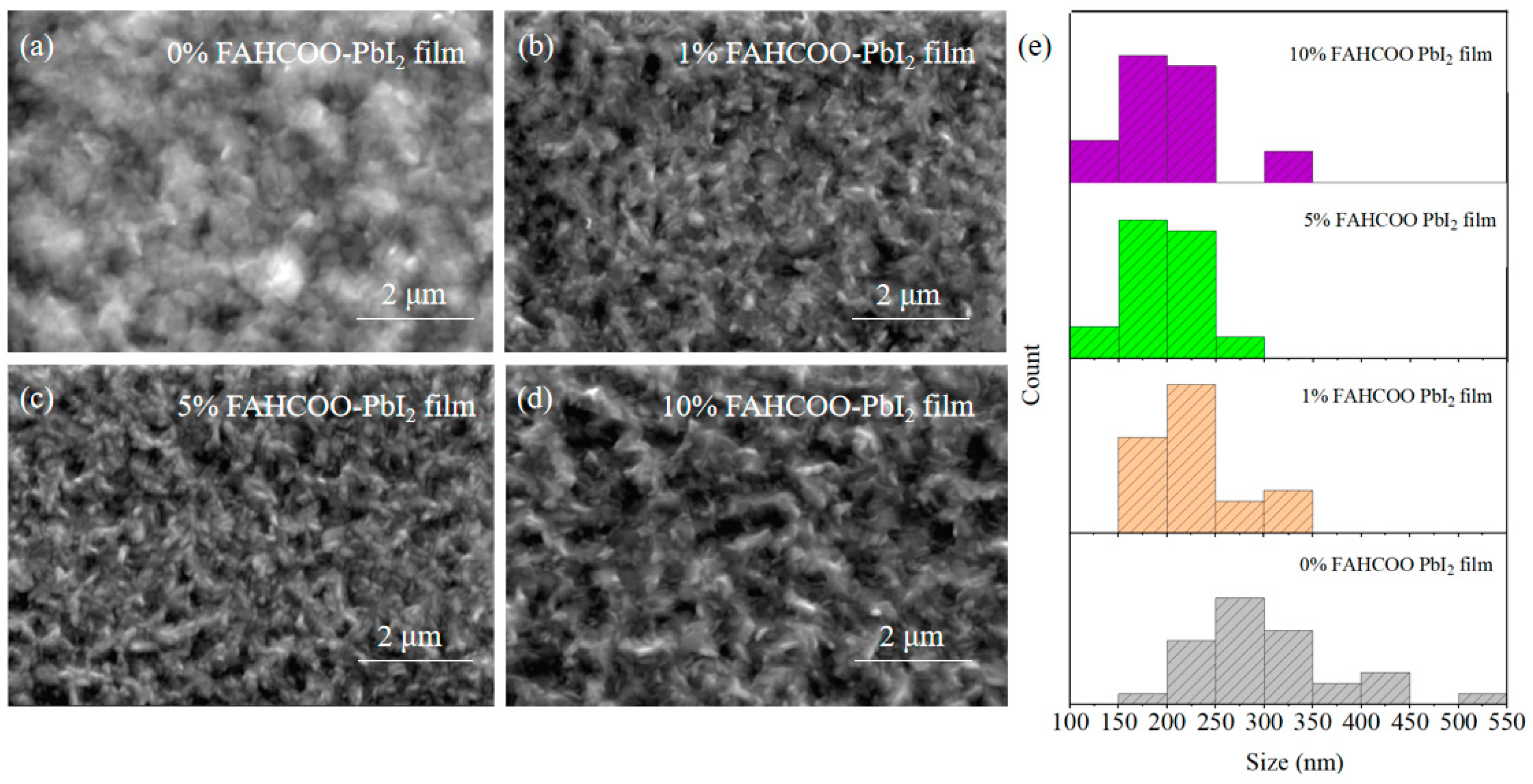
We added different concentrations of FAHCOO (0%, 1%, 5%, 10%) to a PbI2 precursor solution. Then, in the first step of the spin-coating preparation, PbI2 film was formed by heating at 70 °C for 1 min after 30 s of spin-coating the solution at 2500 r/min. These groups of PbI2 films with different concentrations of FAHCOO additives were characterized using SEM, and characterization results are shown in Figure 2. The average diameters of PbI2-grains were ≈301, ≈225, ≈198, and ≈200 nm for PbI2 film with FAHCOO concentrations of 0%, 1%, 5%, and 10%, respectively. The results showed that the addition of FAHCOO could decrease the grain size of PbI2 films. This inhibition effect saturated when the amount of FAHCOO exceeded 5%.
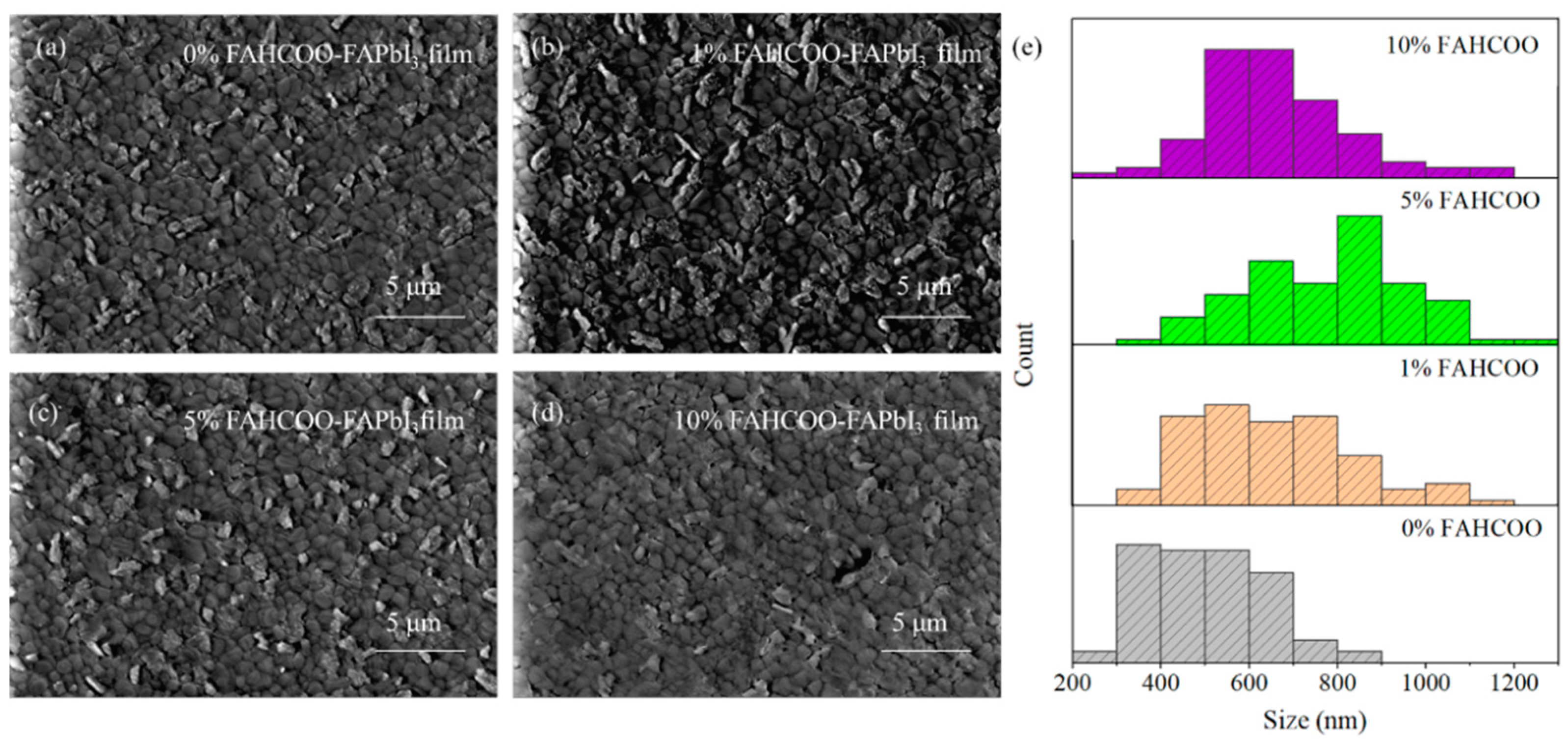
SEM characterizations of FAPbI3 perovskite films were than analyzed and a two-step spin coating method was carried out. After preparing PbI2 films with different concentrations (0%, 1%, 5%, 10%) of FAHCOO additives, FAPbI3 perovskite films were prepared during the second step of spin coating onto the PbI2 films. These groups of perovskite films were characterized using SEM, and the characterization results are shown in Figure 3. The average diameters of FAPbI3-grains were ≈500, ≈652, ≈783, and ≈662 nm for the FAPbI3 films with FAHCOO concentrations of 0%, 1%, 5%, and 10%, respectively. From these results, we can conclude that the addition of FAHCOO caused the grain size enlargement of the FAPbI3 perovskite films and the reduction of the white FAI residual particles on the films’ surface. There may be two reasons for this: First, the FAHCOO was added to the PbI2 precursor solution, which inhibited crystallization nucleation of PbI2 films. In turn, the smaller PbI2 grains made FAI and PbI2 undergo a more completely rotational stacking diffusion reaction when producing FAPbI3. Second, HCOO− can be strongly coordinated with Pb2+, so it can coordinate with the excess Pb2+ in the PbI2 solution to form an intermediate. In the second step of the spin coating reaction, the Pb2+ in the intermediate needs to exchange HCOO− with I− before it can continue to react with FAI and form FAPbI3. This also delays the crystallization of FAI; therefore, the reaction was more sufficient, the crystal quality was better, and the quality of the generated FAPbI3 perovskite films was improved. As the concentration amount increased from 0% to 5%, the size of the grains on the films increased in turn. Consequently, the grain size increased most obviously when the concentration amount reached 5%. When the added concentration amount increased to 10%, the film appeared to have a smaller grain size than the film with the 5% FAHCOO addition, and the grain size was more uneven. This maybe due to the excess formamidine residue on the surface of the PbI2 film with the 10% FAHCOO addition, which existed in the form of impurities. This was not conducive to the full reaction between PbI2 and FAI in the second step of spin coating.
3.2. XRD Characterization of Formamidine Formate-Doped FAPbI3 Perovskite Layer Films
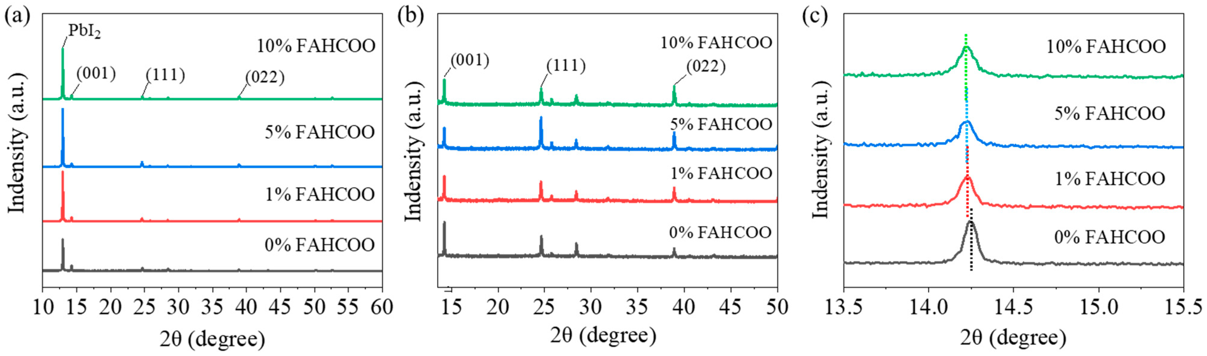
We carried out XRD characterization of FAPbI3 perovskite films prepared with different amounts of FAHCOO (0%, 1%, 5%, 10%) to test their crystallinity. Characterization results are shown in Figure 4. Figure 4a shows the diffraction peak of residual PbI2 at 12.94° and main diffraction peaks of the generated α-FAPbI3 phase in the (001), (111), and (002) lattice planes. By observing the diffraction peaks of PbI2, we found that the FAPbI3 films doped with FAHCOO had a higher diffraction peak height than the PbI2 films without FAHCOO. The diffraction peak heights of PbI2 films prepared with different amounts of FAHCOO were similar, which indicated that the residual amount of PbI2 increased after the addition of FAHCOO, while the additive volume of FAHCOO had little effect on the residual amount of PbI2.
It can be seen from Figure 4 that a large amount of lead iodide remained in the perovskite films. During the operational process of the devices, a small amount of lead iodide residue is beneficial as it passivates interface defects and improves the stability of devices. Due to the strong lead iodide peak, we enlarged the main diffraction peak of α-FAPbI3 in Figure 4a, as shown in Figure 4b, in order to compare the crystallinity of FAPbI3 films. The α-FAPbI3 perovskite films had three main diffraction peaks: the (001) plane at 14.25°, the (111) plane at 24.66°, and the (002) plane at 28.41°. From Figure 4b, it can be seen that the peak heights of the FAPbI3 films with FAHCOO added were higher than the FAPbI3 films without FAHCOO at (111) and (022). Conversely, the peak heights in (001) were slightly decreased. In general, the intensities of the diffraction peaks did not differ much. We magnified the diffraction peak of the (001) crystal plane, as shown in Figure 4c, it can be observed that the diffraction peak shifted to the left after the addition of FAHCOO. This indicates that the FAHCOO was successfully incorporated into the perovskite lattice, which increased the lattice constant of FAPbI3 and, as a result, the diffraction peak of α-FAPbI3 shifted to the left. Then we performed a Gaussian fitting calculation on the diffraction peaks of the (111) crystal plane to obtain the full width at half maximum (FWHM) of the diffraction peaks of the films with different concentration amounts of FAHCOO. We found that the FWHM of 0%, 1%, 5%, and 10% were 0.13079, 0.14658, 0.09234, and 0.14567, respectively. As a smaller FWHM corresponds to higher crystallinity, this result indicated that the crystallization of perovskite films was improved with the addition of FAHCOO. One could speculate that FAHCOO in the PbI2 precursor inhibited the grain size of the PbI2 films, making the second-step crystallization reaction more sufficient. In addition, HCOO− and excess Pb2+ formed an intermediate that introduced an ion exchange process, which also delayed the crystallization process of FAPbI3 films; thereby, improving the film quality of the perovskite.
It is worth noting that the introduction of 5% FAHCOO significantly increased the crystallinity of FAPbI3 films at (111) in the crystal plane. We speculate that FAHCOO in the PbI2 precursor reacts with PbI2 and generates (111) oriented FAPbI3, thus providing crystal seeds for the second-step reaction between FAI and the PbI2 film. These (111) oriented seeds act as a template during the crystallization of FAPbI3 films; thereby, inducing the formation of (111) preferentially oriented perovskite films. For FAHCOO doping concentrations of 1% and 10%, the grain size shows no obvious change. For the former, the addition of 1% was too small resulting in a nonuniform doping in the whole perovskite lattice, which, in turn, resulted in phase separation. For the latter, the addition of 10% was too much, which may have introduced serious impurities into the surface of the PbI2 film and suppressed the reaction between the PbI2 and FAI.
3.3. Effect of Formamidine Formate on Photoelectric Properties of Devices
We tested the J–V curves of FAPbI3 PSC devices with different molar amounts (0%, 1%, 5%, 10%) of FAHCOO to compare the effects of different molar ratios of FAHCOO on the performance of FAHCOO devices. The specific J–V curve is shown in Figure 5a and the corresponding photovoltaic performance parameters are shown in Table 1. By comparison, we found that after the initial addition of 1% FAHCOO, the PCE of the FAPbI3 PSC device was slightly decreased compared to the control device without FAHCOO. We speculated that this may be due to the addition of too little FAHCOO, which led to the observation that the FAHCOO doped in FAPbI3 cannot cover the film surface evenly, which results in phase separation and then a decrease in PCE. When the concentration amount of FAHCOO was increased to 5%, the optoelectronic performances of the devices were comprehensively improved, and PCE reached the best performance at 19.04%. This was a significant improvement compared with the control device performance of 16.69%. Therefore, it can be concluded that the 5% mole ratio is the optimal concentration. When the concentration amount was increased to 10%, we found that although the device with 10% FAHCOO improved across various optoelectronic performance parameters compared with the device without FAHCOO, the PCE was lower than the optimal device which used a 5% concentration. This may be due to an excessive addition of FAHCOO, which took the form of impurities on the surface of PbI2 films. This made the surface of the PbI2 films less uniform and compact, which is not conducive to the full reaction of PbI2 and FAI to form FAPbI3. Figure 5b shows the PCE distributions of over 40 devices fabricated using FAPbI3 with different amounts of FAHCOO. The results are consistent with Figure 5a and Table 1. The PCE distribution of the PSC with 5% FAHCOO was wider than others, which may be the result of an immature process. In follow-up work, the process will be further optimized to improve the reproducibility of the devices.
3.4. Stability of PSC Devices
To investigate whether FAHCOO has an effect on the stability of FAPbI3 devices in an air environment, we tested the long-term stability of the FAPbI3 device with the optimal 5% addition concentration of FAHCOO and the original FAPbI3 device without FAHCOO in a glove box with an air atmosphere, controlled room temperature, and a constant humidity of 6%. The PCE of devices were tested every 50 h, and we recorded the relationship between the normalized PCE and time, as shown in Figure 5c. After a 200 h test, the normalized PCE of the FAPbI3 device with 5% FAHCOO dropped to about 98% of the initial efficiency, while the normalized PCE of the controlled device without FAHCOO dropped to about 95.6% of its initial efficiency. This result indicates that the long-term stability of the FAPbI3 device in the air environment had been improved after the addition of FAHCOO.
Then we tested the operational stability of FAPbI3 devices prepared with the optimal 5% concentration of FAHCOO and the original FAPbI3 devices without FAHCOO to study the influence of FAHCOO on the operational stability of the prepared FAPbI3 devices. Through the tracking test of the MPP under a standard sunlight of AM1.5G, we observed a relationship between the normalized PCE of the FAPbI3 device at the MPP and time, as shown in Figure 5d. The normalized PCE of the FAPbI3 device with 5% FAHCOO remained at 100% after a 4100 s MPP tracking test, while the normalized PCE of the original FAPbI3 device without FAHCOO dropped to about 94% after a 4100 s MPP tracking test. The operational stability of the prepared FAPbI3 device was improved after the addition of FAHCOO, which may be attributed to the reduction of defects in the FAPbI3 device with FAHCOO.
4. Conclusions
In this paper, the effect of the FAHCOO on the quality of the FAPbI3 films prepared using a two-step spin coating method and the corresponding device performance was investigated by adding FAHCOO to the PbI2 precursor. FAHCOO could passivate iodide vacancy defects in the FAPbI3 films and could introduce an ion exchange process that delays the crystallization during film preparation. Moreover, by adding the 5% optimal concentration of FAHCOO to the PbI2 precursor solution, the FAPbI3 templates can be pregenerated, thereby inducing the growth of the (111) crystal plane in the second step reaction. This also increases the grain size of the generated FAPbI3, thereby improving the crystallinity of the film. For the above reasons, the surface morphology and crystallinity of the films were successfully improved, and the photoelectric performance and stability of corresponding devices were also improved. Among the improvements, the PCE of the device improved from 16.69% to 19.04% when 5% FAHCOO was added. The long-term stability and the operational stability of the device with 5% FAHCOO was also improved. Specifically, for the long-term stability test, the PCE dropped to about 98% of the initial efficiency after being placed in the air environment for 200 h, and the original control device dropped to about 95.6%. In terms of operational stability, after 4100 s of simulated sunlight exposure, the optimized device with 5% FAHCOO maintained nearly 100% of its initial efficiency, while the original control device dropped to about 94%.
Author Contributions
Conceptualization, J.W. and Z.G.; experiment, Z.G.; software, X.S.; validation, L.Z., and X.S.; investigation, J.W.; data curation, Z.G.; writing—original draft preparation, Z.G.; writing—review and editing, J.W.; supervision, H.L.; project administration, K.X.; funding acquisition, J.W., K.X. and H.L. All authors have read and agreed to the published version of the manuscript.
Funding
This research was funded by by the National Natural Science Foundation of China (No. 22005034, 22105018, 22179009) and the National Key R&D Program of China (No. 2019YFB1803504).
Conflicts of Interest
The authors declare no conflict of interest.
References
- Park, N.-G. Perovskite solar cells: An emerging photovoltaic technology. Mater. Today 2015, 18, 65–72. [Google Scholar] [CrossRef]
- Jung, H.S.; Park, N.-G. Perovskite Solar Cells: From Materials to Devices. Small 2015, 11, 10–25. [Google Scholar] [CrossRef] [PubMed]
- Wang, Y.; Zhang, Y.B.; Zhang, P.H.; Zhang, W.Q. High intrinsic carrier mobility and photon absorption in the perovskite CH3NH3PbI3. Phy. Chem. Chem. Phys. 2015, 17, 11516–11520. [Google Scholar] [CrossRef] [PubMed]
- Chouhan, A.S.; Jasti, N.P.; Hadke, S.; Raghavan, S.; Avasthi, S. Large grained and high charge carrier lifetime CH3NH3PbI3 thin-films: Implications for perovskite solar cells. Curr. Appl. Phys. 2017, 17, 1335–1340. [Google Scholar] [CrossRef]
- Wang, B.H.; Xiao, X.D.; Chen, T. Perovskite photovoltaics: A high-efficiency newcomer to the solar cell family. Nanoscale 2014, 6, 12287–12297. [Google Scholar] [CrossRef]
- Park, N.-G.; Zhu, K. Scalable fabrication and coating methods for perovskite solar cells and solar modules. Nat. Rev. Mater. 2020, 5, 333–350. [Google Scholar] [CrossRef]
- Kojima, A.; Teshima, K.; Shirai, Y.; Miyasaka, T. Organometal Halide Perovskites as Visible-Light Sensitizers for Photovoltaic Cells. J. Am. Chem. Soc. 2009, 131, 6050–6051. [Google Scholar] [CrossRef]
- Min, H.; Lee, D.Y.; Kim, J.; Kim, G.; Lee, K.S.; Kim, J.; Paik, M.J.; Kim, Y.K.; Kim, K.S.; Kim, M.G.; et al. Perovskite solar cells with atomically coherent interlayers on SnO2 electrodes. Nature 2021, 598, 444–450. [Google Scholar] [CrossRef]
- Noh, J.H.; Im, S.H.; Heo, J.H.; Mandal, T.N.; Seok, S.I. Chemical Management for Colorful, Efficient, and Stable Inorganic–Organic Hybrid Nanostructured Solar Cells. Nano Lett. 2013, 13, 1764–1769. [Google Scholar] [CrossRef]
- Eperon, G.E.; Stranks, S.D.; Menelaou, C.; Johnston, M.B.; Herz, L.M.; Snaith, H.J. Formamidinium lead trihalide: A broadly tunable perovskite for efficient planar heterojunction solar cells. Energy Environ. Sci. 2014, 7, 982–988. [Google Scholar] [CrossRef]
- Yuan, Y.B.; Huang, J.S. Ion Migration in Organometal Trihalide Perovskite and Its Impact on Photovoltaic Efficiency and Stability. Acc. Chem. Res. 2016, 49, 286–293. [Google Scholar] [CrossRef] [PubMed]
- Chen, B.; Rudd, P.N.; Yang, S.; Yuan, Y.B.; Huang, J.S. Imperfections and their passivation in halide perovskite solar cells. Chem. Soc. Rev. 2019, 48, 3842–3867. [Google Scholar] [CrossRef]
- Azpiroz, J.M.; Mosconi, E.; Bisquert, J.; De Angelis, F. Defect migration in methylammonium lead iodide and its role in perovskite solar cell operation. Energy Environ. Sci. 2015, 8, 2118–2127. [Google Scholar] [CrossRef]
- Tress, W.; Marinova, N.; Moehl, T.; Zakeeruddin, S.M.; Nazeeruddin, M.K.; Grätzel, M. Understanding the rate-dependent J–V hysteresis, slow time component, and aging in CH3NH3PbI3 perovskite solar cells: The role of a compensated electric field. Energy Environ. Sci. 2015, 8, 995–1004. [Google Scholar] [CrossRef]
- Kang, D.H.; Park, N.G. On the Current–Voltage Hysteresis in Perovskite Solar Cells: Dependence on Perovskite Composition and Methods to Remove Hysteresis. Adv. Mater. 2019, 31, 1805214. [Google Scholar] [CrossRef] [PubMed]
- Slotcavage, D.J.; Karunadasa, H.I.; McGehee, M.D. Light-Induced Phase Segregation in Halide-Perovskite Absorbers. ACS Energy Lett. 2016, 1, 1199–1205. [Google Scholar] [CrossRef]
- Kim, S.; Bae, S.; Lee, S.-W.; Cho, K.; Lee, K.D.; Kim, H.; Park, S.; Kwon, G.; Ahn, S.W.; Lee, H.M.; et al. Relationship between ion migration and interfacial degradation of CH3NH3PbI3 perovskite solar cells under thermal conditions. Sci. Rep. 2017, 7, 1200. [Google Scholar] [CrossRef]
- Carrillo, J.; Guerrero, A.; Rahimnejad, S.; Almora, O.; Zarazua, I.; Mas-Marza, E.; Bisquert, J.; Garcia-Belmonte, G. Ionic reactivity at contacts and aging of methylammonium lead triiodide perovskite solar cells. Adv. Energy Mater. 2016, 6, 1502246. [Google Scholar] [CrossRef]
- Hassan, A.; Wang, Z.; Ahn, Y.H.; Azam, M.; Khan, A.A.; Farooq, U.; Zubair, M.; Cao, Y. Recent defect passivation drifts and role of additive engineering in perovskite photovoltaics. Nano Energy 2022, 101, 107579. [Google Scholar] [CrossRef]
- Niu, T.T.; Chao, L.F.; Dong, X.; Fu, L.; Chen, Y.H. Phase-Pure α-FAPbI3 for Perovskite Solar Cells. J. Phys. Chem. Lett. 2022, 13, 1845–1854. [Google Scholar] [CrossRef]
- Azam, M.; Khan, A.A.; Liang, G.-X.; Li, G.-J.; Chen, S.; Zheng, Z.-H.; Farooq, U.; Ishaq, M.; Fan, P.; Wang, Z.; et al. Examining the Interfacial Defect Passivation with Chlorinated Organic Salt for Highly Efficient and Stable Perovskite Solar Cells. Sol. RRL 2020, 4, 2000358. [Google Scholar] [CrossRef]
- Akin, S.; Akman, E.; Sonmezoglu, S. FAPbI3-Based Perovskite Solar Cells Employing Hexyl-Based Ionic Liquid with an Efficiency Over 20% and Excellent Long-Term Stability. Adv. Funct. Mater. 2020, 30, 2002964. [Google Scholar] [CrossRef]
- Jeong, J.; Kim, M.; Seo, J.; Lu, H.; Ahlawat, P.; Mishra, A.; Yang, Y.; Hope, M.A.; Eickemeyer, F.T.; Kim, J.Y.; et al. Pseudo-halide anion engineering for α-FAPbI3 perovskite solar cells. Nature 2021, 592, 381–385. [Google Scholar] [CrossRef] [PubMed]
Figure 1.
(a) Chemical structure of FAHCOO. (b) Device structure diagram of an FAPbI3 solar cell. (c,d) Schematic diagram of an FAPbI3 perovskite without (c) or with (d) FAHCOO passivation.
Figure 1.
(a) Chemical structure of FAHCOO. (b) Device structure diagram of an FAPbI3 solar cell. (c,d) Schematic diagram of an FAPbI3 perovskite without (c) or with (d) FAHCOO passivation.

Figure 2.
SEM comparison image of PbI2 films prepared with different amounts of FAHCOO. (a) 0% FAHCOO PbI2 film. (b) 1% FAHCOO PbI2 film. (c) 5% FAHCOO PbI2 film. (d) 10% FAHCOO PbI2 film. (e) Diameters statistical diagrams of grains of PbI2 films.
Figure 2.
SEM comparison image of PbI2 films prepared with different amounts of FAHCOO. (a) 0% FAHCOO PbI2 film. (b) 1% FAHCOO PbI2 film. (c) 5% FAHCOO PbI2 film. (d) 10% FAHCOO PbI2 film. (e) Diameters statistical diagrams of grains of PbI2 films.

Figure 3.
SEM comparison of FAPbI3 films prepared with different amounts of FAHCOO. (a) SEM image of 0% FAHCOO FAPbI3 film. (b) SEM image of 1% FAHCOO FAPbI3 film. (c) SEM image of 5% FAHCOO FAPbI3 film. (d) SEM image of 10% FAHCOO FAPbI3 film. (e) Diameters statistical diagrams of 85 grains of FAPbI3 films.

Figure 4.
(a) XRD diffraction patterns of FAPbI3 films with different concentration additions (0%, 1%, 5%, 10%) of FAHCOO. (b) The enlarged XRD diagram of α-FAPbI3 film from Figure 4a. (c) Enlarged image of diffraction peak of (001) crystal plane from Figure 4a.

Figure 5.
(a) Comparison of the J–V curves of the best PCE FAPbI3 devices prepared with different dosages (0%, 1%, 5%, 10%) of FAHCOO. (b) Boxplots of PCE statistics of devices based on FAPbI3 films with different doping amounts of FAHCOO. (c) Comparison of PCE changes between the FAPbI3 device with the optimal amount of FAHCOO (5%) and the undoped control FAPbI3 device in the air environment. (d) Normalized PCE change of the FAPbI3 device prepared with or without FAHCOO addition.


Table 1.
Photoelectric performance parameters of the best-efficiency FAPbI3 devices prepared with different addition amounts (0%, 1%, 5%, 10%) of FAHCOO.
Table 1.
Photoelectric performance parameters of the best-efficiency FAPbI3 devices prepared with different addition amounts (0%, 1%, 5%, 10%) of FAHCOO.
| Device | VOC (V) | JSC (mA/cm2) | FF (%) | PCE (%) |
|---|---|---|---|---|
| 0% FAHCOO | 1.03 | 23.22 | 69.49 | 16.69 |
| 1% FAHCOO | 1.01 | 21.65 | 75.27 | 16.6 |
| 5% FAHCOO | 1.05 | 24.27 | 74.95 | 19.04 |
| 10% FAHCOO | 1.06 | 23.42 | 73.44 | 18.3 |
Publisher’s Note: MDPI stays neutral with regard to jurisdictional claims in published maps and institutional affiliations. |
© 2022 by the authors. Licensee MDPI, Basel, Switzerland. This article is an open access article distributed under the terms and conditions of the Creative Commons Attribution (CC BY) license (https://creativecommons.org/licenses/by/4.0/).
Share and Cite
MDPI and ACS Style
Gan, Z.; Zhao, L.; Sun, X.; Xu, K.; Li, H.; Wei, J. Influence of Formamidine Formate Doping on Performance and Stability of FAPbI3-Based Perovskite Solar Cells. Crystals 2022, 12, 1194. https://doi.org/10.3390/cryst12091194
AMA Style
Gan Z, Zhao L, Sun X, Xu K, Li H, Wei J. Influence of Formamidine Formate Doping on Performance and Stability of FAPbI3-Based Perovskite Solar Cells. Crystals. 2022; 12(9):1194. https://doi.org/10.3390/cryst12091194
Chicago/Turabian StyleGan, Zhenyu, Lu Zhao, Xiangyu Sun, Kun Xu, Hongbo Li, and Jing Wei. 2022. "Influence of Formamidine Formate Doping on Performance and Stability of FAPbI3-Based Perovskite Solar Cells" Crystals 12, no. 9: 1194. https://doi.org/10.3390/cryst12091194
Note that from the first issue of 2016, this journal uses article numbers instead of page numbers. See further details here.