Article

Dual-Mechanism Absorptive Metasurface with Wideband 20 dB RCS Reduction

Department of Electronic Science, College of Electronic Science and Technology, National University of Defense Technology, Changsha 410073, China
*
Author to whom correspondence should be addressed.
Crystals 2022, 12(4), 493; https://doi.org/10.3390/cryst12040493
Submission received: 3 March 2022 / Revised: 29 March 2022 / Accepted: 31 March 2022 / Published: 2 April 2022
(This article belongs to the Special Issue Active Hybrid Soft Metamaterials)

Abstract

:
This paper presents a dual-mechanism method to design a single-layer absorptive metasurface with wideband 20 dB RCS reduction by simultaneously combining the absorption and phase cancellation mechanisms. The metasurface comprises two kinds of absorbing unit cells with 10 dB absorption performance but different reflection phases. The impedance condition for 20 dB RCS reduction is theoretically analyzed considering both the absorption and the phase cancellation based on the two unit cells, and the relationship between the surface impedance and the reflection phase/amplitude is revealed. According to these analyses, two unit cells with absorption performance and different reflection phases are designed and utilized to realize the absorptive metasurface. Numerical and experimental results show that the single-layer absorptive metasurface features wideband 20 dB RCS within 11.5–16 GHz with a thickness of only 3 mm.

1. Introduction

Metasurface, a two-dimensional (2D) metamaterial with low profile, has attracted increasing attention in recent years due to its brand-new electromagnetic (EM) characteristic, designable material parameters, low planar profiles, easy on-chip fabrication, and extraordinary capability and flexibility to tailor EM waves [1,2,3,4,5,6,7,8,9,10]. By virtue of these good features, metasurfaces have also been intensively employed for RCS reduction. Phase cancellation [11,12,13,14,15,16,17,18,19] and absorption [20,21,22,23,24,25,26,27] are the two well-known mechanisms to reduce the radar cross section (RCS) by the metasurface.
The phase cancellation mechanism of the metasurface is a spatial domain RCS reduction method that is to properly design the reflection phase of each unit cell, realize phase cancellation or phase gradient, and then control the reflected wave beam distribution. The state-of-the-art approaches are mainly based on the chessboard distribution phase cancellation metasurfaces [11,12,14,15] and the optimized coded metasurfaces [16,17,18,19]. The traditional chessboard metasurfaces redirect the reflected wave into four symmetrical beams, making the reflection amplitude highly suppressed in the monostatic direction. The optimized coding metasurfaces shape the reflected wave with approximately uniform echo intensity in all directions, which can also achieve RCS reduction. The absorption mechanism of the metasurface is a method to reduce the RCS in the energy domain, which mainly utilizes the lossy property of the unit cell. The absorbing metasurface can be divided into various forms, including resistive loss, dielectric loss, and magnetic loss [27,28,29,30].
Some researchers use both cancellation and absorption to reduce RCS [31,32,33,34,35,36]. In [31], the absorption occurs in low frequency using lumped resistors. The cancellation diffusion occurs in high frequency by constructing random phase distribution, resulting in the dual-band 8 dB RCS reduction. In [32], metasurfaces with multiple layers that operate phase cancellation and absorption are proposed to achieve dual-mechanism and obtain 10 dB RCS reduction from 1.55 to 19.2 GHz, respectively. Similarly, Ref. [33] demonstrates a double-layered metasurface to acquire wideband RCS reduction by introducing both phase cancellation and absorption. It should be noted that almost all the works above focus on the expansion of reduction bandwidth using the dual-mechanism but fail to explore the possibility of realizing a lower RCS index. In [36], the absorption is introduced into phase diffusion metasurface to broaden the 10 dB RCS reduction, but fail to achieve lower 20 dB reduction.
Wider band and deeper RCS reduction by lower profile are always the main concerns of stealth material research. Though the above two RCS reduction mechanisms have made significant progress in expanding bandwidth, most researchers design and measure RCS reduction bandwidth with 10 dB standard, that is, the return energy is reduced by 90%. With the rapid development of radar detection technology, the 10 dB RCS reduction can no longer meet the stealth requirements.
A dual-mechanism absorptive metasurface with 20 dB RCS reduction by combining both the phase cancellation and absorption mechanisms is proposed in this paper. Utilizing the reflection phase difference between two absorbing unit cells, we organically combine the absorbing and phase cancellation mechanism to reduce the intensity of the backward echo in both the energy domain and the spatial domain. By optimizing the number of two unit cells, an absorptive metasurface is composed to implement RCS reduction above 20 dB. Numerical and experimental results confirm that the dual-mechanism absorptive metasurface manifests wideband, robustness, and much lower RCS. Compared to current methods, our strategy can broaden the 20 dB reduction bandwidth while keeping that of the original 10 dB almost unchanged, promising great potentials in real applications.

2. Design Principle of Metasurface

Suppose a metasurface, which consists of M × N unit cells, is under the normal incidence of a plane wave, as shown in Figure 1. The conception of RCS reduction can be explained by the principle of planar array theory [32]. For a metasurface composed of two different unit cells, which is the simplest case for cancellation layout, the monostatic RCS reduction of metasurface can be represented by:
RCS r = 20 log   | α   A 1 e j φ 1 + ( 1 α )   A 2 e j ( φ 1 φ d ) |
Here, A1 and A2 represents the amplitude of the reflected EM waves of unit cells “1” and “2”. Parameter α is the ratio of two unit cells and α = n 1 n 1 + n 2 , 1 α = n 2 n 1 + n 2 , where n 1 is the number of unit cell “1” in whole metasurface while n 2 is that of unit cell “2”. The phase difference of two unit cells is φ d , which can be expressed as:
φ d = φ 1 φ 2
φ 1 and φ 2 are the reflection phases of “1” and “2”, respectively.
If “1” and “2” have no absorption and all energy is reflected, then A1 = A2 = 1. The relationship between RCS reduction and parameter α , φ d can be expressed by Figure 2. The maximum range of φ d appears at α = 0.5. In order to obtain 10 dB RCS reduction, the phase difference needs to be at (180° − 37°, 180° + 37°), which is consistent with the conclusion of AMC chessboard [14]. For RCS reduction above 20 dB, the phase difference needs to be at (180° − 11°, 180° + 11°). However, for the resonance phase, it is an extremely harsh constraint for two unit cells to meet the phase difference of 180° ± 11°. Therefore, the reduction effect using phase cancellation, which could get more than 20 dB RCS reduction, is only for individual frequency points. If “1” has 10 dB absorption property while “2” is lossless (A1 = 0.316, A2 = 1), the relationship can be expressed by Figure 3a. The 20 dB maximum range of φ d appears at α = 0.78 from 180°− 24° to 180° + 24°, which is wider than 180° ± 11°. If “1” and “2” both have 10 dB absorption property (A1 = A2 = 0.316) (see Figure 3b), the 20 dB maximum range of φ d appears at α = 0.5 and the range from 180° − 37° to 180° + 37°, which is wider than 180° ± 11°.
To sum up, absorption can help to expand the range of φ d of specific RCS reduction value, and the α is 0.5 when absorption ability of “1” and “2” are the same. When the absorption coefficient is unequal, the α will move to an off-center position. The degree of deviation increases with the increase in absorption coefficient difference.

3. Results and Discussion

3.1. Unit Cell Design

Based on the equivalent transmission line method, a single-layer reflected unit cell, which is an infinite periodic structure in free space (see Figure 4a), can be equivalent to a single-port transmission-line network.
As shown in Figure 4b, Zr and Zd denote the equivalent impedance of the periodic structure and the substrate layer, respectively. Zr is a complex value that can be expressed by Zr = R + jX. Zin is the input impedance of this network. The reflection coefficient of the unit cell can be expressed as
Γ = Z i n Z 0 Z i n + Z 0
And
Z i n = Z r / / j Z d tan ( β d d )
Z d = Z 0 / ε r
where Z0 is the intrinsic impedance of a vacuum, d and ε r are the thickness and relative permittivity of the substrate layer, respectively. Thus, the reflection amplitude and phase can be expressed as
A = | Γ |
φ = a r c t a n ( I m   ( Γ ) R e   ( Γ ) )
Here, we fix d = 3 mm, ε r = 3, and the center frequency is set to be 13 GHz. The relationship among A , φ , R, and X can be shown in Figure 5. The black line indicates the phase of the unit cell, and the color map is the reflection amplitude. White dotted line represents reflection amplitude A = −10 dB. Therefore, we can select the points inside the white dotted circle to design the unit cells with proper phase and absorption accordingly.
However, for two different unit cells “1” and “2”, there are eight interrelated parameters, namely A1, A2, P1, P1, X1, X2, R1, R2. It is complex and time-consuming to optimize and select the eligible two unit cells. Thus, to simplify the process, we firstly design one absorption unit cell “1” and then choose the other counterpart.
According to the pre-defined parameters, the optimized topology of the absorbed “1” is shown in Figure 6a. It is a single-layer structure composed of top compound resistive film, a middle dielectric spacer, and a backed metallic ground. The top compound resistive film patterns are two square rings, which can offer two resonance points at the given frequency band. The resistive film will add resistive loss at these two frequencies which ensure the wideband absorption. In addition, the fourfold rotation symmetry makes the unit cells polarization insensitive. Additionally, the stable wideband reflection phase difference by varied dimensions has been verified in ref. [16]. The resistive film can offer R and X simultaneously for 10 dB absorption, as shown in Figure 5. In the current design, the F4BM-1 substrate with permittivity of 3, a1 = 5 mm, b1 = a1 − 3 mm, the height of h = 3 mm and dielectric loss of tan δ = 0.00081 is utilized as the dielectric spacer. For “1”, the sheet resistance of resistive film patterns is 10 Ω/sq, and the reflection phase and amplitude curves are shown in Figure 6b. The 10 dB absorption bandwidth is 9.9–17.5 GHz, but that of 20 dB is only 10.9–12.2 GHz.
Actually, the double square ring pattern is not the only choice. Any pattern has above features can play the role as unit cell. In this paper, our research attempts to provide a design recipe of whole metasurface instead of the unit cells. The unit cells we utilized are as an example to verify the effectiveness of our design recipe. Thus, we have not done too much of a complex design on the structure pattern and optimization on the performance of the unit cell.
Here, we need to confirm the design priority between absorption ability and the desired phase because these two indicators are difficult to be satisfied meanwhile for “2”. Suppose “2” has 10 dB absorption but no phase difference with “1”, a metasurface composed by “1” and “2” will only have 10 dB RCS reduction. While if “2” has no absorption but 180° phase difference with “1”, just like the situation shown in Figure 3a, the metasurface composed by these two cells will reach 20 dB RCS reduction and more. Thus, the phase difference is the key indicator than absorption for “2”. It does not mean that the absorption ability is of no use. The absorption ability will expand the phase range of 20 dB RCS reduction, which could get the wideband bandwidth.
In order to obtain the structural parameters of “2” that meet the phase difference and absorption conditions, the impedance analysis of two square resistive film rings is carried out utilizing the CST de-embedding simulation. The curves of real part R and imaginary part X of Zr are shown in Figure 7. When the sheet resistance value remains unchanged and only the length of the outer square ring varies, the curves of the real part R are almost overlapped, but the imaginary part X varies obviously. In another case, when the parameter a remains unchanged, and only the sheet resistance value varies, an opposite result will happen. Thus, according to the rule shown in Figure 7 and the relationship shown in Figure 5, unit cell “2” that meets the phase and absorption requirements can be designed.
Through the above analysis and further parameter optimization and scanning, unit cell “2” is obtained, and the topology is shown in Figure 6c. It has a similar structure to “1” but its sheet resistance and the dimension of resistive film patterns are different. The sheet resistance of resistive film patterns in “2” is 30 Ω/sq. The reflection phase and amplitude curves of “2” are shown in Figure 6d. As shown in Figure 6d, the unit cell 2 shows a relatively narrow absorption bandwidth, and the 10 dB bandwidth is only 11.8–16.3 GHz. On the other hand, the phase response curve is approximately linear, which can get a stable phase difference with “1”. The phase difference between “1” and “2” maintains about 180° from 11.5–15.5 GHz, see Figure 8.

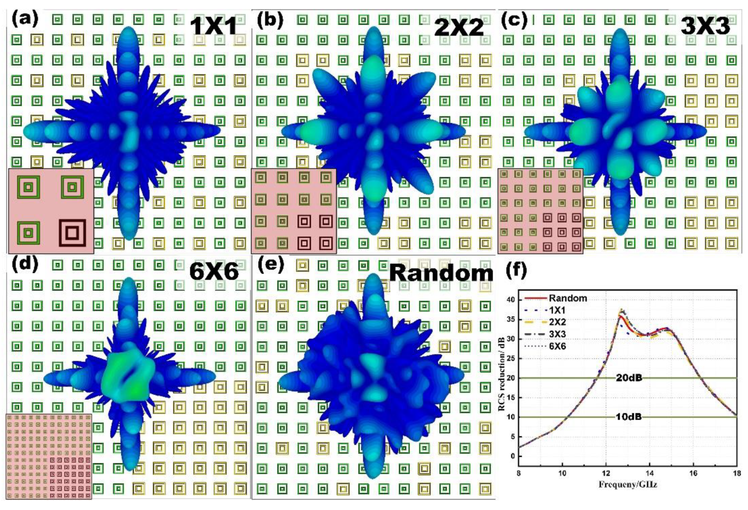
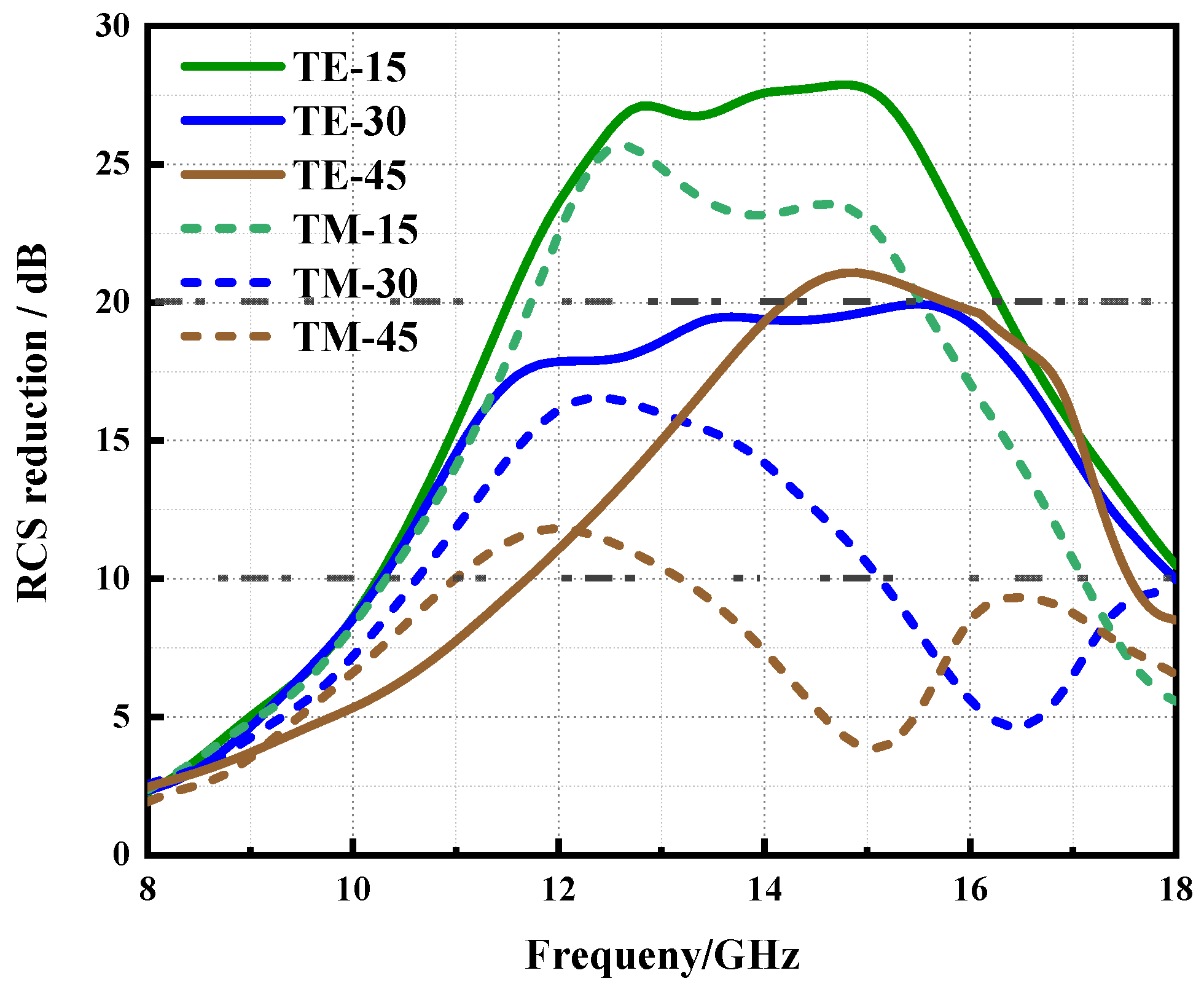
3.2. Metasurface Design and Simulation

According to Equation (1) and Figure 3a, the varied absorption ability of unit cells at different frequencies will make the maximum range of φ d deviate. At each specific frequency, there is a maximum range of φ d related to the reflection amplitude of “1” and “2”, see Figure 9a–c. To find the optimal ratio α of the whole metasurface in the wideband frequency, we need to overlap the −20 dB ranges of different frequency points. Here, an example is given in Figure 9d that the overlap area is calculated by three frequency points, 12, 13 and 14 GHz. The ordinate range corresponding to the blue overlapping area is the value range of α to meet the 20 dB reduction, see shades of gray in Figure 9d. The ordinate corresponding to the maximum phase difference range is the optimal α value of these three frequency points, see the red point in Figure 9d.
In the case that the overlap area of –20 dB exists, substitute the amplitude values of the two unit cells at each frequency point from 11.5–15.5 GHz (step with 0.1 GHz), which is the frequency range that two unit cells have about 180° phase difference, and finally get the optimal α = 0.74. For simplicity, we set α = 0.75, that is to say, the ratio of the number of “1” to the number of “2” is 3:1. Thus, the simplest subarray is designed, as shown in Figure 10a. The whole metasurface is composed of 6 × 6 subarrays (12 × 12 unit cells), see Figure 10b.
To characterize the further RCS reduction behavior of the metasurface, full-wave simulations are performed in CST Microwave Studio. For sharp comparison, the equal-size PEC plane is also simulated. The RCS curves of the designed metasurface and PEC plane are shown in Figure 11a. It is easy to see the RCS of the metasurface is much lower than the equal-size PEC plane from 11–17 GHz. The RCS reduction curve is shown in Figure 11b to further illustrate the reduction ability of the designed metasurface. From Figure 11b, we can see that the above 20 dB reduction bandwidth is from 11.5–16.4 GHz, which is much wider than the surface composed only by initial unit cell “1” (10.9–12.2 GHz). Moreover, the 10 dB bandwidth is from 10.2–18 GHz, which is almost the same compared with the initial “1” (9.9–17.5 GHz). Not only the 20 dB bandwidth but also the 25 dB and even 30 dB are widened, see from Figure 11b. Without destroying the 10 dB bandwidth, the designed metasurface can get a broadband 20 dB RCS reduction. Due to the fourfold rotation symmetry feature of two unit cells, the metasurface is polarization insensitive. For verification, different polarizations (TE, TM) of incident wave are simulated in CST and the results are shown in Figure 11a. Obviously, it can be observed that the curves of different polarizations are overlapping. Thus, for the sake of simplicity, only the simulation results of TE polarization mode are given later.
To illustrate that the further lower RCS is caused by two mechanisms: energy domain absorption and spatial domain diffusion, the 3D far-field patterns are shown in Figure 12. The patterns of the surface composed only by “1” (only has absorption but no cancellation diffusion, Figure 12b), patterns of traditional chessboard cancellation metasurface (only has cancellation diffusion but no absorption, composed by two 180°-phase-difference unit cells with total reflection, Figure 12c) and patterns of PEC plane (Figure 12a) are shown for comparison. From Figure 12a,b,d, we can easily see the designed metasurface would diffuse the reflected wave in the spatial domain, which inherits the feature of phase cancellation metasurface. Additionally, the designed metasurface would reduce the amplitude of reflected wave in the energy domain, which inherits the absorption feature of “1” and “2”, see Figure 12a,c,d. These are strong evidence for the dual-mechanism work characteristics.
When the ratio α = 0.75, there is more than one arrangement of the whole metasurface. As shown in Figure 13, the subarray can also be 2 × 2, 3 × 3, 6 × 6, or random, etc. According to Equation (2), monostatic RCS at normal incidence is only related to the ratio between “1” and “2”, regardless of the specific layout. For verification, the simulated results of different layouts but the same ratio are shown in Figure 13. As we can see from Figure 13f, the value of RCS reduction is almost the same. Only the 3-D far-field patterns are different, see Figure 13a–e. Once the ratio is fixed, the monostatic RCS at normal incidence is determined, and the different layout will only affect the scattering patterns.
The scattering patterns have no influence on monostatic RCS reduction in these cases but can affect the bi-static RCS. Thus, we choose the metasurface with 1 × 1 subarrays as the final design after comprehensively comparing the performance of the above layouts. This layout has the simplest topology and satisfactory mono/bi-static RCS reduction. It should be pointed out that the current layout is caused by the different absorption abilities of “1” and “2”. For different cases, the dual-mechanism layout will vary with the different ratios α .
For illustrating the operating characteristics of oblique incidence, the simulated results of metasurface with 1 × 1 subarrays are shown in Figure 14 when illuminated by TE and TM polarized waves at 15°, 30°, 45° angles of incidence. When the incident angle is narrow, the 20 dB reduction remains obvious. As the incidence angle increases, the reduction effect becomes worse. However, the TE mode is always better than the TM mode under the same incident angle, which is consistent with the reference [37].

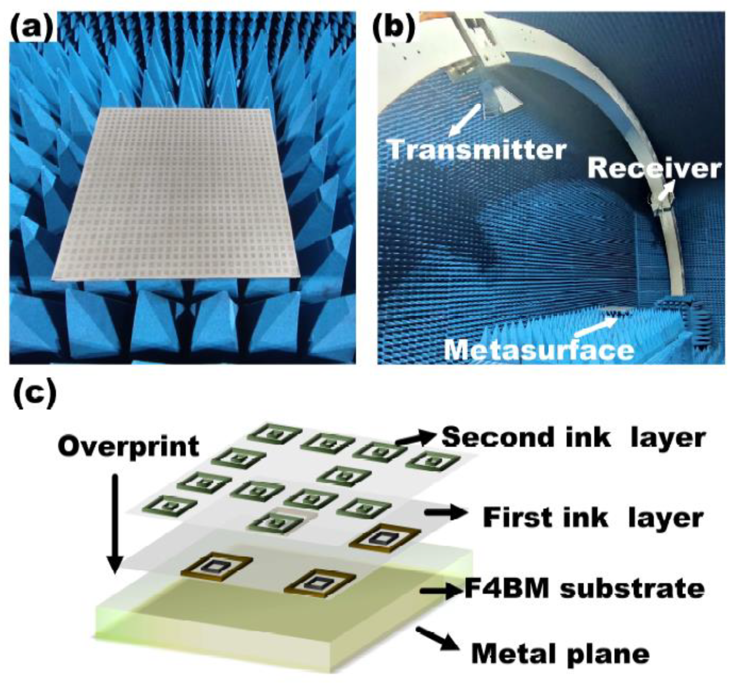
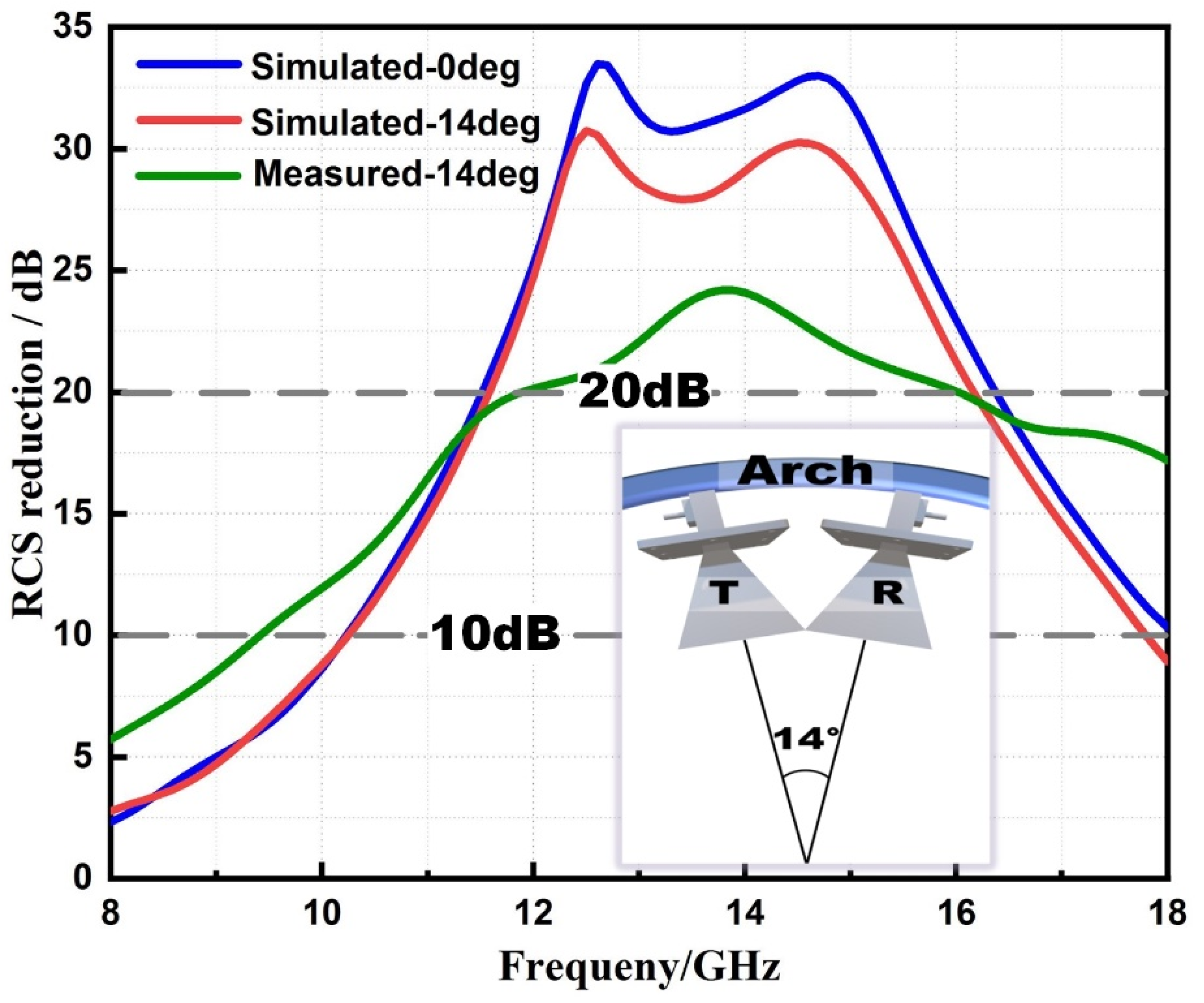
3.3. Metasurface Fabrication and Measurement

For experimental verification, a sample of the dual-mechanism absorptive metasurface is fabricated and experimentally characterized, see the photograph shown in Figure 15a. According to the standard of the test system, a sample with the size of 300 mm × 300 mm is fabricated. In this paper, we use CAPITON—900 as the resistive film in the metasurface. CAPITON—900′s is a carbon polymer thick film ink. The two carbon inks with different sheet resistance values are printed on one side of the F4BM-1 substrate by overprint technology, see Figure 15c. The RCS measurement is conducted in an anechoic chamber to avoid the disturbance of the background environment, see Figure 15b. Meanwhile, The TRL calibration technique and the time-domain gating feature of the network analyzer are used to eliminate the effects of undesirable multiple reflections.
In addition, there is a roughly 0.3 mm position error between two prints, which is the systematic error of the overprint system we used. Thus, we consider the overprint deviation during sample manufacturing and simulate the related results, see Figure 16. Suppose the “2” will be printed with 0.5 mm deviation, shown as the yellow shaded area, which is larger than 0.3 mm overprint error, and the simulated results are shown in Figure 16. We can see the RCS curves almost coincide with each other. Therefore, the errors within a certain range of fabrication cannot influence the performance of the metasurface sample. Meanwhile, it is powerful evidence that our design method has a degree of robustness.
During the monostatic RCS testing, the transmitter and the receiver must have a 14° angle in our test system, see Figure 17. For the sake of rigor, the 14° angle case is also simulated and compared with the measured 14° “monostatic RCS” results. As shown in Figure 16, the 14° simulated result curve has a similar trend with the 0° curve, only is lower from 12–16 GHz. Additionally, their 20 dB bandwidths are almost the same, from 11.7–16 GHz. The measured curve, similarly, has the approximately coincident 20 dB bandwidth compared with the 14° simulated curve. The 10 dB bandwidth of the 14° measured result is wider than the simulated one. The slight deviations at low frequency are probably attributable to the finite size effect and tolerances that are inherent in fabrications and measurements. At high frequency, the main radiation lobe of double-ridge horns antennas we used start to split. In that case, the incident wavefront is not the plane, which can generate the phase gradient on the metasurface and make the reflected energy deflected, causing the wider 10 dB bandwidth at high frequency. In addition, the differences in the numerical and experimental results are mainly caused by phase shift of metasurface sample. Since the phase is more sensitive than amplitude, a small processing error can cause a large phase change. The error in resistance film value will bring about not only impedance mismatch, but phase shift. All of the above factors along with mentioned manuscript cause the differences in the numerical and experimental results.
Otherwise, we have also tested the oblique incidence cases utilizing the arch, see Figure 18. Due to limited experimental conditions, we only measure oblique incidence in TE mode. Inevitably, the 20 dB bandwidth is deteriorating with the oblique angles increasing, but the RCS reduction still keeps the satisfactory level. Additionally, the measured results are in good agreement with the simulation results in Figure 14.

4. Conclusions

In summary, a dual-mechanism absorptive metasurface is proposed and investigated. The design method can further reduce the RCS in the energy domain by absorbing and the spatial domain by cancellation diffusion. The condition of 20 dB reduction for dual-mechanism metasurface composed with two unit cells is derived firstly. Then, we analyze the equivalent transmission line mode of the single-layer unit cell and design two absorption unit cells appropriately to meet the condition of 20 dB reduction. Finally, we determine the ratio of the two unit cells and compose the dual-mechanism structure. Numerical and experimental results show that our dual-mechanism approach has broadband 20 dB reduction ability. The expanded 20 dB bandwidth is about 11.5–16 GHz, and the 10 dB bandwidth is about 10–18 GHz. Compared with the traditional method, our method can further reduce the RCS reaching 20 dB, which can significantly compress the radar detection range. Our designed metasurface combines the two mechanisms in a single layer with only 3 mm thickness and has satisfactory oblique incident RCS reduction. Furthermore, our metasurface is immune to tiny machining errors, having a degree of robustness. All of the above features give our methods great potential in stealth applications.

Author Contributions

Conceptualization, F.Y. and Y.F.; methodology, F.Y. and Q.C.; software, Y.Z., Q.C. and F.Y.; validation, Q.C. and F.Y.; formal analysis, Q.C. and F.Y.; investigation, Y.F. and Y.Z.; resources, F.Y.; data curation, Q.C.; writing—original draft preparation, F.Y.; writing—review and editing, F.Y. and Q.C.; visualization, F.Y.; supervision, Q.C.; project administration, F.Y.; funding acquisition, Q.C. All authors have read and agreed to the published version of the manuscript.

Funding

This work was supported by National Natural Science Foundation of China (Grant 61801485); the National Natural Science Foundation of China (Grant 61901492); the National Natural Science Foundation of China (Grant 61901493); the Natural Science Foundation of Hunan Province (Grant 2020JJ5676); the science and technology innovation Program of Hunan Province (No. 2020RC2046); the science and technology innovation Program of Hunan Province (No. 2020RC2048).

Institutional Review Board Statement

Not applicable.

Informed Consent Statement

Not applicable.

Data Availability Statement

Data sharing not applicable.

Conflicts of Interest

The authors declare no conflict of interest.

References

  1. Engheta, N.; Ziolkowski, R.W. Metamaterials: Physics and Engineering Applications; John Wiley & Sons: Hoboken, NJ, USA, 2006. [Google Scholar]
  2. Holloway, C.L.; Kuester, E.F.; Gordon, J.A.; O’Hara, J.; Booth, J.; Smith, D.R. An overview of the theory and applications of metasurfaces: The two-dimensional equivalents of metamaterials. IEEE Antennas Propag. Mag. 2012, 54, 10–35. [Google Scholar] [CrossRef]
  3. Chen, H.T.; Taylor, A.J.; Yu, N. A review of metasurfaces: Physics and applications. Rep. Prog. Phys. 2016, 79, 076401. [Google Scholar] [CrossRef] [PubMed] [Green Version]
  4. Zhu, H.L.; Cheung, S.W.; Chung, K.L.; Yuk, T.I. Linear-tocircular polarization conversion using metasurface. IEEE Trans. Antennas Propag. 2013, 61, 4615–4623. [Google Scholar] [CrossRef] [Green Version]
  5. Grady, N.K.; Heyes, J.E.; Chowdhury, D.R.; Zeng, Y.; Reiten, M.T.; Azad, A.K.; Taylor, A.J.; Dalvit, D.A.; Chen, H.T. Terahertz metamaterials for linear polarization conversion and anomalous refraction. Science 2013, 340, 1304–1307. [Google Scholar] [CrossRef] [Green Version]
  6. Zheng, Y.; Zhou, Y.; Gao, J.; Cao, X.; Yang, H.; Li, S.; Xu, L.; Lan, J.; Jidi, L. Ultra-wideband polarization conversion metasurface and its application cases for antenna radiation enhancement and scattering suppression. Sci. Rep. 2017, 7, 16137. [Google Scholar] [CrossRef] [Green Version]
  7. Xu, H.X.; Tang, S.; Wang, G.M.; Cai, T.; Huang, W.; He, Q.; Sun, S.; Zhou, L. Multifunctional microstrip array combining a linear polarizer and focusing metasurface. IEEE Trans. Antennas Propag. 2016, 64, 3676–3682. [Google Scholar] [CrossRef]
  8. Li, H.; Wang, G.; Xu, H.X.; Cai, T.; Liang, J. X-band phasegradient metasurface for high-gain lens antenna application. IEEE Trans. Antennas Propag. 2015, 63, 5144–5149. [Google Scholar] [CrossRef]
  9. Huang, L.; Chen, X.; Mühlenbernd, H.; Zhang, H.; Chen, S.; Bai, B.; Tan, Q.; Jin, G.; Cheah, K.W.; Qiu, C.-W.; et al. Three-dimensional optical holography using a plasmonic metasurface. Nat. Commun. 2013, 4, 2808. [Google Scholar] [CrossRef] [Green Version]
  10. Ye, W.; Zeuner, F.; Li, X.; Reineke, B.; He, S.; Qiu, C.-W.; Liu, J.; Wang, Y.; Zhang, S.; Zentgraf, T. Spin and wavelength multiplexed nonlinear metasurface holography. Nat. Commun. 2016, 7, 11930. [Google Scholar] [CrossRef]
  11. Paquay, M.; Iriarte, J.C.; Ederra, I.; Gonzalo, R.; de Maagt, P. Thin AMC structure for radar cross-section reduction. IEEE Trans. Antennas Propag. 2007, 55, 3630–3638. [Google Scholar] [CrossRef]
  12. Galarregui, J.C.I.; Pereda, A.T.; De Falcon, J.L.M.; Ederra, I.; Gonzalo, R.; De Maagt, P. Broadband radar cross-section reduction using AMC technology. IEEE Trans. Antennas Propag. 2013, 61, 6136–6143. [Google Scholar] [CrossRef] [Green Version]
  13. Li, Y.; Zhang, J.; Qu, S.; Wang, J.; Chen, H.; Xu, Z.; Zhang, A. Wideband radar cross section reduction using two-dimensional phase gradient metasurfaces. Appl. Phys. Lett. 2014, 104, 221110. [Google Scholar] [CrossRef]
  14. Sang, D.; Chen, Q.; Ding, L.; Guo, M.; Fu, Y. Design of checkerboard AMC structure for wideband RCS reduction. IEEE Trans. Antennas Propag. 2019, 67, 2604–2612. [Google Scholar] [CrossRef]
  15. Pang, Y.; Li, Y.; Qu, B.; Yan, M.; Wang, J.; Qu, S.; Xu, Z. Wideband RCS reduction metasurface with a transmission window. IEEE Trans. Antennas Propag. 2020, 68, 7079–7087. [Google Scholar] [CrossRef]
  16. Yuan, F.; Xu, H.X.; Jia, X.Q.; Wang, G.M.; Fu, Y.Q. RCS reduction based on concave/convex-chessboard random parabolic-phased metasurface. IEEE Trans. Antennas Propag. 2020, 68, 2463–2468. [Google Scholar] [CrossRef]
  17. Xu, H.X.; Ma, S.; Ling, X.; Zhang, X.K.; Tang, S.; Cai, T.; Sun, S.; He, Q.; Zhou, L. Deterministic approach to achieve broadband polarization-independent diffusive scatterings based on metasurfaces. ACS Photonics 2018, 5, 1691–1702. [Google Scholar] [CrossRef]
  18. Al-Nuaimi, M.K.T.; Hong, W.; Whittow, W.G. Aperiodic sunflower-like metasurface for diffusive scattering and RCS reduction. IEEE Antennas Wirel. Propag. Lett. 2020, 19, 1048–1052. [Google Scholar] [CrossRef] [Green Version]
  19. Yuan, F.; Wang, G.M.; Xu, H.X.; Cai, T.; Zou, X.J.; Pang, Z.H. Broadband RCS reduction based on spiral-coded metasurface. IEEE Antennas Wirel. Propag. Lett. 2017, 16, 3188–3191. [Google Scholar] [CrossRef]
  20. Yoo, M.; Lim, S. Polarization-independent and ultrawideband metamaterial absorber using a hexagonal artificial impedance surface and a resistance-capacitor layer. IEEE Trans. Antennas Propag. 2014, 62, 2652–2658. [Google Scholar]
  21. Shen, Y.; Pang, Y.; Wang, J.; Ma, H.; Pei, Z.; Qu, S. Origamiinspired metamaterial absorbers for improving the larger-incident angle absorption. J. Phys. D Appl. Phys. 2015, 48, 445008. [Google Scholar] [CrossRef]
  22. Begaud, X.; Lepage, A.C.; Varault, S.; Soiron, M.; Barka, A. Ultrawideband and wide-angle microwave metamaterial absorber. Materials 2018, 11, 2045. [Google Scholar] [CrossRef] [PubMed] [Green Version]
  23. Liu, X.; Lan, C.; Bi, K.; Li, B.; Zhao, Q.; Zhou, J. Dual band metamaterial perfect absorber based on mie resonances. Appl. Phys. Lett. 2016, 109, 062902. [Google Scholar] [CrossRef]
  24. Shi, T.; Jin, L.; Han, L.; Tang, M.C.; Xu, H.X.; Qiu, C.W. Dispersion-engineered, broadband, wide-angle, polarization-independent microwave t metamaterial absorber. IEEE Trans. Antennas Propag. 2021, 69, 229–238. [Google Scholar] [CrossRef]
  25. Zhang, W.; Liu, Y.; Gong, S.; Wang, J.; Jiang, Y. Wideband RCS reduction of a slot array antenna using a hybrid metasurface. IEEE Trans. Antennas Propag. 2020, 68, 3644–3652. [Google Scholar]
  26. Song, J.; Wang, L.; Li, M.; Dong, J. A dual-band metamaterial absorber with adjacent absorption peaks. J. Phys. D Appl. Phys. 2018, 51, 385105. [Google Scholar] [CrossRef]
  27. Landy, N.I.; Sajuyigbe, S.; Mock, J.J.; Smith, D.R.; Padilla, W.J. Perfect metamaterial absorber. Phys. Rev. Lett. 2008, 100, 207402-1–207402-4. [Google Scholar] [CrossRef]
  28. Kowerdziej, R.; Jaroszewicz, L.R. Tunable dual-band liquid crystal based near-infrared perfect metamaterial absorber with high-loss metal. Liq. Cryst. 2019, 46, 1568–1573. [Google Scholar] [CrossRef]
  29. Marin, P.; Cortina, D.; Hernando, A. Electromagnetic wave absorbing material based on magnetic microwires. IEEE Trans. Magn. 2008, 44, 3934–3937. [Google Scholar] [CrossRef]
  30. Costa, F.; Monorchio, A.; Manara, G. Analysis and design of ultra thin electromagnetic absorbers comprising resistively loaded high impedance surfaces. IEEE Trans. Antennas Propag. 2010, 58, 1551–1558. [Google Scholar] [CrossRef] [Green Version]
  31. Zhuang, Y.; Wang, G.; Liang, J.; Zhang, Q. Dual-band low-scattering metasurface based on combination of diffusion and absorption. IEEE Antennas Wirel. Propag. Lett. 2017, 16, 2606–2609. [Google Scholar] [CrossRef]
  32. Zhou, L.; Shen, Z. Absorptive coding metasurface with ultrawideband backscattering reduction. IEEE Antennas Wirel. Propag. Lett. 2020, 19, 1201–1205. [Google Scholar] [CrossRef]
  33. Ji, C.; Huang, C.; Zhang, X.; Yang, J.; Song, J.; Luo, X. Broadband low-scattering metasurface using a combination of phase cancellation and absorption mechanisms. Opt. Express 2019, 27, 23368–23377. [Google Scholar] [CrossRef] [PubMed]
  34. Li, W.; Zhang, Y.; Wu, T.; Cao, J.; Chen, Z.; Guan, J. Broadband radar cross section reduction by in-plane integration of scattering metasurfaces and magnetic absorbing materials. Results Phys. 2019, 12, 1964–1970. [Google Scholar] [CrossRef]
  35. Zhuang, Y.; Wang, G.; Zhang, Q.; Zhou, C. Low-scattering tri-band metasurface using combination of diffusion absorption and cancellation. IEEE Access 2018, 6, 17306–17312. [Google Scholar] [CrossRef]
  36. Leung, S.; Liang, C.-P.; Tao, X.-F.; Li, F.-F.; Poo, Y.; Wu, R.-X. Broadband radar cross section reduction by an absorptive metasurface based on a magnetic absorbing material. Opt. Express 2021, 29, 33536. [Google Scholar] [CrossRef] [PubMed]
  37. Karlsson, A.; Kazemzadeh, A. On the physical limit of radar absorbers. In Proceedings of the 2010 URSI International Symposium on Electromagnetic Theory (EMTS), Berlin, Germany, 16–19 August 2010; IEEE: Piscataway, NJ, USA, 2010. [Google Scholar]
Figure 1. The dual-mechanism absorptive meta surface of M × N.
Crystals 12 00493 g001
Figure 2. The relationship between RCS reduction and parameter α, φ d when “1” and “2” have no absorption.
Crystals 12 00493 g002
Figure 3. The relationship between RCS reduction and parameter α, φ d when (a) “1” has 10 dB absorption property, “2” not, (b) “1” and “2” both have 10 dB absorption.
Crystals 12 00493 g003
Figure 4. The (a) structure and (b) equivalent transmission line model of the unit cell.
Crystals 12 00493 g004
Figure 5. The relationship among A , φ , R and X.
Crystals 12 00493 g005
Figure 6. Schematic of the two unit cells (a) unit cell “1” and (c) unit cell “2”. The amplitude and phase curves of reflectivity of the two unit cells, (b) unit cell “1” and (d) unit cell “2”.
Crystals 12 00493 g006
Figure 7. The impedance analysis of two square resistive film rings. (a) Sheet resistance = 10 Ω/sq, parameter a varies from 4.5 to 6 with 0.5 step. (b) Parameter a = 5 mm, sheet resistance varies from 5 to 25 mm with 5 step.
Crystals 12 00493 g007
Figure 8. The phase difference between “1” and “2”. The green rectangle represents the phase difference region of 180° ± 37°.
Crystals 12 00493 g008
Figure 9. The 20 dB reduction area of (a) 12 GHz (b) 13 GHz and (c) 14 GHz. (d) The overlap area of these three frequency points.
Crystals 12 00493 g009
Figure 10. (a) The simplest subarray of ratio α = 0.75. (b) The schematic diagram of the whole metasurface.
Crystals 12 00493 g010
Figure 11. (a) Simulated RCS curves of designed metasurface with TE and TM polarization, and equal-size PEC plane. (b) Simulated RCS reduction curves of designed metasurface and surface composed only by unit cell “1”.
Crystals 12 00493 g011
Figure 12. The simulated 3D far-field patterns of (a) equal-size PEC plane, (b) surface composed only by unit cell “1”, (c) traditional chessboard cancellation metasurface, and (d) designed dual-mechanism metasurface.
Crystals 12 00493 g012
Figure 13. (ae) The different arrangements of the whole metasurface with the same ratio α and their 3D far-field patterns. (f) The RCS reduction curves of these metasurface arrangements.
Crystals 12 00493 g013
Figure 14. The operating characteristics when illuminated by TE and TM polarized waves at 15°, 30°, 45° angles of incidence.
Crystals 12 00493 g014
Figure 15. (a) The sample of dual-mechanism absorptive metasurface. (b) The testing platform of the anechoic chamber. (c) The production process of the overprinted metasurface.
Crystals 12 00493 g015
Figure 16. Simulated results of machining errors.
Crystals 12 00493 g016
Figure 17. The comparison of simulated and measured results.
Crystals 12 00493 g017
Figure 18. The measured results of oblique incidence (TE mode).
Crystals 12 00493 g018
Publisher’s Note: MDPI stays neutral with regard to jurisdictional claims in published maps and institutional affiliations.

