Article

Laser Irradiation Behavior of Carbon Fiber Epoxy Resin Composites with Laminar Structure

1
School of Materials Science and Engineering, Beijing Institute of Technology, Beijing 100081, China
2
National Key Laboratory of Science and Technology on Materials under Shock and Impact, Beijing 100081, China
3
China Academy of Space Technology, Beijing 100081, China
4
Beijing Xinghang Mechanical & Electrical Equipment Co., Ltd., Beijing 100081, China
5
Institute of Chemistry of New Materials of the National Academy of Sciences of Belarus, 220141 Minsk, Belarus
*
Author to whom correspondence should be addressed.
Crystals 2022, 12(12), 1767; https://doi.org/10.3390/cryst12121767
Submission received: 18 November 2022 / Revised: 28 November 2022 / Accepted: 29 November 2022 / Published: 5 December 2022
(This article belongs to the Topic Laser-Induced Damage Properties of Optical Materials)
(This article belongs to the Section Inorganic Crystalline Materials)

Abstract

:
Laser attracts more attention and it could cause material failure by its high energy. Carbon fiber resin composites are widely used in aerospace vehicles experiencing dramatic damage to their surface if exposed to high-energy laser irradiation. The available studies on irradiation behavior are mainly focused on pulsed lasers and bulk composites, and investigations of thin laminar structures under continuous-wave laser irradiation have rarely been reported. In this study, the damage behavior of laminar carbon fiber epoxy resin composites (CFE composites) was studied. Using a threshold model of resin pyrolysis, CFE composite is observed to be damaged at 0.18 s when irradiated at 100 W/cm2, and if the laser power density is increased to 200 W/cm2 for 2 s, no resin remains on the fiber surface, which is now completely exposed. With an increase in power density and irradiation time, the ablation rate always shows an upward trend: the ablation region expands and the separation of layers in the interior appears, which can reach 0.01156 g/s when irradiated at 100 W/cm2 for 5 s. The damage mechanism of CFE composite was also revealed by the temperature evolution data, thermogravimetric analysis, and composition change.

1. Introduction

The laser technique has unique advantages compared to traditional light sources [1]. Lasers are mainly divided into gas laser, liquid laser, fixed laser and semiconductor laser groups, with different materials to generate energy at different laser bands. The interaction between lasers and materials is of longstanding importance; with irradiation by a high-energy laser, there can be complicated physical and chemical responses before material failure as the last stage [2,3]. The types of damage can be divided into thermal, mechanical, and radiation damage [4,5]. The energy accumulated in the material from laser irradiation causes melting, vaporization, and splash [6,7]. In particular, thermal damage is the main failure type [8,9,10,11,12]. Reflection, absorption, refraction, diffraction, photoelectric effect, gas breakdown, and other effects are observed in materials irradiated by lasers [13,14,15]; the interaction between laser light and material is complex and has been widely studied.
Carbon fiber epoxy resin composites (CFE composites) have been widely used in many fields [16,17,18,19,20]. Because of their low density, low thermal expansion, high strength and fatigue characteristics, their performance in many aspects is superior to that of traditional metal materials [2,21,22,23]. The demand for carbon fiber resin composites is rapidly increasing in aerospace and other areas [24,25,26,27]. For example, the Boeing 787 aircraft uses multiple carbon fiber composite materials, which reduces the mass by more than 50% in comparison to the widely used alloy alternatives [28].
CFRP composites are widely fabricated by laser processing such as laser cutting, laser drilling, laser surface treatment, and so on [29,30]. As laser is developing to higher power, aerospace vehicles are facing its threat of serious damage. Meanwhile, CFRP composites may be subjected to laser irradiation when they are used as the structural material of components. To study the performance of thermal protection CFRP composites, Chen et al. [31] observed thermal damage under a laser power of 205 W/cm2 with tangential airflow, and the crack was created. The size of the material specimen, 70 × 70 × 3 mm3, was slightly larger than that of specimens in other studies reported by Zhang et al. [32]. They further studied the damage characteristics of CFRP using various tangential airflow velocities to guide material laser cutting applications; their specimen size was ϕ40 mm × 3.6 mm and the composite was on fire. To study the coupling law of laser and composite materials, Chang et al. [33] quantitatively described the temperature field distribution and the ablation area of composites with a thickness of 4 mm under laser irradiation using a finite element analysis method. The finite element ablation model can effectively simulate the ablation of CFRP composite laminates. Jiang et al. [34] used millisecond and nanosecond pulse lasers to irradiate CFE composites and analyzed the different effects of the two pulse widths, and the millisecond pulse laser caused more serious damage.
Previous reports have mainly focused on pulsed lasers and bulk materials with thicknesses above 1.6 mm. However, the energy of a continuous wave laser is distributed uniformly in time and space, and the interaction between the laser and materials is completely different from that in the pulsed case. In addition, many practical materials such as the medical ct board, aircraft parts and machine equipment parts have a thin laminar structure to meet the requirement of low mass. Under continuous laser irradiation, the heating of materials is rapid, reaching a rate of hundreds of degrees per second. The heating rate and ultimate temperature play key roles in the damage or performance of the materials. The thermal resistance of CFRP depends on the heat property of the resin, and oxidation and decomposition begin at about 300 °C. The increase in the number of layers will lead to the decrease in the back temperature, which has a slowing effect on the thermal damage. However, there are few studies on laminar structures irradiated by continuous-wave lasers.
In this study, the irradiation behavior of the laminar CFE composites under different continuous laser parameters was examined. The laminar material damage threshold was determined using the forward scattered light curve. The damage mechanism of the composite was analyzed in detail based on micro-morphologies, thermal analysis, and spectral analysis. This study has great significance for ensuring the safe and stable service of components made of laminar CFE composites and providing a guidance for the selection between the required temperature and heating power on the laser processing and damage research. In addition, it improves the understanding of laser interactions with matter.

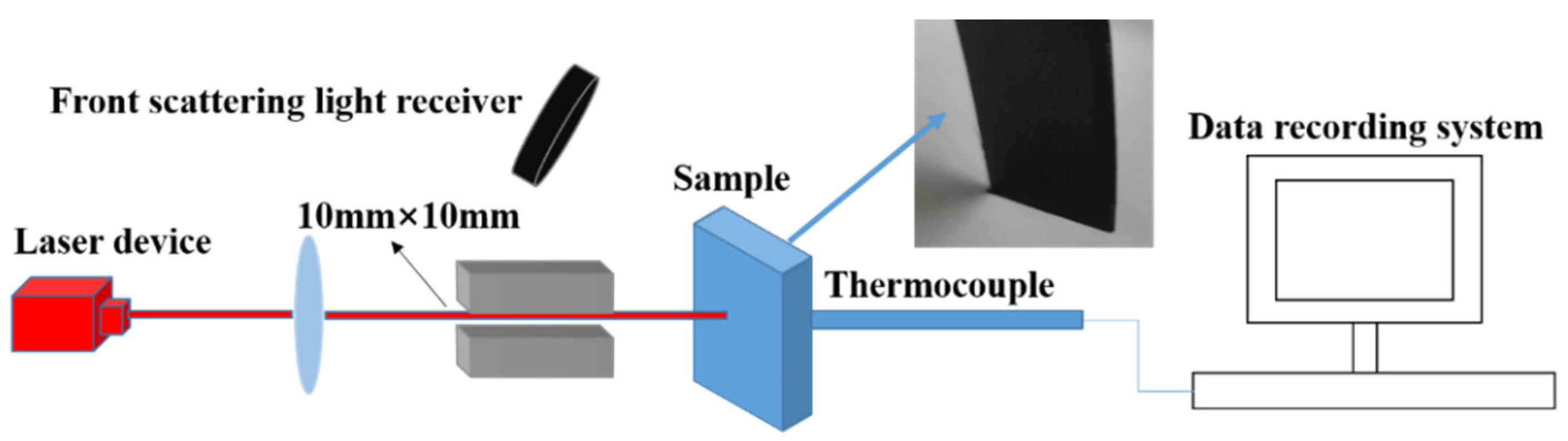
2. Materials and Methods

CFE composites (M40/4211) were provided by the material department of the China Academy of Space Technology. All materials are produced by itself. The resin type is 4211 resin, and the fiber is M40 carbon fiber with a density of 1.77 g/cm3. The laminates were made by a hot-pressing technology, which consists of two layers, and the fiber cloth is a two-way arrangement. The composites were cut into 40 mm × 40 mm pieces with a thickness of 0.4 mm and a mass of 1 g. Specimens were cleaned with distilled water and industrial alcohol to remove surface impurities before irradiation.
Laser irradiation has been a recognized characterization method for many years [8]. As shown in Figure 1, the laser irradiation experiment was performed using a continuous wave laser with a beam spot of 10 mm × 10 mm. The laser wavelength was 1070 nm, laser power density was 50–200 W/cm2, and irradiation time was 2–5 s. The back-surface temperature was measured using a thermocouple, the temperature difference between front surface and back surface can reach 500 °C during irradiation [12]. A scattering light receiver was used to record light reflected from the sample front surface; a data recording system was employed.
A scanning electron microscope (SEM) (BCPCA S4800: 15,000 V, 8600–9000 nA, working distance 15.6 mm) was used to observe the micro-morphologies of the composite, helpful in studying the laser damage behavior. An electronic balance was used to weigh the mass of the sample before and after irradiation, and the value is accurate to four decimal places. To reduce the errors, the mass was measured immediately after irradiation. The mass of the sample was weighed using an electronic balance before and after irradiation. The ablation rate (V) can be expressed by Equation (1):
V = Δm/t,
where the ratio of the mass change is Δm, and the irradiation time is t. The mass ablation rate was used to analyze the evolution of the composite ablation rate under different laser parameters.
The thermochemical reaction process of the composite was studied in an air atmosphere (Netzsch STA449 F3 thermal analyzer). The heating rate was 10 °C/s, and the temperature range was from room temperature to 900 °C. The chemical groups of the composites before and after irradiation were determined using Fourier transform infrared spectroscopy (FTIR, Nicolet 6700, Thermo fisher, Waltham, MA, USA).

3. Results and Discussion

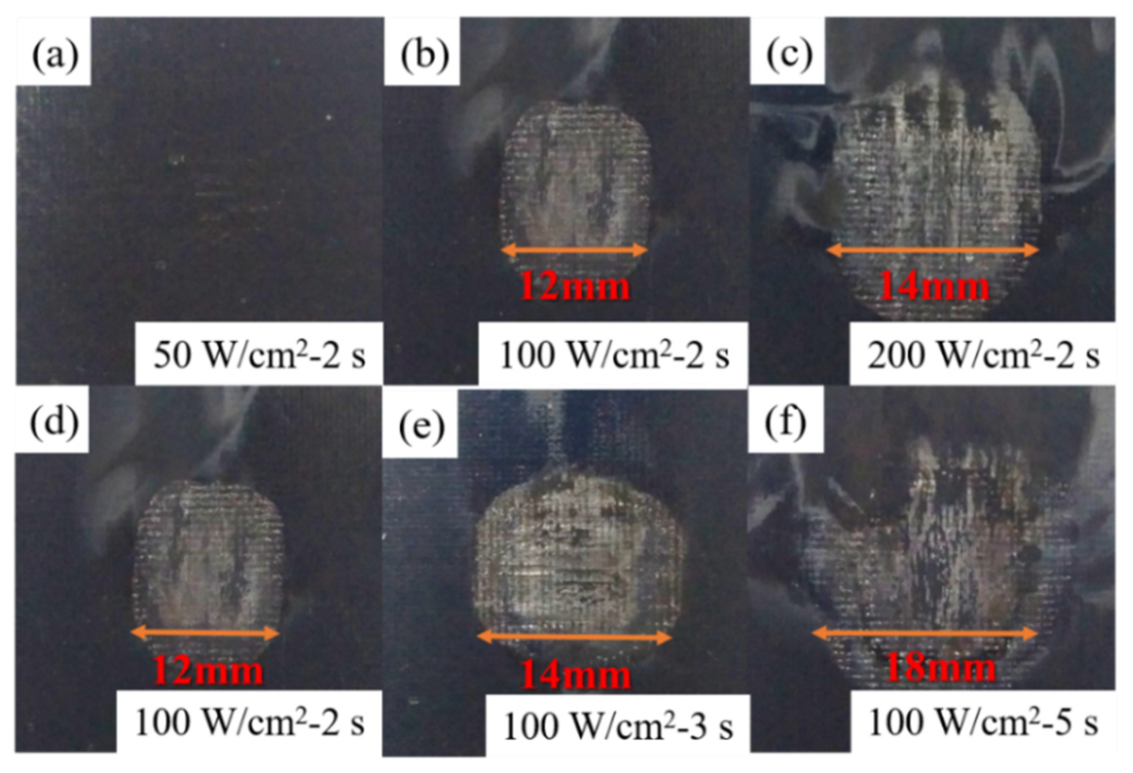
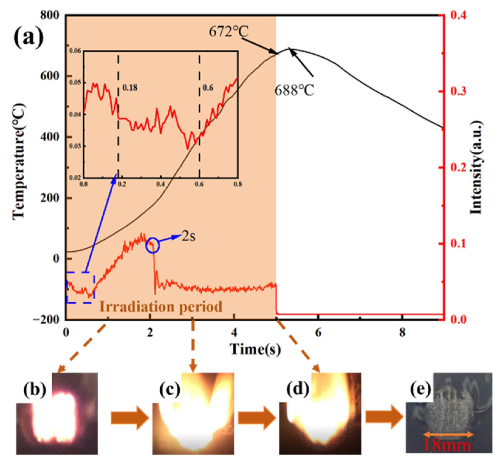
3.1. Macro-Morphologies and Ablation Behavior of the Composite

The macro-ablation behavior of CFE composites under different laser power densities and times is shown in Table 1. For an irradiation duration of 2 s, the ablation changes from slight smoke to flame as the power density is increased; at 200 W/cm2, a bright flame is produced, and the material burns violently. For a power density of 100 W/cm2, increasing the irradiation time from 2 to 5 s causes the flame to expand to the back surface of the composite, causing severe damage. For the same total energy, the increase in the power density has a greater influence than the irradiation time. Thermal diffusion under high power density is more rapid, causing higher temperature in a short time.
The macro-morphologies of the CFE composites after irradiation at various laser power densities are shown in Figure 2a–c. For the low level of 50 W/cm2, the surface of the composite exhibits no visible damage. At a higher power density (100 W/cm2), white smoke and an obvious flame are produced on the surface during irradiation. The irradiated area appears brighter because of the exposed carbon fiber. In comparison to the laser spot size (10 mm), the width of the ablation region is increased to 12 mm. At a higher power density (200 W/cm2), it is increased to 14 mm.
The macro-morphologies of the composites for different irradiation times are shown in Figure 2d–f. As irradiation time increases from 2 to 5 s, the width of the ablation region gradually increases from 12 to 18 mm; from these, it is deduced that the width of the ablation region increases by 2 mm/s. The ablation width increases with the increase in irradiation power and time. In addition, the relation between the ablation width L and the irradiation time t can be expressed by Equation (2). According to this relation, the width of the ablation region for different irradiation times from 2 to 5 s can be deduced. The heat generated by laser irradiation rapidly diffuses in the horizontal direction, leading to an increase in the width of the ablation region. The thermal conductivity of the composite determines the width of the ablation region to some extent. The thermal conductivity of the carbon fiber material varies greatly between the horizontal and vertical directions (i.e., along and perpendicular to the fibers); in the vertical fiber direction it is approximately 0.001–0.01 W/(m·K) at different temperatures; along the fiber direction (i.e., horizontal), it is approximately 50 times that in the vertical direction [35]. Meanwhile, the lower thermal conductivity in the vertical fiber direction blocks heat conduction, acting as a thermal barrier and protecting the composite.
L = 2t + 8, 2 ≤ t ≤ 5.

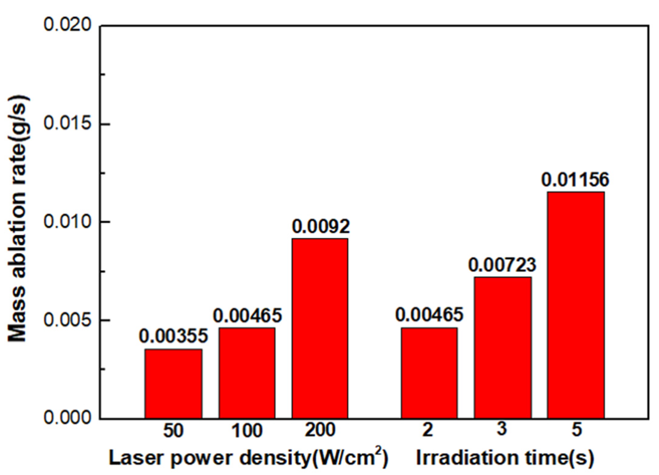
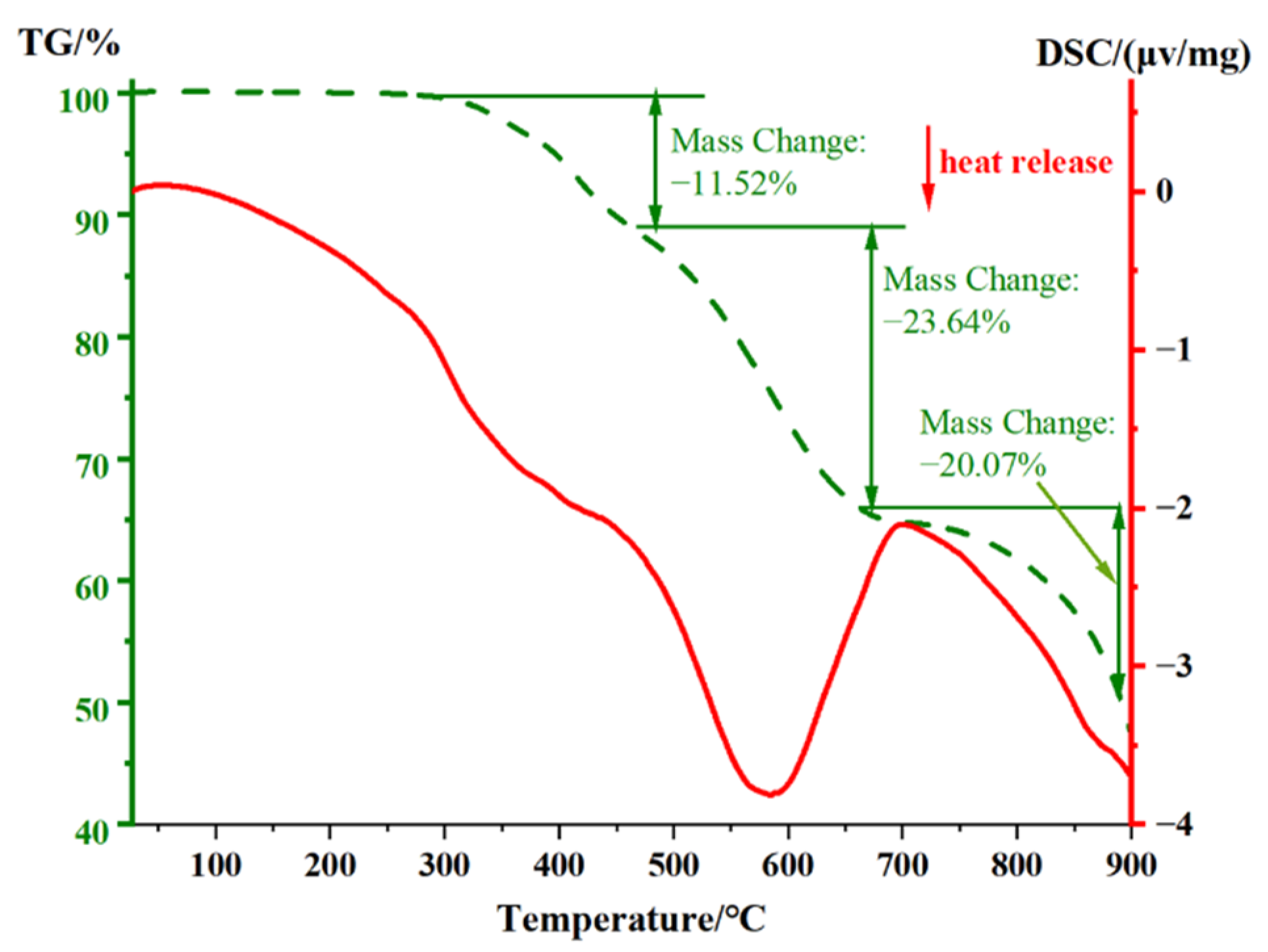
3.2. Mass Ablation Rate of the Composite

The mass ablation rates of CFE composites for an irradiation duration of 2 s and different laser power densities, and for a power of 100 W/cm2 but different durations, are shown in Figure 3. An increase in the power density or the irradiation time leads to more serious ablation damage. This behavior is characterized by an increase in the amount of material ablated and the degree of resin pyrolysis and product oxidation. It is also a factor that an expanded ablation region on the sample leads straightforwardly to an increase in the ablation rate. Notably, the ablation rate was stable in other studies [31,36]. However, the ablation rate in this study always shows an upward trend with an increase in the power density and irradiation time. According to the above analysis, more severe damage occurred in the laminar structure than in its bulk composite as a result of more severe damage in the thickness direction.

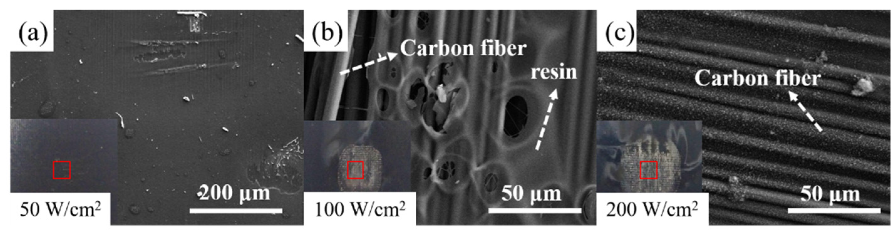
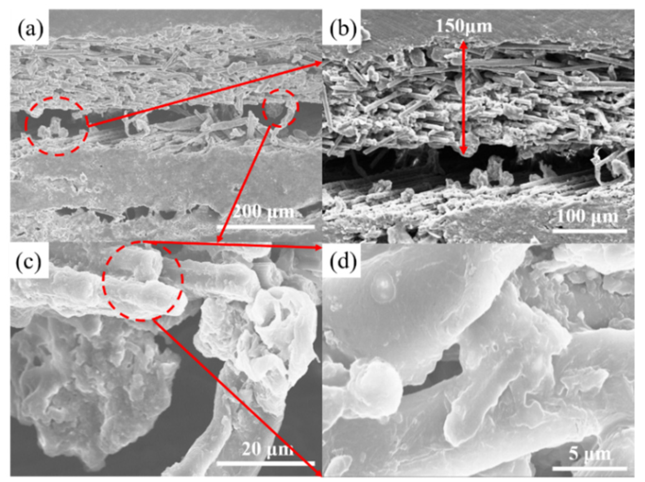
3.3. Micro-Morphologies of the Composites

The micro-morphologies of the composites are shown in Figure 4. When the laser power density is low (50 W/cm2), the micromorphology is unaffected. This is in good agreement with the macroscopic ablation behavior analysis. With an increase in the power density to 100 W/cm2, the carbon fibers are partially exposed, and only approximately one-third of the resin covering the surface remains. For a power density of 200 W/cm2, the carbon fibers in the irradiation region are almost completely exposed; however, the composite remains intact. There is no damage such as breaking of fibers caused by oxidation, the carbon fibers are not damaged under irradiation of 200 W/cm2 for 2 s, for which the damage threshold of carbon fiber was not reached. This is attributed to the fact that laser irradiation causes pyrolysis of the resin, and the gases produced take away a large amount of heat, reducing the temperature of the ablation region.
The micro-morphology of the irradiation region after exposure to 100 W/cm2 for 5 s is shown in Figure 5. As shown in Figure 5a, delamination of the layers occurs in the carbon fiber epoxy resin composite after laser irradiation. From the combination of internal thermal stress and gas expansion, separation of layers occurs inside the composite. Figure 5b shows that the separation occurs at a depth of 150 μm. The magnified image (Figure 5c) shows obvious clumps of resin adhering to the surface of the carbon fiber. However, these adhesions account for only a small amount of the resin, which indicates that much of it was lost inside the composite. The enlarged view in Figure 5d further indicates the presence of resin inside.

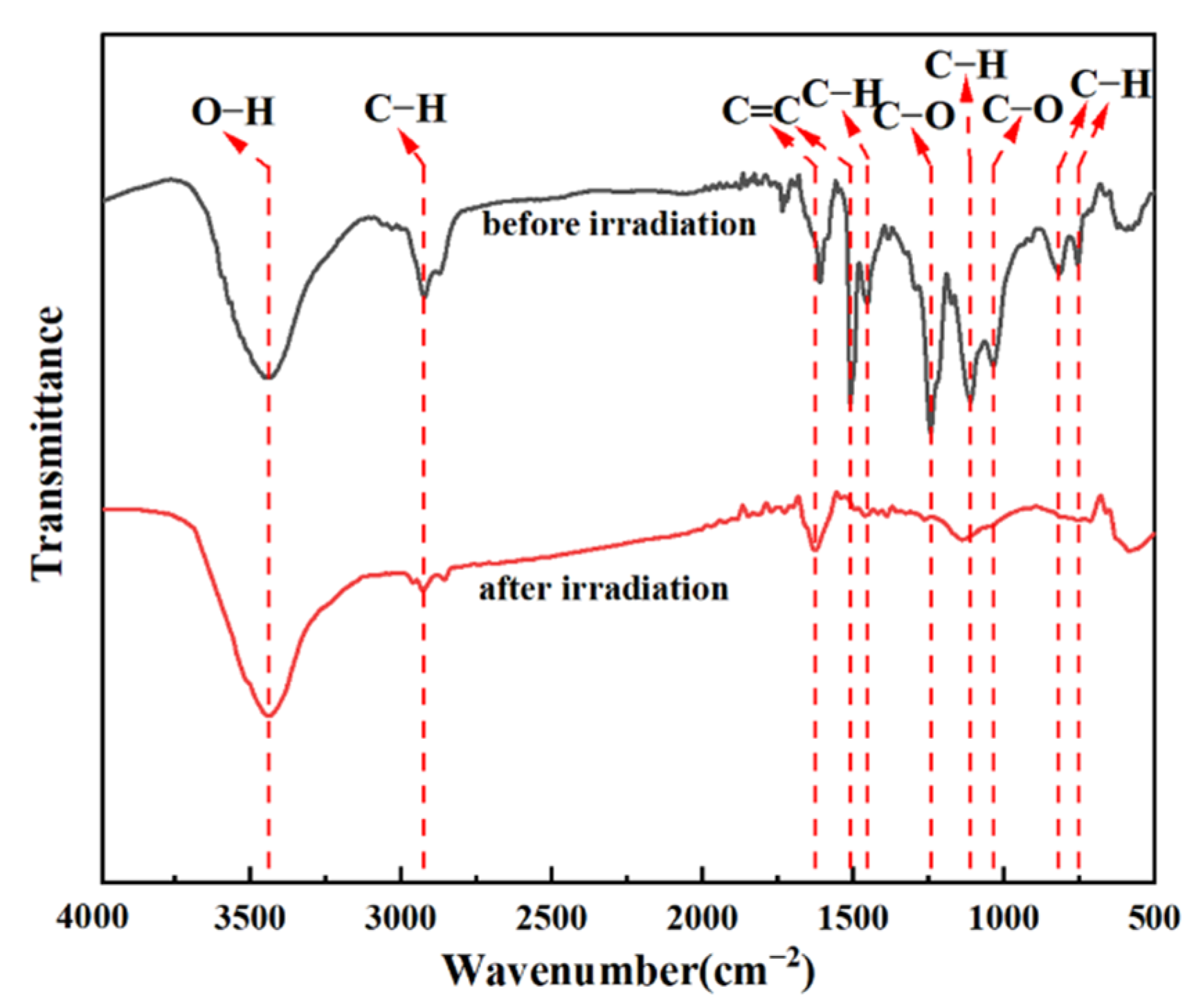
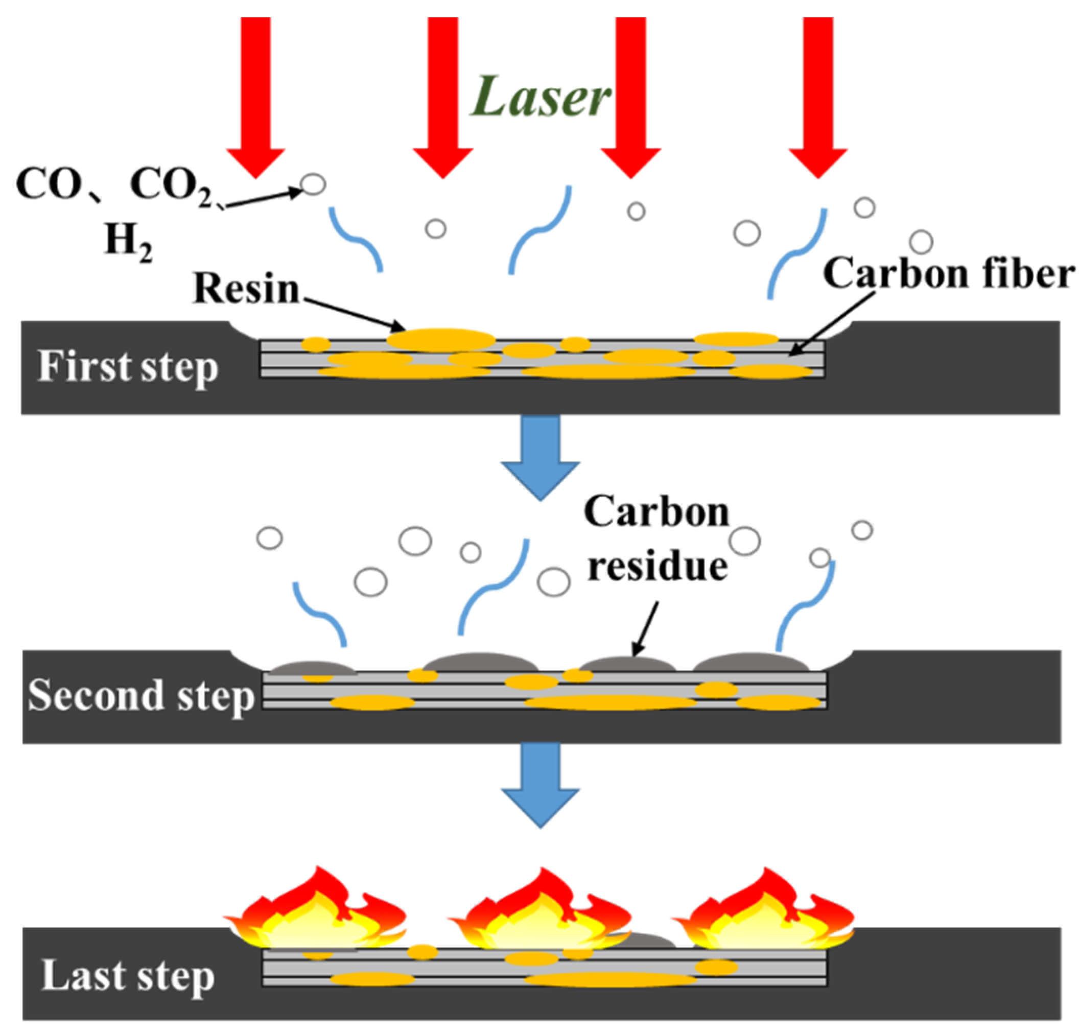
3.4. Damage Mechanism Analysis of the Composite

The damage mechanism is associated with the complicated interaction between the laser and material, which involves the physical response to light (including conventional optical factors), thermal and chemical factors. Therefore, light scattered from the surface, evolution of the temperature and thermogravimetric factors, and changes in composition were studied. The absorbed laser energy causes the temperature to rise rapidly since the composite cannot reflect or scatter all when it is irradiated by a high-energy laser. Figure 6a shows the real-time in situ measurement curve of the back-surface temperature and the front-surface scattered light of the composite irradiated by 100 W/cm2 for 5 s. The back-surface temperature rises rapidly from 22 °C to 672 °C within 5 s, and the heating rate gradually increases at an average rate of 130 °C/s. The back-surface temperature of 672 °C suggests that the front-surface temperature may reach over 1100 °C [12], much higher than 672 °C, which causes serious damage to the composite. Because of heat conduction, the temperature rises to 688 °C and then begins to drop, following a delay after irradiation.
The trace of front-surface scattered light begins to decrease at 0.18 s, then fluctuates slightly within a limited range. The curve begins to increase gradually at approximately 0.6 s, suddenly drops at 2 s, and then remains stable until the end of irradiation at 5 s. The composite was damaged at an irradiation power density of 100 W/cm2, and the pyrolysis of the surface resin mainly leads to damage to CFE composites. The front-surface scattered light has a sharp transformation at 0.18 s, which suggests that the surface morphology changes at this time. It can be inferred that resin pyrolysis begins after exposure to this level for a duration of 0.18 s, indicating that the composite has reached the damage threshold. The sample area is much larger than the laser spot, so the heat can carry out enough transverse thermal diffusion. However, if the sample area is smaller, the damage threshold reduces, which is caused by the transverse heat dissipation reduction. The rise of the scattered light at 0.6 s is caused by the combustion of the composite under irradiation (Figure 6b). As shown in Figure 6c, a bright flame appears on the surface during irradiation caused by the pyrolysis of the resin and the combustion of small-molecule products in the air; the resin releases combustible gases such as CO and H2 [36]. Black smoke can be produced when the composite is on fire, which has a weakening effect on the energy of laser [37]. After irradiation ends, a flame still exists on the surface (Figure 6d), which is in good agreement with the temperature analysis above. The flame gradually disappears and the composite surface shows an ablation morphology (Figure 6e).
To explore the response of CFE composites under a rising temperature profile, thermogravimetric analysis was conducted in air from 25 °C to 900 °C under a heating rate of 10 °C/s. The mass loss, heat absorption and release curves are shown in Figure 7. When the temperature is lower than 300 °C, the water adsorbed by the composite evaporates, resulting in a small weight loss. In the range 300–450 °C, the weight loss rate is 11.52%. This stage corresponds to the weight loss from epoxy resin pyrolysis. This indicates that when the temperature of the composite exceeds 300 °C, the composite is damaged, which is similar to the study of Chen [38]. This stage is accompanied by exothermic combustion of small-molecule pyrolysis products and hence there is no obvious endothermic peak for pyrolysis in this range. In the range of 450–700 °C, the weight loss rate is 23.64%, and an obvious heat release peak appears. The weight loss and heat release at this stage correspond to the oxidation of the residual carbon that is produced by epoxy resin pyrolysis. When the temperature is raised above 700 °C, the weight loss rate increases significantly. At 900 °C, the total weight loss of the composite is approximately 60%. This stage corresponds to the oxidation of the carbon fibers. According to Figure 6, the resin pyrolysis happens completely and the residual carbon begins to oxidize at this temperature, and the carbon fiber also oxidizes due to the higher surface temperature. With an increase in temperature, the carbon fiber epoxy resin composite gradually undergoes the above reaction. Notably, the thermogravimetric analysis heating rate is 10 °C/s, which is much lower than the real heating rate under laser irradiation. The composite reaches the latter reaction directly.
Since different molecular structures have different infrared absorption spectra (Figure 8), FTIR is used to analyze the compositional changes following laser irradiation. Before irradiation, the wide peak at 3440 cm−1 (the O-H bond stretching vibration) and the 2926 cm−1 peak (the C-H bond stretching vibration) are observed. The peaks at 1453 cm−1, 1112 cm−1, 819 cm−1, and 755 cm−1 correspond to C-H bond bending vibration. The peaks at 1510 cm−1 and 1626 cm−1 are C=C stretching vibrations in the aromatic ring, and the peaks at 1242 cm−1 and 1036 cm−1 correspond to C-O bond stretching vibrations in the aromatic ether. All of the above are normal FTIR peaks in the composite. After laser irradiation (100 W/cm2 for 5 s), resin pyrolysis produces small molecular products and gases, the result of breaking C-H and C-O bonds. In addition, the C=C bond is more resilient to the laser than C-H and C-O bonds. Hence, an increase in the number of C=C bonds is beneficial for improving the laser resistance of the composite.
Based on the above analysis, the response of the CFE composite under laser irradiation is shown in Figure 9, which is divided into three stages. In the first step, the laser is applied to the surface, leading to a high temperature. The surface resin pyrolysis generates carbon residues and small-molecule products, which generate CO, H2, and other gases under the action of oxygen. The lateral heat dissipation of the laser-induced local temperature rise leads to a larger affected area. In the second step, the temperature rise diffuses downward during the irradiation, increasing the pyrolysis of the internal resin, and the carbon residue is formed on the surface. Moreover, the carbon fiber is a dense body, and its oxidation rate is lower than that of carbon residue in the same environment. The results of the thermogravimetric analysis in the first stage correspond to the above steps. Finally, the CO, H2, and other combustible gases are generated to produce a flame, and the composite is eventually burned. The last stage corresponds to the second step of the thermogravimetric analysis and the irradiation after 0.6 s in Figure 8. The cracking and oxidation of composites are more serious, and the coupling effect of thermal and mechanical damage is caused inside. In contrast to pulsed lasers, continuous irradiation affects the depth of the effects more strongly.

4. Conclusions

In the previous studies, there were few researches on laminar structures irradiated by continuous-wave lasers. In this work, the laser irradiation behavior of CFE composites with a laminar structure was studied under the 1070 nm wavelength laser, and especially the damage threshold was determined. The width of the ablation region and the ablation rate increase gradually with an increase in laser power density and irradiation duration, and the ablation rate can reach 0.01156 g/s when irradiated at 100 W/cm2 for 5 s. The composite was not damaged at 50 W/cm2-2 s. According to the front-surface scattered light curve, the resin begins to pyrolyze after an irradiation duration of 0.18 s under 100 W/cm2 when it reaches the damage threshold. With the combined effect of internal thermal stress and gas expansion, separation of layers occurs inside the composite, an effect different from that in bulk composites. In addition, the damage mechanism is understood by the temperature evolution data, thermogravimetric analysis, and composition change studies. Therefore, this work has important reference for the safe and stable use of laminar CFE composites, and improves the understanding of laser interaction with matter.

Author Contributions

Conceptualization, Y.Y. and A.A.R.; methodology, H.L.; formal analysis, Y.Y.; resources, H.G.; data curation, W.T., X.L. and Z.Z.; writing—original draft preparation, Y.Y.; writing—review and editing, L.G. and X.T.; visualization, Y.Y.; supervision, Z.M.; project administration, Z.M. All authors have read and agreed to the published version of the manuscript.

Funding

This research was funded by the National Natural Science Foundation of China (No. 52073029) and China National Key Laboratory Foundation of Science and Technology on Materials under Shock and Impact (No. 6142902200301).

Conflicts of Interest

The authors declare no conflict of interest. The funders had no role in the design of the study; in the collection, analyses, or interpretation of data; in the writing of the manuscript, or in the decision to publish the results.

References

  1. Ecault, R.; Boustie, M.; Touchard, F.; Pons, F.; Berthe, L.; Chocinski-Arnault, L.; Ehrhart, B.; Bockenheimer, C. A Study of Composite Material Damage Induced by Laser Shock Waves. Compos. Part A Appl. Sci. Manuf. 2013, 53, 54–64. [Google Scholar] [CrossRef] [Green Version]
  2. Bi-liu, L.I.U.; Jia-ming, S.H.I.; Xue-cheng, Y.A.N.; Zhi-dan, L.I.N.; Yan-liang, X.U.; Li, C. Laser Threat and Its Protection for the Satellite. Infrared Laser Eng. 2009, 38, 470–475. [Google Scholar]
  3. Li, W.; Ma, Z.; Gao, L.; Wang, F.; Wang, L.; Wei, C. Investigation on Laser Ablation Properties of CaCO3 Coating. Mater. China 2017, 36, 126–131. [Google Scholar] [CrossRef]
  4. Gallais, L.; Commandré, M. Laser-Induced Damage Thresholds of Bulk and Coating Optical Materials at 1030 Nm, 500 Fs. Appl. Opt. 2014, 53, A186. [Google Scholar] [CrossRef] [PubMed]
  5. Chen, G.; Zhu, S.; Jiang, Z.; Gao, L.; Ma, Z.; Liu, L. Laser Ablation Protection of Polymer Matrix Composites by Adhesive Inorganic Coatings. J. Mater. Sci. 2017, 52, 12734–12741. [Google Scholar] [CrossRef]
  6. Momozawa, A.; Yokote, N.; Terutsuki, D.; Komurasaki, K. Dynamic Oxidation of SiC with Arc-Heated Plasma Wind Tunnel and Laser Heating. Vacuum 2021, 185, 109899. [Google Scholar] [CrossRef]
  7. Cheng, S.; Geng, L.; Liu, X.; Wang, Y. Laser Ablation Behavior and Mechanism of C/SiC Coated with ZrB2 –MoSi2–SiC/Mo Prepared by HVOF. Ceram. Int. 2020, 46, 17752–17762. [Google Scholar] [CrossRef]
  8. Ma, C.; Ma, Z.; Gao, L.; Wu, T.; Wang, F.; Ishida, H. Toward Improving the Reflectivity of Ablative Heat-Insulating Coating under High-Energy Laser Irradiation. J. Mater. Sci. 2020, 55, 15787–15796. [Google Scholar] [CrossRef]
  9. Zhu, J.; Ma, Z.; Gao, L.; Liu, Y.; Wang, F. Influence of Microstructure on the Optical Property of Plasma-Sprayed Al, Cu, and Ag Coatings. Mater. Des. 2016, 111, 192–197. [Google Scholar] [CrossRef]
  10. Luan, X.; Yuan, J.; Wang, J.; Tian, M.; Cheng, L.; Ionescu, E.; Riedel, R. Laser Ablation Behavior of Cf/SiHfBCN Ceramic Matrix Composites. J. Eur. Ceram. Soc. 2016, 36, 3761–3768. [Google Scholar] [CrossRef]
  11. Liu, T.; Niu, Y.; Pan, X.; Shi, M.; Zheng, X.; Yu, J.; Ding, C. Laser Ablation Behaviors of Vacuum Plasma Sprayed ZrC-Based Coatings. J. Am. Ceram. Soc. 2019, 102, 4247–4258. [Google Scholar] [CrossRef]
  12. Herr, N.C.; Gonzales, A.E.; Perram, G.P. Kinetics, Evolving Thermal Properties, and Surface Ignition of Carbon Fiber Reinforced Epoxy Composite during Laser-Induced Decomposition. Polym. Degrad. Stab. 2018, 152, 147–161. [Google Scholar] [CrossRef]
  13. Ling, X.; Wang, G.; Zhao, Y.; Shao, J.; Fan, Z. Laser-Induced Damage of the Optical Films Prepared by Electron Beam Evaporation and Ion Beam Sputtering in Vacuum. Optik 2014, 125, 6474–6477. [Google Scholar] [CrossRef]
  14. Tianyu, Z.; Bin, K.; Minsun, C.; Jun, Y.; Houman, J. Anti-Laser Performance Test of Aluminum Alloy Plates Reinforced by Ceramic Coating. Infrared Laser Eng. 2017, 46, 606002–606006. [Google Scholar] [CrossRef]
  15. Xiulan, L.; Gao, W.; Xiaofeng, L. Investigation of the Intrinsic Damage Mechanisms for Optical Thin Film in Vacuum Environments. Laser Optoelectron. Prog. 2015, 52, 53101–53106. [Google Scholar]
  16. Jiang, Y.P.; Wu, J. Enhancement of Interface Strength of Carbon Fiber/Epoxy Resin Composites Filled with Low-Dimensional Materials. Compos. Interfaces 2021, 28, 273–286. [Google Scholar] [CrossRef]
  17. Chai, G.; Zhu, G.; Gao, Y.; Zhou, J.; Gao, S. Flame Retardancy of Carbon Nanotubes Reinforced Carbon Fiber/Epoxy Resin Composites. Appl. Sci. 2019, 9, 3275. [Google Scholar] [CrossRef] [Green Version]
  18. Jiang, J.; Deng, G.; Chen, X.; Gao, X.; Guo, Q.; Xu, C.; Zhou, L. On the Successful Chemical Recycling of Carbon Fiber/Epoxy Resin Composites under the Mild Condition. Compos. Sci. Technol. 2017, 151, 243–251. [Google Scholar] [CrossRef]
  19. Phonthammachai, N.; Li, X.; Wong, S.; Chia, H.; Tjiu, W.W.; He, C. Fabrication of CFRP from High Performance Clay/Epoxy Nanocomposite: Preparation Conditions, Thermal–Mechanical Properties and Interlaminar Fracture Characteristics. Compos. Part A Appl. Sci. Manuf. 2011, 42, 881–887. [Google Scholar] [CrossRef]
  20. Del Real, J.C.; Ballesteros, Y.; Chamochin, R.; Abenojar, J.; Molisani, L. Influence of Surface Preparation on the Fracture Behavior of Acrylic Adhesive/CFRP Composite Joints. J. Adhes. 2011, 87, 366–381. [Google Scholar] [CrossRef]
  21. Li, Y.; Zhang, H.; Liu, Y.; Wang, H.; Huang, Z.; Peijs, T.; Bilotti, E. Synergistic Effects of Spray-Coated Hybrid Carbon Nanoparticles for Enhanced Electrical and Thermal Surface Conductivity of CFRP Laminates. Compos. Part A Appl. Sci. Manuf. 2018, 105, 9–18. [Google Scholar] [CrossRef]
  22. Hopmann, C.; Karatzias, C.; Wagner, R.; Boettcher, A.; Fischer, K. Production of CFRP components with clear surface layer in the PU spray impregnation process. AIP Conf. Proc. 2017, 1914, 100001. [Google Scholar]
  23. Medvids, A.; Onufrijevs, P.; Kaupužs, J.; Eglitis, R.; Padgurskas, J.; Zunda, A.; Mimura, H.; Skadins, I.; Varnagiris, S. Anatase or Rutile TiO2 Nanolayer Formation on Ti Substrates by Laser Radiation: Mechanical, Photocatalytic and Antibacterial Properties. Opt. Laser Technol. 2021, 138, 106898. [Google Scholar] [CrossRef]
  24. Li, F.; Liu, Y.; Qu, C.B.; Xiao, H.M.; Hua, Y.; Sui, G.X.; Fu, S.Y. Enhanced Mechanical Properties of Short Carbon Fiber Reinforced Polyethersulfone Composites by Graphene Oxide Coating. Polymer 2015, 59, 155–165. [Google Scholar] [CrossRef]
  25. Wang, R.; Jiang, L.; Liu, W.; Lv, X. Study on Hygrothermal Properties of Carbon Fiber Reinforced Composites Aged in Cyclic Environment. Polym. Polym. Compos. 2011, 19, 313–317. [Google Scholar] [CrossRef]
  26. Wu, W. Influence of interfacial property on failure mode of unilateralism carbon fiber reinforced resin matrix composite subject to short-beam shear. In Advanced Materials Research; Trans Tech Publications Ltd.: Bäch, Switzerland, 2012. [Google Scholar]
  27. Dong, C.; Zhou, J.; Ji, X.; Yin, Y.; Shen, X. Study of the Curing Process of Carbon Fiber Reinforced Resin Matrix Composites in Autoclave Processing. Procedia Manuf. 2019, 37, 450–458. [Google Scholar] [CrossRef]
  28. Khalil, Y.F. Eco-Efficient Lightweight Carbon-Fiber Reinforced Polymer for Environmentally Greener Commercial Aviation Industry. Sustain. Prod. Consum. 2017, 12, 16–26. [Google Scholar] [CrossRef]
  29. Xu, L.; Lu, J.; Li, K.; Hu, J. Study on the Mechanism of Inhomogeneous Microdamage in Short-Pulse Laser Processing of Carbon Fiber Reinforced Plastic. J. Reinf. Plast. Compos. 2021, 40, 568–576. [Google Scholar] [CrossRef]
  30. Schmidt, B.; Rose, M.; Zimmermann, M.; Kaestner, M. Analysis of Process-Induced Damage in Remote Laser Cut Carbon Fibre Reinforced Polymers. J. Mater. Process. Technol. 2021, 295, 117162. [Google Scholar] [CrossRef]
  31. Minsun, C.; Houman, J.; Tianyu, Z.; Xiangyu, Z. Study on the Laser Irradiation Effects on Coating Reinforced Glass Fiber/Resin Composite Material. High-Power Lasers Technol. Syst. 2016, 9990, 55–62. [Google Scholar]
  32. Yongqiang, Z.; Li, Z.; Yanhui, T. Damage Characterization of Carbon Fiber/Epoxy Composite under Laser Irradiation and Tangential Flow. High Power Laser Part Beams 2015, 27, 71014–71015. [Google Scholar] [CrossRef]
  33. Xinlong, C.; Zhengliang, L.; Bo, H.; Kuan, H. Analysis of Carbon/Epoxy Laminates Ablation Subject to Laser Irradiation. Infrared Laser Eng. 2011, 40, 1691–1695. [Google Scholar]
  34. Shanshan, J.; Jixing, C.; Guangyong, J.; Boshi, Y. Research of Damage Morphology of Carbon Fiber Epoxy Resin Irradiated by Millisecond/Nanosecond Pulsed Laser. Laser Technol. 2018, 42, 775–779. [Google Scholar]
  35. Zhang, H.; Wu, K.; Xiao, G.; Du, Y.; Tang, G. Experimental Study of the Anisotropic Thermal Conductivity of 2D Carbon-Fiber/Epoxy Woven Composites. Compos. Struct. 2021, 267, 113870. [Google Scholar] [CrossRef]
  36. Ma, C.; Ma, Z.; Gao, L.; Liu, Y.; Wu, T.; Wang, F.; Ishida, H. Ablation Behavior of Boron-Modified Phenolic Resin Irradiated by High-Energy Continuous-Wave Laser and Its Evolution of Carbon Structure. Mater. Des. 2019, 180, 119–157. [Google Scholar] [CrossRef]
  37. He, M.; Zhiliang, M.; Linzhu, C.; Xinwei, L.; Menglian, Z. Experimental Investigation on Thermal Ablation of Carbon-Fiber/Epoxy Composite Irradiated by Continuous Wave Laser. In Third International Symposium on Laser Interaction with Matter; SPIE: Bellingham, WA, USA, 2015; Volume 9543. [Google Scholar]
  38. Bo, C.; Hong, W.A.N.; Jingyang, M.U.; Shuxin, B.A.I. Ablative Mechanism of Carbon-Fiber/Epoxy Composite Irradiated by Repetition Frequency Laser. High Power Laser Part. Beams 2008, 20, 547–552. [Google Scholar]
Figure 1. Schematic diagram of laser irradiation platform.
Crystals 12 01767 g001
Figure 2. Macro-morphologies of CFE composites irradiated with different power densities and irradiation times: (a) irradiated at 50 W/cm2-2 s; (b) irradiated at 100 W/cm2-2 s; (c) irradiated at 200 W/cm2-2 s; (d) irradiated at 100 W/cm2-2 s; (e) irradiated at 100 W/cm2-3 s; (f) irradiated at 100 W/cm2-5 s.
Crystals 12 01767 g002
Figure 3. Ablation rates of different power densities and irradiation times.
Crystals 12 01767 g003
Figure 4. Micro-morphologies of the CFE composites with different power densities irradiated for 2 s: (a) irradiated at 50 W/cm2; (b) irradiated at 100 W/cm2; (c) irradiated at 200 W/cm2.
Crystals 12 01767 g004
Figure 5. Cross-section morphologies of the CFE composite irradiated at 100 W/cm2 for 5 s: (a) typical section morphology; (b) magnified morphology of crack; (c) morphology of carbon fiber; (d) high-magnification image.
Crystals 12 01767 g005
Figure 6. Laser irradiation behavior of CFE composite irradiated at 100 W/cm2 for 5 s: (a) the back-surface temperature of the composite and the front-surface scattered light curve; (b) the morphology at 0.6 s; (c) the morphology at 4 s; (d) the morphology at 5 s; (e) the morphology after irradiation.
Crystals 12 01767 g006
Figure 7. Thermal analysis of CFE composites under air atmosphere.
Crystals 12 01767 g007
Figure 8. FTIR spectra of CFE composite before and after laser irradiation.
Crystals 12 01767 g008
Figure 9. Schematic diagram of CFE composite response under laser irradiation.
Crystals 12 01767 g009
Table 1. Macro-ablation behavior of CFE composites under different irradiation conditions.
Power Density/(W·cm−2)Irradiation Time/sAblation BehaviorAblation Morphology
502Slight smokeCrystals 12 01767 i001
505Slight red burnCrystals 12 01767 i002
1002FlameCrystals 12 01767 i003
1003Back-surface flameCrystals 12 01767 i004
1005Back-surface flameCrystals 12 01767 i005
2002Violent burnCrystals 12 01767 i006
Publisher’s Note: MDPI stays neutral with regard to jurisdictional claims in published maps and institutional affiliations.

