

First-Principle Investigation of Hypothetical NiF4 Crystal Structures

Abstract
:1. Introduction
2. Computational Details
3. Results and Discussion
3.1. General Comparison among the Different NiF4 Polymorphs
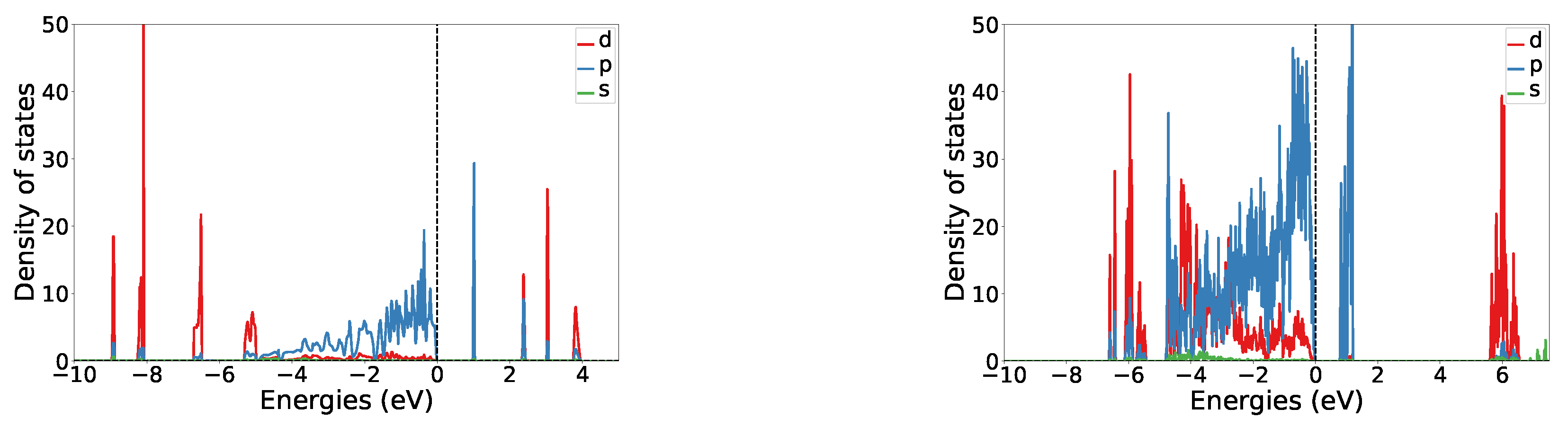
3.2. Structure I
3.3. Structure V
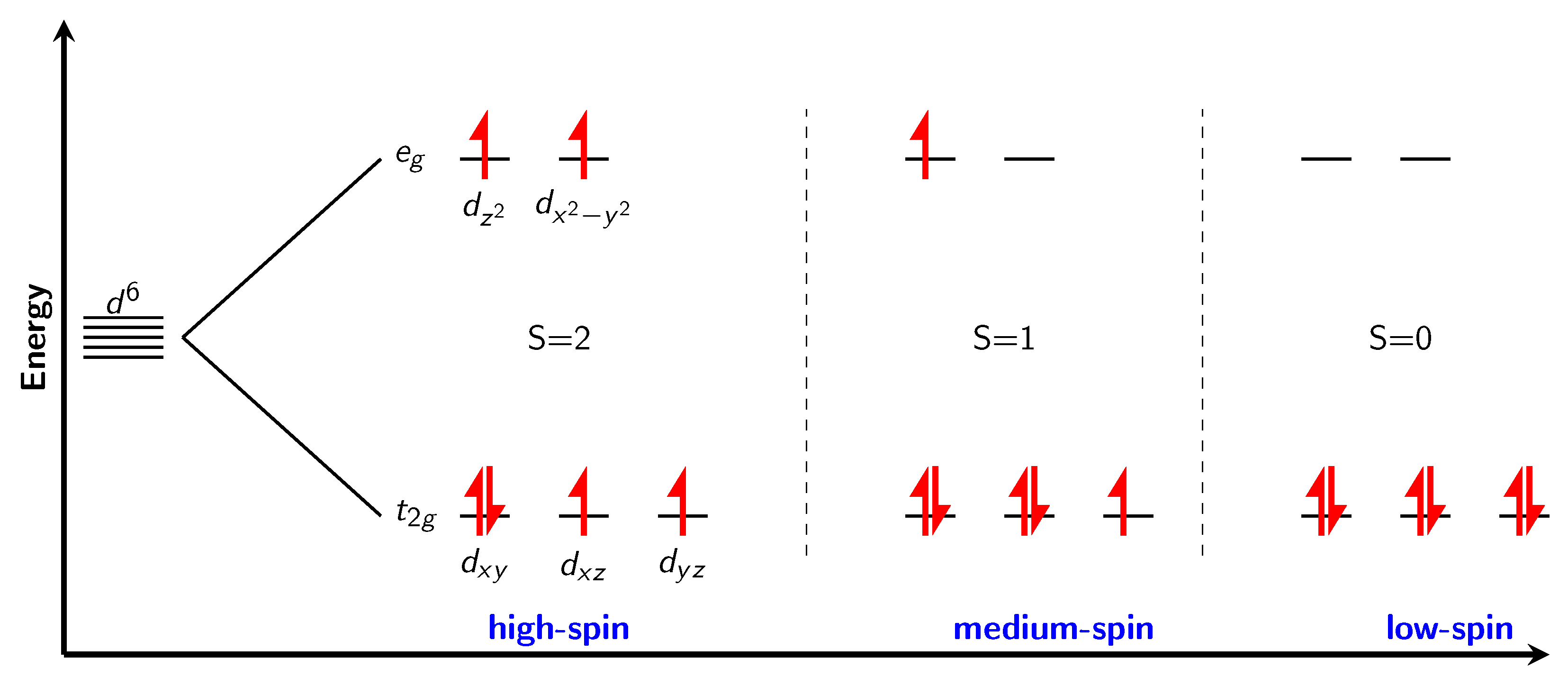
3.4. Magnetism
4. Conclusions
Author Contributions
Funding
Data Availability Statement
Acknowledgments
Conflicts of Interest
References
- Lemal, D.M. Perspective on fluorocarbon chemistry. J. Org. Chem. 2004, 69, 1–11. [Google Scholar] [CrossRef] [PubMed]
- Anilkumar, D.; Sudarshan, P.; Ragavan, K.; Babu, M.N. A review of artificial blood. Int. J. Pharm. Chem. Biol. Sci. 2015, 5, 477–480. [Google Scholar]
- Inoue, M.; Sumii, Y.; Shibata, N. Contribution of organofluorine compounds to pharmaceuticals. ACS Omega 2020, 5, 10633–10640. [Google Scholar] [CrossRef] [PubMed]
- Simons, J.H.; Harland, W.J. Production of Fluorocarbons. J. Electrochem. Soc. 1949, 95, 55. [Google Scholar] [CrossRef]
- Simons, J.H. Electrochemical Process of Making Fluorine-Containing Carbon Compounds. U.S. Patent 2,519,983, 22 August 1950. [Google Scholar]
- Ignat’ev, N.V. Electrochemical Fluorination: A Powerful Tool for the Preparation of Organofluorine Compounds. In Modern Synthesis Processes and Reactivity of Fluorinated Compounds, Progress in Fluorine Science; Elsevier Inc.: Amsterdam, The Netherlands, 2017; pp. 71–123. [Google Scholar]
- Sartori, P.; Ignat’ev, N. The actual state of our knowledge about mechanism of electrochemical fluorination in anhydrous hydrogen fluoride (Simons process). J. Fluor. Chem. 1998, 87, 157–162. [Google Scholar] [CrossRef]
- Costa, M.M.R.; Paixão, J.A.; De Almeida, M.J.M.; Andrade, L.C.R. Charge densities of two rutile structures: NiF2 and CoF2. Acta Crystallogr. Sect. B Struct. Sci. 1993, 49, 591–599. [Google Scholar] [CrossRef] [Green Version]
- Mattsson, S.; Senges, G.; Riedel, S.; Paulus, B. Combining theory and experiment to characterize the voltammetric behavior of nickel anodes in the Simons process. Chem.—A Eur. J. 2020, 26, 10781–10786. [Google Scholar] [CrossRef]
- Zemva, B.; Lutar, K.; Chacon, L.; Fele-Beuermann, M.; Allman, J.; Shen, C.; Bartlett, N. Thermodynamically unstable fluorides of nickel: NiF4 and NiF3 syntheses and some properties. J. Am. Chem. Soc. 1995, 117, 10025–10034. [Google Scholar] [CrossRef]
- Mattsson, S.; Paulus, B. Density Functional Theory Calculations of Structural, Electronic, and Magnetic Properties of the 3d Metal Trifluorides MF3 (M= Ti-Ni) in the Solid State. J. Comput. Chem. 2019, 40, 1190–1197. [Google Scholar] [CrossRef]
- Tramšek, M.; Žemva, B. Higher fluorides of nickel: Syntheses and some properties of Ni2F5. Acta Chim. Slov. 2002, 49, 209–220. [Google Scholar]
- Lindič, T.; Sinha, S.; Mattsson, S.; Paulus, B. Prediction of a model crystal structure for Ni2F5 by first-principles calculations. Z. für Naturforsch. B 2022, 77, 469–473. [Google Scholar] [CrossRef]
- Li, L.; Sakr, A.K.; Schlöder, T.; Klein, S.; Beckers, H.; Kitsaras, M.; Snelling, H.V.; Young, N.A.; Andrae, D.; Riedel, S. Searching for Monomeric Nickel Tetrafluoride: Unravelling Infrared Matrix Isolation Spectra of Higher Nickel Fluorides. Angew. Chem. 2021, 133, 6461–6464. [Google Scholar] [CrossRef]
- Casteel, W.J.; Lohmann, D.H.; Bartlett, N. Room temperature preparations of second and third transition series tetrafluorides and a possible novel structure type for OsF4 and RhF4. J. Fluor. Chem. 2001, 112, 165–171. [Google Scholar] [CrossRef]
- Wright, A.F.; Fender, B.E.F.; Bartlett, N.; Leary, K. A neutron powder diffraction study of palladium tetrafluoride. Inorg. Chem. 1978, 17, 748–749. [Google Scholar] [CrossRef]
- Hoppe, R.; Dähne, W. Die Kristalistruktur von SnF4 und PbF4. Naturwissenschaften 1962, 49, 254–255. [Google Scholar] [CrossRef]
- Papiernik, R.; Mercurio, D.; Frit, B. Structure du tétrafluorure de zirconium, ZrF4α. Acta Crystallogr. Sect. B Struct. Crystallogr. Cryst. Chem. 1982, 38, 2347–2353. [Google Scholar] [CrossRef]
- Casteel, W.J., Jr.; Wilkinson, A.P.; Borrmann, H.; Serfass, R.E.; Bartlett, N. Preparation and structure of ruthenium tetrafluoride and a structural comparison with ruthenium trifluoride and ruthenium pentafluoride. Inorg. Chem. 1992, 31, 3124–3131. [Google Scholar] [CrossRef]
- Krämer, O.; Müller, B.G. Zur Struktur des Chromtetrafluorids. Z. für Anorg. und Allg. Chem. 1995, 621, 1969–1972. [Google Scholar] [CrossRef]
- Kresse, G.; Hafner, J. Ab initio molecular dynamics for liquid metals. Phys. Rev. B 1993, 47, 558–561. [Google Scholar] [CrossRef]
- Kresse, G.; Hafner, J. Ab initio molecular-dynamics simulation of the liquid-metal–amorphous-semiconductor transition in germanium. Phys. Rev. B 1994, 49, 14251–14269. [Google Scholar] [CrossRef]
- Kresse, G.; Furthmüller, J. Efficiency of ab initio total energy calculations for metals and semiconductors using a plane-wave basis set. Comput. Mater. Sci. 1996, 6, 15–50. [Google Scholar] [CrossRef]
- Blöchl, P.E. Projector augmented-wave method. Phys. Rev. B 1994, 50, 17953–17979. [Google Scholar] [CrossRef] [PubMed]
- Kresse, G.; Joubert, D. From ultrasoft pseudopotentials to the projector augmented-wave method. Phys. Rev. B 1999, 59, 1758–1775. [Google Scholar] [CrossRef]
- Perdew, J.P.; Burke, K.; Ernzerhof, M. Generalized gradient approximation made simple. Phys. Rev. Lett. 1996, 77, 3865. [Google Scholar] [CrossRef] [PubMed] [Green Version]
- Dudarev, S.L.; Botton, G.A.; Savrasov, S.Y.; Humphreys, C.J.; Sutton, A.P. Electron-energy-loss spectra and the structural stability of nickel oxide: An LSDA+ U study. Phys. Rev. B 1998, 57, 1505. [Google Scholar] [CrossRef]
- Tang, W.; Sanville, E.; Henkelman, G. A grid-based Bader analysis algorithm without lattice bias. J. Phys. Condens. Matter 2009, 21, 084204. [Google Scholar] [CrossRef]
- Momma, K.; Izumi, F. VESTA3 for three-dimensional visualization of crystal, volumetric and morphology data. J. Appl. Crystallogr. 2011, 44, 1272–1276. [Google Scholar] [CrossRef]
- Senges, G.; Buzanich, A.G.; Lindic, T.; Gully, T.A.; Winter, M.; Radtke, M.; Reinholz, U.; Roder, B.; Steinhauer, S.; Paulus, B.; et al. Unravelling the nature of the anodic black film Formed During the SImons Process by an In-Situ X-Ray Absorption Near Edge Structure Investigation. Angew. Chem. 2022, submitted.


| Parent Structure | Cut-Off Energy | K-Point Mesh | Smearing Width |
|---|---|---|---|
| PdF4 | 750 | 6 × 6 × 6 | 0.01 |
| SnF4 | 850 | 12 × 12 × 6 | 0.01 |
| ZrF4 | 850 | 4 × 4 × 4 | 0.01 |
| OsF4 | 850 | 4 × 4 × 8 | 0.03 |
| RuF4 | 750 | 4 × 4 × 4 | 0.05 |
| CrF4 | 850 | 6 × 6 × 12 | 0.02 |
| Structure | Parent Structure (CN) | Energy | Magnetic Order | BD(av.) | BG | |
|---|---|---|---|---|---|---|
| I | RuF4 (6) | 0.000 | 2.18 | AF | 1.876 | 0.98 |
| II | PdF4 (6) | +0.1605 | 2.16 | AF | 1.891 | 0.87 |
| III | OsF4 (6) | +0.1836 | 2.17 | AF | 1.891 | 0.83 |
| IV | CrF4 (6) | +0.4954 | 1.79 | AF | 1.844 | 0.00 |
| V | ZrF4 (8) | +0.5236 | 2.02 | AF | 2.031 | 0.84 |
| VI | SnF4 (6) | +0.7968 | 1.90 | AF | 1.812 | 0.52 |
| NiF2 [9] | NiF3 [11] | Ni2F5 [13] | NiII[NiIVF6] [30] | NiF4 | |
|---|---|---|---|---|---|
| OS (Ni) | +2 | +3 | +2/+3 | +2/+4 | +4 |
| Energy | 0 | +0.2302 | +0.3297 | +0.5674 | +1.0091 |
| 2.83 | 2.49 | 2.56 | 2.48 | 2.18 | |
| BD(av.) | 2.021 | 1.883 | 2.085/1.874 | 1.984/1.829 | 1.876 |
| Structure I | Structure V | ||
|---|---|---|---|
| # F | Distance | # F | Distance |
| 1 (n) | 1.860 | 1 | 2.107 |
| 2 (b) | 1.933 | 2 | 1.986 |
| 3 (b) | 1.836 | 3 | 1.980 |
| 4 (b) | 1.933 | 4 | 1.988 |
| 5 (b) | 1.836 | 5 | 2.133 |
| 6 (n) | 1.860 | 6 | 1.990 |
| Structure | Quantity | Ni | F (Non-Bridging) | F (Bridging) |
|---|---|---|---|---|
| I | 2.4 | 0.6 | 0.0 | |
| qB | +1.8 | −0.3 | −0.6 | |
| II | 2.3 | 0.6 | 0.0 | |
| qB | +1.7 | −0.3 | −0.6 | |
| III | 2.4 | 0.6 | 0.2 | |
| qB | +1.7 | −0.3 | −0.6 | |
| IV | 2.4 | 0.5 | 0.2 | |
| qB | +1.6 | −0.3 | −0.6 | |
| V | 1.9 | 0.8 & 0.4 | 0.2 | |
| qB | +1.5 | 0.0 & −0.4 | −0.5 | |
| VI | 2.7 | 0.5 | 0.2 | |
| qB | +1.9 | −0.3 | −0.6 |
Publisher’s Note: MDPI stays neutral with regard to jurisdictional claims in published maps and institutional affiliations. |
© 2022 by the authors. Licensee MDPI, Basel, Switzerland. This article is an open access article distributed under the terms and conditions of the Creative Commons Attribution (CC BY) license (https://creativecommons.org/licenses/by/4.0/).
Share and Cite
Lindič, T.; Schulz, A.; Paulus, B. First-Principle Investigation of Hypothetical NiF4 Crystal Structures. Crystals 2022, 12, 1640. https://doi.org/10.3390/cryst12111640
Lindič T, Schulz A, Paulus B. First-Principle Investigation of Hypothetical NiF4 Crystal Structures. Crystals. 2022; 12(11):1640. https://doi.org/10.3390/cryst12111640
Chicago/Turabian StyleLindič, Tilen, Anthony Schulz, and Beate Paulus. 2022. "First-Principle Investigation of Hypothetical NiF4 Crystal Structures" Crystals 12, no. 11: 1640. https://doi.org/10.3390/cryst12111640