
Terahertz Refractive Index Sensor Based on Enhanced Extraordinary Optical Transmission

 , , , and
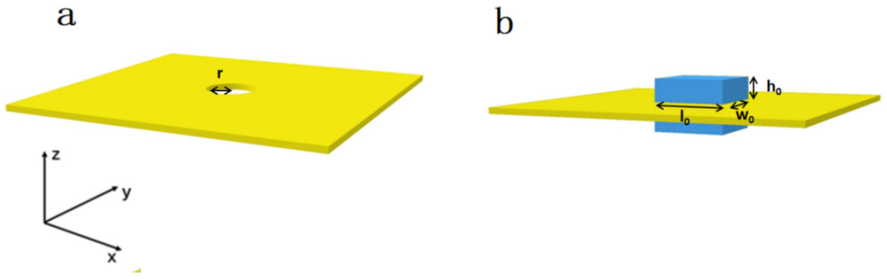
Abstract
:1. Introduction
2. Materials and Methods
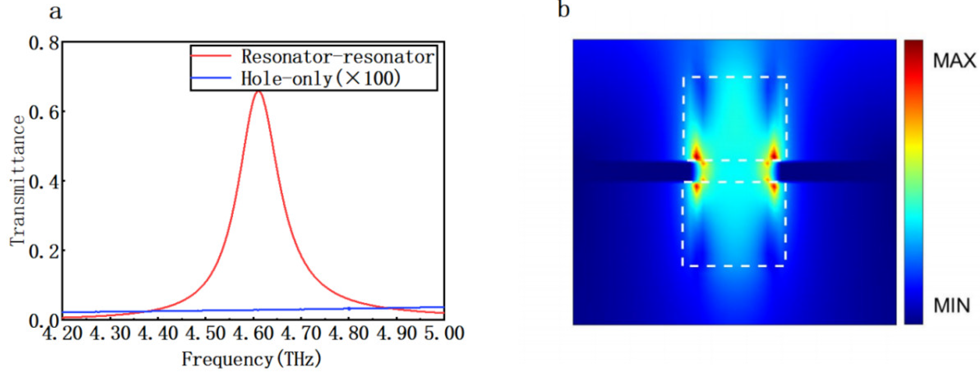
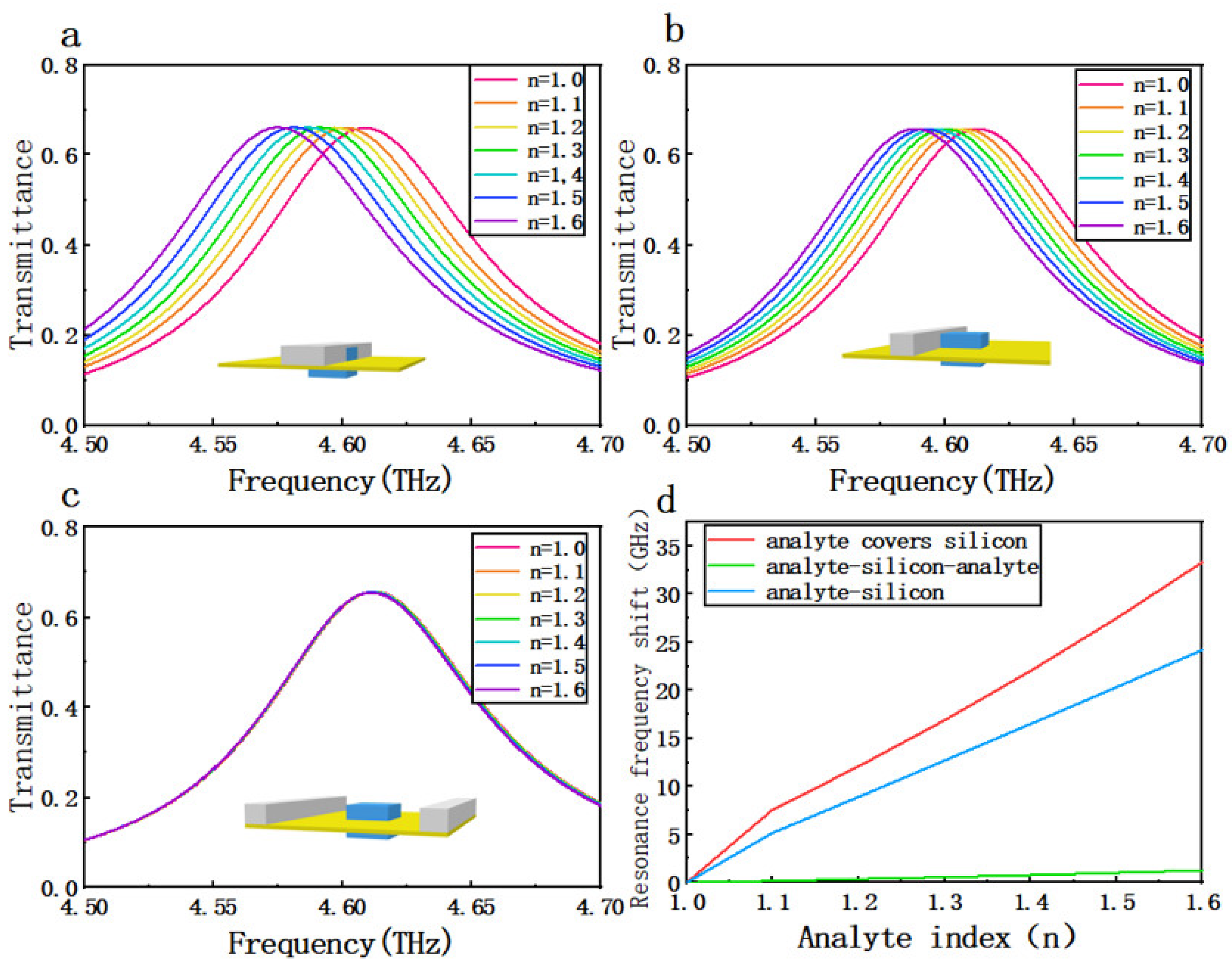
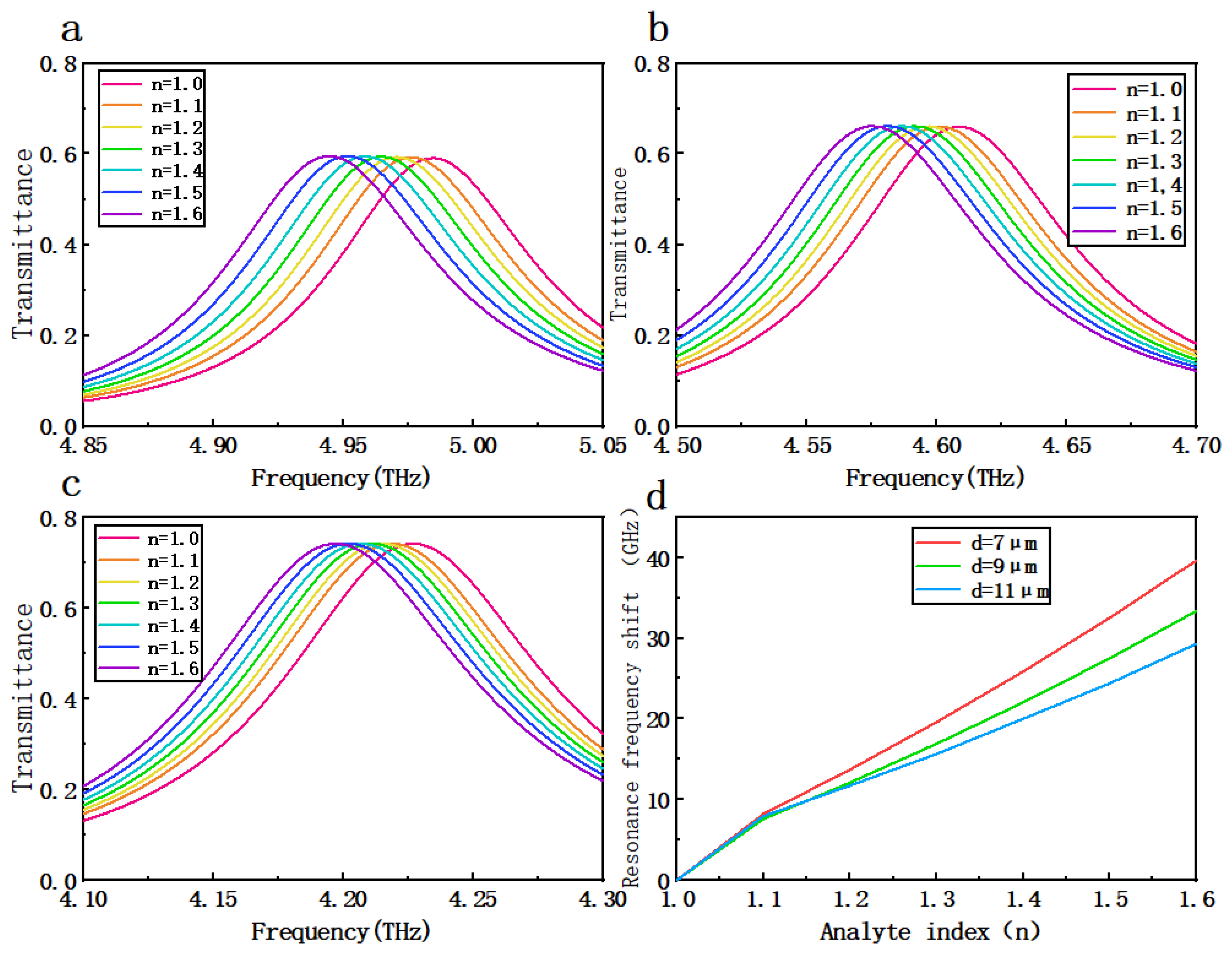
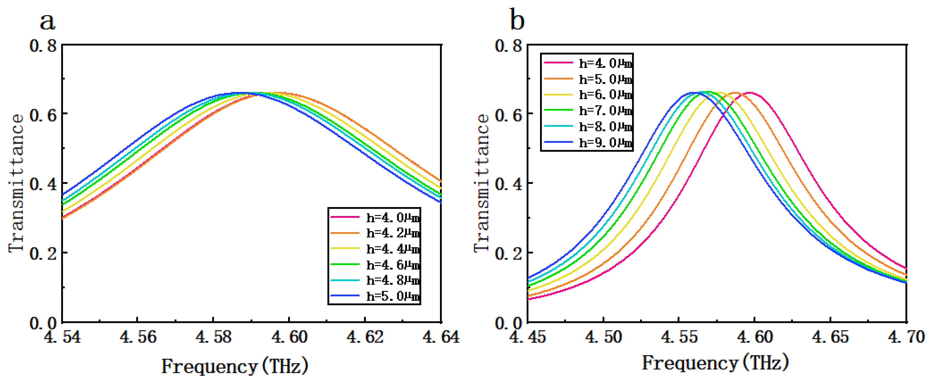
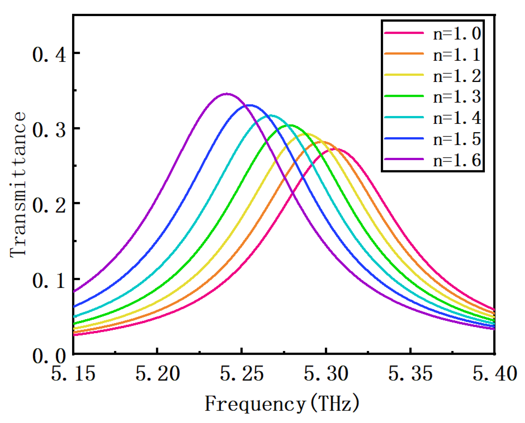
3. Results and Discussion
4. Conclusions
Author Contributions
Funding
Data Availability Statement
Conflicts of Interest
References
- Yang, J.; Qi, L.; Wu, L.; Lan, F.; Lan, C.; Tao, X.; Liu, Z. Research Progress of Terahertz Metamaterial Biosensors. Spectrosc. Spect. Anal. 2021, 41, 1669–1677. [Google Scholar]
- Tassin, P.; Koschny, T.; Soukoulis, C.M. Applied physics. Graphene for terahertz applications. Science 2013, 341, 620. [Google Scholar] [CrossRef] [PubMed] [Green Version]
- Zhou, H.; Yang, C.; Hu, D.; Li, D.; Hui, X.; Zhang, F.; Chen, M.; Mu, X. Terahertz biosensing based on bilayer metamaterialabsorbers toward ultra-high sensitivity and simple fabrication. Appl. Phys. Lett. 2019, 115, 143507. [Google Scholar] [CrossRef]
- Xu, W.; Xie, L.; Zhu, J.; Wang, W.; Ye, Z.; Ma, Y.; Tsai, C.Y.; Chen, S.; Ying, Y. Terahertz sensing of chlorpyrifos-methyl using metamaterials. Food Chem. 2017, 218, 330. [Google Scholar] [CrossRef] [PubMed]
- Qin, J.; Xie, L.; Ying, Y. A high-sensitivity terahertz spectroscopy technology for tetracycline hydrochloride detection using metamaterials. Food Chem. 2016, 211, 300. [Google Scholar] [CrossRef]
- Cong, L.; Tan, S.; Yahiaoui, R.; Yan, F.; Zhang, W.; Singh, R. Experimental demonstration of ultrasensitive sensing with terahertz metamaterial absorbers: A comparison with the metasurfaces. Appl. Phys. Lett. 2015, 106, 031107. [Google Scholar] [CrossRef]
- Ng, B.; Wu, J.; Hanham, S.M.; Fernández-Domínguez, A.I.; Klein, N.; Liew, Y.F.; Breese, M.B.H.; Hong, M.; Maier, S.A. Spoof plasmon surfaces: A novel platform for THz sensing. Adv. Opt. Mater. 2013, 1, 543. [Google Scholar] [CrossRef]
- Sun, Y.; Du, P.; Lu, X.; Xie, P.; Ullah, R. Terahertz spectroscopy of Bisphenol “A”,: AF”, “S”, “E” and the interrelationship between their molecular vibrations. Spectrochim. Acta Part A 2018, 209, 70. [Google Scholar] [CrossRef]
- Pendry, J.B.; Martín-Moreno, L.; Garcia-Vidal, F.J. Mimicking surface plasmons with structured surfaces. Science 2004, 305, 847–848. [Google Scholar] [CrossRef]
- Chau, Y.C.; Chao, C.C.; Jumat, S.Z.B.H.; Kooh, M.R.R.; Thotagamuge, R.; Lim, C.M.; Chiang, H. Improved Refractive Index-Sensing Performance of Multimode Fano-Resonance-Based Metal-Insulator-Metal Nanostructures. Nanomaterials 2021, 11, 2097. [Google Scholar] [CrossRef]
- Taie, R.; Serita, K.K.; Kitagishi, T.; Kawai, I.; Kawayama, H.; Murakami, M.; Tonouchi, M. Development of PDMS Microchannel Integrated Type Terahertz Chip. In Proceedings of the 2018 43rd International Conference on Infrared, Millimeter and Terahertz Waves (IRMMW-THz), Nagoya, Japan, 9–14 September 2018. [Google Scholar]
- Liu, J.; Fan, L.; Ku, J.; Mao, L. Absorber: A novel terahertz sensor in the application of substance identification. Opt. Quant. Electron. 2016, 48, 80. [Google Scholar] [CrossRef]
- Yan, D.; Li, J.; Wang, Y. High sensitivity terahertz refractive index sensor based on sunflower-shaped circular photonic crystal. Acta Phys. Sin. 2019, 68, 207801. [Google Scholar] [CrossRef]
- Saadeldin, A.S.; Hameed MF, O.; Elkaramany, E.M.; Obayya, S.S. Highly Sensitive Terahertz Metamaterial Sensor. IEEE Sens. J. 2019, 19, 7993–7999. [Google Scholar] [CrossRef]
- Wang, Y.; Cui, Z.; Zhang, X.; Zhang, X.; Zhu, Y.; Chen, S.; Hu, H. Excitation of Surface Plasmon Resonance on Multiwalled Carbon Nanotube Metasurfaces for Pesticide Sensors. ACS Appl. Mater. Interfaces 2020, 12, 52082–52088. [Google Scholar] [CrossRef]
- Song, J.; Shi, Y.; Li, M.; Liu, X.; Wang, X.; Yang, F.; Feng, H. Enhanced extraordinary terahertz transmission through coupling between silicon resonators. Nanoscale Adv. 2022, 4, 2494–2500. [Google Scholar] [CrossRef]
- Song, J.; Shi, Y.; Liu, X.; Li, M.; Wang, X.; Yang, F. Enhanced broadband extraordinary terahertz transmission through plasmon coupling between metal hemisphere and hole arrays. Opt. Mater. Express 2021, 11, 2700–2710. [Google Scholar] [CrossRef]
- Niu, K.; Huang, Z.; Wu, X. Extraordinary Optical Transmission Coupled to a Gain Medium through Periodic Arrays of Subwavelength Apertures. In Proceedings of the 2017 IEEE International Conference on Computational Electromagnetics (ICCEM), Kumamoto, Japan, 8–10 March 2017. [Google Scholar]
- Liu, H.; Lalanne, P. Microscopic theory of the extraordinary optical transmission. Nature 2008, 452, 728–731. [Google Scholar] [CrossRef]
- Bethe, H.A. Theory of Diffraction by Small Holes. Phys. Rev. 1944, 66, 163. [Google Scholar] [CrossRef]
- Wu, B.; Wang, Q. Discussion of the mechanism of extraordinary optical transmission in metallic gratings. In Proceedings of the 2006 International Symposium on Biophotonics, Nanophotonics and Metamaterials, Hangzhou, China, 16–18 October 2006. [Google Scholar]
- Ou, N.; Shyu, J.H.; Wu, J.C.; Wu, T.H. Extraordinary Optical Transmission Through Dielectric Hole-Array Coated with TbFeCo Thin Film. IEEE Trans. Magn. 2009, 45, 4027–4029. [Google Scholar] [CrossRef]
- Gan, Q.; Ding, Y.J.; Bartoli, F.J. “Rainbow” trapping and releasing at telecommunication wavelengths. Phys. Rev. Lett. 2009, 102, 056801. [Google Scholar] [CrossRef]
- Lu, Y.; Cheng, X.; Xu, M.; Xu, J.; Wang, J. Improved extraordinary transmission of light through a single nano-slit by exciting the hybrid state of Tamm and surface plasmon polaritons. In Proceedings of the 2017 Conference on Lasers and Electro-Optics Pacific Rim (CLEO-PR), Singapore, 31 July–4 August 2017. [Google Scholar]
- Gordon, R.; Choudhury, A.I.K.; Eftekhari, F. Eccentric Coaxial Gap-Plasmon Aperture Arrays for Enhanced Extraordinary Optical Transmission and Applications. In Proceedings of the CLEO/Europe and EQEC 2009 Conference Digest, Optica, Munich, Germany, 14–19 June 2009. [Google Scholar]
- Palik, E.D. Handbook of Optical Constants of Solids; Academic Press: Cambridge, MA, USA, 1998; Volume 3. [Google Scholar]
- Genet, C.; Ebbesen, T.W. Light in tiny holes. Nature 2007, 445, 39–46. [Google Scholar] [CrossRef] [PubMed]
- Ma, L.; Cui, Z.; Zhu, D.; Yue, L.; Hou, L.; Wang, Y. Metamaterials Sensor Based on Multiband Terahertz Absorber. In Proceedings of the 2019 44th International Conference on Infrared, Millimeter, and Terahertz Waves (IRMMW-THz), Paris, France, 1–6 September 2019. [Google Scholar]
- Liu, J.; Jasim, I.; Roman, M.; Yang, Y.; Qu, C.; Huang, J.; Kinzel, E.; Almasri, M. Functional Plasmonic Fiber-Optic Based Sensors Using Low-Cost Microsphere Photolithography. In Proceedings of the 2019 20th International Conference on Solid-State Sensors, Actuators and Microsystems & Eurosensors XXXIII (Transducers & Eurosensors XXXIII), Estrel Hotel & Congress Center, Sonnenallee, Germany, 23–27 June 2019. [Google Scholar]
- Yin, S.; Hu, F.; Chen, X.; Han, J.; Chen, T.; Xiong, X.; Zhang, W. Ruler equation for precisely tailoring the resonance frequency of terahertz U-shaped metamaterials. J. Opt. 2019, 21, 025101. [Google Scholar] [CrossRef]
- Liang, Z.; Zhong, R.; Fang, Z.; Ma, A.; Yong, L.; Wang, Y.; Liu, S. Extremely high Q-factor terahertz metamaterial microfluidic sensor based on InN Strips. In Proceedings of the 2021 46th International Conference on Infrared, Millimeter and Terahertz Waves (IRMMW-THz), Chengu, China, 29 August–3 September 2021. [Google Scholar]
- Sotskya, A.B.; Nazarovb, M.M.; Miheeva, S.S.; Sotskayac, L.I. Sensitivity of Reflecting Terahertz Sensors of Aqueous Solutions. Tech. Phys. 2021, 66, 305–315. [Google Scholar] [CrossRef]
- Beruete, M.; Jáuregui-López, I. Terahertz Sensing Based on Metasurfaces. Adv. Opt. Mater. 2020, 8, 1900721. [Google Scholar] [CrossRef] [Green Version]
- Krapels, K.; Salmon, N.; Jacobs, E. Millimetre Wave and Terahertz Sensors and Technology V. Proc. SPIE-Int. Soc. Opt. Eng. 2012, 8544, 854401. [Google Scholar]
- Liang, L.; Wen, L.; Jiang, C.; Chen, Q. Research progress of terahertz sensor based on artificial microstructure. Infrared Laser Eng. 2019, 48, 203001. [Google Scholar] [CrossRef]
- Soltani, A.; Neshasteh, H.; Mataji-Kojouri, A.; Born, N.; Balzer, J.; Shahabadi, M.; Castro-Camus, E.; Koch, M. Terahertz waveguide sensor for small volume liquid samples. In Proceedings of the 2016 41st International Conference on Infrared, Millimeter and Terahertz waves (IRMMW-THz), Copenhagen, Denmark, 25–30 September 2016. [Google Scholar]


Publisher’s Note: MDPI stays neutral with regard to jurisdictional claims in published maps and institutional affiliations. |
© 2022 by the authors. Licensee MDPI, Basel, Switzerland. This article is an open access article distributed under the terms and conditions of the Creative Commons Attribution (CC BY) license (https://creativecommons.org/licenses/by/4.0/).
Share and Cite
Sun, K.; Fang, J.; Shi, Y.; Shi, S.; Zhang, S.; Song, J.; Li, M.; Wang, X.; Yang, F. Terahertz Refractive Index Sensor Based on Enhanced Extraordinary Optical Transmission. Crystals 2022, 12, 1616. https://doi.org/10.3390/cryst12111616
Sun K, Fang J, Shi Y, Shi S, Zhang S, Song J, Li M, Wang X, Yang F. Terahertz Refractive Index Sensor Based on Enhanced Extraordinary Optical Transmission. Crystals. 2022; 12(11):1616. https://doi.org/10.3390/cryst12111616
Chicago/Turabian StyleSun, Kaixiang, Jiukai Fang, Yanpeng Shi, Shengnan Shi, Shan Zhang, Jinmei Song, Meiping Li, Xiaodong Wang, and Fuhua Yang. 2022. "Terahertz Refractive Index Sensor Based on Enhanced Extraordinary Optical Transmission" Crystals 12, no. 11: 1616. https://doi.org/10.3390/cryst12111616