
The Impact of Laminations on the Mechanical Strength of Carbon-Fiber Composites for Prosthetic Foot Fabrication
 , , , , and
Abstract
:1. Introduction
2. Materials and Methods
2.1. Materials
- Black 100% 3 K 200 gsm carbon-fiber cloth with tensile strength 4380 Mpa (thickness = 0.2 mm);
- Two parts epoxy resin Araldite® LY556;
- Hardener Aradur® 22962;
- Mold releasing wax;
- Plywood for mold preparation.
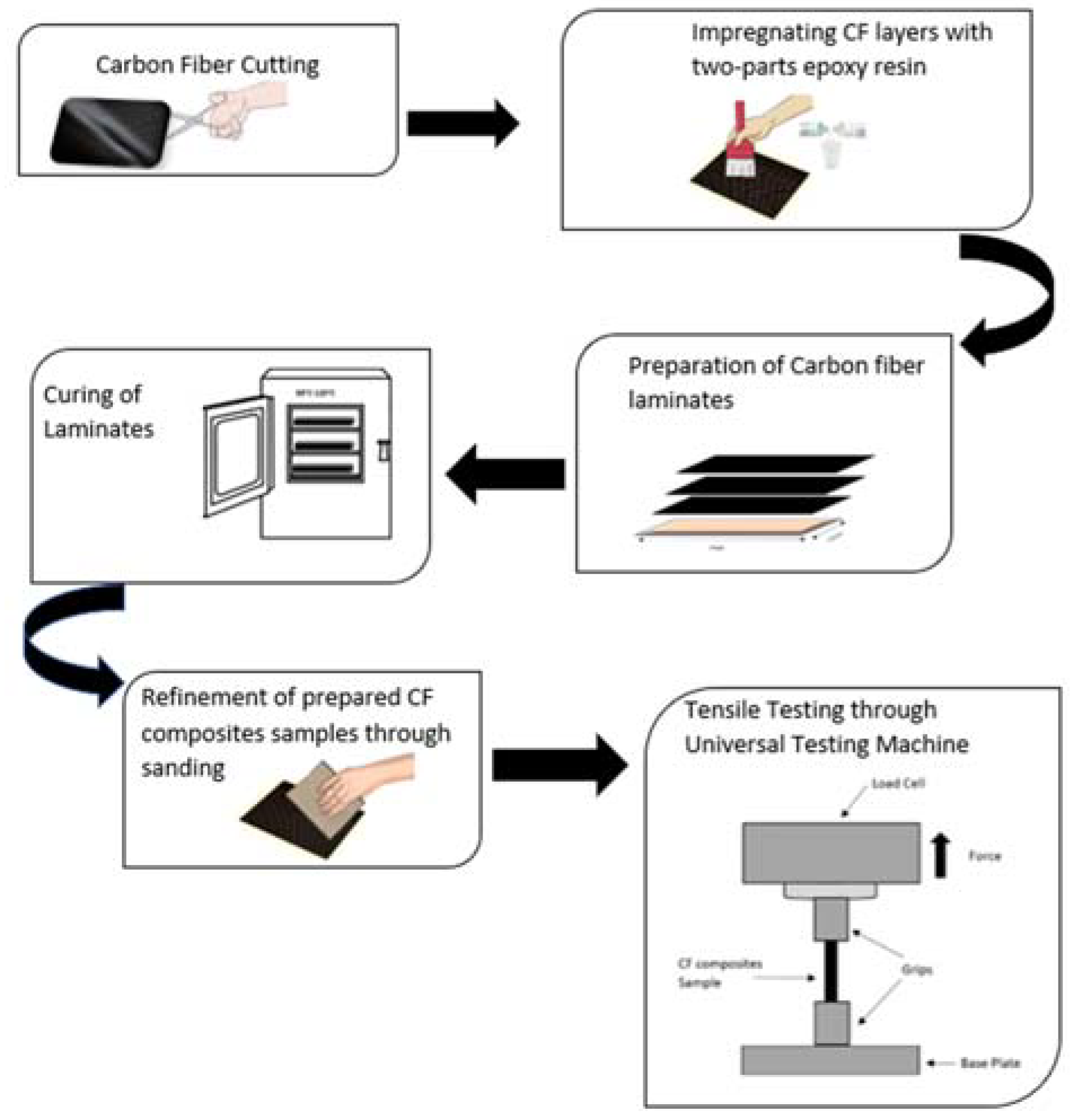
2.2. Experiment Protocol
Specimen Preparation
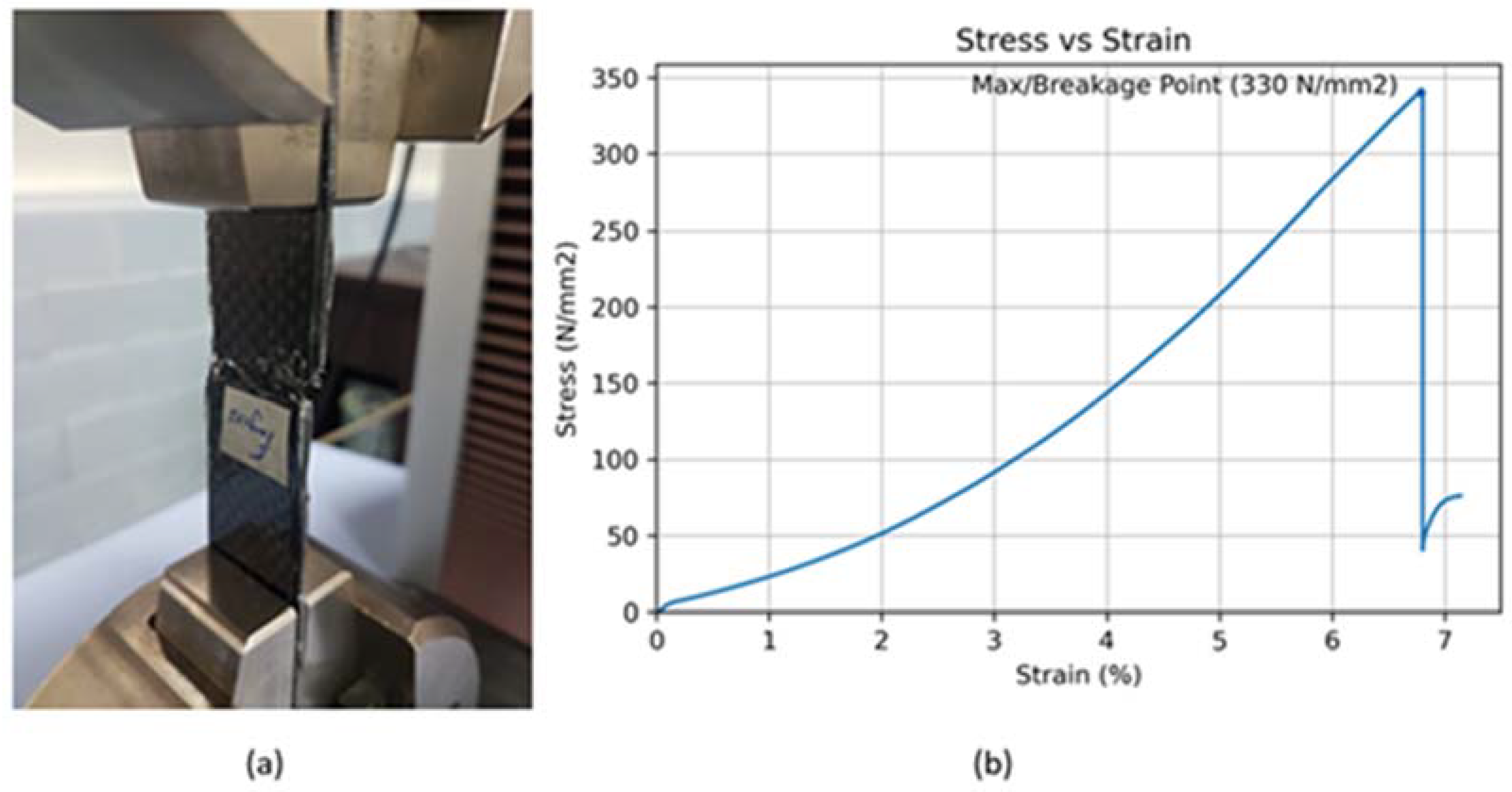
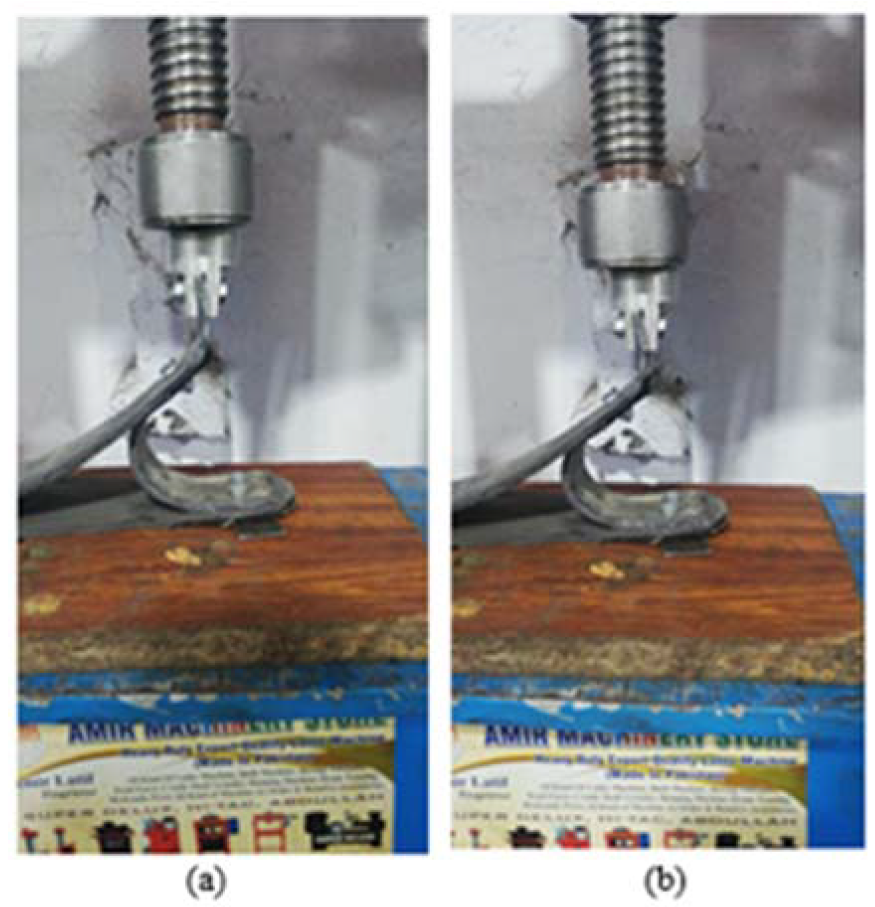
2.3. Tensile Testing
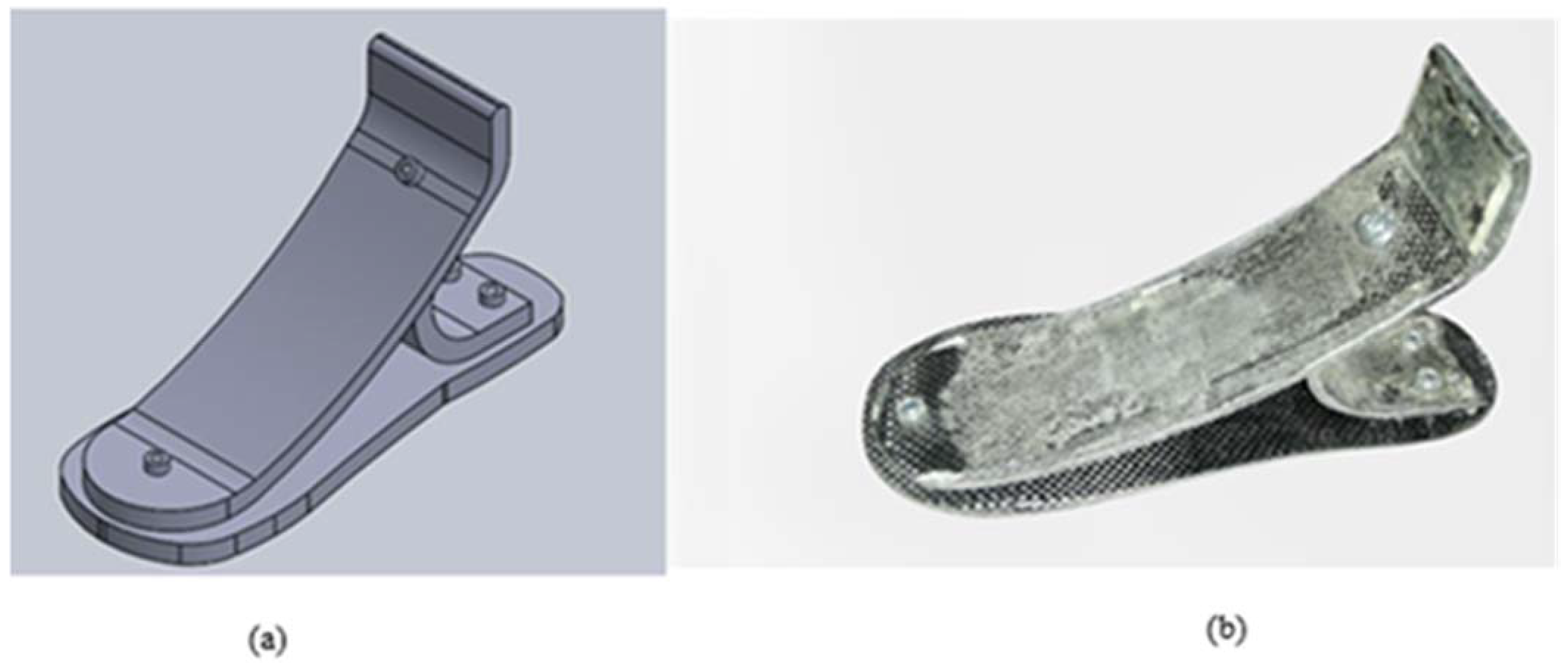
2.4. Design Concept of Prosthetic Foot
3. Results
Prosthetic Foot Prototype Results
4. Discussion
5. Conclusions
Author Contributions
Funding
Institutional Review Board Statement
Informed Consent Statement
Data Availability Statement
Acknowledgments
Conflicts of Interest
References
- Bhargava, R. The Jaipur Foot and the ‘Jaipur Prosthesis’. Indian J. Orthop. 2019, 53, 5. [Google Scholar] [CrossRef]
- South, B.J.; Fey, N.P.; Bosker, G.; Neptune, R.R. Manufacture of Energy Storage and Return Prosthetic Feet Using Selective Laser Sintering. J. Biomech. Eng. 2009, 132, 015001. [Google Scholar] [CrossRef]
- Meier, M.R. Design and development of appropriate technology for low-income countries: Preliminary field investigation of the Shape & Roll prosthetic foot in El Salvador, Central America. Capabilities 2002, 11, 1–2. [Google Scholar]
- Hahl, J.; Taya, M. Experimental and numerical predictions of the ultimate strength of a low-cost composite transtibial prosthesis. J. Rehabil. Res. Dev. 2000, 37, 405–413. [Google Scholar] [PubMed]
- Arya, A.P.; Klenerman, L. The Jaipur foot. J. Bone Jt. Surgery. Br. Vol. 2008, 90, 1414–1421. [Google Scholar] [CrossRef]
- Jagannatha, T.D.; Harish, G. Mechanical properties of carbon/glass fiber reinforced epoxy hybrid polymer composites. Int. J. Mech. Eng. Robot. Res. 2015, 4, 131–137. [Google Scholar]
- Nolan, L. Carbon fibre prostheses and running in amputees: A review. Foot Ankle Surg. 2008, 14, 125–129. [Google Scholar] [CrossRef] [PubMed]
- Campbell, F.C. Structural Composite Materials; Google Books; ASM International: Materials Park, OH, USA, 2010. [Google Scholar]
- Pham, H.T.; Phan, T.V.; Mai, V.T. Optimization Design of a Carbon Fibre Prosthetic Foot for Amputee. Acta Sci. Orthop. 2020, 3, 16–21. [Google Scholar] [CrossRef]
- Sau-Fun, N.; Chi-Leung, H.; Lai-Fan, W. Development of medical garments and apparel for the elderly and the disabled. Textile Progress 2011, 43, 235–285. [Google Scholar] [CrossRef]
- Maruo, Y.; Nishigawa, G.; Irie, M.; Yoshihara, K.; Minagi, S. Flexural properties of polyethylene, glass and carbon fiber-reinforced resin composites for prosthetic frameworks. Acta Odontol. Scand. 2015, 73, 581–587. [Google Scholar] [CrossRef]
- Scholz, M.-S.; Blanchfield, J.; Bloom, L.; Coburn, B.; Elkington, M.; Fuller, J.; Gilbert, M.; Muflahi, S.; Pernice, M.; Rae, S.; et al. The use of composite materials in modern orthopaedic medicine and prosthetic devices: A review. Compos. Sci. Technol. 2011, 71, 1791–1803. [Google Scholar] [CrossRef]
- Liu, L.; Jia, C.; He, J.; Zhao, F.; Fan, D.; Xing, L.; Wang, M.; Wang, F.; Jiang, Z.; Huang, Y. Interfacial characterization, control and modification of carbon fiber reinforced polymer composites. Compos. Sci. Technol. 2015, 121, 56–72. [Google Scholar] [CrossRef]
- Wang, J.; Song, F.; Ding, Y.; Shao, M. The incorporation of graphene to enhance mechanical properties of polypropylene self-reinforced polymer composites. Mater. Des. 2020, 195, p. 109073. [Google Scholar] [CrossRef]
- Thongchom, C.; Refahati, N.; Saffari, P.R.; Saffari, P.R.; Niyaraki, M.N.; Sirimontree, S.; Keawsawasvong, S. An Experimental Study on the Effect of Nanomaterials and Fibers on the Mechanical Properties of Polymer Composites. Buildings 2021, 12, 7. [Google Scholar] [CrossRef]
- Khalid, M.Y.; Arif, Z.U.; Ahmed, W.; Arshad, H. Evaluation of tensile properties of fiber metal laminates under different strain rates. Proc. Inst. Mech. Eng. Part E J. Process. Mech. Eng. 2022, 236, 556–564. [Google Scholar] [CrossRef]
- Bheel, N.; Tafsirojjaman, T.; Liu, Y.; Awoyera, P.; Kumar, A.; Keerio, M.A. Experimental Study on Engineering Properties of Cement Concrete Reinforced with Nylon and Jute Fibers. Buildings 2021, 11, 454. [Google Scholar] [CrossRef]
- Dziaduszewska, M.; Wekwejt, M. Composites in energy storing prosthetic feet. Eur. J. Med. Technol. 2018, 3, 16–22. [Google Scholar]
- Oleiwi, J.K.; Hadi, A.N. Experimental and numerical investigation of lower limb prosthetic foot made from composite polymer blends. Int. J. Mech. Prod. Eng. Res. Dev. 2018, 8, 1319–1330. [Google Scholar]
- Abbas, S.M.; Resan, K.K.; Muhammad, A.K.; Al-Waily, M. Mechanical and Fatigue Behaviors of Prosthetic for Partial Foot Amputation with Various Composite Materials Types Effect. Int. J. Mech. Eng. Technol. (IJMET) 2018, 9, 383–394. [Google Scholar]
- Barrios-Muriel, J.; Romero-Sánchez, F.; Alonso-Sánchez, F.J.; Salgado, D.R. Advances in Orthotic and Prosthetic Manufacturing: A Technology Review. Materials 2020, 13, 295. [Google Scholar] [CrossRef] [Green Version]
- Jweeg, M.J.; Hammood, A.S.; Al-Waily, M. Experimental and theoretical studies of mechanical properties for reinforcement fiber types of composite materials. Int. J. Mech. Mechatron. Eng. 2012, 12, 62. [Google Scholar]
- Khare, J.M.; Dahiya, S.; Gangil, B.; Ranakoti, L. Influence of different resins on Physico-Mechanical properties of hybrid fiber reinforced polymer composites used in human prosthetics. Mater. Today: Proc. 2020, 38, 345–349. [Google Scholar] [CrossRef]
- Rahmani, H.; Najafi, S.H.M.; Ashori, A. Mechanical performance of epoxy/carbon fiber laminated composites. J. Reinf. Plast. Compos. 2014, 33, 733–740. [Google Scholar] [CrossRef]
- Hadi, A.N.; Oleiwi, J.K. Improve Flexural Strength of PMMA/SR Polymer Blend by Reinforcement with Carbon Fibers as Prosthetic Foot Polymer Material. Int. J. Appl. Or Innov. Eng. Manag. 2015, 4, 172–176. [Google Scholar]
- Muhammed, A.M. Experimental investigation of tensile and fatigue stresses for orthotic/prosthetic composite materials with varying fiber (perlon, e-glass and carbon). ARPN J. Eng. Appl. Sci. 2016, 11, 12820–12827. [Google Scholar]
- Pulikkalparambil, H.; Rangappa, S.M.; Siengchin, S.; Parameswaranpillai, J. Introduction to Epoxy Composites. In Epoxy Composites, 1st ed.; Parameswaranpillai, J., Pulikkalparambil, H., Rangappa, S.M., Siengchin, S., Eds.; Wiley: Weinheim Germany, 2021; pp. 1–21. [Google Scholar] [CrossRef]
- Muralidhara, B.; Babu, S.K.; Suresha, B. Utilizing vacuum bagging process to prepare carbon fiber/epoxy composites with improved mechanical properties. Mater. Today: Proc. 2020, 27, 2022–2028. [Google Scholar] [CrossRef]
- Chen, A.Y.; Baehr, S.; Turner, A.; Zhang, Z.; Gu, G.X. Carbon-fiber reinforced polymer composites: A comparison of manufacturing methods on mechanical properties. Int. J. Light. Mater. Manuf. 2021, 4, 468–479. [Google Scholar] [CrossRef]
- Al-Khazraji, K.; Kadhim, J.; Ahmed, P.S. Tensile and fatigue characteristics of lower-limb prosthetic socket made from composite materials. In Proceedings of the 2012 International Conference on Industrial Engineering and Operations Management, Istanbul, Turkey, 3–6 July 2012; pp. 847–852. [Google Scholar]
- Elkington, M.; Bloom, D.; Ward, C.; Chatzimichali, A.; Potter, K. Hand layup: Understanding the manual process. Adv. Manuf. Polym. Compos. Sci. 2015, 1, 138–151. [Google Scholar] [CrossRef] [Green Version]
- de Paiva, J.M.F.; Santos, A.D.N.D.; Rezende, M.C. Mechanical and morphological characterizations of carbon fiber fabric reinforced epoxy composites used in aeronautical field. Mater. Res. 2009, 12, 367–374. [Google Scholar] [CrossRef] [Green Version]
- Haislip, T.S. Comparative Analysis Of Two Prosthetic Foot Designs Using Cyclical Load Testing And Cad Simulation. Ph.D. Thesis, Mercer University, Macon, GA, USA, 2019. [Google Scholar]
- Wang, J.; Chen, L.; Shen, W.; Zhu, L. Research on Tensile Properties of Carbon Fiber Composite Laminates. Polymers 2022, 14, 2318. [Google Scholar] [CrossRef]
- Khan, H.A.; Nigar, M.; Chaudhry, I.A. Tensile Behavior of Unidirectional Carbon Reinforced Composites for Aerospace Structures under Varying Strain Rates. Appl. Mech. Mater. 2015, 798, 357–361. [Google Scholar] [CrossRef]
- Karthik, K.; Rajamani, D.; Manimaran, A.; Udayaprakash, J. Evaluation of tensile properties on Glass/Carbon/Kevlar fiber reinforced hybrid composites. Mater. Today: Proc. 2020, 39, 1655–1660. [Google Scholar] [CrossRef]


| Properties | Epoxy Resin Araldite® LY556 | Hardener Aradur® 22962 |
|---|---|---|
| Viscosity at 25 °C (ISO 12058–1) | 10,000–12,000 mPa s | 5–20 mPa s |
| Density at 25 °C (ISO 1675) | 1.15–1.20 g/cm3 | 0.89–0.90 g/cm3 |
| Flash Point (ISO 2719) | >200 °C | ≥110 °C |
| Storage Temperature | 2–40 °C | 2–40 °C |
| Epoxy content (ISO 3000) | 5.30–5.45 eq/kg | ____ |
| Epoxy equivalent (ISO 3000) | 183–189 g/eq | ____ |
| Araldite® LY556/Aradur® 22962 | Number of CF Laminations | Load Rate |
|---|---|---|
| 100:30 | 2 layers 4 layers | 2 mm/min, 2 mm/min |
| 2 layers | 5 mm/min | |
| 6 layers | 5 mm/min | |
| 10 layers | 5 mm/min |
| Sample | Time (sec) | Stress (N/mm2) | Strain (%) | Force (N) | Displacement (mm) | Stroke (mm) |
|---|---|---|---|---|---|---|
| Sample 1 | 0 | −0.06769 | 0 | −2.26498 | 0 | 0 |
| 0.1 | −0.13361 | 0.044444 | −0.54995 | 0.005333 | 0.005333 | |
| 27.23 | 251.2207 | 18.88733 | 1034.025 | 2.266479 | 2.266479 | |
| 45.36 | 208.7001 | 31.47639 | 859.0095 | 3.777167 | 3.777167 | |
| 55.26 | 167.9828 | 38.35209 | 691.4171 | 4.60225 | 4.60225 | |
| Sample 2 | 0 | −2.85135 | 0 | −98.3715 | 0 | 0 |
| 0.1 | −2.77994 | 0.002438 | −95.9078 | 0.002146 | 0.002146 | |
| 179.64 | 330.9781 | 6.805351 | 11,418.74 | 5.988708 | 5.988708 | |
| 188.58 | 75.94242 | 7.141951 | 2620.013 | 6.284916 | 6.284916 | |
| 188.4 | 75.85056 | 7.135014 | 2616.844 | 6.278812 | 6.278812 | |
| Sample 3 | 0 | −0.06769 | 0 | −2.26498 | 0 | 0 |
| 0.1 | 0.266715 | 0.006849 | 8.924802 | 0.005479 | 0.005479 | |
| 52.1 | 576.079 | 5.426823 | 19276.75 | 4.341458 | 4.341458 | |
| 52.12 | 540.9233 | 5.429844 | 18100.37 | 4.34z3875 | 4.343875 | |
| 52.18 | −0.29973 | 5.432031 | −10.0295 | 4.345625 | 4.345625 |
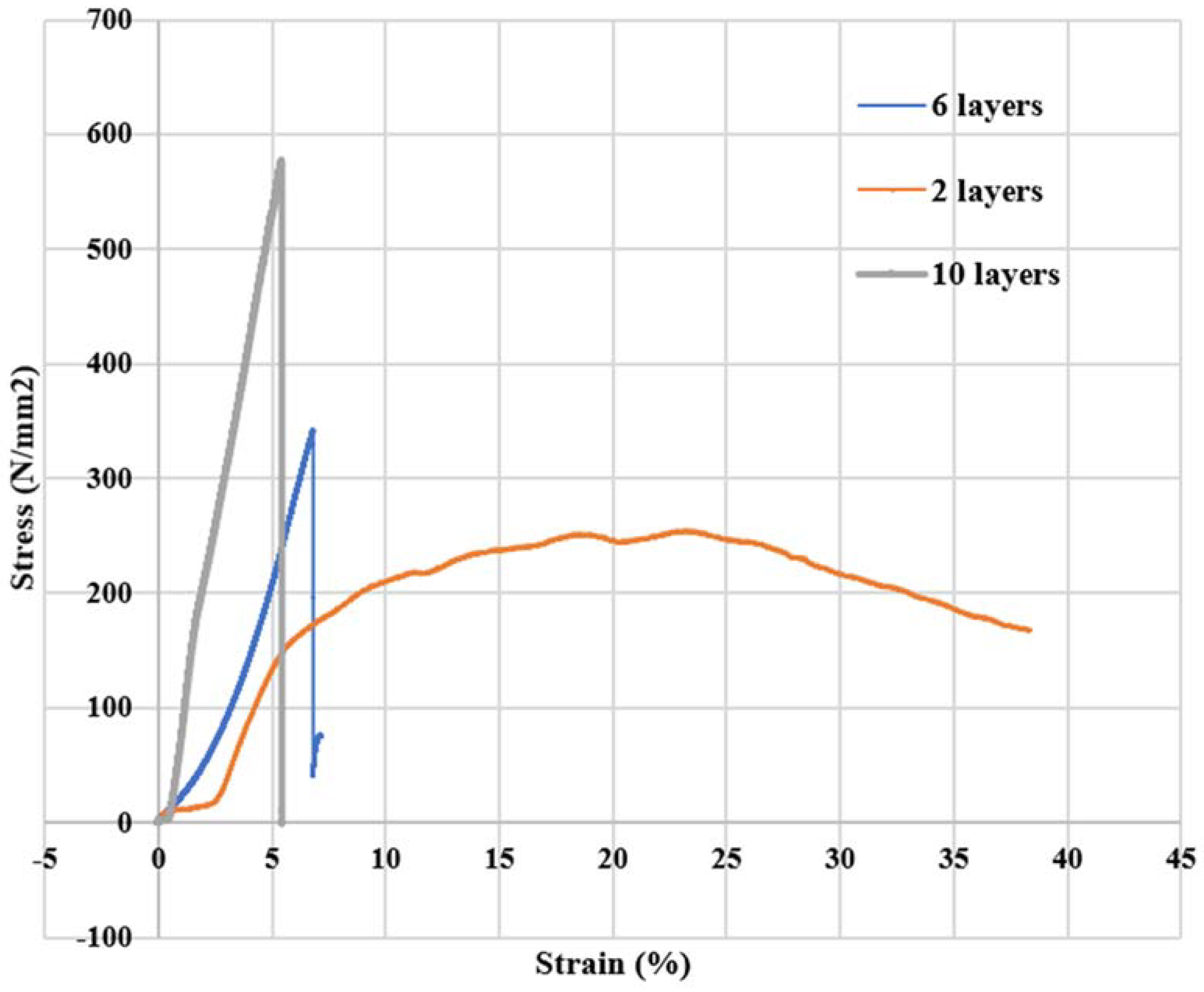
| CF Layers | Load Rate | Epoxy: Resin | Mechanical Strength (N/mm2) |
|---|---|---|---|
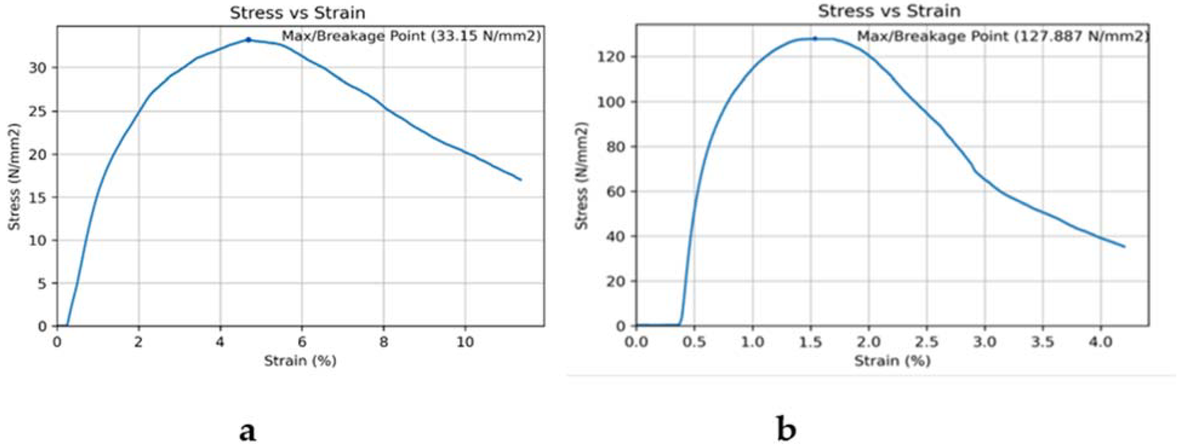
| 2 | 2 mm/min | 100:30 | 33.15 |
| 4 | 2 mm/min | 100:30 | 127.88 |
| 2 | 5 mm/min | 100:30 | 254.51 |
| 6 | 5 mm/min | 100:30 | 341.54 |
| 10 | 5 mm/min | 100:30 | 576.07 |
| Previous Studies | Materials | Fabrication Method | Tensile Strength | Conclusion |
|---|---|---|---|---|
| (Muralidhara et al. 2020) | Carbon fiber: T800CF/Ep, T700CF/Ep, and T300CF/Ep Epoxy Resin: Araldite LY1564 Hardener: Aradur 22962 | Hand layup method with vacuum bagging process | Approximately 680 MPa, 630 MPa, and 330 Mpa. | (2–6) % increase in the mechanical strength by vacuum bagging in comparison to the hand layup method. |
| (Chen et al. 2021) | Unidirectional carbon-fiber sheets Two parts epoxy resin | Hand layup method | The mean tensile strength of 13 CF samples showed an average tensile strength equal to 164.57. | The hand layup method provided higher stiffness and mechanical strength in flexure. |
| (Pham et al. 2020) | Dry carbon-fiber fabric Polyester resin | Hand layup method with vacuum bagging | Specimen tensile strength was found to be 243 Mpa. | The manufactured prosthetic foot prototype will enable forward propulsion lowering the impact force upon residual organs. |
| [36] (Karthik et al. 2021) | Glass, carbon, and Kevlar fibers | Hand layup method with compression molding | A mixture of carbon and Kevlar fibers indicated the highest tensile strength of 385.09 Mpa. | Carbon-Kevlar-Carbon composites showed fewer surface defects under stress. |
Publisher’s Note: MDPI stays neutral with regard to jurisdictional claims in published maps and institutional affiliations. |
© 2022 by the authors. Licensee MDPI, Basel, Switzerland. This article is an open access article distributed under the terms and conditions of the Creative Commons Attribution (CC BY) license (https://creativecommons.org/licenses/by/4.0/).
Share and Cite
Sehar, B.; Waris, A.; Gilani, S.O.; Ansari, U.; Mushtaq, S.; Khan, N.B.; Jameel, M.; Khan, M.I.; Bafakeeh, O.T.; Tag-ElDin, E.S.M. The Impact of Laminations on the Mechanical Strength of Carbon-Fiber Composites for Prosthetic Foot Fabrication. Crystals 2022, 12, 1429. https://doi.org/10.3390/cryst12101429
Sehar B, Waris A, Gilani SO, Ansari U, Mushtaq S, Khan NB, Jameel M, Khan MI, Bafakeeh OT, Tag-ElDin ESM. The Impact of Laminations on the Mechanical Strength of Carbon-Fiber Composites for Prosthetic Foot Fabrication. Crystals. 2022; 12(10):1429. https://doi.org/10.3390/cryst12101429
Chicago/Turabian StyleSehar, Bakhtawar, Asim Waris, Syed Omer Gilani, Umar Ansari, Shafaq Mushtaq, Niaz B. Khan, Mohammed Jameel, M. Ijaz Khan, Omar T. Bafakeeh, and El Sayed Mohamed Tag-ElDin. 2022. "The Impact of Laminations on the Mechanical Strength of Carbon-Fiber Composites for Prosthetic Foot Fabrication" Crystals 12, no. 10: 1429. https://doi.org/10.3390/cryst12101429