1. Introduction
Liquid argon as a scintillation material has been applied in many nuclear and particle physics experiments [
1,
2,
3,
4,
5,
6,
7,
8,
9,
10,
11,
12,
13,
14]. The pure liquid argon yields up to 50,000 photons/MeV [
15,
16,
17] with peak wavelength of 128 nm [
18,
19]. Pure liquid argon is transparent to its own scintillation radiation because scintillation photons have energy lower than the atomic argon first excited state [
20]. Pure argon is easy to produce in large quantities and at a low cost [
2]. It is often used as the detection medium in those low background experiments such as dark matter detection [
1,
2,
3,
8,
9,
10,
11,
12,
13,
14], the search for the neutrinoless double-β decay [
6,
7], and neutrino scattering [
4,
5]. In those experiments, liquid argon is used in the low background detectors, such as in a liquid scintillation veto detector [
3,
6,
7,
10,
11,
12] shielding and vetoing the background rays, the time projection chamber (TPC) [
1,
4,
9,
10,
11,
12,
13,
14], and the single-phase scintillation detector [
5,
8].
The external background in liquid argon detectors is mainly caused by natural radioactive isotopes and the cosmic rays [
21]. Detected in underground laboratories, the liquid scintillator veto detector is proficient in shielding and vetoing radiogenic and cosmogenic neutrons, γ rays, and cosmic muons; the water Cherenkov detector, also proficient in shielding and vetoing cosmic muons, can depress the external background [
9]. The internal background comes from the radioactivity of the detector target material, such as
39Ar [
4,
8,
21],
85Kr [
4], the scattering background of solar neutrinos and electrons, and
210Pb from radon pollution [
21]. To reduce the internal background, on one hand, the pulse shape discrimination (PSD) [
5,
8,
21] ability of liquid argon can be relied on, on the other hand, low radioactive argon can be utilized.
A defect in liquid argon detectors is the background caused by the diffusion of radioactive isotopes, such as radon, in scintillators (liquid phase). Radon is produced in the argon circulation pipelines and liquid argon containers [
21]. However, the solid argon as a scintillation material of the detector can inhibit the diffusion of radioactive isotopes in a solid phase scintillator to depress the background.
In the solid argon detector, only liquid nitrogen is needed to maintain the solid argon, so there is no circulation device which is necessary in the liquid argon detector. The entire structure of a solid argon detector is not complicated and without many components needed in the case of liquid argon detectors. Hence the total sources of radioactive isotopes brought into the detector are reduced, and the background in the detector is further depressed.
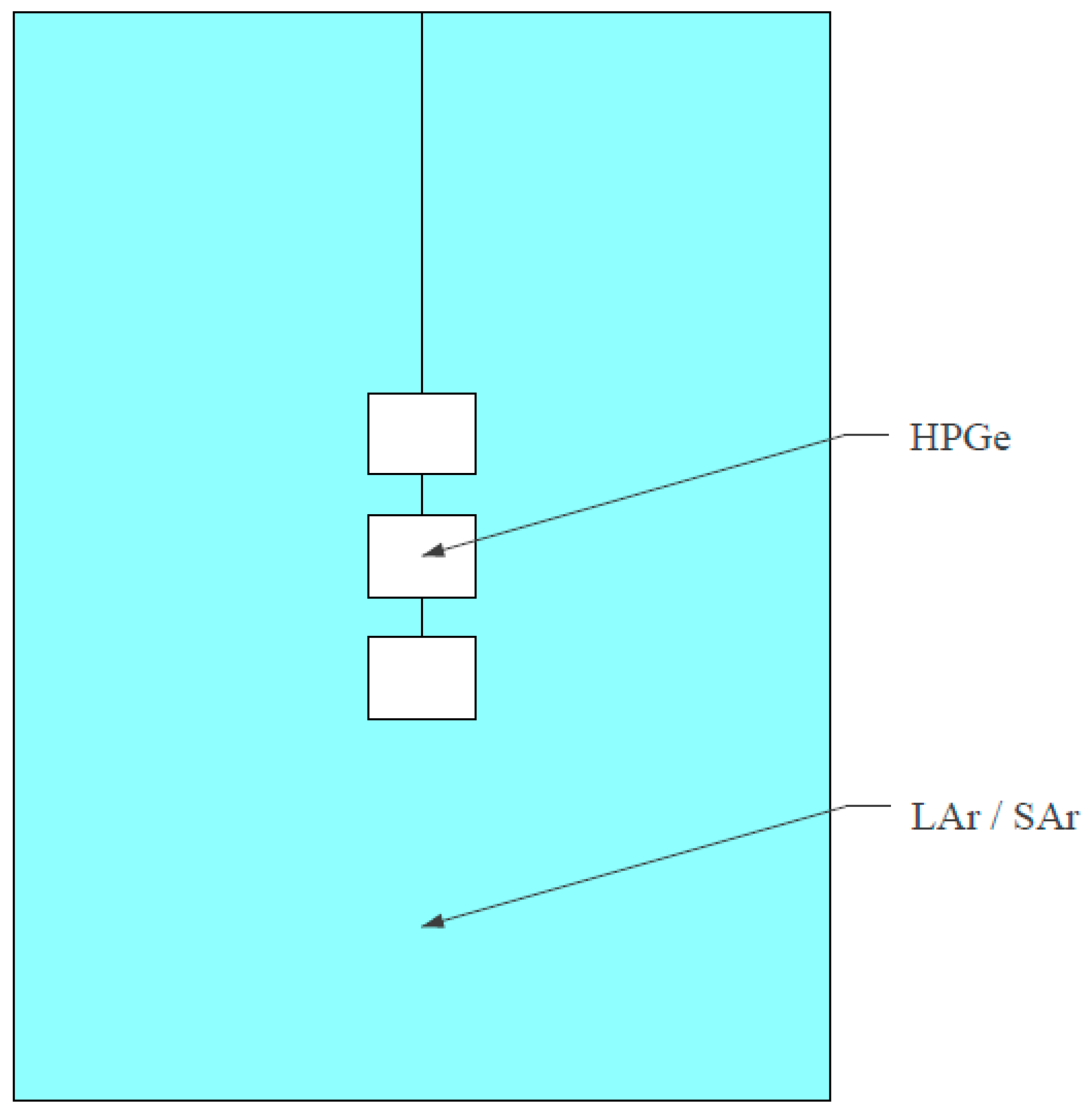
In China Dark matter EXperiment (CDEX), the detection system in CDEX-300 (for the introduction of CDEX-300, please consult [
22,
23]) is mainly composed of two parts: the central main detector called the high-purity germanium (HPGe) detectors array and the surrounding veto detector called the liquid argon scintillation detector, as shown schematically in
Figure 1. When external background rays pass through the scintillation detector to the HPGe detector, the scintillation detector gives a veto signal. Similarly, when background rays pass from the HPGe detector to the scintillation detector, a veto signal is also given. The charged particle diffusion and migration in solid argon is very weak. The liquid argon veto detector can be upgraded into the solid argon veto detector in the future for a lower background. On the one hand, the cosmogenic radioactive isotopes generated in high-purity germanium crystals (such as
60Co,
68Ge) [
24,
25], natural radioactive isotopes (U-chain and Th-chain) [
4,
26] and cosmogenic radioactive isotopes in structural materials, electronic components, and cables, etc., are the background source in high-purity germanium detectors; the solid argon veto detector can depress these backgrounds. On the other hand, the cosmogenic radioactive isotopes in argon, such as
39Ar and
42Ar (
42Ar decays into
42K) [
26,
27,
28], and radioactive isotopes produced by the decay of natural radioactive isotopes (U-chain and Th-chain) cannot easily drift to the surface of the HPGe detectors in solid argon to produce background signals.
Moreover, solid argon has a higher density (liquid argon has a density of about 1.4 × 10
3 kg/m
3 and solid argon has a density of about 1.6 × 10
3 kg/m
3) [
29,
30] and hence a higher detection efficiency (the higher the density, the more atoms in the per unit volume and the greater the linear attenuation coefficient of a scintillator to γ rays) as a scintillator than the liquid argon. Argon purification is also easily achieved due to the development of the electronics industry, so the background of an argon detector can be reduced to a very low level. Xenon and argon are largely used as the scintillation materials in rare gases. Argon is much cheaper and more easily available than xenon.
According to the advantages discussed above, solid argon has a great potential in the low background detection experiments, such as in dark matter detection and neutrino scattering, since it is especially helpful and much easier to get the lower background in the larger active volume which is required in those experiments compared to liquid argon.
Solid argon has been obtained in past studies [
31,
32]. A number of interesting works were focused on the rare gas solid (RGS), especially on their fluorescence properties [
19,
31,
32,
33,
34,
35,
36]. However, the equipment for producing RGS crystals were not initially used for nuclear or particle detectors. The RGS crystals produced in previous works were commonly thin films [
33] or small volumes [
19], which did not meet the requirements of particle detection. In addition, solid argon crystal can hardly be prepared in advance then cut into a proper shape and assembled like ordinary crystals. For a particle detector, installation and assembling with other components, such as a photomultiplier tube and an electronic device in advance, is necessary before the preparation of the crystals. For the above reasons, solid argon crystals in the early studies were difficult to be used for particle detection, and the above disadvantages made solid argon very hard to become a practical scintillator applied in particle detection experiments in the past years. Therefore, many particle physics experiments preferred liquid argon/xenon as detectors in the past decades [
2,
4,
37,
38,
39] and most studies were focused on the fluorescence properties of liquid argon/xenon [
20,
37,
40]. However, works on the application of solid xenon detectors in nuclear or particle detection have been carried out in recent years [
41].
Our group is working on the research and development of solid argon detectors for the CDEX and we are attempting to prepare a transparent solid argon detector with a much larger volume than previously studied. After many attempts, the large volume transparent solid argon crystal was successfully prepared, which is suitable to be used as the particle detector. The preparation device was designed according to the requirements of the particle physics detector, which is ready to be used just after the preparation. A large volume transparent solid argon is prepared and made into a prototype detector in this work, demonstrating the feasibility of a large volume solid argon scintillation detector.
The large volume transparent solid argon detector would play an important role in future low background experiments. For example, in the CEDX-300 experiment, a huge dewar of 1725 m3 filled with liquid nitrogen will be built to act as a shielding layer. The solid argon can be an efficient alternative for the veto detector material to reach a lower background, utilizing this large amount of liquid nitrogen as a cryostat.
This work is organized in the following ways.
Section 2 gives an introduction of the solid argon preparation,
Section 3 shows the prototype solid argon scintillation detector,
Section 4 presents our experimental results and discussions, and
Section 5 describes the future plans and perspectives.
2. Solid Argon Preparation
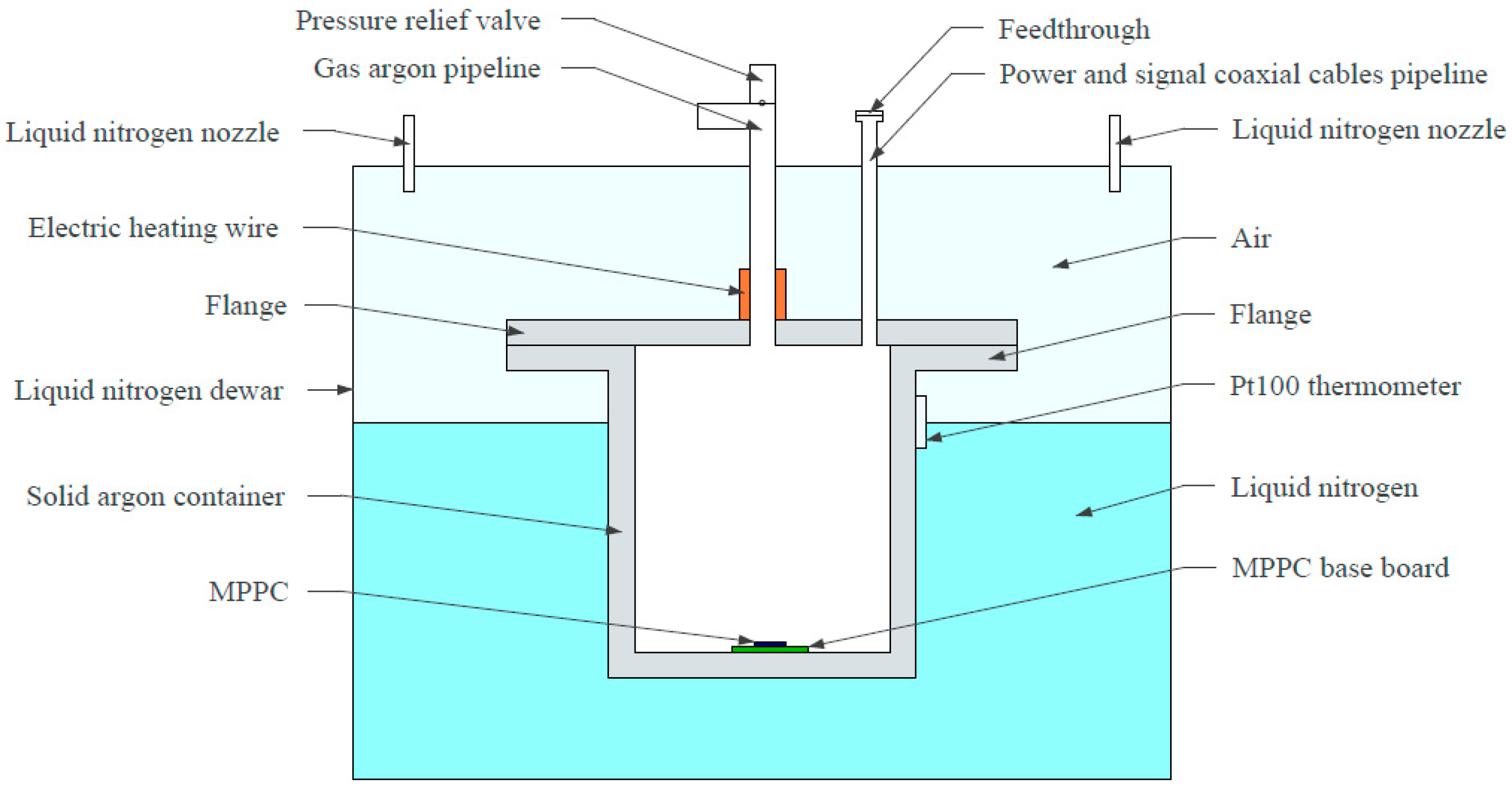
This section introduces the preparing device and procedure of solid argon in the present work. A schematic diagram of the device which successfully prepared the large volume transparent solid argon crystals is shown in
Figure 2. The main component of the device is the stainless steel liquid nitrogen dewar. The dewar contains liquid nitrogen and a stainless steel solid argon container made up of a flange and a cylinder. The liquid nitrogen nozzles outside the solid argon container are on the top of the dewar. The stainless steel gas argon pipeline is fed through the top of the dewar. This pipeline joins the solid argon container to the external argon source with a pressure regulator. The liquid nitrogen sprays from the top to the bottom of the dewar, then it slowly accumulates and eventually submerges the solid argon container; it acts as a cold source freezing the solid argon. The solid argon container is immersed in liquid nitrogen, exchanging heat with liquid nitrogen. The argon in the solid argon container and gas argon pipeline are completely isolated from the nitrogen in the dewar. There is only a heat exchange between the argon and liquid nitrogen in the entire device. The liquid nitrogen dewar is not sealed off and insulated from the external environment to avoid the pressure increase in the dewar due to liquid nitrogen evaporation.
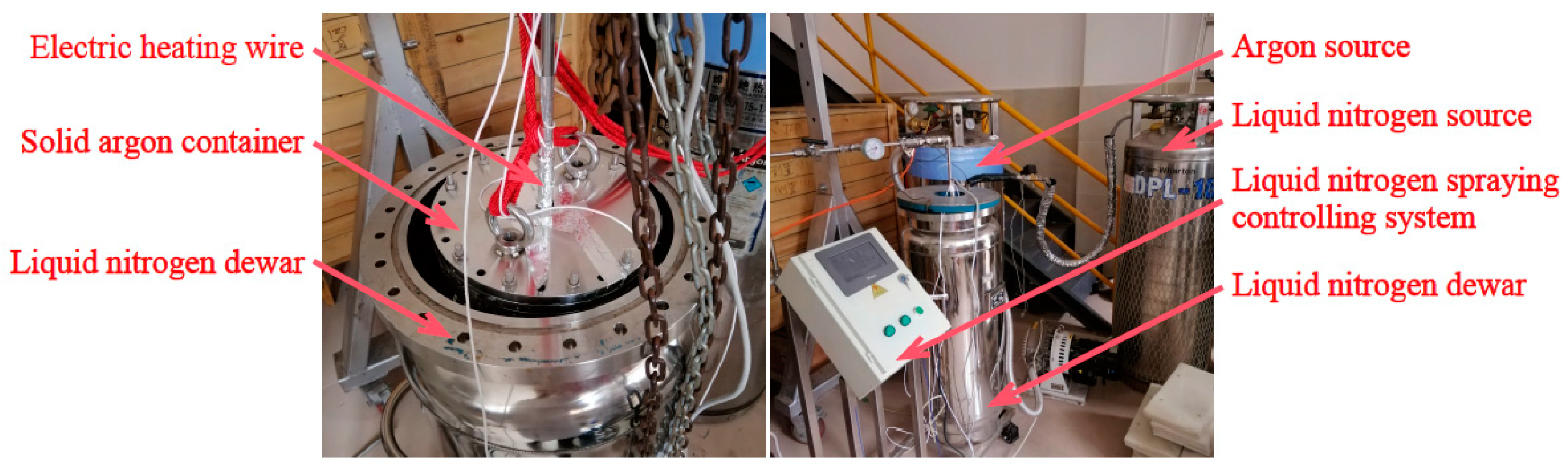
A Pt100 thermometer is put on a suitable position (depending on the volume of solid argon) of the solid argon container to measure the temperature. This temperature is the input parameter for the liquid nitrogen spraying controlling system which is located outside of the dewar (the liquid nitrogen spraying controlling system is not shown in
Figure 2 but shown in
Figure 3). The spraying controlling system could precisely control the amount of liquid nitrogen. The photographs of the solid argon preparation device are shown in
Figure 3.
The solid argon preparation process includes the following steps. First, open the pressure regulating valve of the argon source to make the argon go into the solid argon container and replace the air in it several times. Next, set the cooling procedure for the liquid nitrogen spraying and open the liquid nitrogen pipeline after the argon pressure is fixed so that the liquid nitrogen can spray into the bottom of the dewar under the control of a preset procedure and at a fixed argon gas pressure.
The preset cooling down procedure is a PID control algorithm. The temperature given by the Pt100 thermometer is related to its location (determined by the solid argon volume), and the temperature changes differently at a different location. The function of the Pt100 thermometer is used to indicate and control the liquid nitrogen level. When the liquid nitrogen level is below the Pt100 thermometer, the liquid nitrogen sprays slowly and then the temperature of the Pt100 thermometer drops slowly; when the liquid nitrogen reaches the height of the Pt100 thermometer, the liquid nitrogen level is kept stabilized. We generally set the liquid nitrogen supply as slow as possible and the cooling down rate of about 0.1 °C/min of the Pt100 thermometer is usually proper in the preparation of a large volume (φ = 200 mm × h = 170 mm) solid argon, making the solid argon container cool down slowly and the argon pressure be kept constant easily.
The liquid nitrogen which remains after the evaporation slowly accumulates in the dewar until it reaches the level of the Pt100 thermometer and stays on that level, cooling down the solid argon container. Meanwhile, the gas argon is cooled and condensed into the liquid phase, then, it freezes into the solid phase from the bottom and the walls of the solid argon container. After that, the solid argon crystal gradually grows to the interior and upper part until it fills the whole space inside the container.
Liquid nitrogen serves as a cryostat to prepare the solid argon, so the temperature of the solid argon is the temperature of liquid nitrogen, around −196 °C (the thermometer usually displays −196.0 °C~−196.4 °C). In preparation, firstly, the total amount of liquid nitrogen should be guaranteed to be sufficient. Secondly, the final level of the liquid nitrogen should be kept stable, which is realized through the Pt100 thermometer and the liquid nitrogen controlling spraying system. When the displayed temperature of the Pt100 thermometer is 0.2 °C higher than −196.0 °C, the nitrogen supplementation is turned on to stabilize the liquid nitrogen level. The temperature in this range (−195.8 °C~−196.4 °C) is still below the melting point of solid argon (−189.2 °C), so the state of solid argon remains unchanged.
The cool down time of solid argon depends on its volume. In preparation, the solid argon cool down time varies very widely for different solid argon volumes. For a small volume (φ = 45 mm × h = 220 mm) of solid argon, 6 h can be generally enough, while for a large volume (φ = 200 mm × h = 170 mm) of solid argon, it usually takes more than 36 h to freeze. We judge whether the solid argon has frozen over by reading the argon flow meter; when the reading of the argon flow meter no longer changes, the solid argon has frozen over.
A certain pressure is necessary in the preparation of transparent solid argon. Freezing under a very low pressure is unable to get the transparent solid argon. Based on our tests, the argon gas pressure ranging from 0.02 MPa to 0.2 MPa (both are gauge pressures) ensures the generation of transparent solid argon in the preparation process, though the minimum necessary pressure is not exactly known yet. That pressure range is friendly toward the preparation, so the control accuracy of the argon pressure gauge may not need to be very high. At the cooling down rate of 0.1 °C/min in the preparation of a large volume (φ = 200 mm × h = 170 mm) solid argon, the argon pressure controlling precision can reach ±0.02 Mpa with an instrument accuracy of ±0.002 Mpa, and the flow of argon is under 25 L/min (the maximum flow rate of argon purifier we will install is 30 L/min.) based on our device (the argon flow rate depends on the gas pipeline diameter, gas argon pressure, room temperature, cooling down rate, and the volume of the solid argon container, and will be very different in a different device).
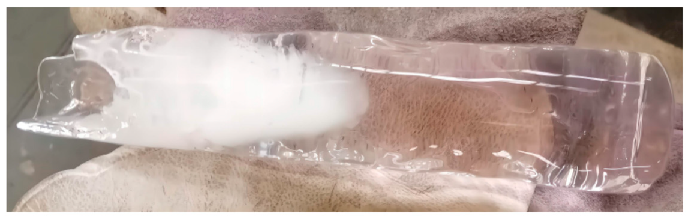
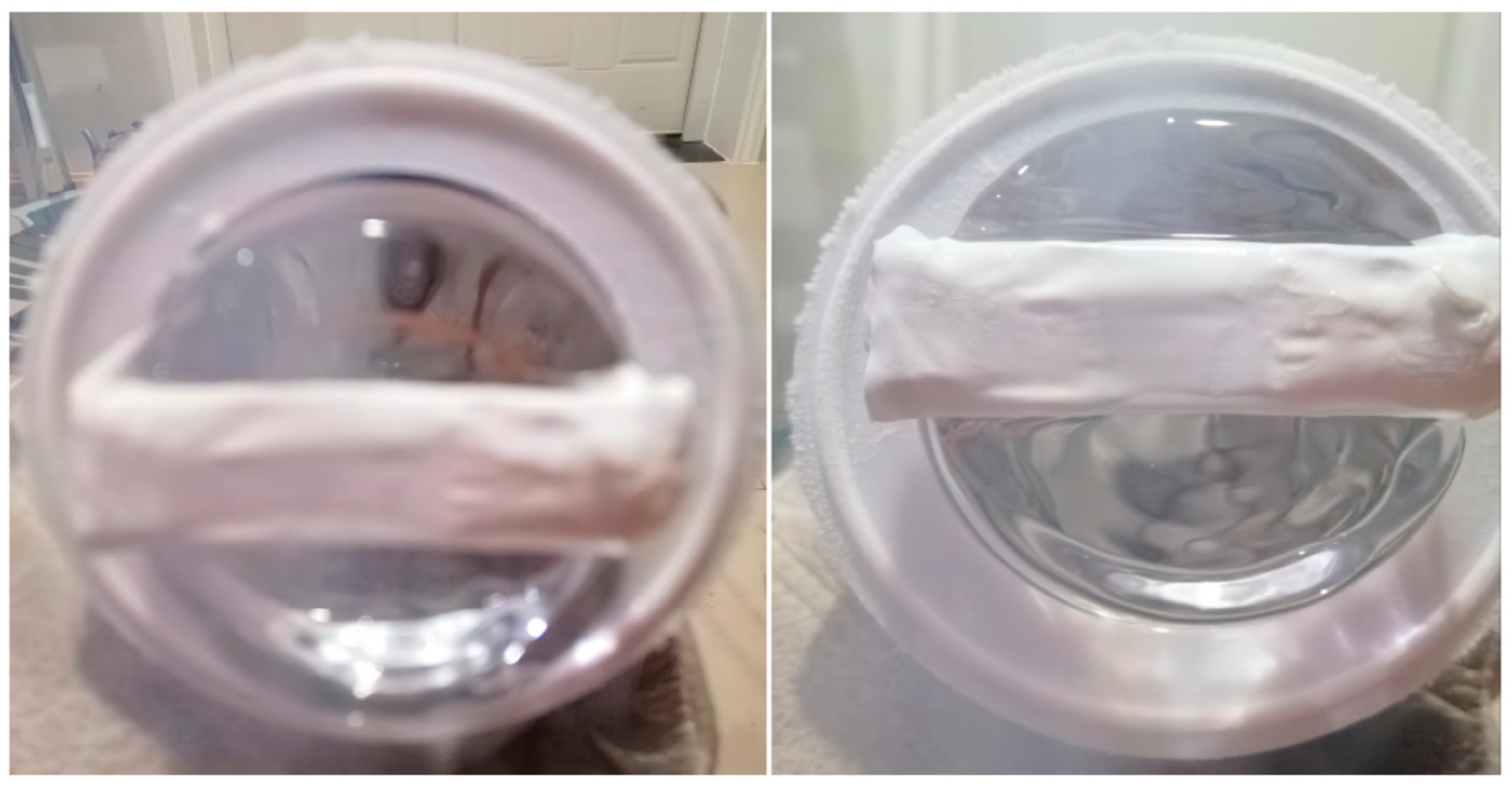
The electric heating wire winds around the joint of the gas argon pipeline and the solid argon container to avoid freezing and blocking the argon pipeline. If the argon inlet is frozen, the pressure in the solid argon container is not enough, resulting in the white opaque solid, as shown in the left part of
Figure 4.
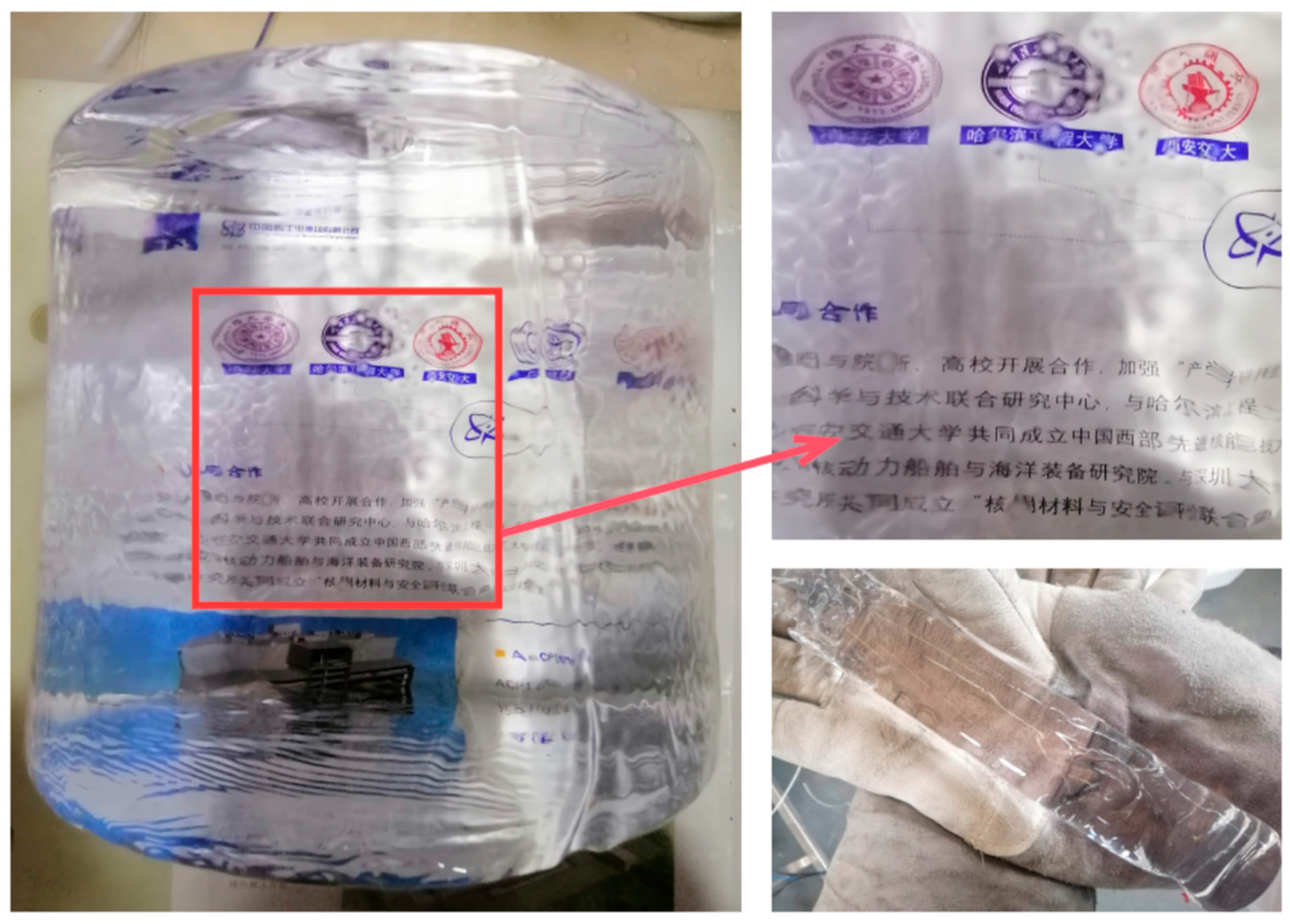
Figure 5 shows the transparent solid argon made in this work. The texts and pictures behind transparent solid argon can be seen clearly in the zoom of
Figure 5.
3. Prototype Solid Argon Scintillation Detector and Its Feasibility Test
In this section, we describe the prototype scintillation detector made by solid argon in the present work. In our prototype scintillation detector, the solid argon container is
φ = 51 mm ×
h = 230 mm with 3 mm Polytetrafluoroethylene (PTFE) covering the solid argon sensitive volume. A low temperature ultraviolet multi-pixel photon counter (MPPC, also known as a silicon photomultiplier-SiPM) of HAMAMATSU S13370-3050CN with an effective area of 3 × 3 mm
2 was used to directly detect the solid argon scintillation light with a 128 nm wavelength.
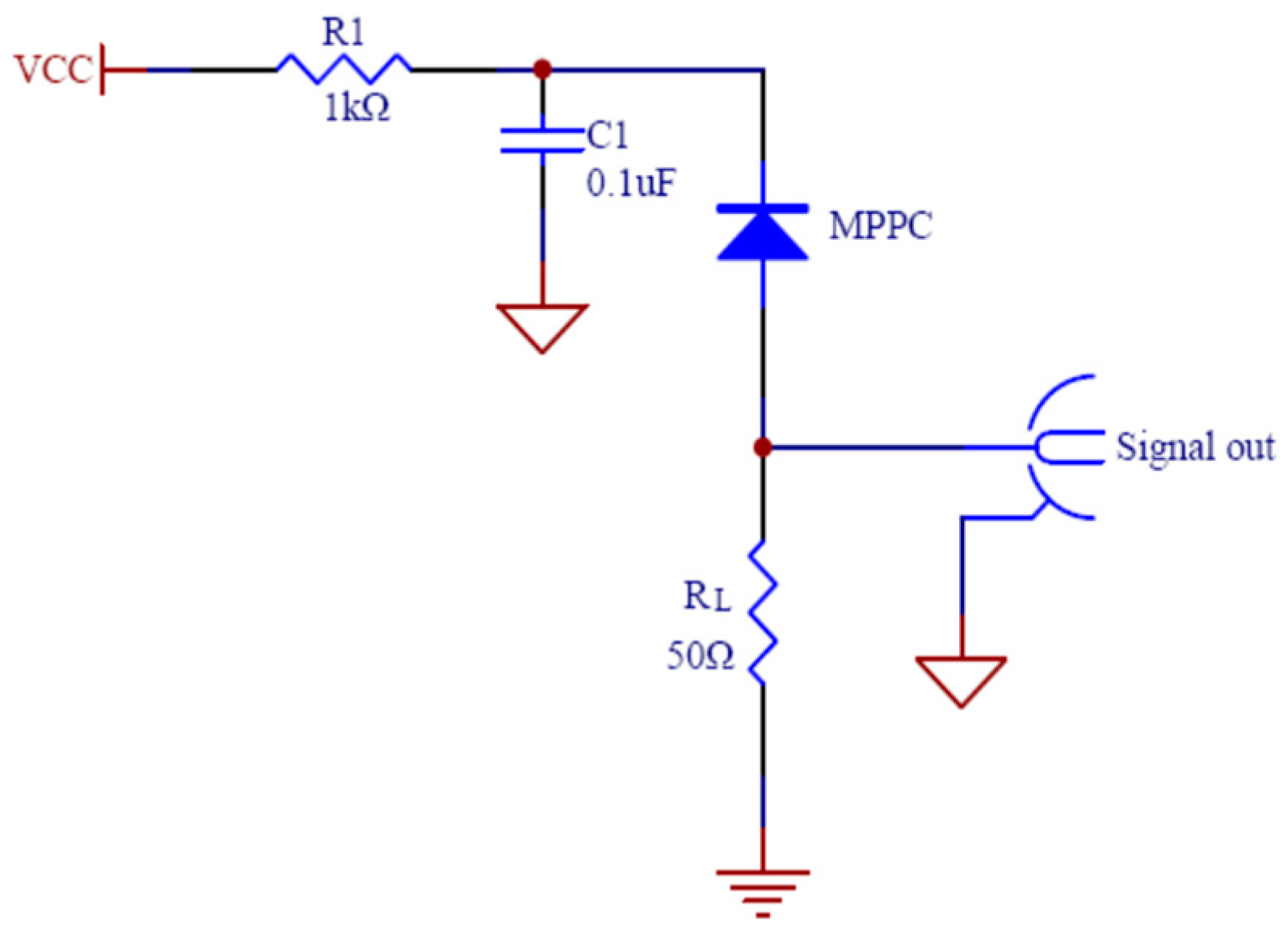
Figure 6 shows the MPPC circuit with a 50 Ω load resistance. The current signal from the MPPC is converted into a voltage signal by the 50 Ω resistor. A preamplifier is arranged outside and very close to the solid argon container by coaxial cable connection. Placing the preamplifier outside of the solid argon container avoids freezing the preamplifier. Besides observing the amplified waveform, disconnecting the preamplifier facilitates the direct observation of the MPPC waveform to check whether the MPPC and preamplifier work properly.
The MPPC connecting the above circuit together works as a photodetector to detect scintillation light. The photodetector surface is coated with white tape to only expose the photosensitive region of the MPPC. In this way, the absorption of scintillation light by the dark color circuit board can be greatly reduced. Solid argon crystal melts quickly at room temperature, so it cannot be operated like a conventional scintillator. The photodetector is placed at the bottom of the solid argon container before the preparation in order to be well coupled to the solid argon crystal to form a scintillation detector.
Figure 7 shows the solid argon crystal coupled to the photodetector which is coated with white tape and includes an MPPC which is embedded in the circuit board. The scintillation light is stimulated by the 662 keV γ ray from
137Cs.
It is tested repeatedly and indicates that solid argon sticks very well with its attachment surface. When the MPPC is located at the bottom of the solid argon container and freezes together with the argon, the prepared solid argon crystal is very tightly coupled to the MPPC without gaps between them. It could be concluded that the MPPC should be already contracted before the solid argon freezes so that the MPPC is very tightly coupled to the solid argon crystal and there are no gaps between them. This is very good for the solid argon scintillation light detection.
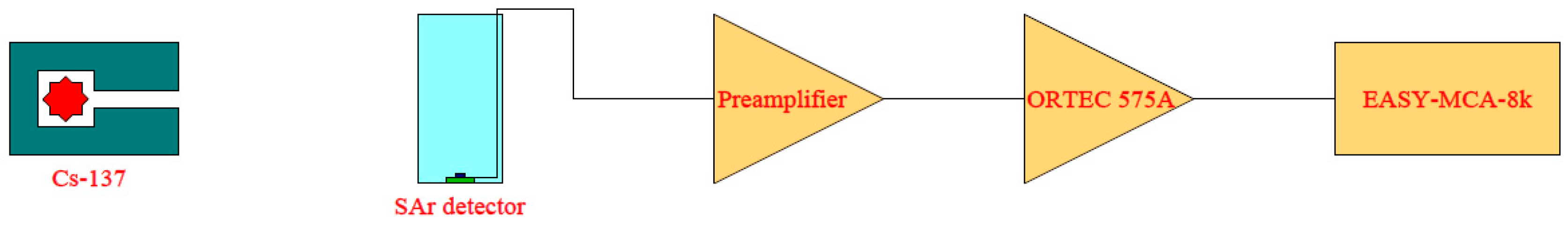
There is no dedicated electrical channel preset in advance in the solid argon trial preparation device. In order to connect the outside DC power supply and oscilloscope, the power and signal coaxial cables of the MPPC are fed along the side wall of the solid argon container and through its top via a feedthrough. The MPPC output signal is amplified by a homemade current-sensitive preamplifier. The amplified signal is fed into the oscilloscope for observation or into the multichannel analyzer ORTEC EASY-MCA-8k by an ORTEC 575A amplifier to obtain the pulse amplitude spectrum. The block diagram of the spectrum acquisition system is shown in
Figure 8, schematically.
4. Results and Discussions
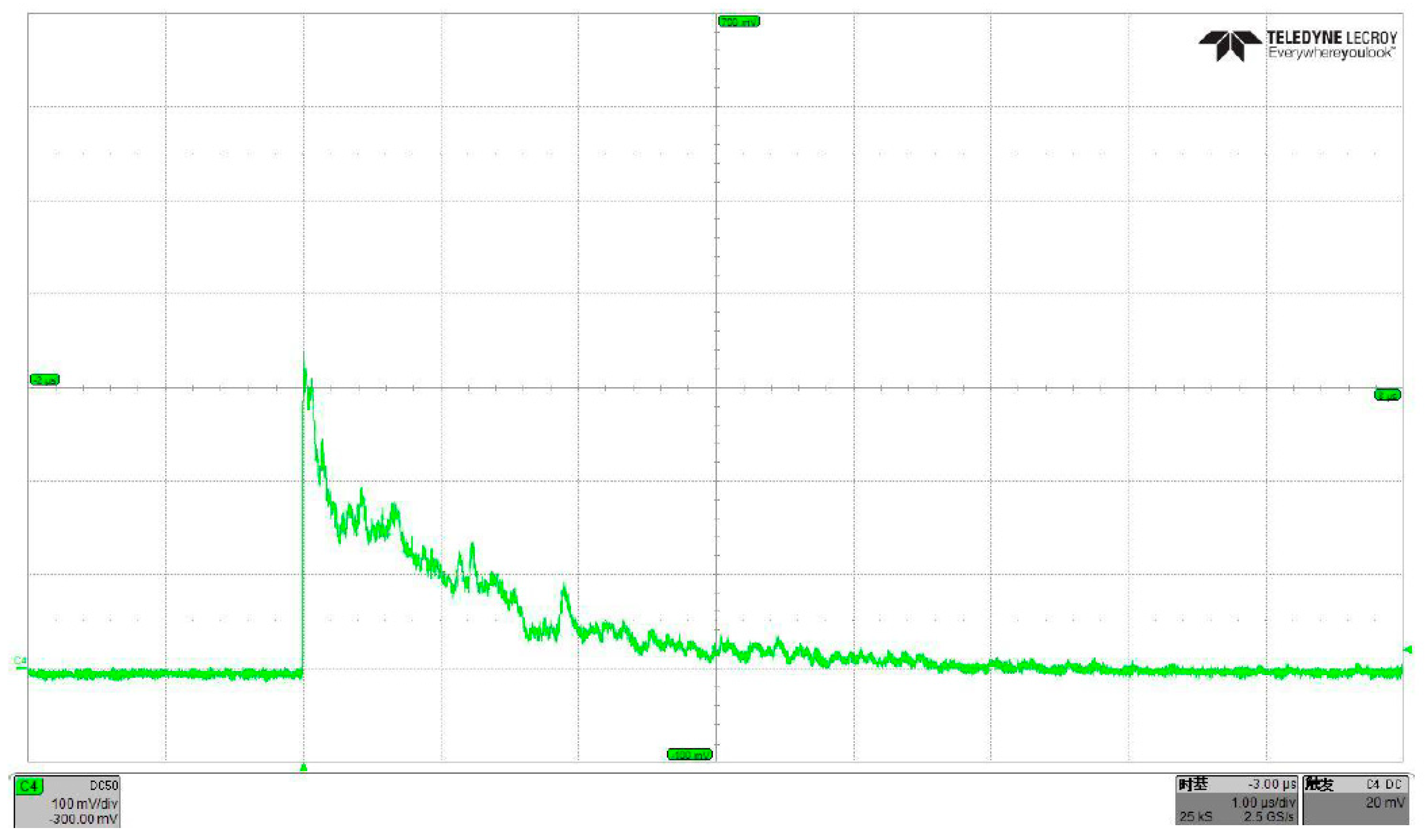
This section presents the signal and pulse amplitude spectrum obtained by our solid argon detector. A sampled scintillation signal amplified by a current-sensitive preamplifier from solid argon stimulated by 662 keV γ rays is shown in
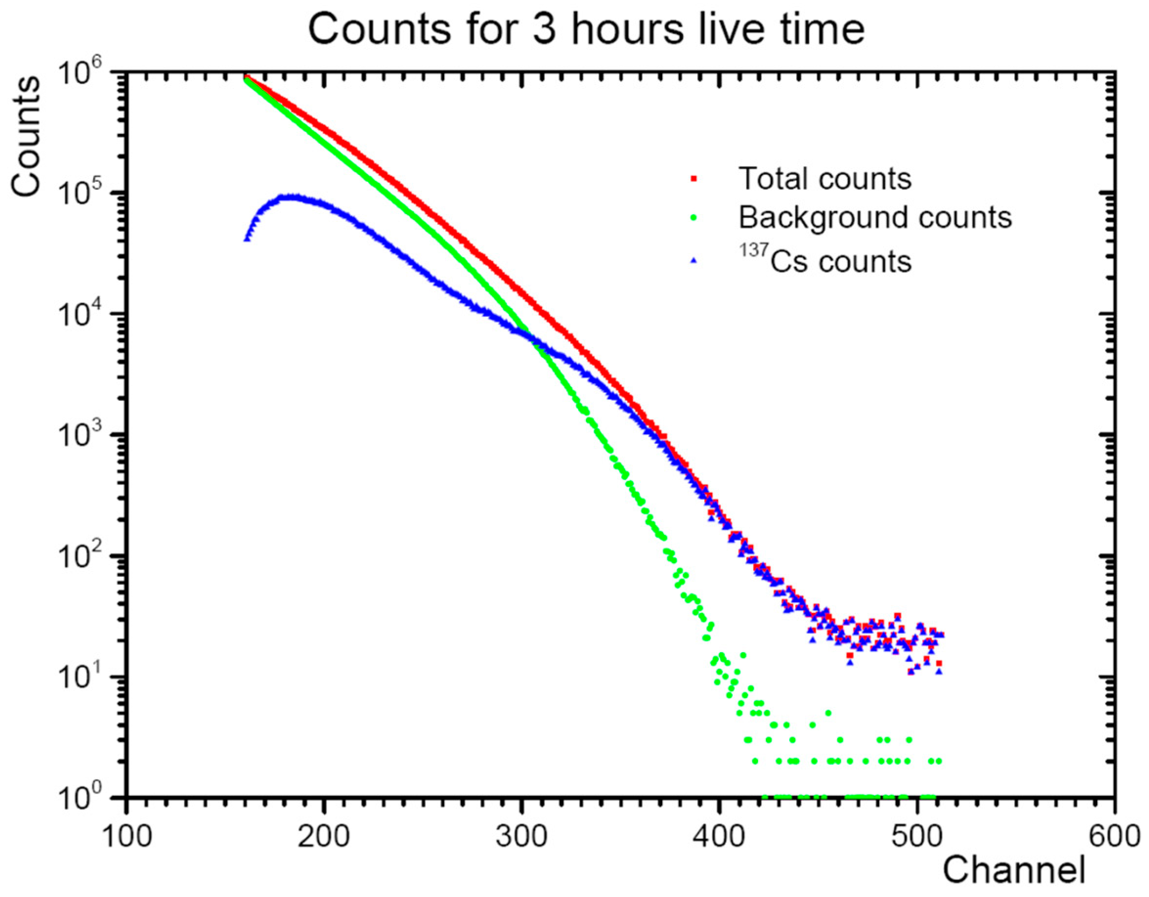
Figure 9. It is sampled by a TELEDYNE LECROY HDO4054 oscilloscope with a 500 MHz analog bandwidth, 2.5 GS/s sampling rate, and a 13-bit vertical resolution. When the γ ray source is turned off, the count rate of the pulse signals displayed on the oscilloscope is low. On the other hand, when the γ ray source radiates, the oscilloscope displays pulse signals with a high count rate. The pulse amplitude spectra of MPPCs signals from the solid argon detector recorded by the multi-channel analyzer for three hours of live time, is shown in
Figure 10. The difference between the total counts and the background counts (when γ ray source is turned off) in the pulse amplitude spectra is obvious. The very different pulse count rates and the pulse amplitude spectra when the γ ray source is turned on or off demonstrates the stable operation of our solid argon prototype detector.
A large number of signals like those shown in
Figure 9 and the pulse amplitude spectra in
Figure 10 suggest that it is feasible to use solid argon as a scintillator. Intensive studies have been done by R. Acciarri et al. on the scintillation properties of liquid argon at various levels of contamination [
20,
37,
42]. All the emission bands of argon in the liquid phase are attributed to the decay of excimer-like molecular centers Ar
2* from the lowest excited bonding molecular states
1Σ
u+ (0
u+) and
3Σ
u+ (1
u) to the ground state
1Σ
g+ (0
g+) [
32]. There is a general agreement that the d band (assigned to the broad prominent Gaussian bands due to the emission from a vibrationally relaxed diatomic Ar
2* homonuclear molecule) in solid argon is due to the radiative decay of the lowest vibrational level of the 0
u−, 1
u (
3Σ
u+), and 0
u+ (
1Σ
u+) branches of the molecular centers [
32]. The efficient trapping of excitons is caused by the two-center localization mechanism in solid argon, and 99% of the excitations results in the formation of diatomic excimers [
32]. In solid argon, the relative intensities of the weak emissions (bands a, b, and c) are 10
−2 to 10
−3 of the major two-center molecular emission band (band d) [
32]. For argon, the emission bands in the three phases are almost identical [
32]. Some studies suggest that the scintillation decays of solid argon and liquid argon are similar [
19]. According to the fluorescence mechanism of solid argon described in reference [
32], it can be concluded that the scintillation photon energy in the major band (d band) is lower than the atomic argon first excited state, just like that in the liquid argon, so the solid argon is transparent to its scintillation light.
Therefore, similar fluorescence properties of the solid argon can be predicted by analyzing and comparing to those of the liquid argon at different degrees of contaminations. The amplitude spectrum of
137Cs γ rays obtained from our prototype solid argon detector is consistent with the results of liquid argon with high impurity contamination in references [
20,
42].
From
Figure 10, the measured pulse amplitude (proportional to energy) spectrum of the
137Cs γ rays clearly shows the Compton continuum with a high count rate in the low energy zone. This is consistent with the energy spectrum characteristics when small size scintillators measure high energy γ rays. First, the atomic number of argon is too low to have a notable photoelectric cross section for 662 keV. The pulse amplitude spectrum of the
137Cs γ rays in
Figure 10 is basically contributed by Compton scattering. Second, the diameter of the solid argon detector in the first test is 45 mm, indicating that in this thin crystal it is almost impossible to deposit the full photon energy through multiple Compton scatterings, hence it is difficult to completely deposit the full energy of 662 keV in the solid argon crystal. Therefore, the measured pulse amplitude spectrum of
137Cs γ rays in
Figure 10 mainly shows the Compton continuum with a high count rate in the low energy zone, but no full energy peak of 662 keV. This spectrum is validated by the large number of signals with a low amplitude (larger than the dark count amplitude of MPPC) and a fast rise edge displayed on the oscilloscope when the scintillation light signal waveforms are observed. If the crystal size is increased, the photon energy of 662 keV can be fully contained. The gas argon we adopted has about a 100 ppm impurity concentration detected by the chromatograph due to a large amount of contamination such as N
2, O
2, H
2O, and CO
2, resulting in scintillation light quenching and absorption [
20,
42]. After this feasibility test, we will focus on the increase in light yield and the decrease in light attenuation for the solid argon crystal, namely the increase in argon purity. A much larger optimized solid argon container and pipelines will be processed according to the requirements of high-purity argon gas. As a significant consequence, we expect to obtain an increase of the scintillation light and a decrease of the light attenuation of the solid argon crystal.
Although the contamination negatively affects the performance of the detector, it has little influence on the solid argon detector feasibility test. The backgrounds in solid argon detector generally originate from the decay of radioactive impurities in solid argon and its surrounding materials, and the cosmic rays. As described above, if the detector is made with low background materials and is placed in an underground laboratory, the background can be much lower. We will further lower the background of the solid argon detector to meet the requirements of the future experiment of CDEX. When the background of the solid argon detector is successfully lowered, we will combine the HPGe detectors array and the solid argon veto detector to the detector system in the China Jinping Underground Laboratory (CJPL). We will also do experiments to directly compare our solid argon with the same size liquid argon veto detector to verify the superior ability of solid argon veto detector in depressing backgrounds.
The successful preparation of solid argon and its feasibility test as a scintillator indicate that building a particle detector by using our transparent solid argon crystal is practical and effective.
5. Summary and Prospect
Based on our approach, the large volume transparent solid argon crystal has been successfully prepared, as shown in
Figure 5. A prototype detector is made directly using our transparent solid argon preparation device and the crystal generated in it. The scintillation signal and pulse amplitude spectrum are successfully obtained. The Compton continuum is clearly presented in the pulse amplitude spectrum. These measurements show that a particle detector using transparent solid argon crystal is practical and effective. The preparation of solid argon and its feasibility test as a scintillator in this work gives another hint that solid argon would become a promising scintillation material in future particle detection experiments, especially in the CDEX-300.
However, this work is still a preliminary study of a solid argon detector. The current prototype detector in this work needs to be upgraded and reinforced to meet the demands of the active shielding (veto) scintillation detector used in future CDEX experiments. Next, we will focus on improving the purity of argon. An advanced rare gas purifier will be installed in the present device in order to prepare a large volume solid argon crystal made of high-purity argon. The acquisition of high-purity argon is extremely helpful for low-background detector studies. In addition, the various properties of solid argon crystal as a scintillator, such as n/γ discrimination, fluorescence attenuation time, fluorescence attenuation length, light yield, and the comparison with those corresponding properties of liquid argon will be explored. The experimental prospect and layout of a solid argon scintillation detector which could be used as a veto detector in 1725 m3 liquid nitrogen in CDEX-300 is being analyzed. The results would be presented in a forthcoming study.
In summary, this work proves that the cryogenic scintillation detector with solid argon proposed in our study is completely feasible. The solid argon has great potential to become the desirable scintillation material to be applied in low background particle physics experiments in the future, including the dark matter detection, the search for the neutrinoless double-β decay, and the neutrino physics experiment.

 ,
, 


