
Comparative Study of the Sensitivity of PLA, ABS, PEEK, and PETG’s Mechanical Properties to FDM Printing Process Parameters


Abstract
:1. Introduction
2. Printing Process Parameters
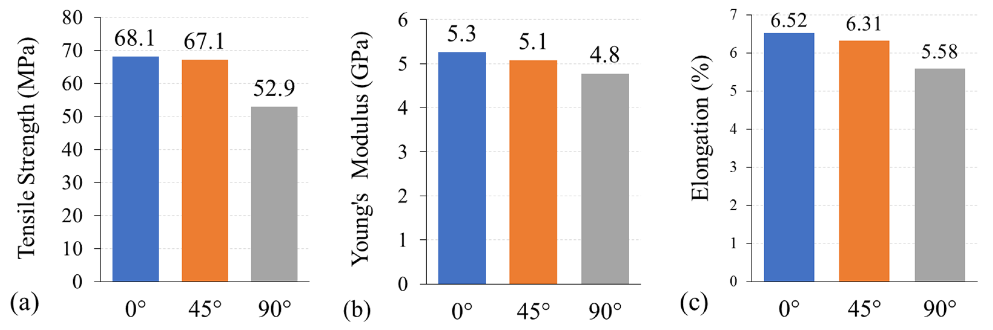
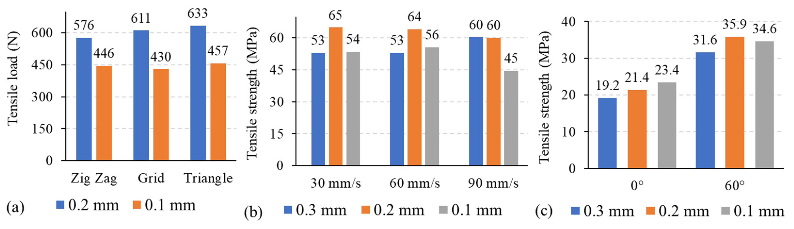
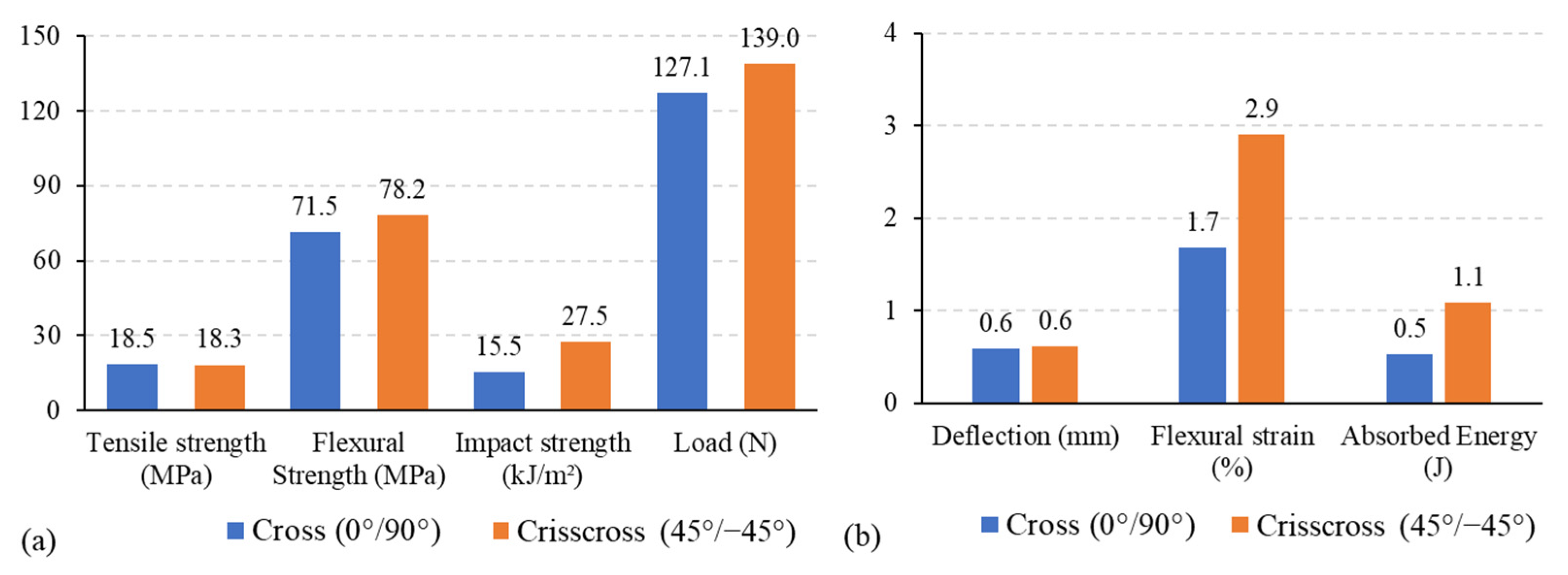
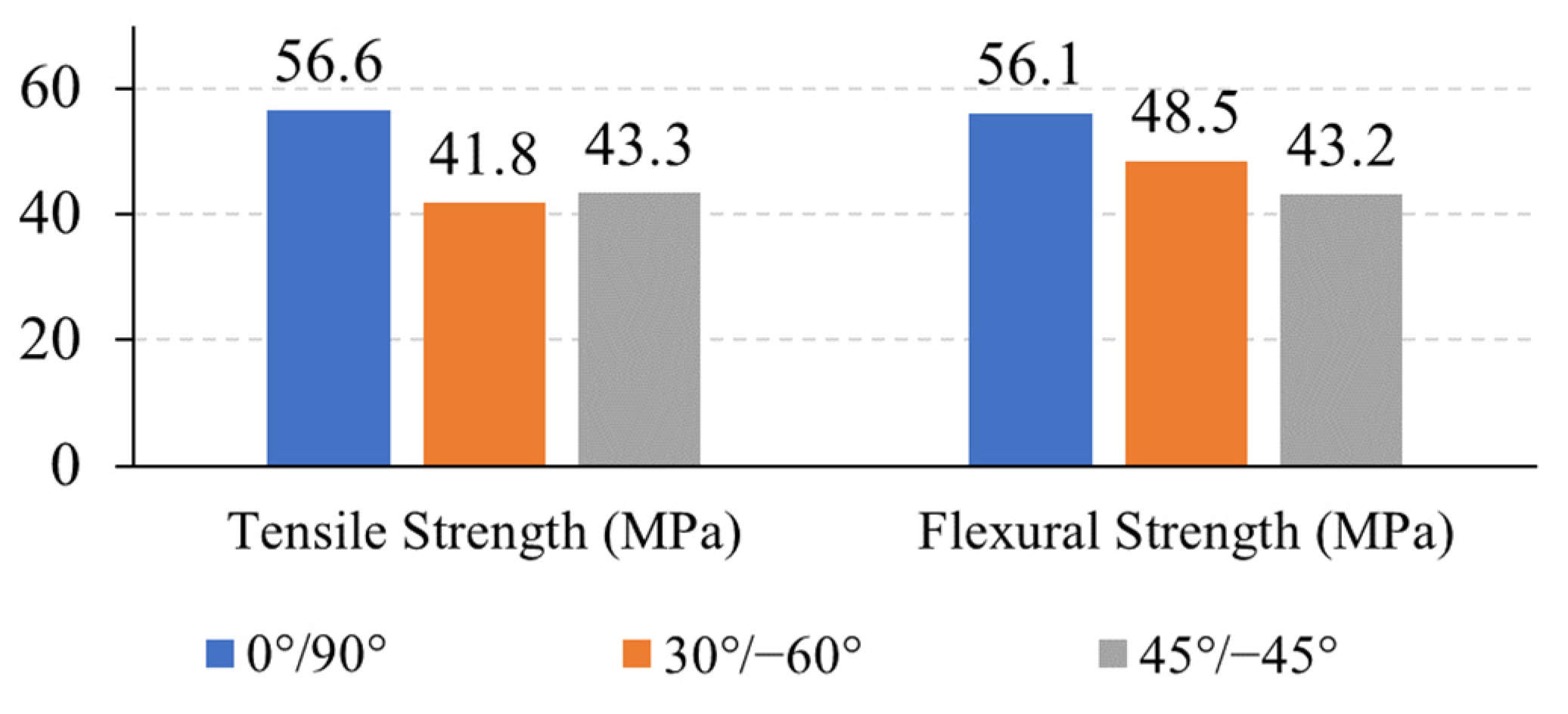
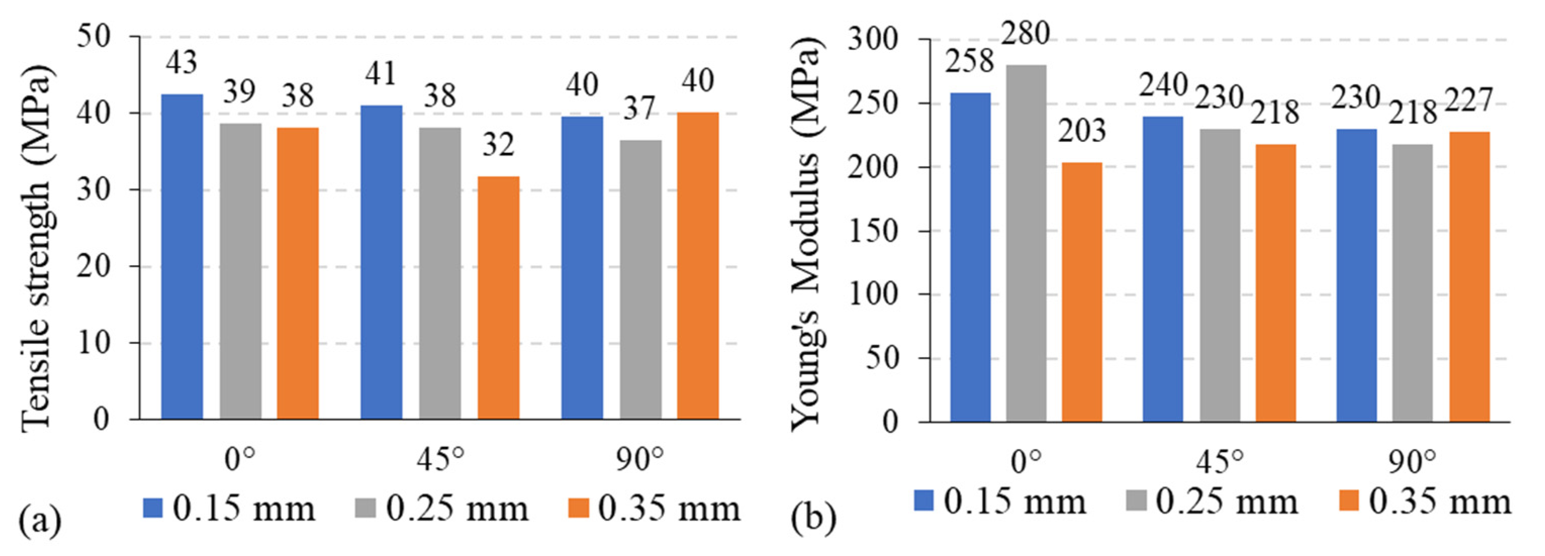
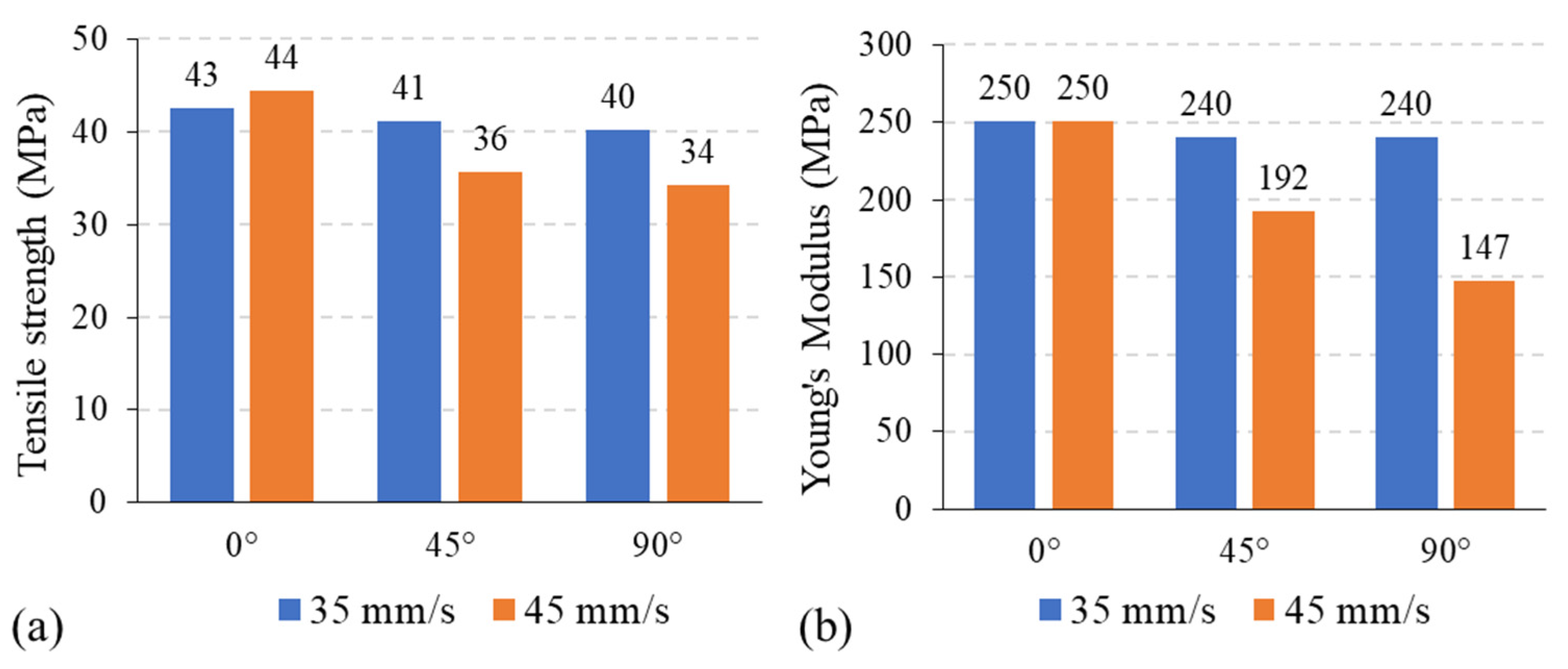
- Raster angle, sometimes called raster orientation, is the direction of the deposited layers with respect to the build platform. It usually ranges from 0° to 90°. The deposited filaments exiting the 3D printer nozzle form rasters (extrusions) that can be constructed using various angles to fill the interior of the part being manufactured. Raster angle is an essential parameter for the FDM process as it influences the anisotropy of the parts [18,68]. Results reported in the literature illustrate that the raster angle significantly affects the mechanical properties of all materials to different extents. Generally, the tensile strength becomes higher once the raster direction is the same as the loading direction due to high anisotropy.
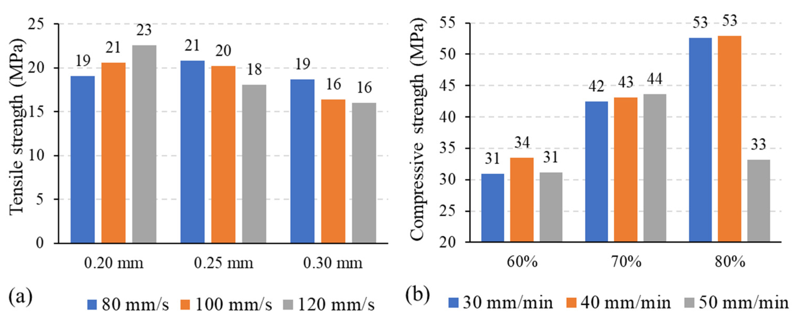
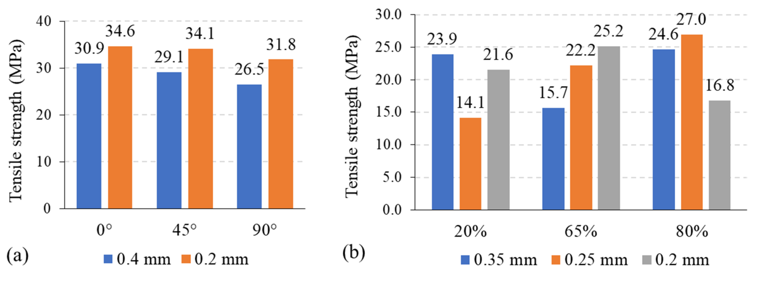
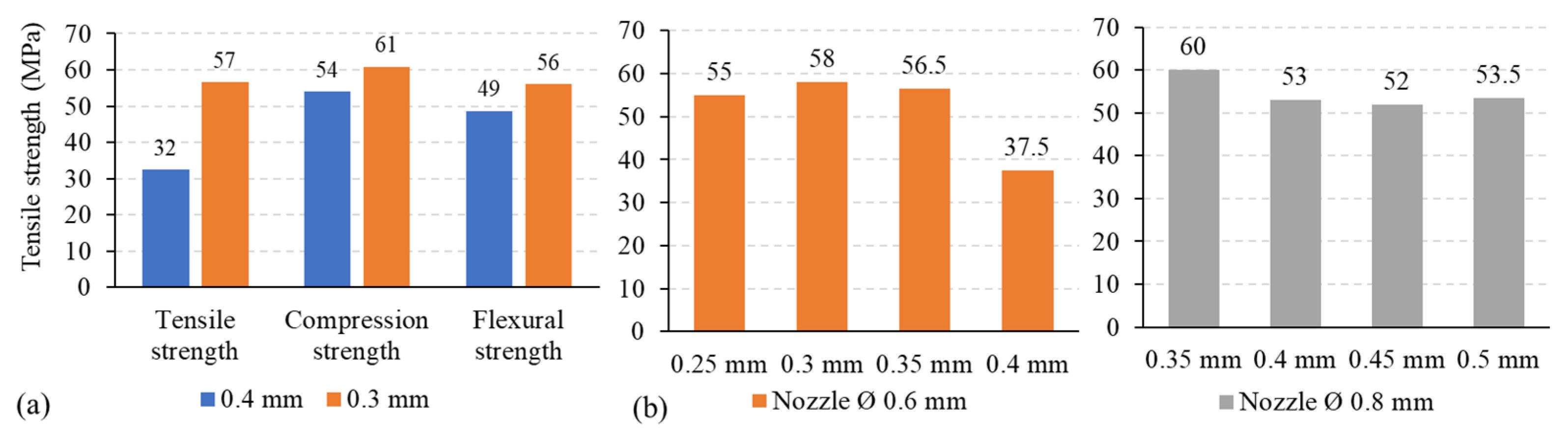
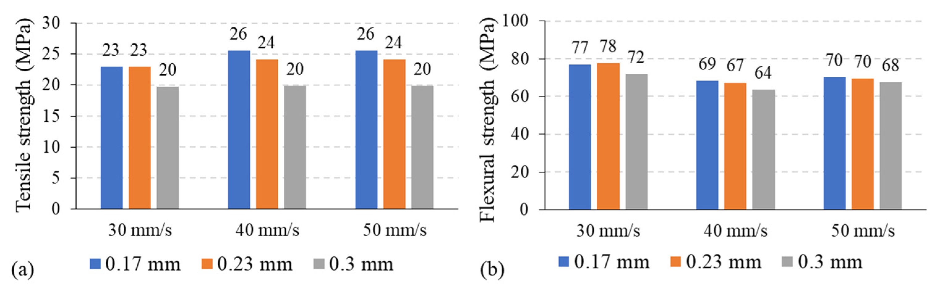
- Layer thickness is the height of each deposited layer in the 3D printed product. A product’s height is the sum of the thicknesses of the stacked layers extruded from the nozzle tip. It depends on the nozzle tip diameter and the filament material. Usually, it ranges from 0.07 to 0.4 mm. The effect of layer thickness on strength and other mechanical properties is considerable. Generally, the experimental results show that flexural, tensile, and compression strength increase as layer thickness decreases, which leads to products being made of a greater number of layers. Consequently, increasing the layer number leads to increasing the process of reheating previous layers, which improves layer-to-layer diffusion. Also, the surface quality of the printed objects increases as layer thickness decreases [69].
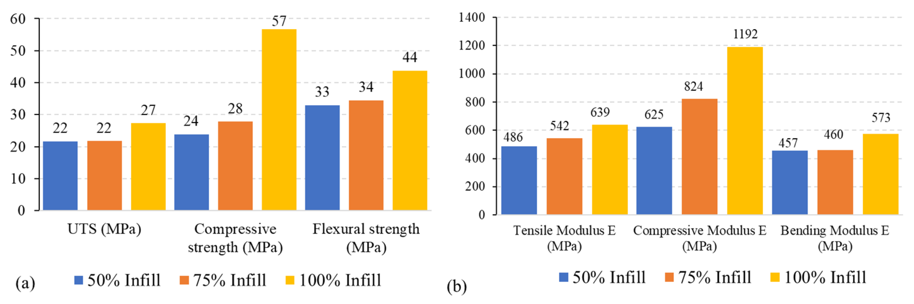
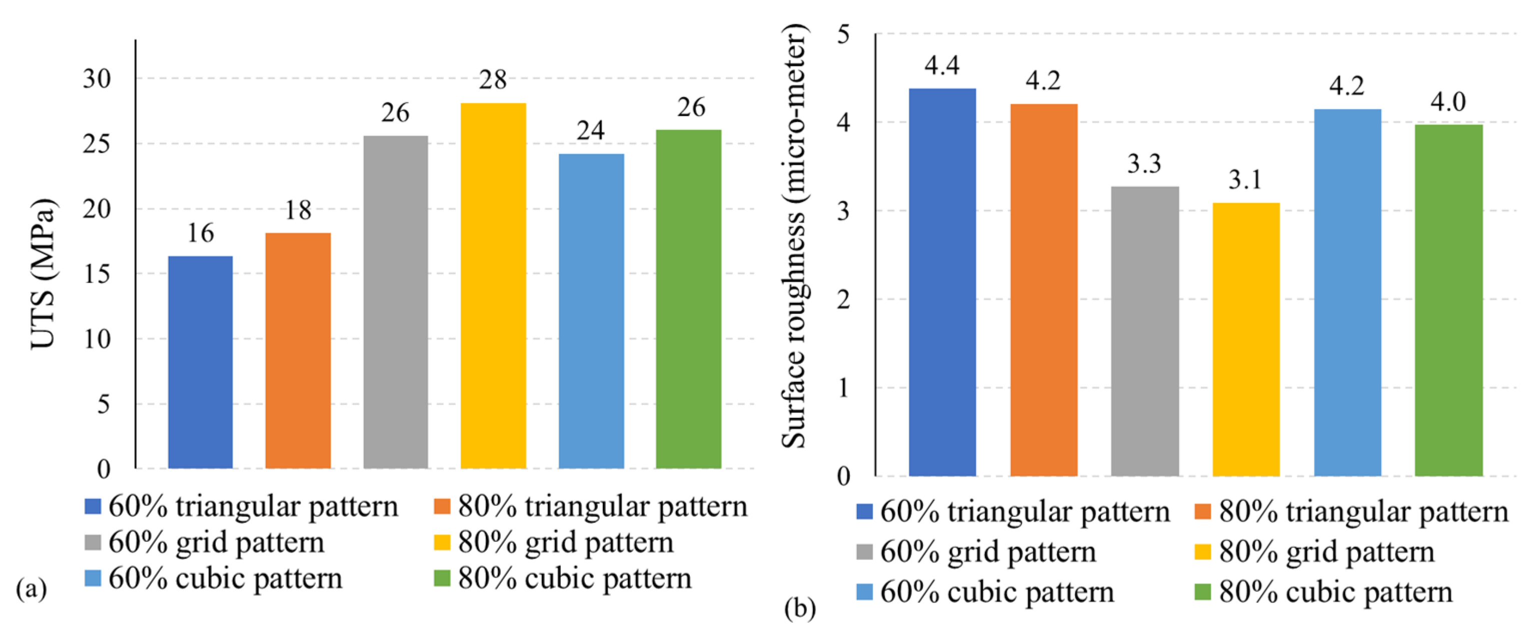
- Infill percentage, sometimes called infill density, describes the solidity of the invisible inner structure of a printed part. In other words, it describes the infill volume, which plays a major role in a printed part’s strength and mass. Usually, it ranges between 20% and 100%. Infill percentage is considered one of the leading parameters that significantly affect the part’s mechanical properties [70]. For instance, the infill percentage determines the contact zone between the filament rasters and layers, which affects mechanical properties [14,71]. Studies show that infill percentage has a significant influence on mechanical properties. Their results indicate that mechanical properties improve as the infill percentage increases since the resistant section (transverse to the load) is smaller with lower infill percentages.
- Printing speed is the nozzle’s horizontal speed on the build platform during extrusion and deposition. It determines the total printing time. It depends on the printing technique (stereolithography (SLA), selective laser sintering (SLS), and FDM) and the filament material used. Typically, it ranges from 15 to 90 mm/s. The printing speed influences the material’s spread and forming dimension more than all other FDM process parameters. High printing speeds result in over-extrusion on part edges and reduces extrusion width which leads to poor dimensional accuracy as additional layers are added before previous layers have completely solidified.
- Extrusion temperature is defined as the heating temperature for a filament material in the nozzle section during the extrusion process. It varies depending on the thermoplastic material type and the printing speed. Extrusion temperature ranges are illustrated in Table 1.
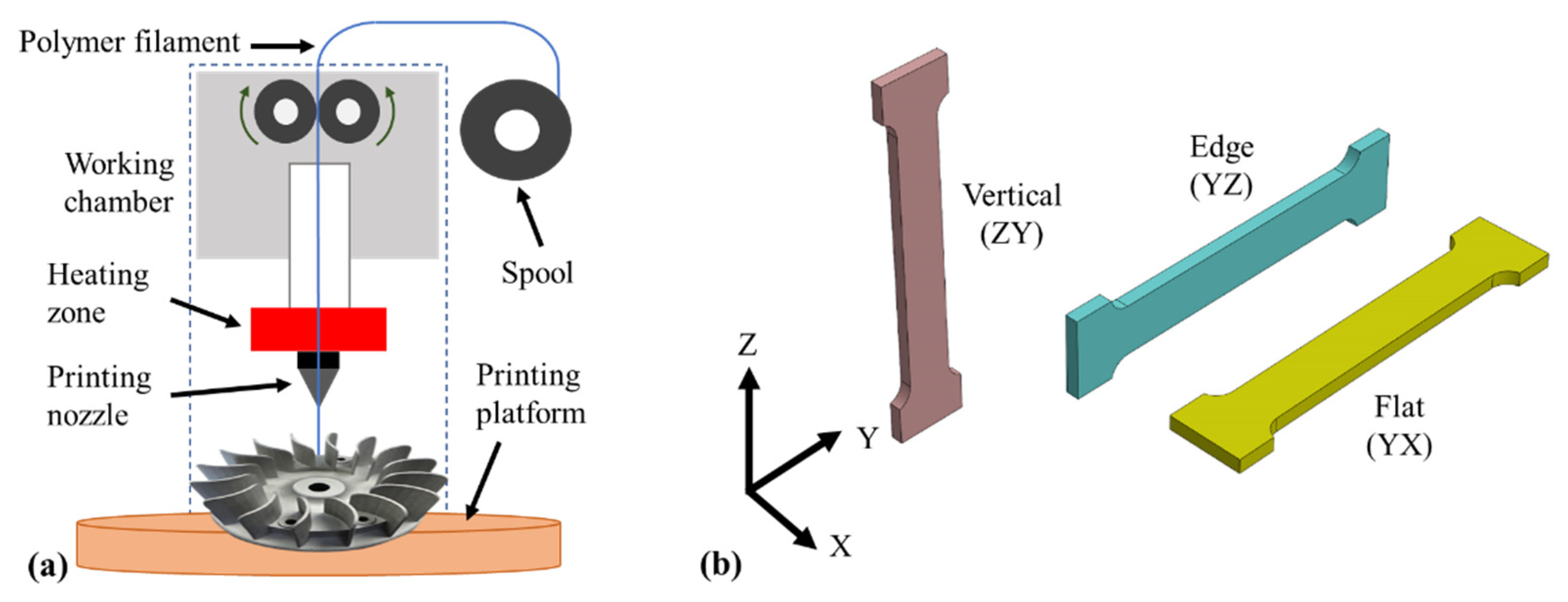
- Build orientation is defined as the posture/orientation of an object with respect to the Cartesian coordinate system directions while printing. Usually, the vertical posture is the ZY-plane, the edge posture is the YZ-plane, and the flat posture is the YX-plane as presented in Figure 1b.
- The air gap is the gap between rasters on the same layer of a printed part. It usually ranges from 0 to 0.08 mm. However, the air gap can also be negative (superposition of adjacent depositions) in 100% infill. The effects of air gap on mechanical properties of PLA parts can be low [72], while it can be relevant in ABS parts [73]. A negative air gap increases both strength and stiffness.
- Raster width is the width of a single deposited raster and depends on the extrusion nozzle diameter, printing speed, and the ratio between printing speed and extrusion speed, which is called “extrusion multiplier” [74]. The calibration of this parameter is very important for part accuracy and mechanical properties. Usually, it ranges between 0.1 and 0.7 mm.
- Contour is the outer solid layer that encloses the printed part’s inner infill structure. It corresponds to the number of solid outer layers. Usually, it ranges from 1 to 6 contours.
3. Polylactic Acid (PLA)
3.1. Influence of Raster Angle
3.2. Influence of Layer Thickness
3.3. Influence of Infill Percentage
3.4. Influence of Printing Speed
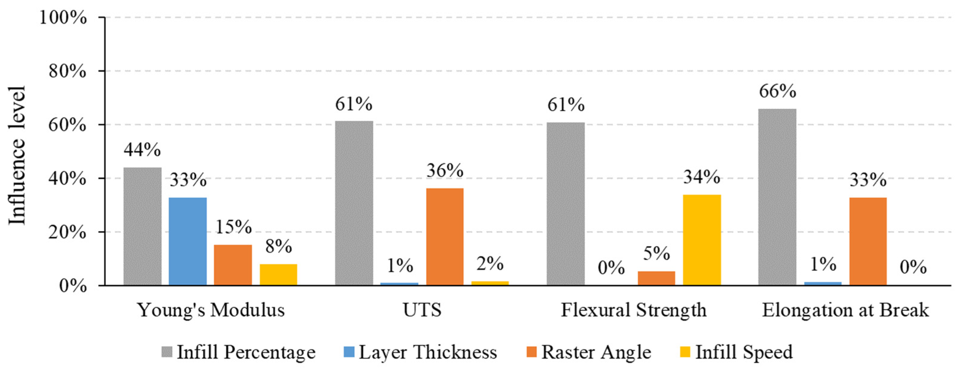
3.5. PLA Mechanical Properties Sensitivity Study Using ANOVA
4. Acrylonitrile Butadiene Styrene (ABS)
4.1. Influence of Raster Angle
4.2. Influence of Layer Thickness
4.3. Influence of Infill Percentage
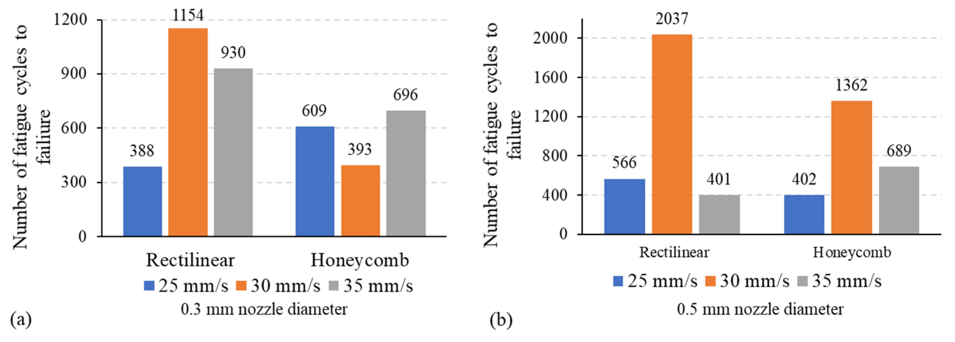
4.4. Influence of Printing Speed
4.5. ABS Mechanical Properties Sensitivity Study Using ANOVA
5. Polyether Ether Ketone (PEEK)
5.1. Influence of Raster Angle
5.2. Influence of Layer Thickness
5.3. Influence of Infill Percentage
5.4. Influence of Printing Speed
5.5. PEEK Mechanical Properties Sensitivity Study Using ANOVA
6. Polyethylene Terephthalate Glycol (PETG)
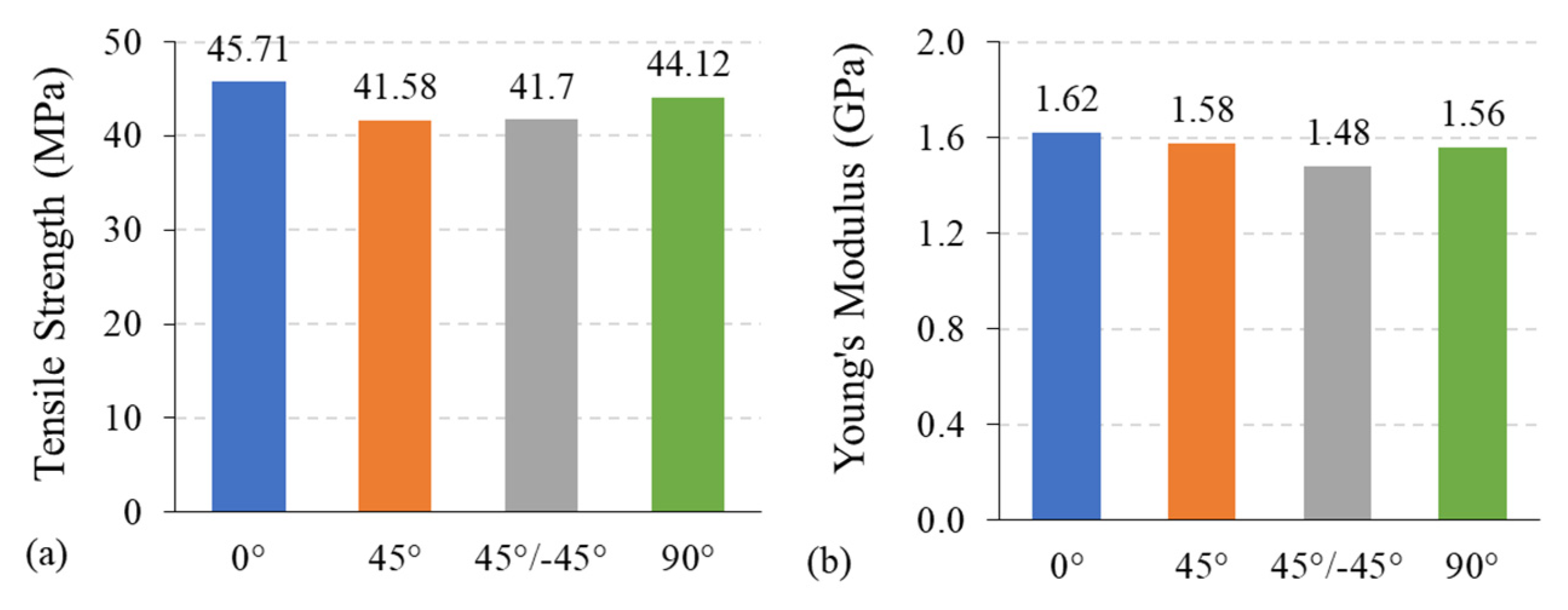
6.1. Influence of Raster Angle
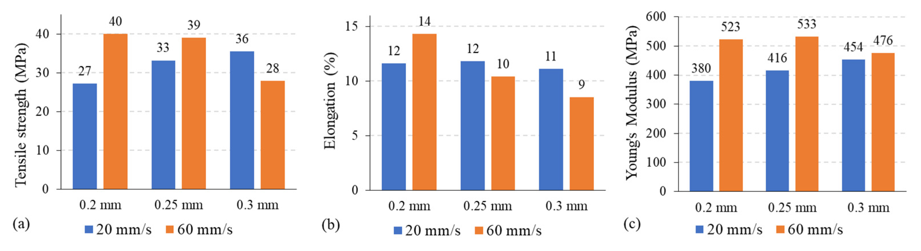
6.2. Influence of Layer Thickness
6.3. Influence of Infill Percentage
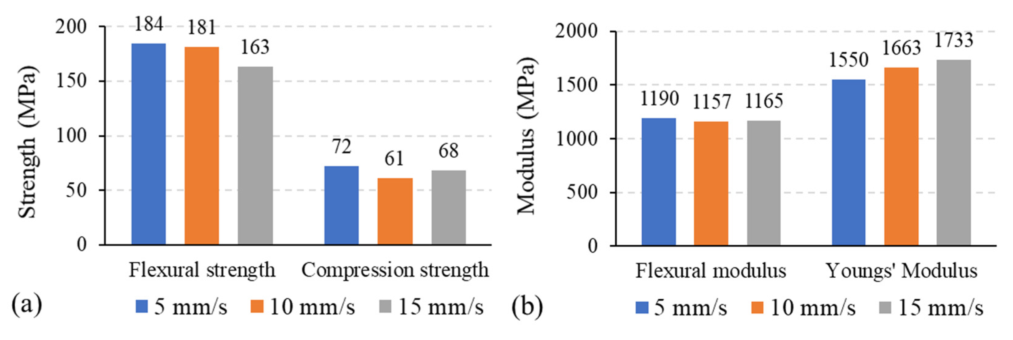
6.4. Influence of Printing Speed
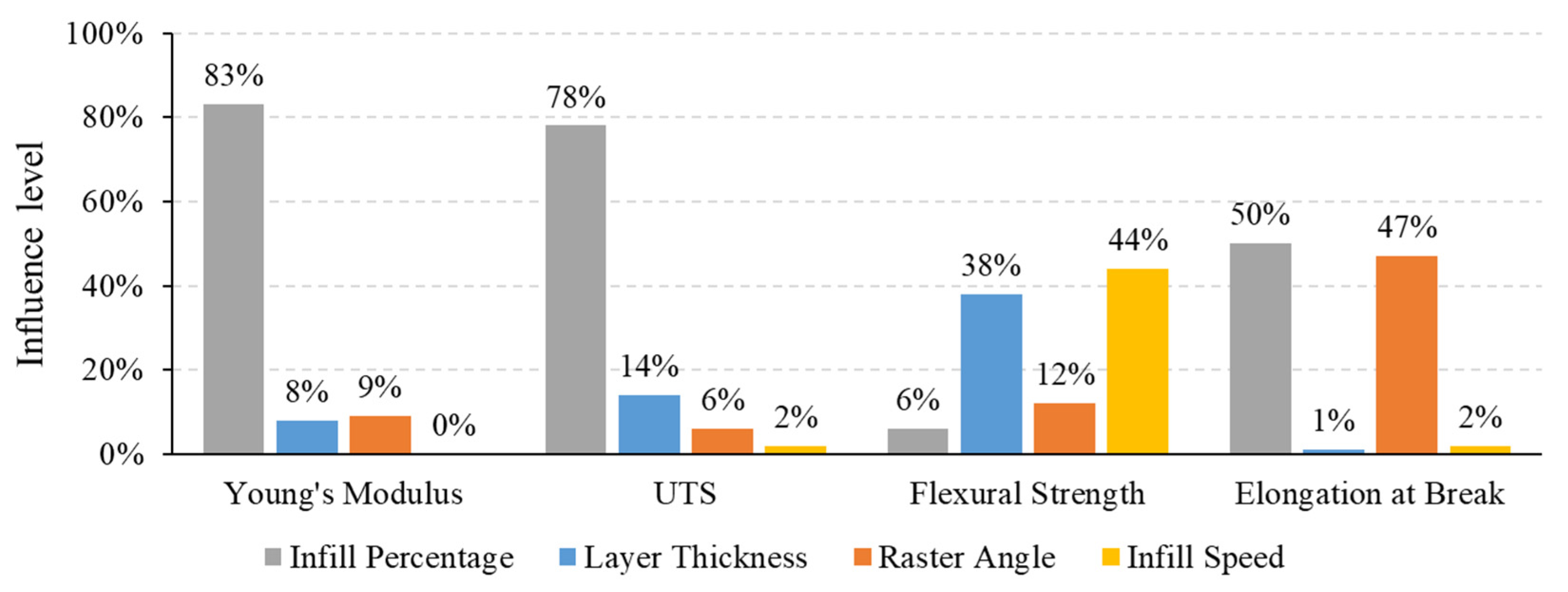
6.5. PETG Mechanical Properties Sensitivity Study Using ANOVA
7. Conclusions
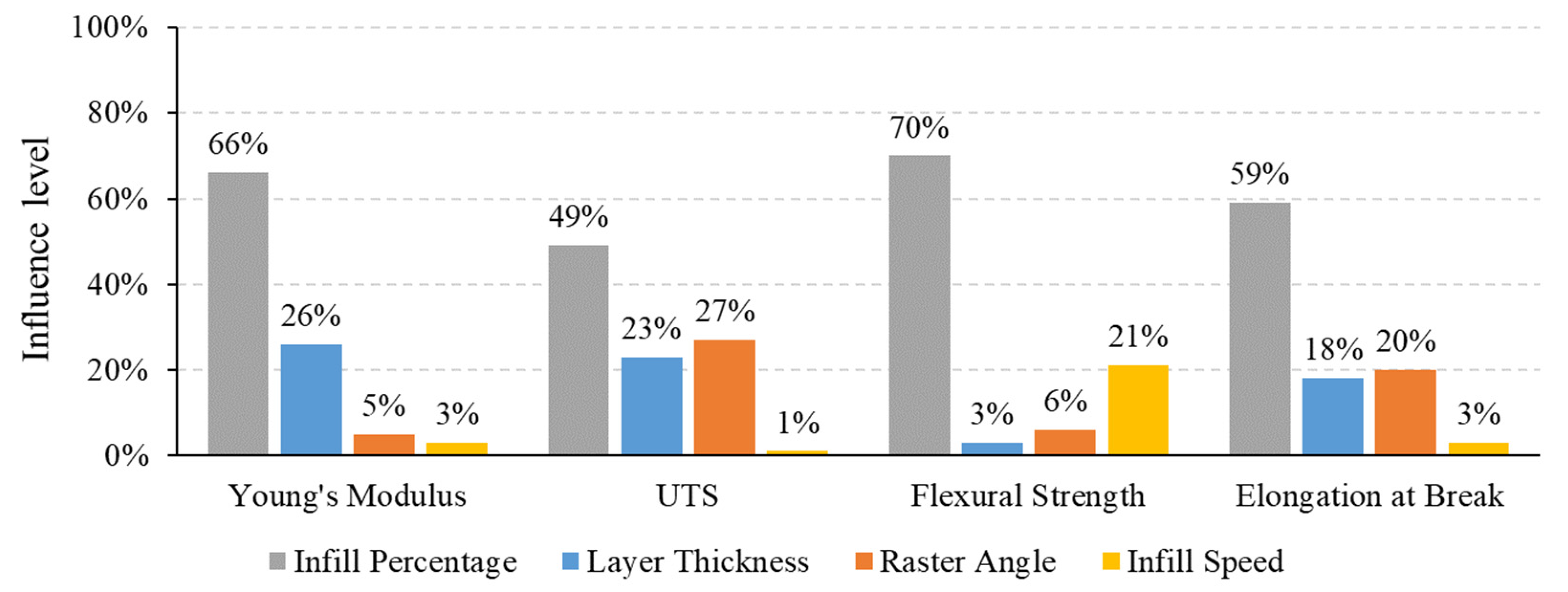
- Infill percentage is the most influential process parameter on all the material’s mechanical properties.
- Infill percentage had the most significant influence on PLA and ABS mechanical behaviors.
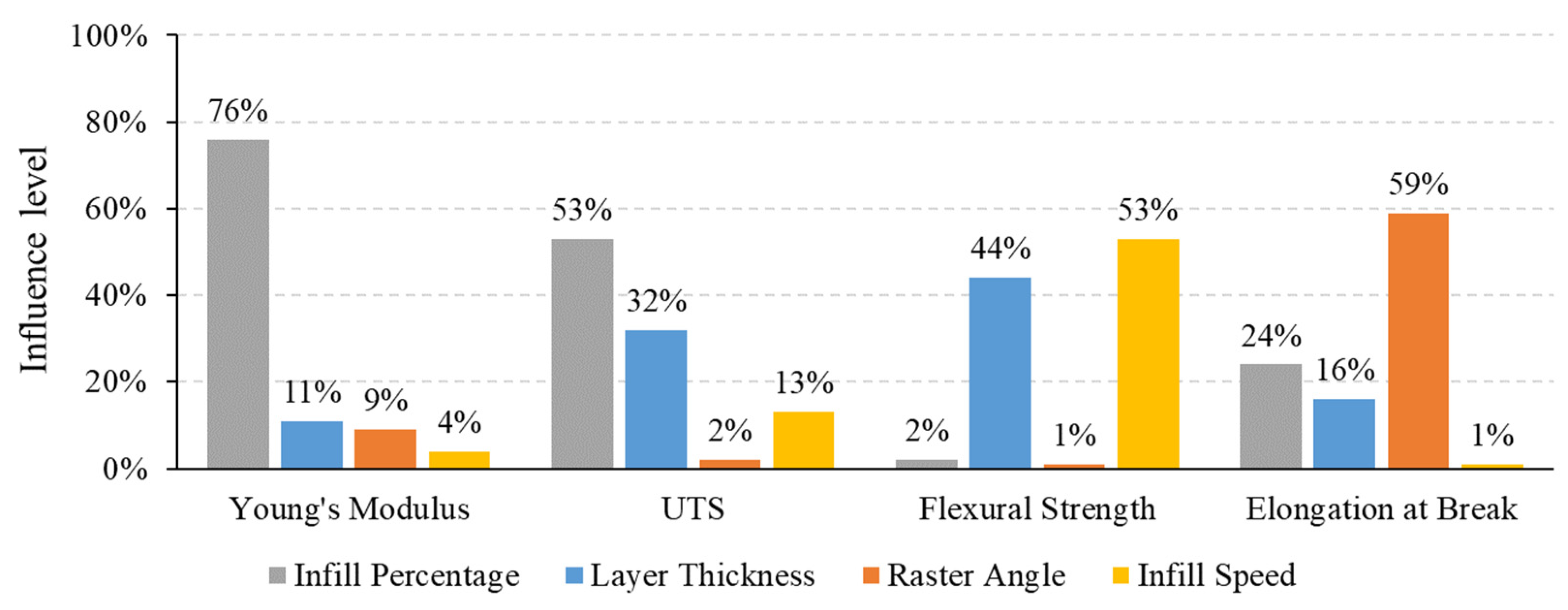
- The Young’s modulus and UTS of PEEK were found to be affected mainly by infill percentage. Flexural strength and fractural strain were significantly affected by printing speed and infill percentage, respectively.
- The Young’s modulus and UTS of PETG were affected mainly by infill percentage. Additionally, printing speed mainly affected flexural strength, and raster angle greatly influenced elongation at break.
- The outcomes of this study demonstrate that the material’s mechanical properties depend greatly on the process parameters selected. It was difficult to conduct a study with fixed process ranges, as other FDM parameters (such as raster width, shell thickness, infill pattern, and nozzle temperature) were not constant yet in similar ranges, due to the lack of data in the literature. This study was based on data available in the literature, and different studies used different process ranges for each material. Therefore, it is recommended that a similar study be conducted with a fixed set of process parameter ranges for all materials (PLA, ABS, PEEK, and PETG) to further investigate the influence of process parameters on mechanical properties.
Author Contributions
Funding
Data Availability Statement
Acknowledgments
Conflicts of Interest
References
- Ngo, T.D.; Kashani, A.; Imbalzano, G.; Nguyen, K.T.; Hui, D. Additive manufacturing (3D printing): A review of materials, methods, applications and challenges. Compos. Part B Eng. 2018, 143, 172–196. [Google Scholar] [CrossRef]
- Korpela, J.; Kokkari, A.; Korhonen, H.; Malin, M.; Närhi, T.; Seppälä, J. Biodegradable and bioactive porous scaffold structures prepared using fused deposition modeling. J. Biomed. Mater. Res. Part B Appl. Biomater. 2013, 101, 610–619. [Google Scholar] [CrossRef]
- Duda, T.; Raghavan, L.V. 3D metal printing technology: The need to re-invent design practice. AI Soc. 2018, 33, 241–252. [Google Scholar] [CrossRef]
- Popescu, D.; Zapciu, A.; Amza, C.; Baciu, F.; Marinescu, R. FDM process parameters influence over the mechanical properties of polymer specimens: A review. Polym. Test. 2018, 69, 157–166. [Google Scholar] [CrossRef]
- Garcia, E.A.; Ayranci, C.; Qureshi, A.J. Material property-manufacturing process optimization for form 2 vat-photo polymerization 3D Printers. J. Manuf. Mater. Process. 2020, 4, 12. [Google Scholar] [CrossRef] [Green Version]
- Raney, K.; Lani, E.; Kalla, D.K. Experimental characterization of the tensile strength of ABS parts manufactured by fused deposition modeling process. Mater. Today Proc. 2017, 4, 7956–7961. [Google Scholar] [CrossRef]
- Nancharaiah, T.; Raju, D.R.; Raju, V.R. An experimental investigation on surface quality and dimensional accuracy of FDM components. Int. J. Emerg. Technol. 2010, 1, 106–111. [Google Scholar]
- Nidagundi, V.B.; Keshavamurthy, R.; Prakash, C. Studies on Parametric Optimization for Fused Deposition Modelling Process. Mater. Today Proc. 2015, 2, 1691–1699. [Google Scholar] [CrossRef]
- Durgun, I.; Ertan, R. Experimental investigation of FDM process for improvement of mechanical properties and production cost. Rapid Prototyp. J. 2014, 20, 228–235. [Google Scholar] [CrossRef]
- Letcher, T.; Rankouhi, B.; Javadpour, S. Experimental Study of Mechanical Properties of Additively Manufactured ABS Plastic as a Function of Layer Parameters. In Proceedings of the ASME 2015 International Mechanical Engineering Congress and Exposition (IMECE), Houston, TX, USA, 13–19 November 2015; American Society of Mechanical Engineers Digital Collection: Houston, TX, USA, 2015. [Google Scholar]
- Krajangsawasdi, N.; Blok, L.G.; Hamerton, I.; Longana, M.L.; Woods, B.K.S.; Ivanov, D.S. Fused deposition modelling of fibre reinforced polymer composites: A parametric review. J. Compos. Sci. 2021, 5, 29. [Google Scholar] [CrossRef]
- Nancharaiah, T. Optimization of process parameters in FDM process using design of experiments. Int. J. Emerg. Technol. 2011, 2, 100–102. [Google Scholar]
- Sood, A.K.; Ohdar, R.K.; Mahapatra, S.S. Experimental investigation and empirical modelling of FDM process for compressive strength improvement. Int. J. Adv. Res. 2012, 3, 81–90. [Google Scholar] [CrossRef] [Green Version]
- Sood, A.K.; Ohdar, R.; Mahapatra, S.S. Parametric appraisal of mechanical property of fused deposition modelling processed parts. Mater. Des. 2010, 31, 287–295. [Google Scholar] [CrossRef]
- Wu, W.; Geng, P.; Li, G.; Zhao, D.; Zhang, H.; Zhao, J. Influence of Layer Thickness and Raster Angle on the Mechanical Properties of 3D-Printed PEEK and a Comparative Mechanical Study between PEEK and ABS. Materials 2015, 8, 5834–5846. [Google Scholar] [CrossRef]
- Lee, B.H.; Abdullah, J.; Khan, Z.A. Optimization of rapid prototyping parameters for production of flexible ABS object. J. Mater. Process. Technol. 2005, 169, 54–61. [Google Scholar] [CrossRef]
- Sun, Q.; Rizvi, G.; Bellehumeur, C.; Gu, P. Effect of processing conditions on the bonding quality of FDM polymer filaments. Rapid Prototyp. J. 2008, 14, 72–80. [Google Scholar] [CrossRef]
- Ahn, S.H.; Montero, M.; Odell, D.; Roundy, S.; Wright, P.K. Anisotropic material properties of fused deposition modeling ABS. Rapid Prototyp. J. 2002, 8, 248–257. [Google Scholar] [CrossRef] [Green Version]
- Bakar, N.S.A.; Alkahari, M.R.; Boejang, H. Analysis on fused deposition modelling performance. J. Zhejiang Univ. Sci. A 2010, 11, 972–977. [Google Scholar] [CrossRef]
- Rajpurohit, S.; Dave, H.K. Analysis of tensile strength of a fused filament fabricated PLA part using an open-source 3D printer. Int. J. Adv. Manuf. Technol. 2019, 101, 1525–1536. [Google Scholar] [CrossRef]
- Srinivasan, R.; Pridhar, T.; Ramprasath, L.; Charan, N.S.; Ruban, W. Prediction of tensile strength in FDM printed ABS parts using response surface methodology (RSM). Mater. Today Proc. 2020, 27, 1827–1832. [Google Scholar] [CrossRef]
- Bellini, A.; Güçeri, S. Mechanical characterization of parts fabricated using fused deposition modeling. Rapid Prototyp. J. 2003, 9, 252–264. [Google Scholar] [CrossRef]
- Ang, K.C.; Leong, K.F.; Chua, C.K.; Chandrasekaran, M. Investigation of the mechanical properties and porosity relationships in fused deposition modelling-fabricated porous structures. Rapid Prototyp. J. 2006, 12, 100–105. [Google Scholar] [CrossRef]
- Chang, D.-Y.; Huang, B.-H. Studies on profile error and extruding aperture for the RP parts using the fused deposition modeling process. Int. J. Adv. Manuf. Technol. 2011, 53, 1027–1037. [Google Scholar] [CrossRef]
- Croccolo, D.; De Agostinis, M.; Olmi, G. Experimental characterization and analytical modelling of the mechanical behaviour of fused deposition processed parts made of ABS-M30. Comput. Mater. Sci. 2013, 79, 506–518. [Google Scholar] [CrossRef]
- Magalhães, L.; Volpato, N.; Luersen, M. Evaluation of stiffness and strength in fused deposition sandwich specimens. J. Braz. Soc. Mech. Sci. Eng. 2014, 36, 449–459. [Google Scholar] [CrossRef]
- Carneiro, O.S.; Silva, A.; Gomes, R. Fused deposition modeling with polypropylene. Mater. Des. 2015, 83, 768–776. [Google Scholar] [CrossRef]
- Cantrell, J.T.; Rohde, S.; Damiani, D.; Gurnani, R.; DiSandro, L.; Anton, J.; Young, A.; Jerez, A.; Steinbach, D.; Kroese, C.; et al. Experimental characterization of the mechanical properties of 3D-printed ABS and polycarbonate parts. Rapid Prototyp. J. 2017, 23, 811–824. [Google Scholar] [CrossRef]
- Arif, M.; Kumar, S.; Varadarajan, K.; Cantwell, W. Performance of biocompatible PEEK processed by fused deposition additive manufacturing. Mater. Des. 2018, 146, 249–259. [Google Scholar] [CrossRef]
- Gebisa, A.W.; Lemu, H.G. Investigating effects of Fused-Deposition Modeling (FDM) processing parameters on flexural properties of ULTEM 9085 using designed experiment. Materials 2018, 11, 500. [Google Scholar] [CrossRef] [Green Version]
- Rayegani, F.; Onwubolu, G.C. Fused deposition modelling (FDM) process parameter prediction and optimization using group method for data handling (GMDH) and differential evolution (DE). Int. J. Adv. Manuf. Technol. 2014, 73, 509–519. [Google Scholar] [CrossRef]
- Qattawi, A.; Alrawi, B.; Guzman, A. Experimental optimization of fused deposition modelling processing parameters: A design-for-manufacturing approach. Procedia Manuf. 2017, 10, 791–803. [Google Scholar] [CrossRef]
- Panda, S.K.; Padhee, S.; Sood, A.K.; Mahapatra, S.S. Optimization of Fused Deposition Modelling (FDM) Process Parameters Using Bacterial Foraging Technique. Intell. Inf. Manag. 2009, 1, 89–97. [Google Scholar] [CrossRef] [Green Version]
- Akande, S.O. Dimensional Accuracy and Surface Finish Optimization of Fused Deposition Modelling Parts using Desirability Function Analysis. Int. J. Eng. Res. Technol. 2015, 4, 196–202. [Google Scholar] [CrossRef]
- Gurrala, P.K.; Regalla, S.P. Multi-objective optimisation of strength and volumetric shrinkage of FDM parts: A multi-objective optimization scheme is used to optimize the strength and volumetric shrinkage of FDM parts considering different process parameters. Virtual Phys. Prototyp. 2014, 9, 127–138. [Google Scholar] [CrossRef]
- Rao, R.V.; Rai, D.P. Optimization of fused deposition modeling process using teaching-learning-based optimization algorithm. Eng. Sci. Technol. Int. J. 2016, 19, 587–603. [Google Scholar] [CrossRef] [Green Version]
- Algarni, M. The Influence of Raster Angle and Moisture Content on the Mechanical Properties of PLA Parts Produced by Fused Deposition Modeling. Polymers 2021, 13, 237. [Google Scholar] [CrossRef] [PubMed]
- Kiendl, J.; Gao, C. Controlling toughness and strength of FDM 3D-printed PLA components through the raster layup. Compos. Part B Eng. 2020, 180, 107562. [Google Scholar] [CrossRef]
- Rajpurohit, S.R.; Dave, H.K. Impact strength of 3D printed PLA using open source FFF-based 3D printer. Prog. Addit. Manuf. 2021, 6, 119–131. [Google Scholar] [CrossRef]
- Sukanto, H.; Smaradhana, D.F.; Triyono, J.; Wicaksono, P. Investigating the Effect of Layer Thickness on the Product Quality of PLA Manufactured by 3D Printing Technique. In Proceedings of the 6th International Conference and Exhibition on Sustainable Energy and Advanced Materials, Surakarta, Indonesia, 16–17 October 2019; Springer: Singapore, 2020; pp. 811–818. [Google Scholar]
- Tymrak, B.; Kreiger, M.; Pearce, J. Mechanical properties of components fabricated with open-source 3-D printers under realistic environmental conditions. Mater. Des. 2014, 58, 242–246. [Google Scholar] [CrossRef] [Green Version]
- Lanzotti, A.; Grasso, M.; Staiano, G.; Martorelli, M. The impact of process parameters on mechanical properties of parts fabricated in PLA with an open-source 3-D printer. Rapid Prototyp. J. 2015, 21, 604–617. [Google Scholar] [CrossRef] [Green Version]
- Torres, J.; Cotelo, J.; Karl, J.; Gordon, A.P. Mechanical property optimization of FDM PLA in shear with multiple objectives. Jom 2015, 67, 1183–1193. [Google Scholar] [CrossRef]
- Li, H.; Wang, T.; Sun, J.; Yu, Z. The effect of process parameters in fused deposition modelling on bonding degree and mechanical properties. Rapid Prototyp. J. 2018, 24, 80–92. [Google Scholar] [CrossRef]
- Torres, J.; Cole, M.; Owji, A.; DeMastry, Z.; Gordon, A.P. An approach for mechanical property optimization of fused deposition modeling with polylactic acid via design of experiments. Rapid Prototyp. J. 2016, 22, 387–404. [Google Scholar] [CrossRef]
- Liu, X.; Zhang, M.; Li, S.; Si, L.; Peng, J.; Hu, Y. Mechanical property parametric appraisal of fused deposition modeling parts based on the gray Taguchi method. Int. J. Adv. Manuf. Technol. 2017, 89, 2387–2397. [Google Scholar] [CrossRef]
- Abbas, T.; Othman, F.M.; Ali, H.B. Effect of infill Parameter on compression property in FDM Process. Int. J. Eng. Res. Appl. 2017, 7, 16–19. [Google Scholar]
- Abeykoon, C.; Sri-Amphorn, P.; Fernando, A. Optimization of fused deposition modeling parameters for improved PLA and ABS 3D printed structures. Int. J. Light. Mater. Manuf. 2020, 3, 284–297. [Google Scholar] [CrossRef]
- Galeja, M.; Hejna, A.; Kosmela, P.; Kulawik, A. Static and Dynamic Mechanical Properties of 3D Printed ABS as a Function of Raster Angle. Materials 2020, 13, 297. [Google Scholar] [CrossRef] [Green Version]
- Guimarães, A.L.A.; Neto, V.G.; Foschini, C.R.; Azambuja, M.D.A.; Hellmeister, L.A.V. Influence of ABS print parameters on a 3D open-source, self-replicable printer. Rapid Prototyp. J. 2020, 26, 1733–1738. [Google Scholar] [CrossRef]
- Dwiyati, S.T.; Kholil, A.; Riyadi, R.; Putra, S.E. Influence of layer thickness and 3D printing direction on tensile properties of ABS material. J. Phys. Conf. Ser. 2019, 1402, 066014. [Google Scholar] [CrossRef]
- Isaac, J.P.; Dondeti, S.; Tippur, H.V. Fracture behavior of additively printed ABS: Effects of print architecture and loading rate. Int. J. Solids Struct. 2021, 212, 80–95. [Google Scholar] [CrossRef]
- Fernandez-Vicente, M.; Calle, W.; Ferrandiz, S.; Conejero, A. Effect of infill parameters on tensile mechanical behavior in desktop 3D printing. 3D Print. Addit. Manuf. 2016, 3, 183–192. [Google Scholar] [CrossRef]
- Alvarez, K.L.C.; Lagos, R.F.C.; Aizpun, M. Investigating the influence of infill percentage on the mechanical properties of fused deposition modelled ABS parts. Ing. E Investig. 2016, 36, 110–116. [Google Scholar] [CrossRef] [Green Version]
- Wang, P.; Zou, B.; Xiao, H.; Ding, S.; Huang, C. Effects of printing parameters of fused deposition modeling on mechanical properties, surface quality, and microstructure of PEEK. J. Mater. Process. Technol. 2019, 271, 62–74. [Google Scholar] [CrossRef]
- Deng, X.; Zeng, Z.; Peng, B.; Yan, S.; Ke, W. Mechanical properties optimization of poly-ether-ether-ketone via fused deposition modeling. Materials 2018, 11, 216. [Google Scholar] [CrossRef] [PubMed] [Green Version]
- Motaparti, K.P. Effect of Build Parameters on Mechanical Properties of Ultem 9085 Parts by Fused Deposition Modeling. Master’s Thesis, Missouri University of Science and Technology, Rolla, MO, USA, 2016. Available online: https://scholarsmine.mst.edu/masters_theses/7513 (accessed on 1 May 2021).
- Liaw, C.-Y.; Tolbert, J.W.; Chow, L.W.; Guvendiren, M. Interlayer bonding strength of 3D printed PEEK specimens. Soft Matter 2021, 17, 4775–4789. [Google Scholar] [CrossRef] [PubMed]
- Dev, S.; Srivastava, R. Effect of infill parameters on material sustainability and mechanical properties in fused deposition modelling process: A case study. Prog. Addit. Manuf. 2021, 1–12. [Google Scholar] [CrossRef]
- Srinivasan, R.; Ruban, W.; Deepanraj, A.; Bhuvanesh, R. Effect on infill density on mechanical properties of PETG part fabricated by fused deposition modelling. Mater. Today Proc. 2020, 27, 1838–1842. [Google Scholar] [CrossRef]
- Srinivasan, R.; Kumar, K.N.; Ibrahim, A.J.; Anandu, K.; Gurudhevan, R. Impact of fused deposition process parameter (infill pattern) on the strength of PETG part. Mater. Today Proc. 2020, 27, 1801–1805. [Google Scholar] [CrossRef]
- Teraiya, S.; Vyavahare, S.; Kumar, S. Experimental Investigation on Influence of Process Parameters on Mechanical Properties of PETG Parts Made by Fused Deposition Modelling. In Advances in Manufacturing Processes; Springer: Singapore, 2021; pp. 283–293. [Google Scholar]
- Hsueh, M.-H.; Lai, C.-J.; Wang, S.-H.; Zeng, Y.-S.; Hsieh, C.-H.; Pan, C.-Y.; Huang, W.-C. Effect of Printing Parameters on the Thermal and Mechanical Properties of 3D-Printed PLA and PETG, Using Fused Deposition Modeling. Polymers 2021, 13, 1758. [Google Scholar] [CrossRef]
- A Standard: “ISO/ASTM 52900: 2015 Additive Manufacturing-General Principles-Terminology”; ASTM F2792-10e1; ASTM International: West Conshohocken, PA, USA, 2015.
- ASTM-D638: “Standard Test Method for Tensile Properties of Plastics”; ASTM International: West Conshohocken, PA, USA, 2010.
- ISO/ASTM:“Standard Terminology for Additive Manufacturing-Coordinate Systems and Test Methodologies”; ASTM International: West Conshohocken, PA, USA, 2013.
- Dey, A.; Yodo, N. A Systematic Survey of FDM Process Parameter Optimization and Their Influence on Part Characteristics. J. Manuf. Mater. Process. 2019, 3, 64. [Google Scholar] [CrossRef] [Green Version]
- Lee, C.; Kim, S.; Kim, H.; Ahn, S. Measurement of anisotropic compressive strength of rapid prototyping parts. J. Mater. Process. Technol. 2007, 187, 627–630. [Google Scholar] [CrossRef]
- Vyavahare, S.; Teraiya, S.; Panghal, D.; Kumar, S. Fused deposition modelling: A review. Rapid Prototyp. J. 2019, 26, 176–201. [Google Scholar] [CrossRef]
- Tsiolikas, A.; Mikrou, T.; Vakouftsi, F.; Aslani, K.-E.; Kechagias, J. (Ioannis) Robust design application for optimizing ABS fused filament fabrication process: A case study. IOP Conf. Ser. Mater. Sci. Eng. 2019, 564, 012021. [Google Scholar] [CrossRef]
- Li, H.; Wang, T.; Yu, Z. The Quantitative Research of Interaction between Key Parameters and the Effects on Mechanical Property in FDM. Adv. Mater. Sci. Eng. 2017, 2017, 1–15. [Google Scholar] [CrossRef] [Green Version]
- Pagano, C.; Basile, V.; Modica, F.; Fassi, I. Micro-FDM process capability and post-processing effects on mechanical properties. In AIP Conference Proceedings; AIP Publishing LLC: Melville, NY, USA, 2019; Volume 2139, p. 190002. [Google Scholar]
- Montero, M.; Roundy, S.; Odell, D.; Ahn, S.-H.; Wright, P.K. Material characterization of fused deposition modeling (FDM) ABS by designed experiments. Soc. Manuf. Eng. 2001, 10, 1–21. [Google Scholar]
- Basile, V.; Modica, F.; Fontana, G.; Ruggeri, S.; Fassi, I. Improvements in accuracy of fused deposition modeling via integration of low-cost on-board vision systems. J. Micro Nano-Manuf. 2020, 8. [Google Scholar] [CrossRef] [Green Version]
- Chacón, J.; Caminero, M.A.; García-Plaza, E.; Núnez, P.J. Additive manufacturing of PLA structures using fused deposition modelling: Effect of process parameters on mechanical properties and their optimal selection. Mater. Des. 2017, 124, 143–157. [Google Scholar] [CrossRef]
- Ahmed, A.; Susmel, L. A material length scale-based methodology to assess static strength of notched additively manufactured polylactide (PLA). Fatigue Fract. Eng. Mater. Struct. 2018, 41, 2071–2098. [Google Scholar] [CrossRef]
- Zhang, X.; Chen, L.; Mulholland, T.; Osswald, T.A. Effects of raster angle on the mechanical properties of PLA and Al/PLA composite part produced by fused deposition modeling. Polym. Adv. Technol. 2019, 30, 2122–2135. [Google Scholar] [CrossRef]
- Cho, E.E.; Hein, H.H.; Lynn, Z.; Hla, S.J.; Tran, T. Investigation on influence of infill pattern and layer thickness on mechanical strength of PLA material in 3D printing technology. J. Eng. Sci. Res. 2019, 3, 27–37. [Google Scholar]
- Luzanin, O.; Movrin, D.; Stathopoulos, V.; Pandis, P.; Radusin, T.; Guduric, V. Impact of processing parameters on tensile strength, in-process crystallinity and mesostructure in FDM-fabricated PLA specimens. Rapid Prototyp. J. 2019, 25, 1398–1410. [Google Scholar] [CrossRef]
- Zhao, Y.; Chen, Y.; Zhou, Y. Novel mechanical models of tensile strength and elastic property of FDM AM PLA materials: Experimental and theoretical analyses. Mater. Des. 2019, 181, 108089. [Google Scholar] [CrossRef]
- Rodríguez-Panes, A.; Claver, J.; Camacho, A.M. The Influence of Manufacturing Parameters on the Mechanical Behaviour of PLA and ABS Pieces Manufactured by FDM: A Comparative Analysis. Materials 2018, 11, 1333. [Google Scholar] [CrossRef] [PubMed] [Green Version]
- Rismalia, M.; Hidajat, S.C.; Permana, I.G.R.; Hadisujoto, B.; Muslimin, M.; Triawan, F. Infill pattern and density effects on the tensile properties of 3D printed PLA material. J. Phys. Conf. Ser. 2019, 1402, 044041. [Google Scholar] [CrossRef] [Green Version]
- Mazurchevici, A.-D.; Popa, R.-I.; Carausu, C.; Mazurchevici, S.-N.; Nedelcu, D. Influence of Layer Thickness, Infill Rate and Orientation on Thermal and Structural Loading of FDM Parts. In Advances in Manufacturing Processes; Springer: Berlin/Heidelberg, Germany, 2021; pp. 263–282. [Google Scholar]
- Chandravadia, M.R.; Chudasama, M.K. Experimental Investigation on Tensile Properties of Nylon Glass Fibre Material Made Using Fused Deposition Modelling Process. In Advances in Manufacturing Processes; Springer: Berlin/Heidelberg, Germany, 2021; pp. 329–342. [Google Scholar]
- Murugan, R.; Mitilesh, R.N.; Singamneni, S. Influence of process parameters on the mechanical behaviour and processing time of 3D printing. Int. J. Mod. Manuf. Technol. 2019, 1, 21–27. [Google Scholar]
- Dave, H.K.; Rajpurohit, S.R.; Patadiya, N.H.; Dave, S.J.; Kumar, S.; Sharma; Thambad, S.S.; Srinivasn, V.P.; Sheth, K. Compressive strength of PLA based scaffolds: Effect of layer height, infill density and print speed. Int. J. Mod. Manuf. Technol. 2019, 11, 21–27. [Google Scholar]
- Fatimatuzahraa, A.; Farahaina, B.; Yusoff, W. The Effect of Employing Different Raster Orientations on the Mechanical Properties and Microstructure of Fused Deposition Modeling Parts. In Proceedings of the 2011 IEEE Symposium on Business, Engineering and Industrial Applications (ISBEIA), Langkawi, Malaysia, 25–28 September 2011; pp. 22–27. [Google Scholar]
- Sharma, M.; Ziemian, C. Anisotropic mechanical properties of ABS parts fabricated by fused deposition modelling. Mech. Eng. 2012, 23, 2397. [Google Scholar] [CrossRef] [Green Version]
- Ziemian, S.; Okwara, M.; Ziemian, C.W. Tensile and fatigue behavior of layered acrylonitrile butadiene styrene. Rapid Prototyp. J. 2015, 21, 270–278. [Google Scholar] [CrossRef]
- Rankouhi, B.; Javadpour, S.; Delfanian, F.; Letcher, T. Failure Analysis and Mechanical Characterization of 3D Printed ABS With Respect to Layer Thickness and Orientation. J. Fail. Anal. Prev. 2016, 16, 467–481. [Google Scholar] [CrossRef]
- Nomani, J.; Wilson, D.; Paulino, M.; Mohammed, M.I. Effect of layer thickness and cross-section geometry on the tensile and compression properties of 3D printed ABS. Mater. Today Commun. 2020, 22, 100626. [Google Scholar] [CrossRef]
- Suaidi, S.N.S.W.; Azizul, M.A.; Sulaiman, S.; Hao, T.Y. Effect of fused deposition modelling process parameters on the quality of ABS product. J. Ind. Eng. Innov. 2020, 2, 9. [Google Scholar]
- Baich, L.; Manogharan, G.; Marie, H. Study of infill print design on production cost-time of 3D printed ABS parts. Int. J. Rapid Manuf. 2015, 5, 308. [Google Scholar] [CrossRef]
- Yadav, D.; Chhabra, D.; Garg, R.K.; Ahlawat, A.; Phogat, A. Optimization of FDM 3D printing process parameters for multi-material using artificial neural network. Mater. Today Proc. 2020, 21, 1583–1591. [Google Scholar] [CrossRef]
- Samykano, M.; Selvamani, S.K.; Kadirgama, K.; Ngui, W.K.; Kanagaraj, G.; Sudhakar, K. Mechanical property of FDM printed ABS: Influence of printing parameters. Int. J. Adv. Manuf. Technol. 2019, 102, 2779–2796. [Google Scholar] [CrossRef]
- Abbott, A.; Tandon, G.; Bradford, R.; Koerner, H.; Baur, J. Process-structure-property effects on ABS bond strength in fused filament fabrication. Addit. Manuf. 2018, 19, 29–38. [Google Scholar] [CrossRef]
- Domingo-Espin, M.; Travieso-Rodriguez, J.A.; Jerez-Mesa, R.; Lluma-Fuentes, J. Fatigue Performance of ABS Specimens Obtained by Fused Filament Fabrication. Materials 2018, 11, 2521. [Google Scholar] [CrossRef] [PubMed] [Green Version]
- Rinaldi, M.; Cecchini, F.; Pigliaru, L.; Ghidini, T.; Lumaca, F.; Nanni, F. Additive Manufacturing of Polyether Ether Ketone (PEEK) for Space Applications: A Nanosat Polymeric Structure. Polymers 2020, 13, 11. [Google Scholar] [CrossRef]
- Li, Y.; Lou, Y. Tensile and Bending Strength Improvements in PEEK Parts Using Fused Deposition Modelling 3D Printing Considering Multi-Factor Coupling. Polymers 2020, 12, 2497. [Google Scholar] [CrossRef]
- Rinaldi, M.; Ghidini, T.; Cecchini, F.; Brandao, A.; Nanni, F. Additive layer manufacturing of poly (ether ether ketone) via FDM. Compos. Part B Eng. 2018, 145, 162–172. [Google Scholar] [CrossRef]
- Wang, Y.; Müller, W.-D.; Rumjahn, A.; Schmidt, F.; Schwitalla, A.D. Mechanical properties of fused filament fabricated PEEK for biomedical applications depending on additive manufacturing parameters. J. Mech. Behav. Biomed. Mater. 2021, 115, 104250. [Google Scholar] [CrossRef]
- Basgul, C.; Yu, T.; MacDonald, D.W.; Siskey, R.; Marcolongo, M.; Kurtz, S.M. Does annealing improve the interlayer adhesion and structural integrity of FFF 3D printed PEEK lumbar spinal cages? J. Mech. Behav. Biomed. Mater. 2020, 102, 103455. [Google Scholar] [CrossRef]
- Mercado-Colmenero, J.M.; La Rubia, M.D.; Mata-Garcia, E.; Rodriguez-Santiago, M.; Martin-Doñate, C. Experimental and Numerical Analysis for the Mechanical Characterization of PETG Polymers Manufactured with FDM Technology under Pure Uniaxial Compression Stress States for Architectural Applications. Polymers 2020, 12, 2202. [Google Scholar] [CrossRef]
- Messimer, S.L.; Pereira, T.R.; Patterson, A.E.; Lubna, M.; Drozda, F.O. Full-Density Fused Deposition Modeling Dimensional Error as a Function of Raster Angle and Build Orientation: Large Dataset for Eleven Materials. J. Manuf. Mater. Process. 2019, 3, 6. [Google Scholar] [CrossRef] [Green Version]
- Dolzyk, G.; Jung, S. Tensile and Fatigue Analysis of 3D-Printed Polyethylene Terephthalate Glycol. J. Fail. Anal. Prev. 2019, 19, 511–518. [Google Scholar] [CrossRef]
- Durgashyam, K.; Reddy, M.I.; Balakrishna, A.; Satyanarayana, K. Experimental investigation on mechanical properties of PETG material processed by fused deposition modeling method. Mater. Today Proc. 2019, 18, 2052–2059. [Google Scholar] [CrossRef]
- Srinivasan, R.; Prathap, P.; Raj, A.; Kannan, S.A.; Deepak, V. Influence of fused deposition modeling process parameters on the mechanical properties of PETG parts. Mater. Today Proc. 2020, 27, 1877–1883. [Google Scholar] [CrossRef]
- Kumar, M.A.; Khan, M.; Mishra, S. Effect of machine parameters on strength and hardness of FDM printed carbon fiber reinforced PETG thermoplastics. Mater. Today Proc. 2020, 27, 975–983. [Google Scholar] [CrossRef]


| Properties | PLA | ABS | PEEK | PETG |
|---|---|---|---|---|
| Extrusion temperature (°C) | 190–210 | 220–260 | 380–410 | 230–250 |
| Bed platform Temp (°C) | 25–80 | 90–110 | 90–150 | 60–80 |
| Density (g/cm3) | 1.25 | 1.04 | 1.30 | 1.23 |
| Tensile strength (MPa) | 65 | 43 | 100 | 49 |
| Flexural strength (MPa) | 97 | 66 | 170 | 70 |
| Izod impact strength (kJ/m2) | 4 | 19 | 7 | 7.6 |
| Recyclability | Yes | Yes | Yes | Yes |
| Biodegradability | Yes | No | No | No |
| Fume toxicity | Very low | Medium | Low | Very low |
| Process Parameter | Range Selected | Low | Middle | High |
|---|---|---|---|---|
| Raster angle | 0°–90° | 0° | 45° | 90° |
| Layer thickness | 0.1–0.3 mm | 0.1 mm | 0.2 mm | 0.3 mm |
| Infill percentage | 20–100% | 20% | 50% | 100% |
| Printing speed | 35–65 mm/s | 35 mm/s | 50 mm/s | 65 mm/s |
| Material Property | First | Second | Third | Fourth |
|---|---|---|---|---|
| Young’s Modulus | Infill Percentage | Layer Thickness | Raster Angle | Printing speed |
| UTS | Infill Percentage | Raster Angle | Printing speed | Layer Thickness |
| Flexural Strength | Infill Percentage | Printing speed | Raster Angle | Printing speed |
| Elongation at break | Infill Percentage | Raster Angle | Layer Thickness | Printing speed |
| Process Parameter | Range Selected | Low | Middle | High |
|---|---|---|---|---|
| Raster angle | 0°–90° | 0° | 45° | 90° |
| Layer thickness | 0.1–0.3 mm | 0.1 mm | 0.2 mm | 0.3 mm |
| Infill percentage | 60–100% | 60% | 80% | 100% |
| Printing speed | 20–40 mm/s | 20 mm/s | 30 mm/s | 40 mm/s |
| Material Property | First | Second | Third | Fourth |
|---|---|---|---|---|
| Young’s Modulus | Infill Percentage | Layer Thickness | Raster Angle | Printing speed |
| UTS | Infill Percentage | Layer Thickness | Raster Angle | Printing speed |
| Flexural Strength | Infill Percentage | Printing speed | Raster Angle | Layer Thickness |
| Elongation at break | Infill Percentage | Raster Angle | Layer Thickness | Printing speed |
| Process Parameter | Range Selected | Low | Middle | High |
|---|---|---|---|---|
| Raster angle | 0°–90° | 0° | 45° | 90° |
| Layer thickness | 0.07–0.21 mm | 0.07 mm | 0.14 mm | 0.21 mm |
| Infill percentage | 20–100% | 20% | 50% | 100% |
| Printing speed | 10–30 mm/s | 10 mm/s | 20 mm/s | 30 mm/s |
| Material Property | First | Second | Third | Fourth |
|---|---|---|---|---|
| Young’s Modulus | Infill Percentage | Raster Angle | Layer Thickness | Printing speed |
| UTS | Infill Percentage | Layer Thickness | Raster Angle | Printing speed |
| Flexural Strength | Printing speed | Layer Thickness | Raster Angle | Infill Percentage |
| Elongation at break | Infill Percentage | Raster Angle | Printing speed | Layer Thickness |
| Process Parameter | Range Selected | Low | Middle | High |
|---|---|---|---|---|
| Raster angle | 0°–90° | 0° | 45° | 90° |
| Layer thickness | 0.2–0.4 mm | 0.2 mm | 0.3 mm | 0.4 mm |
| Infill percentage | 50–100% | 50% | 75% | 100% |
| Printing speed | 15–35 mm/s | 15 mm/s | 25 mm/s | 35 mm/s |
| Material Property | First | Second | Third | Fourth |
|---|---|---|---|---|
| Young’s Modulus | Infill percentage | Layer thickness | Raster angle | Printing speed |
| UTS | Infill percentage | Layer thickness | Printing speed | Raster angle |
| Flexural Strength | Printing speed | Layer thickness | Infill percentage | Raster angle |
| Elongation at break | Raster angle | Infill percentage | Layer thickness | Printing speed |
Publisher’s Note: MDPI stays neutral with regard to jurisdictional claims in published maps and institutional affiliations. |
© 2021 by the authors. Licensee MDPI, Basel, Switzerland. This article is an open access article distributed under the terms and conditions of the Creative Commons Attribution (CC BY) license (https://creativecommons.org/licenses/by/4.0/).
Share and Cite
Algarni, M.; Ghazali, S. Comparative Study of the Sensitivity of PLA, ABS, PEEK, and PETG’s Mechanical Properties to FDM Printing Process Parameters. Crystals 2021, 11, 995. https://doi.org/10.3390/cryst11080995
Algarni M, Ghazali S. Comparative Study of the Sensitivity of PLA, ABS, PEEK, and PETG’s Mechanical Properties to FDM Printing Process Parameters. Crystals. 2021; 11(8):995. https://doi.org/10.3390/cryst11080995
Chicago/Turabian StyleAlgarni, Mohammed, and Sami Ghazali. 2021. "Comparative Study of the Sensitivity of PLA, ABS, PEEK, and PETG’s Mechanical Properties to FDM Printing Process Parameters" Crystals 11, no. 8: 995. https://doi.org/10.3390/cryst11080995