Review

Laser-Induced Forward Transfer: A Method for Printing Functional Inks

by
J. Marcos Fernández-Pradas
1,2,* and
Pere Serra
1,2
1
Departament de Física Aplicada, Universitat de Barcelona, Martí i Franquès 1, 08028 Barcelona, Spain
2
Institute of Nanoscience and Nanotechnology (IN2UB), Universitat de Barcelona, Av. Diagonal 645, 08028 Barcelona, Spain
*
Author to whom correspondence should be addressed.
Crystals 2020, 10(8), 651; https://doi.org/10.3390/cryst10080651
Submission received: 30 June 2020 / Revised: 24 July 2020 / Accepted: 28 July 2020 / Published: 29 July 2020

Abstract

:
Laser-induced forward transfer (LIFT) is a direct-writing technique based in the action of a laser to print a small fraction of material from a thin donor layer onto a receiving substrate. Solid donor films have been used since its origins, but the same principle of operation works for ink liquid films, too. LIFT is a nozzle-free printing technique that has almost no restrictions in the particle size and the viscosity of the ink to be printed. Thus, LIFT is a versatile technique capable for printing any functional material with which an ink can be formulated. Although its principle of operation is valid for solid and liquid layers, in this review we put the focus in the LIFT works performed with inks or liquid suspensions. The main elements of a LIFT experimental setup are described before explaining the mechanisms of ink ejection. Then, the printing outcomes are related with the ejection mechanisms and the parameters that control their characteristics. Finally, the main achievements of the technique for printing biomolecules, cells, and materials for printed electronic applications are presented.

1. Introduction

Direct-write techniques are based in the serial processing for creating things in analogy with the handwriting, where, with the help of a tool, symbols with different geometry can be generated by the volunteer movement of hands. For millennia and centuries, these were the only methods used for humans for making things. Then, the printing press invention in the fifteenth century appeared as a revolution in the process of writing books. The boost in the productivity of books served to spread culture to a higher amount of people. In a similar way, with the Industrial Revolution, mass production methods and technologies were imposed on artisanal work, which significantly improved the standard of living for general population. Thus, the use of masks and molds allowed mass production methods for producing goods with reduced costs, making them available for a great part of global population. However, mass production methods requiring masks or molds lacked customization possibilities and adaptability in changes of the production chain. On the contrary, direct-write methods offer easy customization for every item produced [1]. Hence, they are gaining market as they are increasing automatization and processing speed, and decreasing their production costs.
In a broad definition, direct-write methods can be subtractive, by removing material with a tool like artists making sculptures, or additive, by adding material like painters making paintings. However, some authors reduced their scope to the additive mode associated with a digital process. Thus, Hon et al. defined direct-write as “a group of processes which are used to precisely deposit functional and/or structural materials on to a substrate in digitally defined locations” [2]. With this definition direct-writing is also analog to digital printing. Laser-induced forward transfer (LIFT) fits to this definition, it is a digital printing technique that transfers materials from donor layers on to receiving substrates.
The principle of operation of LIFT appears described for the first time in 1968 in a patent [3] and, independently, in two publications of the RCA Advanced Technology Labs of the following years [4,5]. In the first, printing conductive metallic interconnects was operated in vacuum [3]. In the second one, the transfer was done in air for printing letters and numbers or recording data with colorant inks [4,5]. After more than a decade with any public work related, the same principle of operation appeared again in 1986 as a novel technique for metal deposition in vacuum without masks [6]. In a following paper, the same group gave the name “laser-induced forward transfer” to the technique [7]. After this second apparition, LIFT was successfully tested for the deposition of different materials, mainly metals [8,9,10,11], but also some oxides [12,13,14] and high temperature superconductors [15]. All these materials were transferred from solid donor layer precursors that must be partially evaporated or melted. Solid donor layers have been also used for printing 3D metal structures [16,17], graphene [18], some polymers, and layered structures for organic electronics [19]. Recent reviews of Delaporte and Alloncle [19] and Serra and Piqué [20] include an extensive collection of literature on LIFT from donors in solid state. However, the transfer mechanisms from solid donor films are a serious constraint for the deposition of delicate materials like polymers or biomolecules that can be easily decomposed or altered by high temperature. Thus, matrix-assisted pulsed-laser evaporation direct-write (MAPLE-DW) was proposed by Piqué et al. in 1999, as a solution for the transfer of such delicate materials [21]. This new approach was the result of combining matrix-assisted pulsed-laser evaporation (MAPLE) [22] with LIFT. In this case, the donor layer is formed by a polymer that acts as a matrix where the material to be transferred was embedded. When a laser pulse arrives to this layer the polymer matrix absorbs laser radiation, it is decomposed and helps the material to be transferred up to the substrate without damage. It was later demonstrated that the same principle could be applied to liquid suspensions and pastes [23], which opened the catalog of materials that can be printed.
In this paper we will review the LIFT of functional inks by describing its principle of operation, the experimental setup, and the key parameters for controlling the printing results of inks containing functional materials. Finally, we will review the main fields of applications where LIFT is being studied.

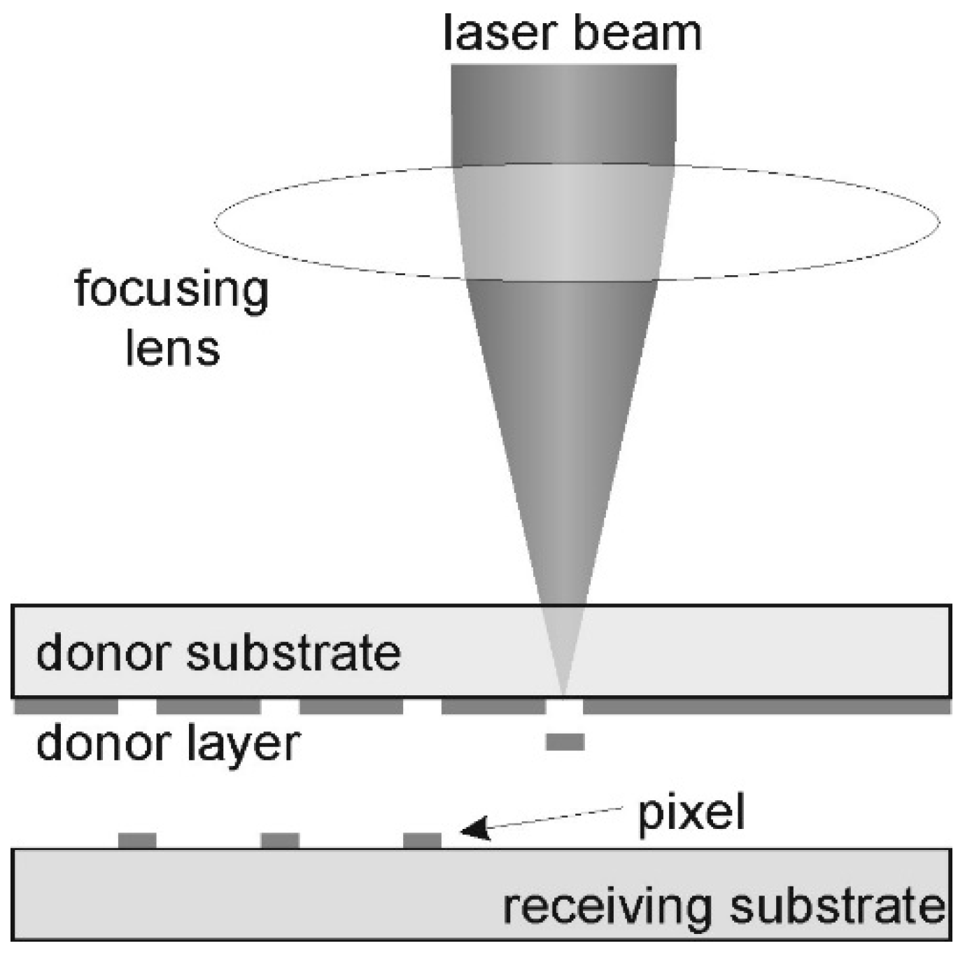
2. Experimental Setup

The main elements of a typical setup for LIFT printing are schematically represented in Figure 1. A laser beam is focused by a lens on the interface between the donor substrate and the donor layer. For this, the donor substrate must be transparent at the laser wavelength and must be pre-coated with a layer of the material or ink that wants to be printed. Part of the donor layer is ejected by the action of the focused laser and is deposited on the receiving substrate that is placed in front of the donor layer. Patterns can be printed by depositing pixels on the desired positions by scanning the laser beam and/or by moving the donor and receiving substrates.
Most frequently, the laser sources used for LIFT are pulsed laser systems with pulses of several nanoseconds; although, ultrafast laser systems with picosecond and femtosecond pulses can also be used [20,24]. Good pulse to pulse stability guarantees reproducibility of the printed outcomes. With the aim to reduce costs, continuous wave (CW) lasers have also been demonstrated able to print conductive inks by LIFT [25,26,27]. In general, the laser wavelength does not play a key role in the process. However, it must match with the transparency of the donor substrate and the absorption ability of the donor layer. The laser beam is modified, directed, and focused to the donor substrate–donor layer interface by means of optical elements like mirror, beamsplitters, and lenses. The use of power- and energy-meters is highly recommended for a good control of the laser pulse energy.
As said above, the donor substrate must be transparent to the laser wavelength. Thus, glass materials can be used for near-infrared and visible lasers. UV laser wavelengths require more expensive options like quartz or fused silica. Other materials compatible with roll-to-roll processes like PET or other polymers can be used as long as the laser beam can go through them. A thin layer of the ink must be uniformly extended on the rear surface of the donor substrate. This is usually done by spin-coating or blade-coating at laboratory scale. This process can be automatized with continuous ink feeding for roll-to-roll production [28]. The ink must have at least one component that absorbs the laser radiation. Otherwise, either non-linear absorption must be promoted by using femtosecond laser pulses or a thin absorbing layer must be placed between the donor substrate and the ink layer [29,30]. This intermediate layer, also known as sacrificial layer, can be a metallic thin film of some tens of nanometers or a thicker polymeric layer that decomposes during transfer to minimize contamination.
The receiving substrate is placed parallel in front of the donor ink layer. A minimum gap of some tenths of microns are required to prevent wetting issues. For inks with Newtonian behavior, the gap is not a relevant parameter and uniform printings can be obtained for separations distances of few millimeters [31,32,33], easily achievable in roll-to-roll systems. However, printing of non-Newtonian inks requires a higher control of this gap [34,35]. In order to produce patterns, scanners with galvanometric mirrors can be used to raster the laser beam along the donor layer. Alternatively, the donor and receiving substrates can be moved by motion stages synchronously with the laser repetition rate.

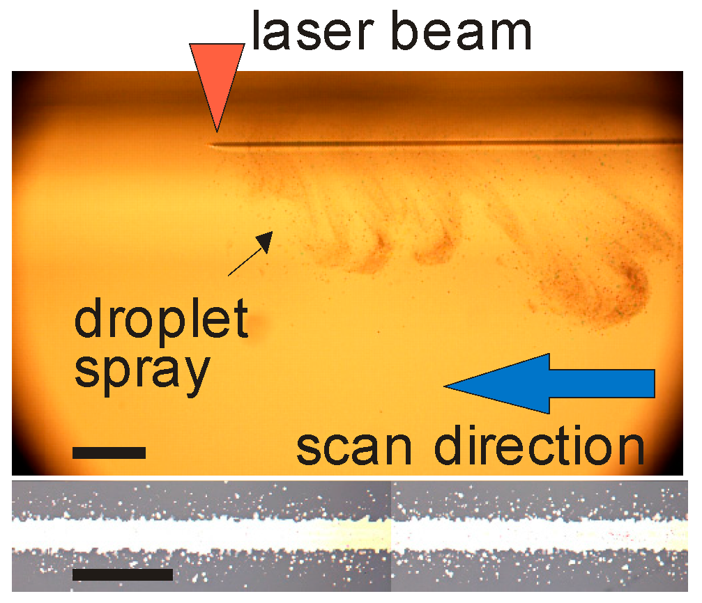
3. Ejection Mechanisms

The ejection dynamics of inks driven by LIFT have been studied by fast-imaging acquisition, usually through stop-action movies [34,36,37,38,39,40,41,42,43,44,45,46,47,48,49,50,51,52,53,54,55,56]. Temporal resolutions below 100 ns are required owing to the fast dynamics of the events involved, especially during the first microseconds. Images of ink ejection at different delay times after the laser pulse at different laser fluences are shown in Figure 2. The ejection of material from the donor layer is triggered by the absorption of the laser radiation at the interface between the donor substrate and the ink layer. As a result of the steep increase of the temperature a tiny vapor bubble at high pressure is generated. The expansion of the bubble inside the ink is not isotropic owing to the presence of the rigid donor substrate. Thus, the bubble walls expand by pushing the liquid laterally and towards the free surface of the ink layer. Consequently, a gradient of pressure appears in the ink around the bubble going from its sides to its pole facing the free surface of the ink layer. Owing to the pressure gradient, the liquid surrounding the bubble flows towards the pole where all the streams converge and increase the pressure at this point. The high-pressure accumulation at the pole is finally released by ejecting two jets moving in opposite directions. The first one propagates forward away from the donor layer and will lead to ink deposition, and the second one moves backwards to the donor substrate through the bubble. The bubble starts collapsing when the pressure outside is higher than inside, but the first jet continues moving forward towards the receiving substrate. This jetting dynamics is very similar to that found for an expanding bubble near the free surface of a liquid and can be simulated numerically using fluid mechanics equations [57,58]. Jets are stable under certain laser parameters that depend on the rheological properties of the ink and thickness of the donor layer. Jets move forward at fast speed (up to hundreds of m/s) and can last several hundreds of μs before Plateau–Rayleigh instabilities appear for breaking the jet (Figure 2b,c). Jets can be several millimeters long before breaking.
When the laser fluence is just below the threshold for getting transfer jets can also be formed, but impulsion is not enough to reach the receiving substrate and they recoil with bubble collapse (Figure 2a). On the contrary, when the laser fluence is too high, the bubble explodes as the pressure inside the bubble exceeds surface tension forces leading to the ejection of material in the form of a burst or plume (Figure 2d) [37,47]. The viscosity of the ink plays a key role in the formation and stability of the jet [54]. Stable jets are much easily produced in a wider range of fluences as viscosity increases [43]. In this sense, several studies have shown that jet formation and stability is mainly related with the Ohnesorge dimensionless number that relates the viscous forces with the inertial and surface tension forces [45,49,54,55,56].
A completely different mechanism occurs when operating LIFT with CW lasers. In this case, laser absorption produces a myriad of bubbles in the irradiated donor layer instead of a single one due to the longer interaction times in CW-LIFT compared to LIFT with pulsed lasers. The burst of the bubbles generated produces the ejection of tiny droplets of the ink. The continuous burst of bubbles generates perturbations in the free surface of the ink layer. Consequently, the bubbles are ejected in multiple directions like a spray (Figure 3) [26].

4. Printing Results

Ejected material by the mechanisms reported above can be collected on any substrate placed in front of the donor layer of ink. The simplest output result is a single droplet that corresponds to a pixel of deposited material when the ink dries.

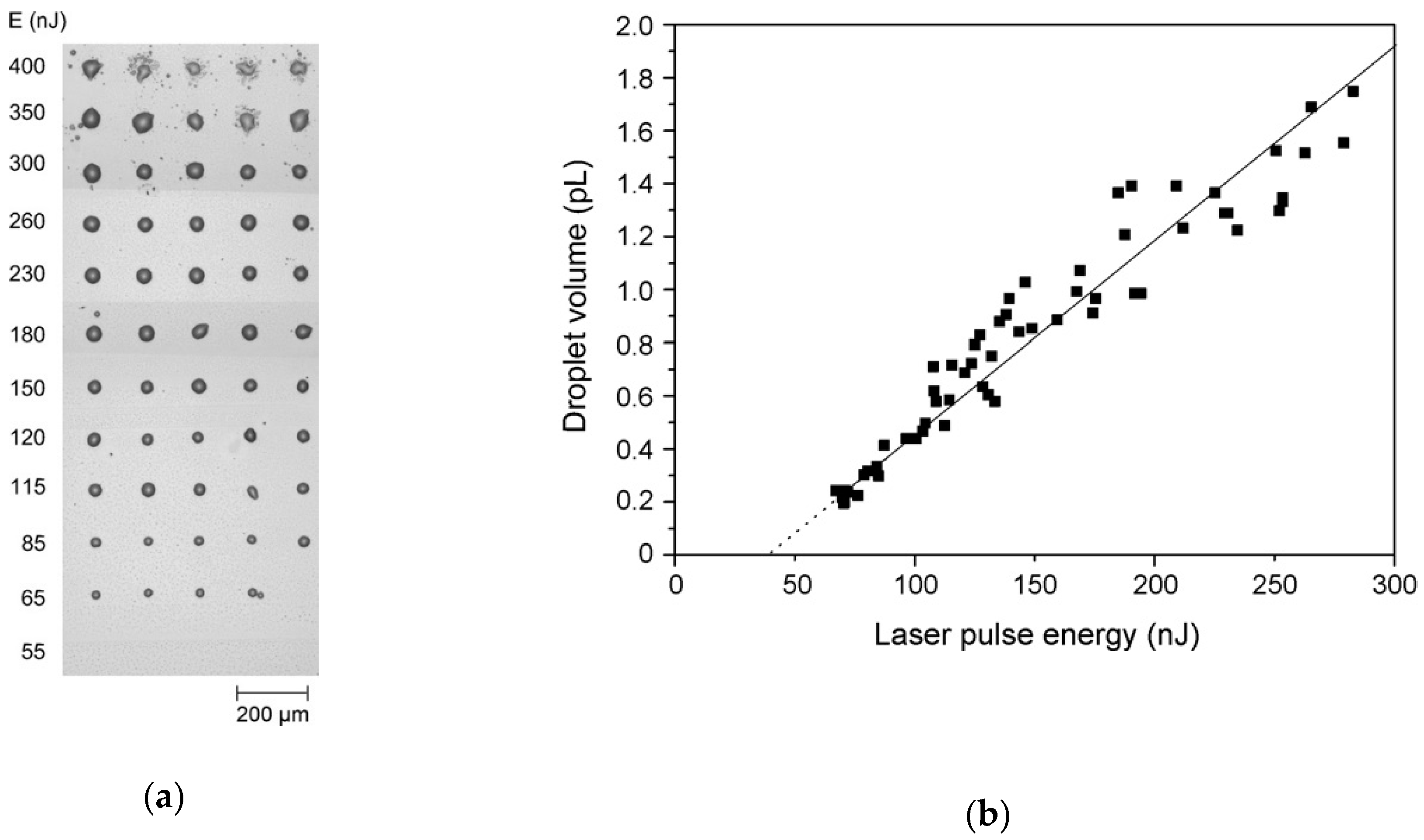
4.1. Droplet Printing

Reproducible sessile droplet printing through LIFT has already been demonstrated in the first studies appearing in bibliography [59,60]. Despite the high speed of the jet advancing to the receiving substrate, the deposition of the ink from long and stable jets is gentle enough to print circular droplets of delicate materials [61]. The size of the pixels can be controlled by adjusting the laser beam size and pulse energy [61,62]. For instance, under optimized conditions and at fluences just above the threshold for material ejection, droplets with diameters below 10 μm of a protein solution were printed [31]. However, final droplet diameter size is also determined by the rest of parameters involved in the LIFT process. Among them, the wetting properties of the ink on the receiving substrate are especially determinant for the final size of the printed pixels. For this reason, the volume transferred is a more independent parameter when comparing results between different experiments. In spite of the complex jetting ejection dynamic explained in Section 3, several studies show a linear relationship between the volume of the printed droplets and the energy of the laser pulse (Figure 4) [31,33,37,41,42,44,61,62,63,64]. Most of these studies were conducted with water-based inks. However, this is not a universal rule. For instance, completely different behaviors were found with Ag nanoparticle inks [65,66,67]. In all cases, the laser pulse must overcome a certain threshold energy to get material transfer. Uniform and circular droplets with minimum size are printed with pulse energies just above this threshold (Figure 4a). The volume, and consequently the diameter, of the printed pixels increases with increasing pulse energy. However, an excess of pulse energy is accompanied by irregularities in the droplet contour and/or splashing and small satellites. This trend agrees with the different ejection mechanisms described in Section 3. For low pulse energy, droplets are formed by contact of the jet with the substrate. The jet gently feeds the ink on the receiving substrate making the droplet grow until breakup. As the pulse energy increases, the jet gets higher speeds and impulsion. Consequently, a higher amount of ink is transferred into the substrate for getting larger droplets. As the speed gets faster the flow regime becomes turbulent causing irregularities in the droplet shape. Finally, if the pulse energy is high enough to provoke bubble burst, the ink is collected on the substrate as a splash.
Printing in the jet regime has not only the advantage of transferring the smallest volumes, but also that the printing outcomes are quite independent of the donor–receiver gap [33,38,63]. However, when this gap is narrower than the maximum height of the expanding bubble, the ejected ink reaches the receiving substrate before the jet can be formed. In this case, the transfer occurs by direct contact of the bubble. Despite the different mechanism involved, printed volumes are similar to those transferred with higher gaps and jet formation when using the same pulse energy. However, differences appear in the printed outcomes because of the different speed of the ink when contacting the substrate [63]. The higher speed in the bubble contact mode favors a higher contact angle of the ink with the substrate which leads to larger droplet diameters. However, printing in this “high-speed regime” allows the printing of inks on superhydrophobic surfaces [46]. For non-Newtonian inks with high solid content and high viscosity, like some conductive screen-printing inks, jet formation does not occur, and transfer can only be achieved through bubble contact [34]. In this case, the gap between the donor layer and the receiving substrate is determinant for the total volume transferred and the printed droplet characteristics. Surprisingly, the deposited volume also follows a linear trend with pulse energy for the conductive screen-printing ink used by Sopeña et al. [34].
The spraying ejection dynamic observed for CW lasers when scanning the laser beam on the donor layer would not seem adequate for printing single pixels [26]. However, isolated pixels of bioinks have been successfully printed in a recent study by using an absorbing layer and controlling the power and exposure time [68]. In view of the long exposure times required, the printing speed of isolated pixels is hindered. However, use of CW lasers can lead to the implementation of affordable LIFT systems.

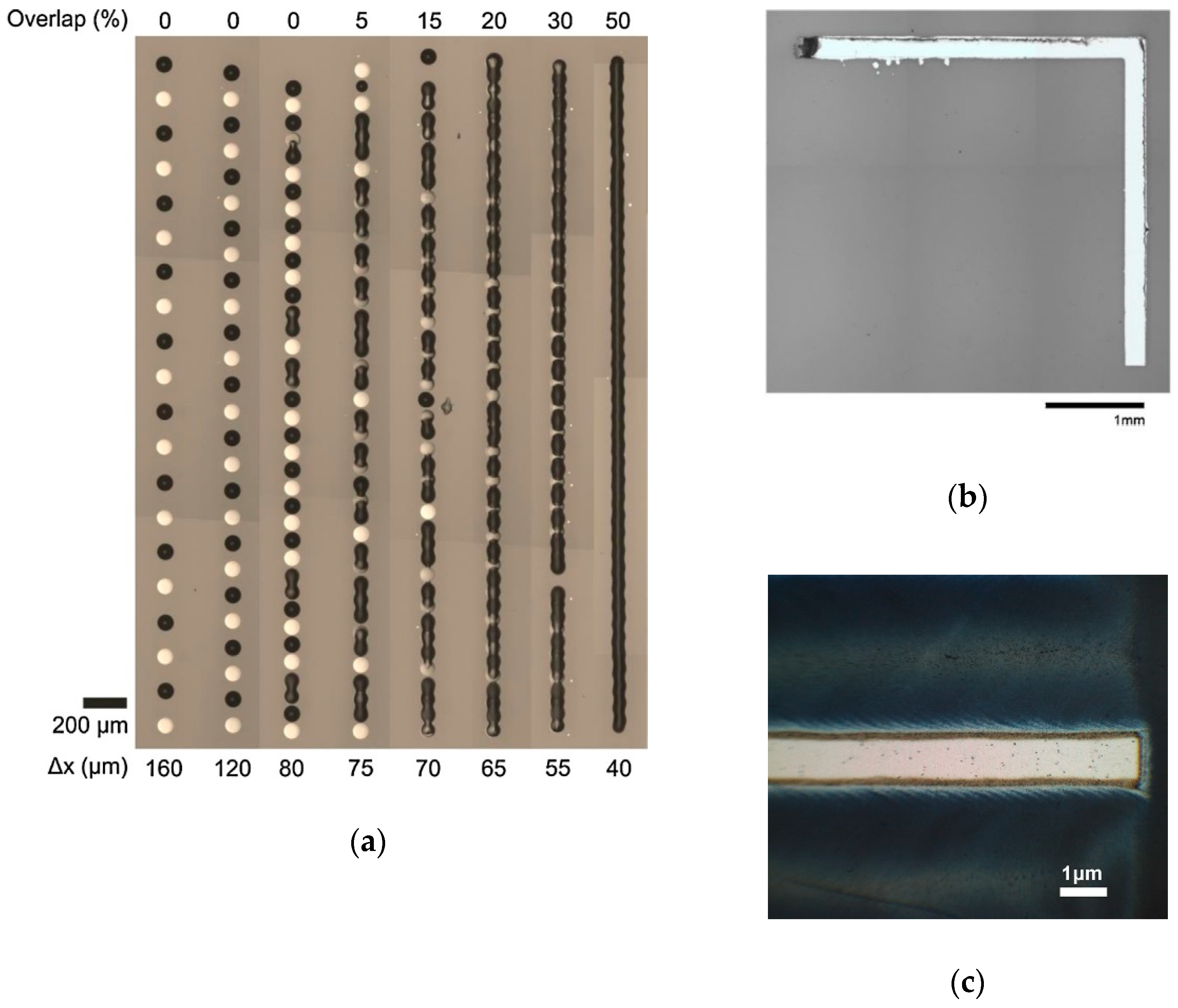
4.2. Continuous Patterns

The step of constructing patterns from the addition of single droplets to the required positions would seem straightforward. This can be done by the simple movement of the donor and receiving substrates, by scanning the laser beam along the donor layer or by a synchronized combination of both. However, some constraints appear when the patterns must keep continuity. This is a general issue for any printing technique dealing with fluid inks [69,70]. Printed droplets must overlap and adequately coalesce to generate the chosen design. Unfortunately, a universal solution does not exist. The outcome is mainly influenced by the specific properties of the ink and the substrate. This issue is especially relevant in the printing of conductive tracks for electronic applications. Any defect, like a single discontinuity or any protuberance, compromises the performance of the full device. Accordingly, conductive inks are mainly involved in most of the LIFT studies dealing with the printing of continuous patterns [35,65,66,71,72,73,74,75,76,77,78]. Nevertheless, studies on continuous line and homogeneous area printing have been also conducted with water-based suspensions in view of their interest in biosensors fabrication [79,80].
Printing continuous lines requires a specific study for every combination of ink and substrate. Some overlap between neighbor pixels is always required. When the overlap is too small the contour of the printed line appears scalloped due to capillary flows between the ink being fed by the jet and the already deposited ink [79]. When the overlap is too high, bulges appear all along the line because of liquid accumulation and backward capillary flows. Whenever the printing of continuous lines without irregularities is possible, the window of possible overlaps for success is narrow in general. Hence, some strategies have been tried to overcome the inherent difficulties of printing regular continuous lines. One of them proposes the separate printing of two sets of pixels [72]. Each set is formed by non-overlapping droplets, but the ensemble of both sets overlaps to get the required continuity (Figure 5a). This strategy requires an intermediate drying step of the first set before the second one can be printed. Thus, this intermediate step is detrimental for the production yield and adds elements in the production line. A different strategy proposes directly transferring the ink on fluidic guides that confine the liquid inside their walls and, therefore, prevent bulge formation [75]. In this case, the previous production of the guides on the substrate is an additional step. However, sharp angles and complicated geometries can be easily obtained through this method that would otherwise be difficult to attain (Figure 5b). This strategy is not only valid for LIFT, but quite universal for any ink printing method. However, lasers are versatile tools that can be used for both tasks; first for fluidic guide production in ablation mode, and afterwards for ink deposition in LIFT mode. Additionally, the laser can be used also for the selective sintering of the deposited material [73,81]. The ability for ablation of lasers can also be used after deposition for removing printing defects or narrow the line width. In this way, conductive lines with a width of 1 μm have been made following the final ablation strategy (Figure 5c) [73].

5. Printing of Functional Materials

LIFT has been demonstrated a valid digital printing technique capable of transferring a wide range of materials with micrometric resolution and almost no restrictions in the ink properties. The ejection from extended donor layers, and therefore nozzle-free, gives LIFT the ability to print inks with high solid content and large particles that would lead to clogging issues in other direct-write techniques. Moreover, very delicate materials like DNA [82] or cells [48] have been printed preserving their properties despite the fast ejection speeds involved. These good characteristics of LIFT have devised applications in fields as diverse as sensing, tissue engineering, or printed electronics.

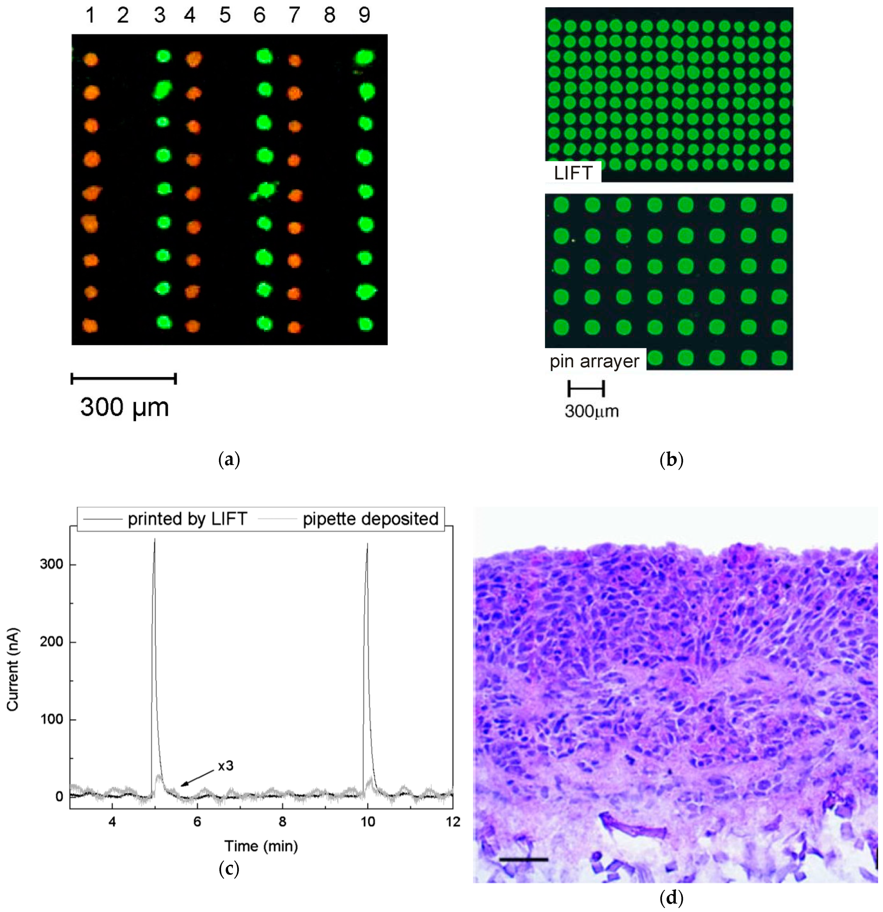
5.1. Biomolecule Microarrays and Sensors

In addition to their biologic relevance, biomolecules are highly selective sensing agents for detection. Thus, they are the main component of microarray devices, biosensors, and other chemical sensors. In general, biomolecules are sensible to small temperature variations as they change their original structure and, consequently, they lose their sensing properties.
DNA strands have been successfully printed by LIFT in microarrays [64,82,83]. Hybridization tests with complementary strands were performed to demonstrate the ability of the LIFT printed microarrays to discriminate between different genes (Figure 6a). Similar quantitative results were found when comparing LIFT printed microarrays with equivalent microarrays printed through standard pin microspotting machines (Figure 6b). Consequently, LIFT has equivalent results to that of other conventional techniques. Furthermore, LIFT offers the possibility to print pixels at higher resolution, which is beneficial from the point of view of waste reduction and packing the great amount of data that can be obtained from a single microarray. DNA oligonucleotides have been also printed by LIFT to produce micromembrane array capacitive biosensors [84].
Printing small volumes of proteins allows the production of biosensors for clinical diagnostics, defense, drug detection, or food and environment control. The printing of protein patterns is also being used for cell-growth studies and tissue engineering. With these objectives, LIFT experiments have confirmed its capability for printing many proteins without damaging their structure and ability for detection. The first proteins successfully printed by LIFT from liquid solution were bovine serum albumin (BSA) and anti-BSA [59]. After that, other proteins of any size were successfully printed, from small fragments of amino acids like peptides [85,86] to the large titin protein [32]. Thus, LIFT has proven the feasibility for printing antigens [60], immunoglobulins [61,64], enzymes [87], and horseradish peroxidase [88], among others.
Liposomes are big biological structures with application in sensing and drug delivery. With diameters of tens of micrometers, they cannot be easily printed by other direct-write techniques. Nevertheless, they can be easily printed through LIFT without damaging its delicate structure [89]. Thylakoid membranes have been also transferred on gold electrodes for biomolecule immobilization [90]. This experiment also demonstrated the advantages of using LIFT in front of other printing techniques. The high energetic jet transporting the ink favors the complete wetting of the receiving surface and improving the immobilization of the transferred material. In this way, sensors benefit of higher sensitivities when the sensing material is deposited by LIFT (Figure 6c). In a similar way, bio-electronic artificial noses have been obtained by printing odorant-binding proteins on the surface of acoustic wave resonators [80,91].

5.2. Cells and Tissue Engineering

The printing of cells is an active field of research with increasing interest in the last decade. It receives the name of bioprinting and faces the challenge of assembling cells to mimic the natural cell environment for regenerative medicine and in vitro cell behavior studies. LIFT meets all the conditions to succeed in this challenge [92,93]. The absence of a nozzle eliminates clogging issues, existing in other used techniques like inkjet and extrusion printers, and it reduces shear-induced stresses detrimental for the cell survival rate. Furthermore, it has no restrictions for printing typical bioinks of high viscosity with cells of micrometric size, without sacrificing resolution.
The first reported cells printed by LIFT were Chinese hamster ovaries eukaryotic cells [94]. The versatility and precision of LIFT allows the printing from single cells [95] to multicellular organisms [96], as well as patterns with high density of cells [97]. Many different types of cells like human osteosarcoma and mouse endothelial cells [98], Escherichia coli [99], aortic endothelial cells [100], mouse fibroblast cells [101], neuronal cells [102], or stem cells [103,104] among many others [92], have been printed through LIFT.
LIFT has the capability of printing combination of cells with proteins and other biological compounds with enough resolution to simulate the complexity of living tissues [105,106,107]. This allows in vitro studies of cell interactions with other cells and their environment [107]. The possibilities for tissue engineering have been demonstrated by printing structures that mimic living tissues and promote vascularization [108]. Thus, artificial tissue structures have been printed for stimulating skin repair (Figure 6d) [109,110] or blood vessel generation [111,112]. All these advances attracted the interest of companies for commercializing LIFT for bioprinting. Poietis appeared in 2014 for manufacturing 3D human tissues models by LIFT for cosmetics and pharmaceutical laboratories [113]. The company also commercializes bioprinting platforms based on LIFT for R&D and clinical applications. Precise-Bio is also offering technology based on LIFT for bioprinting with improved resolution (1 μm) and cell viability (>95%) with respect other techniques such as inkjet or extrusion [114].

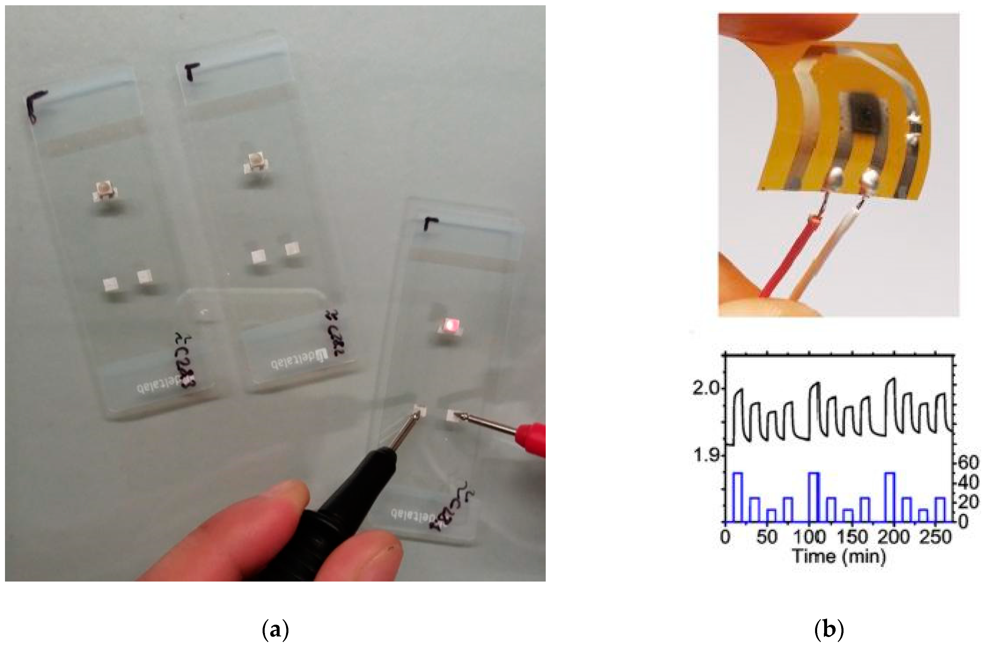
5.3. Printed Electronics

Together with bioprinting, printed electronics applications are attracting most of the actual studies dealing with LIFT. Printing technologies are boosting the production of small electronic devices that are more and more incorporated in our daily life [115]. RFID tags, sensors, antennas, solar cells, OLEDs are printed on flexible substrates like polymers, paper, or fabric at low cost. As seen in previous applications, LIFT characteristics let it be proposed as one of the best digital printing techniques for printed electronics, too. Among them, the wide range of printable ink viscosities, the possibility to print inks with large particles and its compatibility with roll-to-roll production makes LIFT the perfect direct-write substitute to actual printing technologies like screen-printing or rotogravure. In fact, the first works where LIFT was proposed already pointed the application of LIFT for printing conductive materials aiming electronic applications, first with solid donor films [3,6], and afterwards with inks [21,23].
Most of the attempts for producing conductive patterns use Ag nanoparticle inks. The ones with low solid content and low viscosity (few mPa·s) similar to those used for inkjet printers are easily printable through the jet ejection mechanism and lead to lines with the best resolution [65,66,67,72,73,74,75,76,116]. However, most of the commercial conductive circuits are still printed by screen-printing [115], because the high solid content of the ink results in sheet-resistance values two order of magnitude below those obtained with inkjet inks. As said before for cell printing, the high viscosity (some Pa·s) and large particles of these inks are not a limitation for LIFT [35,77,78,117,118].
The high production rates required to compete with mass production techniques like screen-printing lead to use high repetition rate lasers and fast scanning speeds. The spatial proximity of ejection events for getting continuous outcomes, together with the temporal proximity when printing at high-speed lead to the interaction of consecutive bubbles and jets that lead to unpredicted printing results [119,120]. By analyzing these interactions through time-resolved imaging, it was found that, under certain conditions, the jets can be linked for getting continuous lines at high repetition rate (1 MHz) and high speed (17 m/s) [74]. Recently, continuous lines have been printed even faster (60 m/s) [35].
Ag nanowires networks are substituting transparent conductive oxides in applications where materials with good electrical conductivity and optical transparency must be applied on flexible substrates [121]. The high aspect-ratio of these nanostructures are crucial for its good performance but poses printability limitations in nozzle-based printing techniques. Thus, LIFT appears as a good alternative for digitally printing Ag nanowires networks. As a proof-of-concept, conductive and transparent electrodes were printed on glass that resulted in being invisible to the naked eye (Figure 7a) [122]. Other long nanoparticles like carbon nanofibers have also been printed by LIFT for making gas sensors (Figure 7b) [25,116].
Although the number of studies is still limited, LIFT is not restricted to print only conductive materials. As a mode of example, LIFT have been found also adequate for printing semiconducting polymer inks for organic electronics applications [123]. Other composite polymers [124] and reduced graphene oxide [125] have been also printed by LIFT for gas sensor applications.
The good performance of LIFT for printing materials of electronic interest has also attracted the interest of the electronics industry. A consortium of companies and academia (HiperLAM) was founded by the Horizon 2020 research and innovation program of the European Union for demonstrating the benefits of laser-based additive manufacturing for printing radio frequency identification (RFID) antennas and laser fingerprinted sensors [126]. The leading company of this consortium, Orbotech Ltd. uses LIFT technology for repairing TV-displays and flexible OLED displays [127]. On the other hand, LPKF Laser & Electronics company is offering the laser transfer printing process based on LIFT for large area digital printing. Their printer systems demonstrate the scalability of LIFT for printing on large and curved surfaces with productivity rates up to 90 m2/h and resolution of 1200 dpi × 600 dpi [128].

6. Summary

LIFT is a laser direct-write technique that is being explored for printing inks since 1999. Its principle of operation is based on the action of a laser focused on a thin layer of ink to initiate the ejection process. Optimal printing results are obtained when the ink is transferred through jets that contact the receiving substrates. The amount of ink transferred can be controlled through the laser pulse energy and the beam size at the donor layer. Among its strengths are the capability for printing inks in a wide range of viscosities and including particles of any size. Furthermore, the deposition process is gentle enough to keep all the functionality of the printed materials. Hence, the viability of LIFT for printing biomolecules and cells has been largely demonstrated in many studies. LIFT has great potential for digitally printing any kind of material, being inorganic, organic, or living matter. At present, LIFT has found a niche of applications in the fields of bioprinting and printed electronics in which other direct-write techniques have limitations. Thus, it is in these fields were most of the actual research is centered. However, thanks to its great versatility, LIFT will surely be a key technology in other fields as new functional materials and new applications will be appearing.

Funding

This research was funded by AEI of the Spanish Government (Projects TEC2015-72425-EXP and TEC2017-83301-P) and by Fondo Europeo de Desarrollo Regional (FEDER).

Conflicts of Interest

The authors declare no conflict of interest.

References

  1. Piqué, A.; Chrisey, D.B. Direct-Write Technologies for Rapid Prototyping Applications, 1st ed.; Academic Press: San Diego, CA, USA, 2001. [Google Scholar]
  2. Hon, K.K.B.; Li, L.; Hutchings, I.M. Direct writing technology—Advances and developments. CIRP Ann. Manuf. Technol. 2008, 57, 601–620. [Google Scholar] [CrossRef]
  3. Brisbane, A.D. Method for Vapour Depositing a Material in the Form of a Pattern. Great. Britain Patent GB1,138,084, 27 December 1968. [Google Scholar]
  4. Braudy, R.S. Laser writing. Proc. IEEE 1969, 57, 1771–1772. [Google Scholar] [CrossRef]
  5. Levene, M.L.; Scott, R.D.; Siryj, B.W. Material transfer recording. Appl. Opt. 1970, 9, 2260–2265. [Google Scholar] [CrossRef] [PubMed]
  6. Bohandy, J.; Kim, B.F.; Adrian, F.J. Metal deposition from a supported metal film using an excimer laser. J. Appl. Phys. 1986, 60, 1538–1539. [Google Scholar] [CrossRef]
  7. Adrian, F.J.; Bohandy, J.; Kim, B.F.; Jette, A.N.; Thompson, P. A study of the mechanism of metal-deposition by the laser-induced forward transfer process. J. Vac. Sci. Technol. B 1987, 5, 1490–1494. [Google Scholar] [CrossRef]
  8. Mogyorósi, P.; Szörényi, T.; Bali, K.; Tóth, Z.; Hevesi, I. Pulsed laser ablative deposition of thin metal films. Appl. Surf. Sci. 1989, 36, 157–163. [Google Scholar] [CrossRef]
  9. Schultze, V.; Wagner, M. Laser-induced forward transfer of aluminum. Appl. Surf. Sci. 1991, 52, 303–309. [Google Scholar] [CrossRef]
  10. Kántor, Z.; Tóth, Z.; Szörényi, T. Laser induced forward transfer: The effect of support-film interface and film-to-substrate distance on transfer. Appl. Phys. A Mater. 1992, 54, 170–175. [Google Scholar] [CrossRef]
  11. Zergioti, I.; Mailis, S.; Vainos, N.A.; Fotakis, C.; Chen, S.; Grigoropoulos, C.P. Microdeposition of metals by femtosecond excimer laser. Appl. Surf. Sci. 1998, 127–129, 601–605. [Google Scholar] [CrossRef]
  12. Greer, J.A.; Parker, T.E. Laser-induced forward transfer of metal oxides to trim the frequency of surface acoustic wave resonator devices. SPIE Proc. 1988, 998, 113–125. [Google Scholar]
  13. Zergioti, I.; Mailis, S.; Vainos, N.A.; Papakonstantinou, P.; Kalpouzos, C.; Grigoropoulos, C.P.; Fotakis, C. Microdeposition of metal and oxide structures using ultrashort laser pulses. Appl. Phys. A Mater. 1998, 66, 579–582. [Google Scholar] [CrossRef]
  14. Papakonstantinou, P.; Vainos, N.A.; Fotakis, C. Microfabrication by UV femtosecond laser ablation of Pt, Cr and indium oxide thin films. Appl. Surf. Sci. 1999, 151, 159–170. [Google Scholar] [CrossRef]
  15. Fogarassy, E.; Fuchs, C.; Kerherve, F.; Hauchecorne, G.; Perriere, J. Laser-induced forward transfer of high-Tc YBaCuO and BiSrCaCuO superconducting thin films. J. Appl. Phys. 1989, 66, 457–459. [Google Scholar] [CrossRef]
  16. Zenou, M.; Sa’ar, A.; Kotler, Z. Laser jetting of femto-liter metal droplets for high resolution 3D printed structures. Sci. Rep. 2015, 5, 17265. [Google Scholar] [CrossRef]
  17. Visser, C.W.; Pohl, R.; Sun, C.; Huis in’t Veld, B.; Römer, G.W.; Lohse, D. Toward 3D printing of pure metals by laser-induced forward transfer. Adv. Mater. 2015, 27, 4087–4092. [Google Scholar] [CrossRef] [Green Version]
  18. Li, G.; Mo, X.; Law, W.-C.; Chan, K.C. 3D printed graphene/nickel electrodes for high areal capacitance electrochemical storage. J. Mater. Chem. A 2019, 7, 4055–4062. [Google Scholar] [CrossRef]
  19. Delaporte, P.; Alloncle, A.-P. Laser-induced forward transfer: A high resolution additive manufacturing technology. Opt. Laser Technol. 2016, 78, 33–41. [Google Scholar] [CrossRef]
  20. Serra, P.; Piqué, A. Laser-induced forward transfer: Fundamentals and applications. Adv. Mater. Technol. 2019, 4, 1800099. [Google Scholar] [CrossRef] [Green Version]
  21. Piqué, A.; Chrisey, D.B.; Auyeung, R.C.Y.; Fitz-Gerald, J.; Wu, H.D.; McGill, R.A.; Lakeou, S.; Wu, P.K.; Nguyen, V.; Duignan, M. A novel laser transfer process for direct writing of electronic and sensor materials. Appl. Phys. A Mater. 1999, 69, S279–S284. [Google Scholar] [CrossRef]
  22. Piqué, A.; McGill, R.A.; Chrisey, D.B.; Leonhardt, D.; Mslna, T.E.; Spargo, B.J.; Callahan, J.H.; Vachet, R.W.; Chung, R.; Bucaro, M.A. Growth of organic thin films by the matrix assisted pulsed laser evaporation (MAPLE) technique. Thin Solid Films 1999, 355–356, 536–541. [Google Scholar] [CrossRef]
  23. Piqué, A.; Fitz-Gerald, J.; Chrisey, D.B.; Auyeung, R.C.Y.; Wu, H.D.; Lakeou, S.; McGill, R.A. Direct writing of electronic materials using a new laser assisted transfer/annealing technique. Proc. SPIE 2000, 3933, 105–112. [Google Scholar]
  24. Fernández-Pradas, J.M.; Florian, C.; Caballero-Lucas, F.; Sopeña, P.; Morenza, J.L.; Serra, P. Laser-induced forward transfer: Propelling liquids with light. Appl. Surf. Sci. 2017, 418, 559–564. [Google Scholar] [CrossRef]
  25. Sopeña, P.; Arrese, J.; González-Torres, S.; Fernández-Pradas, J.M.; Cirera, A.; Serra, P. Low-cost fabrication of printed electronics devices through continuous wave laser-induced forward transfer. ACS Appl. Mater. Interfaces 2017, 9, 29412–29417. [Google Scholar] [CrossRef] [PubMed]
  26. Sopeña, P.; González-Torres, S.; Fernández-Pradas, J.M.; Serra, P. Spraying dynamics in continuous wave laser printing of conductive inks. Sci. Rep. 2018, 8, 7999. [Google Scholar] [CrossRef] [PubMed]
  27. Lim, J.; Kim, Y.; Shin, J.; Lee, Y.; Shin, W.; Qu, W.; Hwang, E.; Park, S.; Hong, S. Continuous-Wave Laser-Induced Transfer of Metal Nanoparticles to Arbitrary Polymer Substrates. Nanomaterials 2020, 10, 701. [Google Scholar] [CrossRef] [Green Version]
  28. Hennig, G.; Baldermann, T.; Nussbaum, C.; Rossier, M.; Brockelt, A.; Schuler, L.; Hochstein, G. Lasersonic® LIFT process for large area digital printing. J. Laser Micro/Nanoeng. 2012, 7, 299–305. [Google Scholar] [CrossRef]
  29. Fernández-Pradas, J.M.; Colina, M.; Serra, P.; Domínguez, J.; Morenza, J.L. Laser-induced forward transfer of biomolecules. Thin Solid Films 2004, 453–454, 27–30. [Google Scholar] [CrossRef]
  30. Kattamis, N.T.; McDaniel, N.D.; Bernhard, S.; Arnold, C.B. Laser direct write printing of sensitive and robust light emitting organic molecules. Appl. Phys. Lett. 2009, 94, 103306. [Google Scholar] [CrossRef] [Green Version]
  31. Duocastella, M.; Colina, M.; Fernández-Pradas, J.M.; Serra, P.; Morenza, J.L. Study of the laser-induced forward transfer of liquids for laser bioprinting. Appl. Surf. Sci. 2007, 253, 7855–7859. [Google Scholar] [CrossRef]
  32. Dinca, V.; Ranella, A.; Farsari, M.; Kafetzopoulos, D.; Dinescu, M.; Popescu, A.; Fotakis, C. Quantification of the activity of biomolecules in microarrays obtained by direct laser transfer. Biomed. Microdevices 2008, 10, 719–725. [Google Scholar] [CrossRef]
  33. Serra, P.; Duocastella, M.; Fernández-Pradas, J.M.; Morenza, J.L. Liquids microprinting through laser induced forward transfer. Appl. Surf. Sci. 2009, 255, 5342–5345. [Google Scholar] [CrossRef]
  34. Sopeña, P.; Fernández-Pradas, J.M.; Serra, P. Laser-induced forward transfer of conductive screen-printing inks. Appl. Surf. Sci. 2020, 507, 145047. [Google Scholar] [CrossRef]
  35. Munoz-Martin, D.; Chen, Y.; Morales, M.; Molpeceres, C. Overlapping Limitations for ps-Pulsed LIFT Printing of High Viscosity Metallic Pastes. Metals 2020, 10, 168. [Google Scholar] [CrossRef] [Green Version]
  36. Duocastella, M.; Fernández Pradas, J.M.; Serra, P.; Morenza, J.L. Jet formation in the laser forward transfer of liquids. Appl. Phys. A Mater. 2008, 93, 453–456. [Google Scholar] [CrossRef]
  37. Duocastella, M.; Fernández-Pradas, J.M.; Morenza, J.L.; Serra, P. Time-resolved imaging of the laser forward transfer of liquids. J. Appl. Phys. 2009, 106, 084907. [Google Scholar] [CrossRef] [Green Version]
  38. Duocastella, M.; Fernández-Pradas, J.M.; Morenza, J.L.; Serra, P. Sessile droplet formation in the laser-induced forward transfer of liquids: A time-resolved imaging study. Thin Solid Films 2010, 518, 5321–5325. [Google Scholar] [CrossRef]
  39. Unger, C.; Gruene, M.; Koch, L.; Koch, J.; Chichkov, B.N. Time-resolved imaging of hydrogel printing via laser-induced forward transfer. Appl. Phys. A Mater. 2011, 103, 271–277. [Google Scholar] [CrossRef]
  40. Brown, M.; Kattamis, N.; Arnold, C. Time-resolved dynamics of laser-induced micro-jets from thin liquid films. Microfluid. Nanofluids 2011, 11, 199–207. [Google Scholar] [CrossRef]
  41. Gruene, M.; Unger, C.; Koch, L.; Deiwick, A.; Chichkov, B.N. Dispensing pico to nanolitre of a natural hydrogel by laser-assisted bioprinting. Biomed. Eng. Online 2011, 10, 19. [Google Scholar] [CrossRef] [Green Version]
  42. Duocastella, M.; Patrascioiu, A.; Dinca, V.; Fernández-Pradas, J.M.; Morenza, J.L.; Serra, P. Study of liquid deposition during laser printing of liquids. Appl. Surf. Sci. 2011, 257, 5255–5258. [Google Scholar] [CrossRef]
  43. Dinca, V.; Patrascioiu, A.; Fernández-Pradas, J.M.; Morenza, J.L.; Serra, P. Influence of solution properties in the laser forward transfer of liquids. Appl. Surf. Sci. 2012, 258, 9379–9384. [Google Scholar] [CrossRef]
  44. Duocastella, M.; Patrascioiu, A.; Fernández-Pradas, J.M.; Morenza, J.L.; Serra, P. On the correlation between droplet volume and irradiation conditions in the laser forward transfer of liquids. Appl. Phys. A Mater. 2012, 109, 5–14. [Google Scholar] [CrossRef]
  45. Yan, J.; Huang, Y.; Xu, C.; Chrisey, D.B. Effects of fluid properties and laser fluence on jet formation during laser direct writing of glycerol solution. J. Appl. Phys. 2012, 112, 083105. [Google Scholar] [CrossRef]
  46. Boutopoulos, C.; Papageorgiou, D.P.; Zergioti, I.; Papathanasiou, A.G. Sticking of droplets on slippery superhydrophobic surfaces by laser induced forward transfer. Appl. Phys. Lett. 2013, 103, 024104. [Google Scholar] [CrossRef]
  47. Boutopoulos, C.; Kalpyris, I.; Serpetzoglou, E.; Zergioti, I. Laser-induced forward transfer of silver nanoparticle ink: Time-resolved imaging of the jetting dynamics and correlation with the printing quality. Microfluid. Nanofluids 2014, 16, 493–500. [Google Scholar] [CrossRef]
  48. Ali, M.; Pages, E.; Ducom, A.; Fontaine, A.; Guillemot, F. Controlling laser-induced jet formation for bioprinting mesenchymal stem cells with high viability and high resolution. Biofabrication 2014, 6, 045001. [Google Scholar] [CrossRef]
  49. Zhang, Z.; Xiong, R.; Mei, R.; Huang, Y.; Chrisey, D.B. Time-resolved imaging study of jetting dynamics during laser printing of viscoelastic alginate solutions. Langmuir 2015, 31, 6447–6456. [Google Scholar] [CrossRef]
  50. Zhang, Z.; Xiong, R.; Corr, D.T.; Huang, Y. Study of impingement types and printing quality during laser printing of viscoelastic alginate solutions. Langmuir 2016, 32, 3004–3014. [Google Scholar] [CrossRef]
  51. Turkoz, E.; Deike, L.; Arnold, C.B. Comparison of jets from Newtonian and non-Newtonian fluids induced by blister-actuated laser-induced forward transfer (BA-LIFT). Appl. Phys. A Mater. 2017, 123, 652. [Google Scholar] [CrossRef]
  52. Kalaitzis, A.; Makrygianni, M.; Theodorakos, I.; Hatziapostolou, A.; Melamed, S.; Kabla, A.; de la Vega, F.; Zergioti, I. Jetting dynamics of Newtonian and non-Newtonian fluids via laser-induced forward transfer: Experimental and simulation studies. Appl. Surf. Sci. 2019, 465, 136–142. [Google Scholar] [CrossRef]
  53. Mikšys, J.; Arutinov, G.; Römer, G.R.B.E. Pico- to nanosecond pulsed laser-induced forward transfer (LIFT) of silver nanoparticle inks: A comparative study. Appl. Phys. A Mater. 2019, 125, 814. [Google Scholar] [CrossRef] [Green Version]
  54. Jalaal, M.; Schaarsberg, M.K.; Visser, C.-W.; Lohse, D. Laser-induced forward transfer of viscoplastic fluids. J. Fluid Mech. 2019, 880, 497–513. [Google Scholar] [CrossRef] [Green Version]
  55. Turkoz, E.; Perazzo, A.; Deike, L.; Stone, H.A.; Arnold, C.B. Deposition-on-contact regime and the effect of donor-acceptor distance during laser-induced forward transfer of viscoelastic liquids. Opt. Mater. Express 2019, 9, 2738–2747. [Google Scholar] [CrossRef]
  56. Theodorakos, I.; Kalaitzis, A.; Makrygianni, M.; Hatziapostolou, A.; Kabla, A.; Melamed, S.; de la Vega, F.; Zergioti, I. Laser-induced forward transfer of high viscous, non-Newtonian silver nanoparticle inks:jet dynamics and temporal evolution of the printed droplet study. Adv. Eng. Mater. 2019, 21, 1900605. [Google Scholar] [CrossRef] [Green Version]
  57. Robinson, P.B.; Blake, J.R.; Kodama, T.; Shima, A.; Tomita, Y. Interaction of cavitation bubbles with a free surface. J. Appl. Phys. 2001, 89, 8225–8237. [Google Scholar] [CrossRef]
  58. Pearson, A.; Cox, E.; Blake, J.R.; Otto, S.R. Bubble interactions near a free surface. Eng. Anal. Bound. Elem. 2004, 28, 295–313. [Google Scholar] [CrossRef]
  59. Ringeisen, B.R.; Wu, P.K.; Kim, H.; Piqué, A.; Auyeung, R.Y.C.; Young, H.D.; Chrisey, D.B.; Krizman, D.B. Picoliter-scale protein microarrays by laser direct write. Biotechnol. Prog. 2002, 18, 1126–1129. [Google Scholar] [CrossRef]
  60. Serra, P.; Fernández Pradas, J.M.; Berthet, F.X.; Colina, M.; Elvira, J.; Morenza, J.L. Laser direct writing of biomolecule microarrays. Appl. Phys. A Mater. 2004, 79, 949–952. [Google Scholar] [CrossRef]
  61. Duocastella, M.; Fernández-Pradas, J.M.; Domínguez, J.; Serra, P.; Morenza, J.L. Printing biological solutions through laser-induced forward transfer. Appl. Phys. A Mater. 2008, 93, 941–945. [Google Scholar] [CrossRef]
  62. Colina, M.; Duocastella, M.; Fernández-Pradas, J.M.; Serra, P.; Morenza, J.L. Laser-induced forward transfer of liquids: Study of the droplet ejection process. J. Appl. Phys. 2006, 99, 084909. [Google Scholar] [CrossRef] [Green Version]
  63. Duocastella, M.; Fernández-Pradas, J.M.; Morenza, J.L.; Serra, P. Droplet printing through bubble contact in the laser forward transfer of liquids. Appl. Surf. Sci. 2011, 257, 2825–2829. [Google Scholar] [CrossRef]
  64. Fernández Pradas, J.M.; Duocastella, M.; Colina, M.; Serra, P.; Morenza, J.L. Production of miniaturized biosensors through laser-induced forward transfer. Proc. SPIE 2007, 6592, 65920R. [Google Scholar]
  65. Rapp, L.; Ailuno, J.; Alloncle, A.P.; Delaporte, P. Pulsed-laser printing of silver nanoparticles ink: Control of morphological properties. Opt. Express 2011, 19, 21563–21574. [Google Scholar] [CrossRef] [PubMed]
  66. Makrygianni, M.; Kalpyris, I.; Boutopoulos, C.; Zergioti, I. Laser induced forward transfer of Ag nanoparticles ink deposition and characterization. Appl. Surf. Sci. 2014, 297, 40–44. [Google Scholar] [CrossRef]
  67. Sopeña, P.; Fernández-Pradas, J.M.; Serra, P. Laser-induced forward transfer of low viscosity inks. Appl. Surf. Sci. 2017, 418, 530–535. [Google Scholar] [CrossRef]
  68. Huang, C.-F.; Colley, M.M.S.; Lu, L.-S.; Chang, C.-Y.; Peng, P.-W.; Yang, T.-S. Performance characterization of continuous-wave laser-induced forward transfer of liquid bioink. Appl. Phys. Express. 2019, 12, 116504. [Google Scholar] [CrossRef]
  69. Gau, H.; Herminghaus, S.; Lenz, P.; Lipowsky, R. Liquid morphologies on structured surfaces: From microchannels to microchips. Science 1999, 283, 46–49. [Google Scholar] [CrossRef] [Green Version]
  70. Stringer, J.; Derby, B. Formation and stability of lines produced by inkjet printing. Langmuir 2010, 26, 10365–10372. [Google Scholar] [CrossRef]
  71. Kim, H.; Auyeung, R.C.Y.; Lee, S.H.; Huston, A.L.; Piqué, A. Laser forward transfer of silver electrodes for organic thin-film transistors. Appl. Phys. A Mater. 2009, 96, 441–445. [Google Scholar] [CrossRef]
  72. Florian, C.; Caballero-Lucas, F.; Fernández-Pradas, J.M.; Artigas, R.; Ogier, S.; Karnakis, D.; Serra, P. Conductive silver ink printing through the laser-induced forward transfer technique. Appl. Surf. Sci. 2015, 336, 304–308. [Google Scholar] [CrossRef]
  73. Zacharatos, F.; Makrygianni, M.; Geremia, R.; Biver, E.; Karnakis, D.; Leyder, S.; Puerto, D.; Delaporte, P.; Zergioti, I. Laser Direct Write micro-fabrication of large area electronics on flexible substrates. Appl. Surf. Sci. 2016, 374, 117–123. [Google Scholar] [CrossRef]
  74. Puerto, D.; Biver, E.; Alloncle, A.-P.; Delaporte, P. Single step high-speed printing of continuous silver lines by laser-induced forward transfer. Appl. Surf. Sci. 2016, 374, 183–189. [Google Scholar] [CrossRef]
  75. Florian, C.; Caballero-Lucas, F.; Fernández-Pradas, J.M.; Ogier, S.; Winchester, L.; Karnakis, D.; Geremia, R.; Artigas, R.; Serra, P. Printing of silver conductive lines through laser-induced forward transfer. Appl. Surf. Sci. 2016, 374, 265–270. [Google Scholar] [CrossRef]
  76. Wang, X.; Xu, B.; Huang, Y.; Zhang, J.; Liu, Q. Laser-induced forward transfer of silver nanoparticle ink using burst technique. Appl. Phys. A Mater. 2019, 125, 845. [Google Scholar] [CrossRef]
  77. Tsakona, D.; Theodorakos, I.; Kalaitzis, A.; Zergioti, I. Investigation on high speed laser printing of silver nanoparticle inks on flexible substrates. Appl. Surf. Sci. 2020, 513, 145912. [Google Scholar] [CrossRef]
  78. Sopeña, P.; Sieiro, J.; Fernández-Pradas, J.M.; López-Villegas, J.M.; Serra, P. Laser-induced forward transfer: A digital approach for printing devices on regular paper. Adv. Mater. Technol. 2020, 5, 2000080. [Google Scholar] [CrossRef]
  79. Palla-Papavlu, A.; Córdoba, C.; Patrascioiu, A.; Fernández-Pradas, J.M.; Morenza, J.L.; Serra, P. Deposition and characterization of lines printed through laser-induced forward transfer. Appl. Phys. A Mater. 2013, 110, 751–755. [Google Scholar] [CrossRef] [Green Version]
  80. Palla-Papavlu, A.; Patrascioiu, A.; Di Pietrantonio, F.; Fernández-Pradas, J.M.; Cannatà, D.; Benetti, M.; D’Auria, S.; Verona, E.; Serra, P. Preparation of surface acoustic wave odor sensors by laser-induced forward transfer. Sens. Actuators B 2014, 192, 369–377. [Google Scholar] [CrossRef]
  81. Zacharatos, F.; Theodorakos, I.; Karvounis, P.; Tuohy, S.; Braz, N.; Melamed, S.; Kabla, A.; de la Vega, F.; Andritsos, K.; Hatziapostolou, A.; et al. Selective laser sintering of laser printed Ag nanoparticle micropatterns at high repetition rates. Materials 2018, 11, 2142. [Google Scholar] [CrossRef] [Green Version]
  82. Serra, P.; Colina, M.; Fernández Pradas, J.M.; Sevilla, L.; Morenza, J.L. Preparation of functional DNA microarrays through laser-induced forward transfer. Appl. Phys. Lett. 2004, 85, 1639–1641. [Google Scholar] [CrossRef] [Green Version]
  83. Colina, M.; Serra, P.; Fernández-Pradas, J.M.; Sevilla, L.; Morenza, J.L. DNA deposition through laser induced forward transfer. Biosens. Bioelectron. 2005, 20, 1638–1642. [Google Scholar] [CrossRef] [PubMed]
  84. Tsekenis, G.; Chatzipetrou, M.; Tanner, J.; Chatzandroulis, S.; Thanos, D.; Tsoukalas, D.; Zergioti, I. Surface functionalization studies and direct laser printing of oligonucleotides toward the fabrication of a micromembrane DNA capacitive biosensor. Sens. Actuators B Chem. 2012, 175, 123–131. [Google Scholar] [CrossRef]
  85. Dinca, V.; Kasotakis, E.; Catherine, J.; Mourka, A.; Mitraki, A.; Popescu, A.; Dinescu, M.; Farsari, M.; Fotakis, C. Development of peptide-based patterns by laser transfer. Appl. Surf. Sci. 2007, 254, 1160–1163. [Google Scholar] [CrossRef]
  86. Dinca, V.; Kasotakis, E.; Mourka, A.; Ranella, A.; Farsari, M.; Mitraki, A.; Fotakis, C. Fabrication of amyloid peptide micro-arrays using laser-induced forward transfer and avidin-biotin mediated assembly. Phys. Stat. Sol. C 2008, 5, 3576–3579. [Google Scholar] [CrossRef]
  87. Barron, J.A.; Young, H.D.; Dlott, D.D.; Darfler, M.M.; Krizman, D.B.; Ringeisen, B.R. Printing of protein microarrays via a capillary-free fluid jetting mechanism. Proteomics 2005, 5, 4138–4144. [Google Scholar] [CrossRef]
  88. Dinca, V.; Farsari, M.; Kafetzopoulos, D.; Popescu, A.; Dinescu, M.; Fotakis, C. Patterning parameters for biomolecules microarrays constructed with nanosecond and femtosecond UV lasers. Thin Solid Films 2008, 516, 6504–6511. [Google Scholar] [CrossRef]
  89. Palla-Papavlu, A.; Paraico, I.; Shaw-Stewart, J.; Dinca, V.; Savopol, T.; Kovacs, E.; Lippert, T.; Wokaun, A.; Dinescu, M. Liposome micropatterning based on laser-induced forward transfer. Appl. Phys. A Mater. 2011, 102, 651–659. [Google Scholar] [CrossRef]
  90. Boutopoulos, C.; Touloupakis, E.; Pezzotti, I.; Giardi, M.T.; Zergioti, I. Direct laser immobilization of photosynthetic material on screen printed electrodes for amperometric biosensor. Appl. Phys. Lett. 2011, 98, 093703. [Google Scholar] [CrossRef]
  91. Di Pietrantonio, F.; Benetti, M.; Cannatà, D.; Verona, E.; Palla-Papavlu, A.; Fernández-Pradas, J.M.; Serra, P.; Staiano, M.; D’Auria, S. A surface acoustic wave bio-nose for detection of volatile odorant molecules. Biosens. Bioelectron. 2015, 67, 516–523. [Google Scholar] [CrossRef]
  92. Antoshin, A.A.; Churbanov, S.N.; Minaev, N.V.; Zhang, D.; Zhang, Y.; Shpichka, A.I.; Timashev, P.S. LIFT-bioprinting, is worth it? Bioprinting 2019, 15, e00052. [Google Scholar] [CrossRef]
  93. Van Kogelenberg, S.; Yue, Z.; Dinoro, J.N.; Baker, C.S.; Wallace, G.G. Three-Dimensional Printing and Cell Therapy for Wound Repair. Adv. Wound Care 2018, 7, 145–155. [Google Scholar] [CrossRef] [PubMed] [Green Version]
  94. Wu, P.K.; Ringeisen, B.R.; Callahan, J.; Brooks, M.; Bubb, D.M.; Wu, H.D.; Piqué, A.; Spargo, B.; McGill, R.A.; Chrisey, D.B. The deposition, structure, pattern deposition, and activity of biomaterial thin-films by matrix-assisted pulsed-laser evaporation (MAPLE) and MAPLE direct write. Thin Solid Films 2001, 398–399, 607–614. [Google Scholar] [CrossRef]
  95. Barron, J.A.; Krizman, D.B.; Ringeisen, B.R. Laser printing of single cells: Statistical analysis, cell viability, and stress. Ann. Biomed. Eng. 2005, 33, 121–130. [Google Scholar] [CrossRef] [PubMed]
  96. Hopp, B.; Smausz, T.; Antal, Z.; Kresz, N.; Bor, Z.; Chrisey, D. Absorbing film assisted laser induced forward transfer of fungi (Trichoderma conidia). J. Appl. Phys. 2004, 96, 3478–3488. [Google Scholar] [CrossRef]
  97. Koch, L.; Gruene, M.; Unger, C.; Chichkov, B. Laser Assisted Cell Printing. Curr. Pharm. Biotechnol. 2013, 14, 91–97. [Google Scholar] [PubMed]
  98. Barron, J.A.; Wu, P.; Ladouceur, H.D.; Ringeisen, B.R. Biological laser printing: A novel technique for creating heterogeneous 3-dimensional cell patterns. Biomed. Microdevices 2004, 6, 139–147. [Google Scholar] [CrossRef]
  99. Ringeisen, B.R.; Chrisey, D.B.; Piqué, A.; Young, H.D.; Modi, R.; Bucaro, M.; Jones-Meehan, J.; Spargo, B.J. Generation of mesoscopic patterns of viable Escherichia coli by ambient laser transfer. Biomaterials 2002, 23, 161–166. [Google Scholar] [CrossRef]
  100. Chen, C.Y.; Barron, J.A.; Ringeisen, B.R. Cell patterning without chemical surface modification: Cell-cell interactions between printed bovine aortic endothelial cells (BAEC) on a homogeneous cell-adherent hydrogel. Appl. Surf. Sci. 2006, 252, 8641–8645. [Google Scholar] [CrossRef]
  101. Kaji, T.; Ito, S.; Miyasaka, H.; Hosokawa, Y.; Masuhara, H.; Shukunami, C.; Hiraki, Y. Nondestructive micropatterning of living animal cells using focused femtosecond laser-induced impulsive force. Appl. Phys. Lett. 2007, 91, 023904. [Google Scholar] [CrossRef]
  102. Patz, T.M.; Doraiswamy, A.; Narayan, R.J.; He, W.; Zhong, Y.; Bellamkonda, R.; Modi, R.; Chrisey, D.B. Three-dimensional direct writing of B35 neuronal cells. J. Biomed. Mater. Res. Part B 2006, 78B, 124–130. [Google Scholar] [CrossRef]
  103. Kattamis, N.T.; Purnick, P.E.; Weiss, R.; Arnold, C.B. Thick film laser induced forward transfer for deposition of thermally and mechanically sensitive materials. Appl. Phys. Lett. 2007, 91, 171120. [Google Scholar] [CrossRef] [Green Version]
  104. Gruene, M.; Pflaum, M.; Deiwick, A.; Koch, L.; Schlie, S.; Unger, C.; Wilhelmi, M.; Haverich, A.; Chichkov, B.N. Adipogenic differentiation of laser-printed 3D tissue grafts consisting of human adipose-derived stem cells. Biofabrication 2011, 3, 15005. [Google Scholar] [CrossRef] [PubMed]
  105. Guillemot, F.; Souquet, A.; Catros, S.; Guillotin, B.; Lopez, J.; Faucon, M.; Pippenger, B.; Bareille, R.; Rémy, M.; Bellance, S.; et al. High-throughput laser printing of cells and biomaterials for tissue engineering. Acta Biomater. 2010, 6, 2494–2500. [Google Scholar] [CrossRef]
  106. Guillemot, F.; Souquet, A.; Catros, S.; Guillotin, B. Laser assisted cell printing: Principle, physical parameters versus cell fate and perspectives in tissue engineering. Nanomedicine 2010, 5, 507–515. [Google Scholar] [CrossRef]
  107. Kingsley, D.M.; Roberge, C.L.; Rudkouskaya, A.; Faulkner, D.E.; Barroso, M.; Intes, X.; Corr, D.T. Laser-based 3D bioprinting for spatial and size control of tumor spheroids and embryoid bodies. Acta Biomater. 2019, 95, 357–370. [Google Scholar] [CrossRef] [PubMed]
  108. Gruene, M.; Pflaum, M.; Hess, C.; Diamantouros, S.S.; Schlie, S.; Deiwick, A.; Koch, L.; Wilhelmi, M.; Jockenhoevel, S.; Haverich, A.; et al. Laser Printing of Three-Dimensional Multicellular Arrays for Studies of Cell-Cell and Cell-Environment Interactions. Tissue Eng. Part C Methods 2011, 17, 973–982. [Google Scholar] [CrossRef] [PubMed] [Green Version]
  109. Koch, L.; Deiwick, A.; Schlie, S.; Michael, S.; Gruene, M.; Coger, V.; Zychlinski, D.; Schambach, A.; Reimers, K.; Vogt, P.M.; et al. Skin tissue generation by laser cell printing. Biotechnol. Bioeng. 2012, 109, 1855–1863. [Google Scholar] [CrossRef]
  110. Michael, S.; Sorg, H.; Peck, C.T.; Koch, L.; Deiwick, A.; Chichkov, B.; Vogt, P.M.; Reimers, K. Tissue Engineered Skin Substitutes Created by Laser-Assisted Bioprinting Form Skin-Like Structures in the Dorsal Skin Fold Chamber in Mice. PLoS ONE 2013, 8, e57741. [Google Scholar] [CrossRef]
  111. Wu, P.K.; Ringeisen, B.R. Development of human umbilical vein endothelial cell (HUVEC) and human umbilical vein smooth muscle cell (HUVSMC) branch/stem structures on hydrogel layers via biological laser printing (BioLP). Biofabrication 2010, 2, 14111. [Google Scholar] [CrossRef]
  112. Gaebel, R.; Ma, N.; Liu, J.; Guan, J.; Koch, L.; Klopsch, C.; Gruene, M.; Toelk, A.; Wang, W.; Mark, P.; et al. Patterning human stem cells and endothelial cells with laser printing for cardiac regeneration. Biomaterials 2011, 32, 9218–9230. [Google Scholar] [CrossRef]
  113. Poietis. Available online: https://poietis.com/ (accessed on 22 July 2020).
  114. Precise Bio Platform. Available online: https://www.precise-bio.com/precise-bio-platform/ (accessed on 22 July 2020).
  115. Khan, S.; Lorenzelli, L.; Dahiya, R.S. Technologies for printing sensors and electronics over large flexible substrates: A review. IEEE Sens. J. 2015, 15, 3164–3185. [Google Scholar] [CrossRef]
  116. Fernández-Pradas, J.M.; Sopeña, P.; González-Torres, S.; Arrese, J.; Cirera, A.; Serra, P. Laser-induced forward transfer for printed electronics applications. Appl. Phys. A Mater. 2020, 124, 214. [Google Scholar] [CrossRef]
  117. Sánchez-Aniorte, M.I.; Mouhamadou, B.; Alloncle, A.P.; Sarnet, T.; Delaporte, P. Laser-induced forward transfer for improving fine-line metallization in photovoltaic applications. Appl. Phys. A Mater. 2016, 122, 595. [Google Scholar] [CrossRef]
  118. Munoz-Martin, D.; Brasz, C.F.; Chen, Y.; Morales, M.; Arnold, C.B.; Molpeceres, C. Laser-induced forward transfer of high-viscosity silver pastes. Appl. Surf. Sci. 2016, 366, 389–396. [Google Scholar] [CrossRef]
  119. Patrascioiu, A.; Florian, C.; Fernández-Pradas, J.M.; Morenza, J.L.; Hennig, G.; Delaporte, P.; Serra, P. Interaction between jets during laser-induced forward transfer. Appl. Phys. Lett. 2014, 105, 014101. [Google Scholar] [CrossRef]
  120. Biver, E.; Rapp, L.; Alloncle, A.P.; Serra, P.; Delaporte, P. High-speed multi-jets printing using laser forward transfer: Time-resolved study of the ejection dynamics. Opt. Express 2014, 22, 17122–17134. [Google Scholar] [CrossRef]
  121. De, S.; Coleman, J.N. The effects of percolation in nanostructured transparent conductors. MRS Bull. 2011, 36, 774–781. [Google Scholar] [CrossRef] [Green Version]
  122. Sopeña, P.; Serra, P.; Fernández-Pradas, J.M. Transparent and conductive silver nanowires networks printed by laser-induced forward transfer. Appl. Surf. Sci. 2019, 476, 828–833. [Google Scholar] [CrossRef]
  123. Makrygianni, M.; Verrelli, E.; Boukos, N.; Chatzandroulis, S.; Tsoukalas, D.; Zergioti, I. Laser printing and characterization of semiconducting polymers for organic electronics. Appl. Phys. A Mater. 2013, 110, 559–563. [Google Scholar] [CrossRef]
  124. Piqué, A.; Auyeung, R.C.Y.; Stepnowiski, J.L.; Weir, D.W.; Arnold, C.B.; McGill, R.A.; Chrisey, D.B. Laser processing of polymer thin films for chemical sensor applications. Surf. Coat. Technol. 2003, 163–164, 293–299. [Google Scholar]
  125. Papazoglou, S.; Tsouti, V.; Chatzandroulis, S.; Zergioti, I. Direct laser printing of graphene oxide for resistive chemosensors. Opt. Laser Technol. 2016, 82, 163–169. [Google Scholar] [CrossRef]
  126. High Performance Laser Additive Manufacturing. Available online: https://www.hiperlam.eu/ (accessed on 22 July 2020).
  127. Orbotech, a KLA Company, Flat Panel Displays—FPD/Repair. Available online: https://www.orbotech.com/fpd/categories/array-repair-systems (accessed on 22 July 2020).
  128. LPKF Laser & Electronics, Digital Laser Transfer Printing (LTP). Available online: https://www.lpkf.com/en/industries-technologies/digital-laser-transfer-printing-ltp (accessed on 22 July 2020).
Figure 1. Scheme with the main elements in a typical Laser-induced forward transfer (LIFT) setup for laser printing.
Crystals 10 00651 g001
Figure 2. Images of a time resolved study of liquid ejection in LIFT at different laser fluences (a) 1.2, (b) 2.4, (c) 5.6, and (d) 10 J/cm2. The delay time with respect the laser pulse is indicated on top of each image. The laser beam impinges the donor layer from the top of the image. Reprinted from [37] with permission of AIP Publishing.
Crystals 10 00651 g002
Figure 3. Image of the spray ejection during CW-LIFT of a silver nanoparticle ink at a laser power density of 13 kW/cm2 and a scan speed of 300 mm/s. The donor film is in the top of the picture. The laser impinged from above, scanning from right to left. The laser spot position when the picture was taken is indicated with red arrow. Below, an image of a conductive line printed under the same conditions with the receiving substrate placed at 150 μm. Scale bars are 500 μm in both pictures. Readapted from [26] under Creative Commons license.
Crystals 10 00651 g003
Figure 4. (a) Optical microscopy image of droplets printed by LIFT at different laser pulse energies (indicated on the left of each row). (b) Plot of the volume of the droplets printed in (a) vs. the laser pulse energy. Reprinted from [31] with permission of Elsevier.
Crystals 10 00651 g004
Figure 5. Optical microscopy images of: (a) Lines of droplets printed in alternate sequence with different overlaps (Δx is measured from center to center). Dried droplets appear as bright spots. [72]. (b) Conductive ink printed on fluidic guides forming an angle of 90° [75]. (c) Ag conductive line printed on PEN substrate after laser sintering and patterning by laser ablation [73]. Reprinted from [72,73,75], respectively, with permissions of Elsevier.
Crystals 10 00651 g005
Figure 6. (a) Fluorescence image of a microarray of two different cDNA strands printed by LIFT after hybridization with green and red tags. DNA-free solution was printed in columns 2, 5, and 8. Reprinted from [82] with permission of AIP Publishing. (b) Images from fluorescence scanners of microarrays of the same cDNA solution printed through LIFT (top) and commercial pin microspotting arrayer (bottom). Similar fluorescence signals are recorded after hybridization with complementary cDNA strands tagged with Cy3 fluorochrome. Reprinted and partially adapted from [83] with permission of Elsevier. (c) Comparison of amperometric signals for gold screen printed electrode sensors printed by LIFT (black line) and by pipette spotting method (gray line). Reprinted from [90] with permission of AIP Publishing. (d) Printed cells structure mimicking skin. Twenty layers of murine fibroblasts and twenty layers of human keratinocytes embedded in collagen were printed by LIFT. Scale bar is 50 μm. Reprinted from [109] with permission of John Wiley and Sons.
Crystals 10 00651 g006
Figure 7. (a) Image of circuits with two invisible electrodes of Ag nanowires printed by LIFT on glass. The injection of current provokes LED illumination for confirming the conductivity of the tracks. Reprinted from [122] with permission of Elsevier. (b) Image of a humidity sensor with carbon nanofibers printed by LIFT on a flexible substrate and dynamic response of the sensor (black) to humidity changes (blue). Reprinted with permission from [25]. Copyright (2017) American Chemical Society.
Crystals 10 00651 g007

