Article

Three-Dimensional Graphene Aerogel Supported on Efficient Anode Electrocatalyst for Methanol Electrooxidation in Acid Media

by
Siti Hasanah Osman
1,
Siti Kartom Kamarudin
1,2,*,
Sahriah Basri
1 and
Nabilah A. Karim
1
1
Fuel Cell Institute, Universiti Kebangsaan Malaysia, Bangi 43600 UKM, Selangor, Malaysia
2
Department of Chemical and Process Engineering, Faculty of Engineering and Built Environment, Universiti Kebangsaan Malaysia, Bangi 43600 UKM, Selangor, Malaysia
*
Author to whom correspondence should be addressed.
Catalysts 2023, 13(5), 879; https://doi.org/10.3390/catal13050879
Submission received: 20 March 2023 / Revised: 2 May 2023 / Accepted: 6 May 2023 / Published: 12 May 2023

Abstract

:
This work attempted to improve the catalytic performance of an anodic catalyst for use in direct methanol fuel cells by coating graphene aerogel (GA) with platinum nanoparticles. A hydrothermal, freeze-drying, and microwave reduction method were used to load Pt–Ru bimetallic nanoparticles onto a graphene aerogel. The mesoporous structure of a graphene aerogel is expected to enhance the mass transfer in an electrode. XRD, Raman spectroscopy, SEM, and TEM described the as-synthesized PtRu/GA. Compared to commercial PtRu/C with the same loading (20%), the electrocatalytic performance of PtRu/GA presents superior stability in the methanol oxidation reaction. Furthermore, PtRu/GA offers an electrochemical surface area of 38.49 m2g−1, with a maximal mass activity/specific activity towards methanol oxidation of 219.78 mAmg−1/0.287 mAcm−2, which is higher than that of commercial PtRu/C, 73.11 mAmg−1/0.187 mAcm−2. Thus, the enhanced electrocatalytic performance of PtRu/GA for methanol oxidation proved that GA has excellent potential to improve the performance of Pt catalysts and tolerance towards CO poisoning.

1. Introduction

Fuel cells have been predicted to play a vital role in the hydrogen economy, as they offer significantly better energy efficiency with zero or minimal greenhouse gas emissions [1,2]. Direct methanol fuel cells (DMFCs) are a potential type of fuel cell for mobile applications due to their simple system fabrication and easy liquid fuel storage [3,4]. However, cost and slow methanol oxidation reaction limit the commercialization of DMFCs. Fuel cells and internal combustion engines can run on the liquid alcohol known as methanol. Methanol offers various benefits beyond other fuels, such as a high energy density and the capacity to be made from renewable sources. One problem is methanol crossover, which is the diffusion of methanol across the membrane in a direct methanol fuel cell (DMFC) [5,6]. Therefore, intensive research has been carried out focusing on Pt-based catalysts to improve the catalyst performance using minimal Pt metal [7,8]. Currently, the best catalyst for DMFCs is bimetallic platinum ruthenium (PtRu). Although bimetallic PtRu has better tolerance for CO than pure Pt, the electrochemical activity of bimetallic PtRu remains low [7].
Ceramic and carbon materials are commonly used to support catalysts in chemical processes, but each has unique properties and performance. Ceramic materials like alumina, silica, and zirconia are sturdy, heat-resistant, and chemically inert. These characteristics make them perfect for high-temperature applications like catalytic converters in cars and offer plenty of space for catalyst deposition. Mahmood and his team [9] examined how methanol oxidation behaved on thin films made of nickel oxide and composites of nickel oxide with zirconium and yttrium oxides. They used a simple dip-coating technique to make NiO-ZrO2/FTO and NiO-Y2O3/FTO thin films. The results showed that these thin films were more efficient than commercial electrodes, with only a small loss in efficiency. This suggests that adding ZrO2 and Y2O3 to NiO reduces the risk of CO poisoning, which is often seen in commercial electrodes. Liaqat et al. [10] fabricated thin films of Nickel Oxide incorporated with the metal Copper (Cu) and Chromium (Cr) for the electrochemical oxidation of methanol. The films, NiO−CuO and Ni0.95Cr0.05O2+δ, were created using a simple dip-coating method, and their efficiency in methanol oxidation was compared to pure NiO and CuO films. Results showed that the NiO−CuO and Ni0.95Cr0.05O2 + δ thin films exhibited significantly higher efficiency in methanol oxidation than the pure NiO and CuO films. However, the addition of Cr2O3 was found to be ineffective in methanol electro-oxidation. However, ceramics are brittle and may break when subjected to stress.
Recently, researchers have focused on fabricating new carbon materials such as activated carbon, graphene, and carbon nanotubes are conductive, heat-resistant, and have a vast surface area, making them suitable for electrochemical reactions and high-temperature reactions an effective approach to improving catalytic activity while reducing the need for Pt-based catalysts [11,12]. Carbon supports are lightweight and flexible, making them less prone to mechanical failure than ceramics. However, carbon materials can interact with the catalyst or reaction products, affecting the catalyst’s overall performance. Nguyen et al. [13] discovered a highly conductive surface and achieved excellent performance using carbon black as a catalytic support for Pt. Moreover, based on their superb electrical conductivity, porous structure, and high surface area, various carbon materials, such as carbon nanotubes (CNTs), carbon black (CB), and mesoporous carbon, have been broadly investigated as support materials for electrocatalysts to improve the catalytic activity, stability, and performance of DMFCs. Subsequently, the discovery of graphene as single layers of carbon atoms by Geim et al. in 2004 sparked the curiosity of scientists worldwide [14,15]. Graphene nanosheets have consistent physical and chemical properties, virtuous electrical conductivity, and a high surface area [16].
In addition, the catalytic activity can be increased by reducing the surface area of densely adherent graphene by including distinct graphene sheets [17]. Other carbon compounds can be used as spacers to bond with the sheets and reduce accumulation to give graphene as separate sheets [18,19]. The 3D porous architectures and excellent inherent characteristics of graphene and three-dimensional (3D) graphene aerogels (GAs) have recently gained much attention. 3D GAs have special features, including a large surface area, multidimensional electron transport, and porous structure, making them even more desirable as catalytic supports when compared to graphene [20,21]. GA preserves the inherent features of 2D graphene sheets while exhibiting certain desirable functionalities with increased performance. Due to the potential to eliminate CO intermediate species that develop throughout methanol electrooxidation, PtRu alloy catalysts are frequently employed as DMFC anodes within Pt-based bimetallic electrocatalysts [22]. Dong et al. [20] presented PtRu/graphene for fuel cell applications with improved performance, but more improvement is needed to achieve uniform PtRu particle sizes.
In many situations, GA support is a desirable material in DMFCs [23], supercapacitors [24], Li-ion batteries [25], and other applications [26,27] that utilize this type of material. However, no work has been presented for bimetallic platinum-ruthenium (PtRu) with a graphene aerogel support as an electrocatalyst in methanol oxidation. Therefore, this study aims to investigate the effectiveness of PtRu nanoparticles on GA. Moreover, aerogels are one of the ten most advanced structures used today and have a specific purpose in industry or research, contributing to this study’s novelty. Morphological and structural properties of the materials were obtained from various analytical techniques, including X-ray diffraction (XRD), Raman spectroscopy, field emission scanning electron microscopy (FESEM), and transmission electron microscopy were used to study the physical properties of the catalysts (TEM). In addition, cyclic voltammetry (CV) and chronoamperometric (CA) tests were used to study the activity and stability of the catalysts for the electrooxidation of methanol. Finally, this work portrays a significant improvement of anodic catalysts for application in DMFCs.

2. Results and Discussion

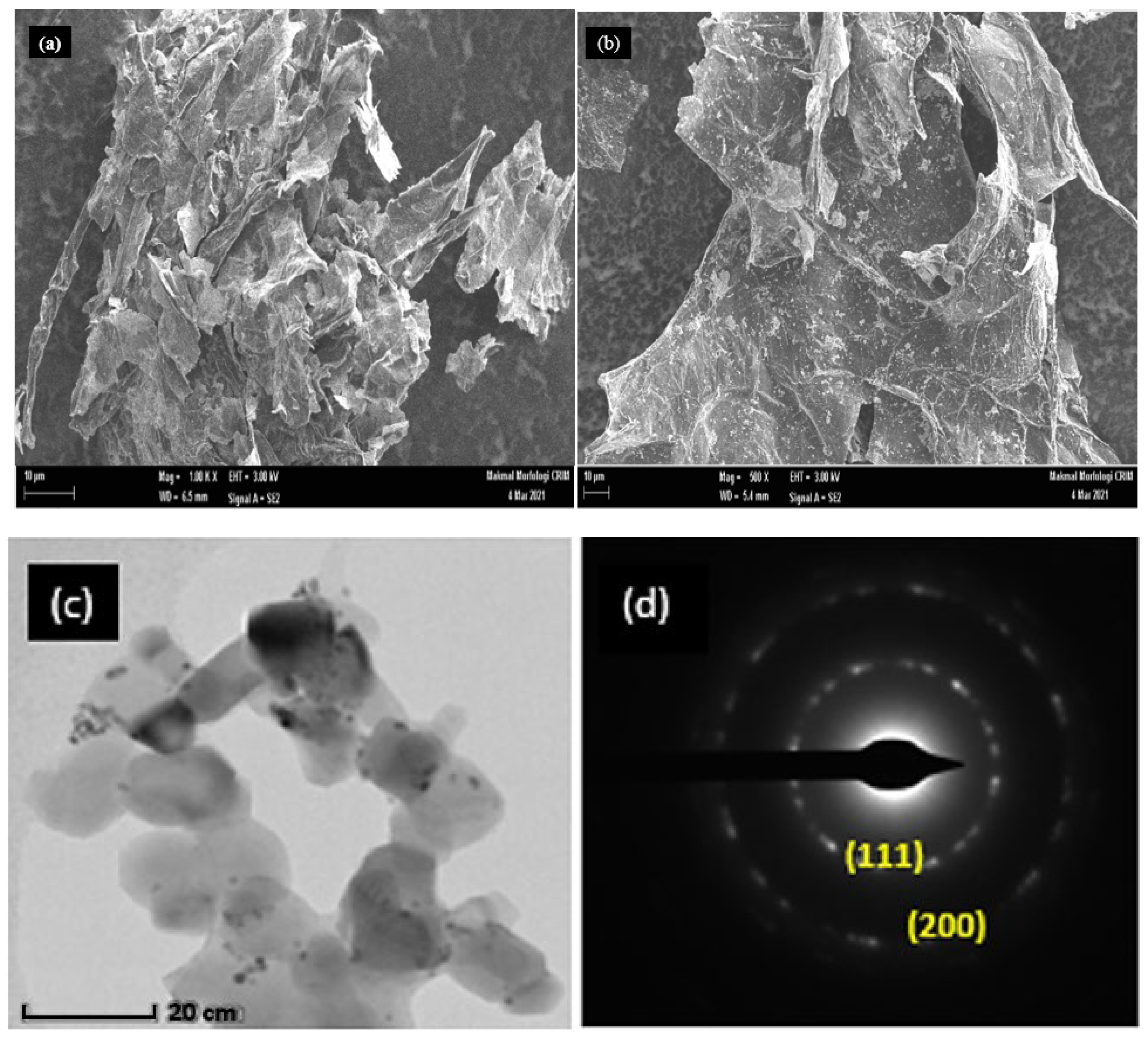
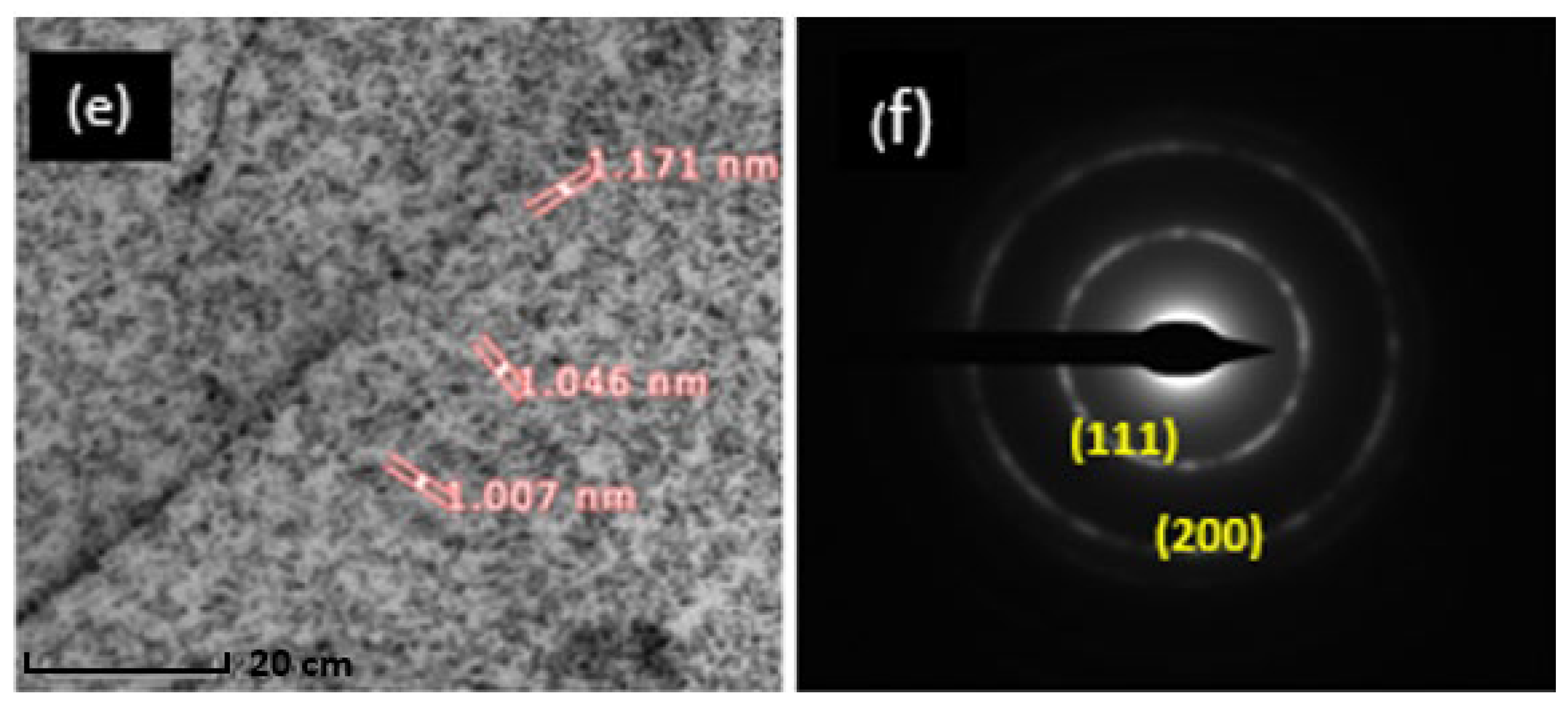
2.1. Characterization of Materials

The XRD analysis of PtRu/GA, GA and GO is shown in Figure 1a. The dominant peak for GA and the XRD pattern with a gap between layers of 3.42 Å was found at 26°. This value is greater than that for the graphite plane, i.e., 3.34 Å, but much smaller than the value of 8.7 Å obtained from the GO peak of 10.6° in 2θ. By removing several oxygen-containing functional groups from GO, a decrease in the distance between layers from GO to GA can be observed. In addition, GA has a broader gap between layers than graphite, indicating residual functional groups on its surface.
GA has a broad peak, and the baseline is not obstructed. This suggests that GA contains a significant amount of amorphous structure [27]. The PtRu/GA XRD patterns exhibit Pt diffraction peaks at 39.7° (111), 46.2° (200), and 67. 5° (220). The spectrum for the catalyst shows Ru diffraction peaks at 40.7° (111), 47° (200), and 69° (220). In this case, we assume that the PtRu in the crystal structure has a face-centred cubic (fcc) structure. GA does not appear to result in any noticeable changes in the crystallization of PtRu nanoparticles [28]. Furthermore, this difference suggests that graphene nanosheets are closely packed, whereas PtRu/GA without stacked graphene nanosheets preserves its three-dimensional structure.
Based on the XRD pattern, it can be concluded that the PtRu/GA nanocomposite catalyst prepared in this study has an FCC structure, which is consistent with the SAED pattern shown in Figure 2f. This indicates that the Pt and Ru precursors were effectively loaded onto the GA without impurities. The diffraction peaks from the PtRu/GA composite are located between the positions of pure FCC-structured monometallic Pt (JCPDS-04-0802) and Ru (JCPDS-46-1043), suggesting the formation of Pt-Ru alloy nanoparticles [29]. The (111) plane dominates the orientation, as evidenced by the most intense peak. Moreover, the width of the diffraction peaks indicates the average size of the nanoparticles, with broader peaks indicating smaller particles. The intensity of the (111) orientation suggests that it was the dominant orientation during the growth process, likely due to a high concentration of atoms and the strong affinity of Pt atoms for that plane. This orientation is highly reactive and has the same d-spacing. The strong and narrow peak indicates that the particles have a high level of crystallinity.
Additionally, no impurity peaks were detected, confirming the formation of pure crystalline platinum. Figure 1b displays the EDX spectrum of the PtRu/GA nanocomposite catalyst, indicating the presence of Pt, Ru, C, and O elements. The appearance of characteristic peaks for these elements indicates the successful formation and deposition of Pt-Ru alloy nanoparticles onto GA. The C peak corresponds to GA, while the O peak results from the remaining oxygen-containing functional groups in GA due to incomplete chemical reduction from GO to GA. The EDX spectrum of the Pt-Ru alloy Figure 1c reveals overlapping peaks for Pt and Ru, providing strong evidence of the formation of a Pt-Ru alloy structure. The respective atomic ratios of the elements are known or taken into consideration. Therefore, EDX can be used to determine the composition of a Pt-Ru alloy. This can be accomplished by contrasting the alloy’s X-ray emissions with those of a fictitious alloy with a known or assumed composition. However, these estimates might not be extremely precise or accurate because of EDX’s limitations. Therefore, the use of a more quantitative approach, such as ICP-AES, is advised for atomic ratios that are more exact. Additionally, the atomic ratio of Pt to Ru, assumptions by their EDX line scanning profiles, is approximately 51:49, which closely matches the theoretical composition of a 1:1 ratio. This further confirms the successful formation of the Pt-Ru alloy.
Interestingly, analysis of the Raman spectrum enables the identification of the carbon species in the sample, which can be used to investigate further the electrocatalysts produced. The structural change in GO, which occurs during the hydrothermal process, was studied by Raman spectroscopy. Figure 1d illustrates the bands observed at approximately 1344–1351 cm−1 and 1577–1598 cm−1, corresponding to the D and G bands for GO, GA, and PtRu/GA to the existence of poly-crystalline graphite [30]. The G band generally corresponds to the vibrational modes of the sp2 hybridized carbon atoms in the graphite layer. At the same time, the large D-band peaks indicate the low crystallinity of the GA support. Analysis of the Raman spectrum also shows that the higher the value of ID/IG, the more defects are present in the graphite. The ID/IG intensity ratio for the bands was calculated from the Raman spectra: PtRu/GA (1.02), GA (1.10), and GO (0.94). The degree of graphitization can be calculated from the relative intensity ratio of the D and G bands (ID/IG), which varies depending on the type of graphite material. The higher the (ID/IG) value, the more flaws there are in graphite. However, the ID/IG value for the PtRu/GA electrocatalyst was only slightly increased in this instance. Graphite in the sample has very little flaw or disorder, which is meant [31]. The PtRu metal addition, which may have slightly altered the GA structure, can also be linked to this issue. The intensity ratio for the ID/IG bands for GO (0.94) is increased compared to GA (1.10), which is similar to a previous description [32]. This increase reveals that the average sp2 domain size is decreased during the synthesis process, which is most likely due to the production of a significant number of new smaller graphitic domains [33]. Furthermore, even after the catalyst is disseminated on the GA support, the resultant (ID/IG) ratio is similar to that obtained for the electrocatalyst samples in this work. Consequently, the carbon layers in these electrocatalyst samples in the disordered and structured portions of the GA structure are not significantly different.
Figure 2a,b, FESEM shows that the electrocatalyst has a well-developed 3D link porosity network, consistent with hydrothermally produced 3D graphene [34]. In addition, the pore structure of the generated samples will facilitate the mass transit of reactants and products [35]. The graphene sheets are stacked in Figure 2a, and this discovery aligns with the findings shown in Figure 1a. As shown in Figure 2b, a porous 3D structure is maintained on the PtRu/GA electrocatalyst, which allows reactant transport. At the same time, a negative influence on the surface of the platinum particles is limited by the structure of the graphene sheets. Platinum particles with a size of 1–3 nm are uniformly distributed on a graphene nanosheet, as shown in Figure 2c,e. Based on Figure 2f, the particles have the same size as the PtRu/GA particles, which indicates that GA and GO have similarities in terms of the absorption and scattering ability of the particles. The selected area electron diffraction (SAED) pattern in Figure 2d,f clearly shows the face-centred cubic (FCC) or crystalline structure of the as-prepared Pt-Ru alloy nanoparticles. The (111), (200) and (220) planes of the crystalline FCC structure are attributed to the three concentric rings and dots formed in the SAED evaluation from the inside to the outside. The fabrication result for PtRu/GA provides a concentric ring light spot, indicating that the resulting sample has a highly crystalline structure. These results are consistent with the XRD data in Figure 1a, which show that PtRu crystals have crystal defects and multiple domains.

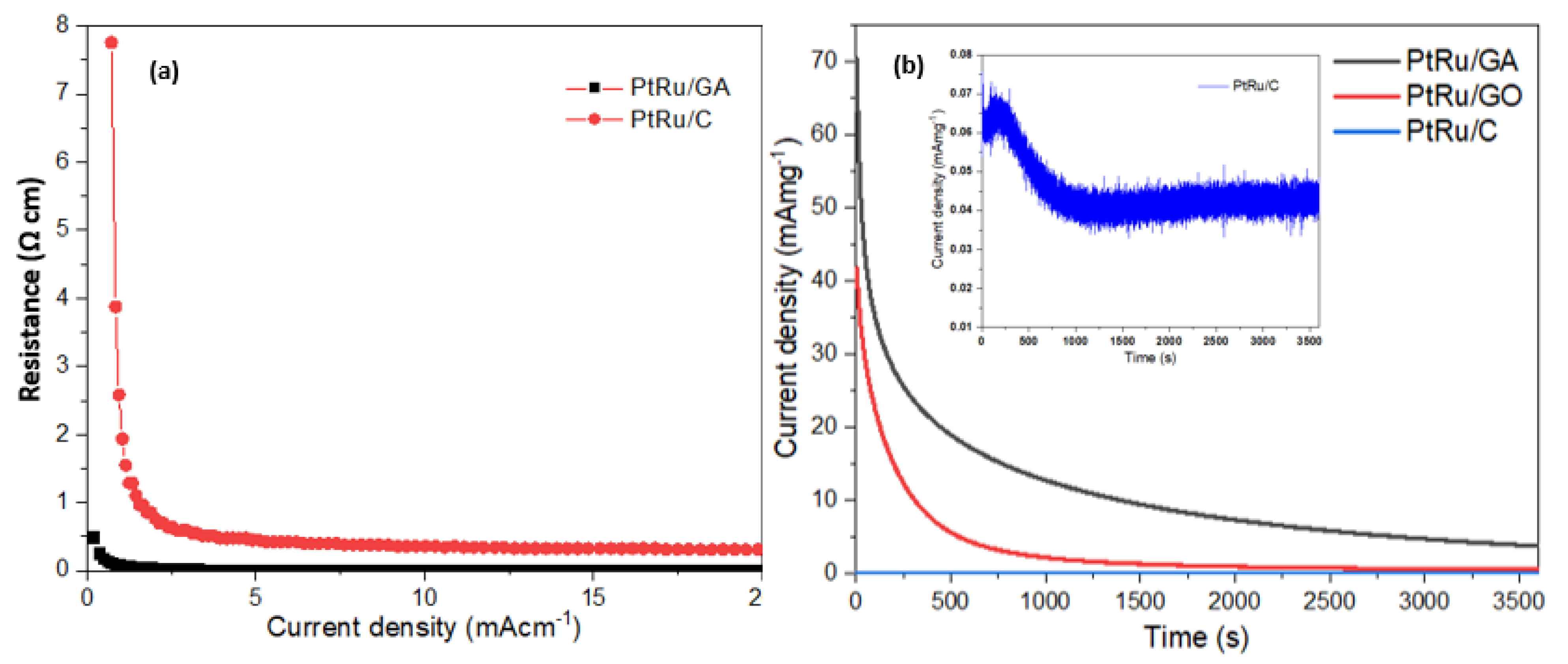
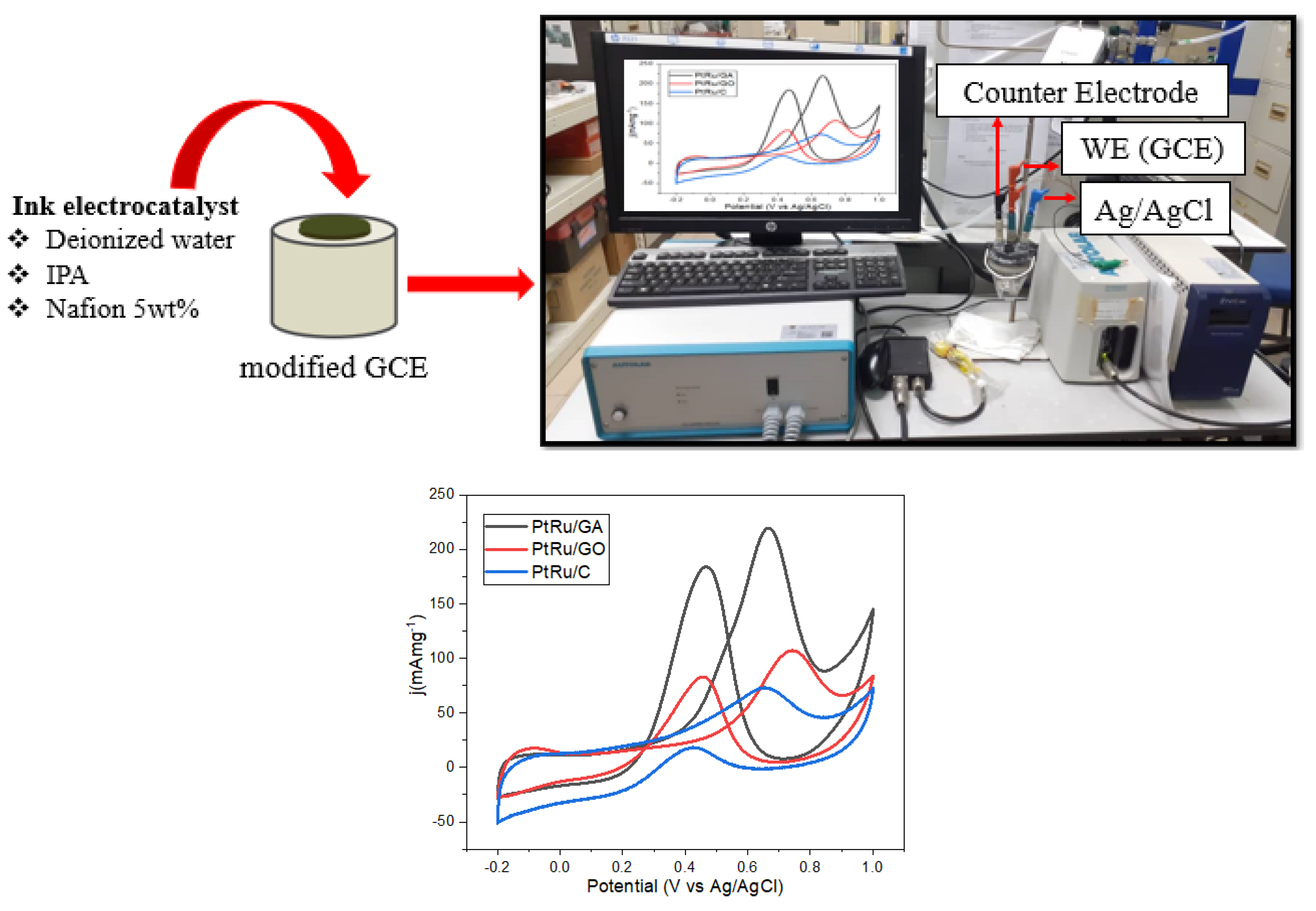
2.2. Electrochemical Evaluation

The potential and effectiveness of all catalysts were electrochemically characterized and determined to be anodic catalysts in DMFCs. This segment includes two main measurements: cyclic voltammetry (CV) and chronoamperometry (CA), which analyse electrocatalytic performance. This was carried out to determine how stable and durable the samples are in the long term. Figure 3a depicts the CV profiles measured for all catalysts in a 0.5 M H2SO4 solution with potentials ranging from −0.2 V to 1.0 V. The hydrogen adsorption/desorption area is also reported on the scale of −0.2 V to 0.1 V, which was used to determine the electrochemical active surface area (ECSA). The ECSA is a method for calculating the surface area of PtRu nanoparticles in an electrocatalyst [36]. Charge transfer reactions at the activation sites are adsorption limited; therefore, this approach requires a cycle of electrode current in the voltage range. ECSA employs the full charge necessary for monolayer adsorption and desorption as reactive surface sites [37].
In general, the larger ECSA of a catalyst usually possesses higher electro-catalytic activity. The methanol oxidation reaction (MOR) performance of anode catalyst is a significant factor influencing DMFC’s efficiency. The common methanol electrooxidation reaction steps with Pt-based alloy catalyst are given in Equations (1)–(3) as shown below [38]:
PtRu + CH3OH → PtRu-COad + 4H+ + 4e
PtRu + H2O → PtRu-OHad + H+ + e
PtRu-COad + Pt-Ru-OHad → CO2 + 2PtRu + H+ + e
From Equation (1), the intermediate species of carbon monoxide (CO) is produced during MOR and then further adsorbed onto the surface of the Pt-Ru catalyst (PtRu-COad). The produced COad block the surface of the Pt-Ru catalyst, thereby suppressing the continuous MOR. The PtRu-COad can be oxidized by the hydroxyl group (OH) to form carbon dioxide (CO2). GA acts as Pt-PRu catalyst support which can prevent the agglomeration of the nanoparticles during MOR and enhance the durability of the catalyst. The calculated ECSA for the CV observation is shown in Table 1. The ECSAs for PtRu/GA, PtRu/GO, and PtRu/C were computed to be approximately 38.49 m2g−1, 20.44 m2g−1, and 19.65 m2g−1, respectively. PtRu/GA has an ECSA of approximately two times that of PtRu/C. This finding demonstrates that preserving a 3D structure while raising the ECSA for PtRu nanoparticles and improving catalyst utilization is possible with GA.
CV was used to examine the catalytic activity of the synthesized electrocatalyst and other electrocatalysts, as shown in Figure 3b. The CV curves obtained for the PtRu/GA, PtRu/GO, and PtRu/C electrocatalysts were evaluated in 0.5 M H2SO4 with 1 M CH3OH with saturated N2 gas at room temperature. The potential range for the several curves is −0.2 to 1.0 V versus Ag/AgCl. The data show well-known methanol oxidation characteristics, with identifiable anode peaks at 0.60 V for all catalysts. For the oxidation of methanol at PtRu, a kinetically controlled reaction occurs because of this process, a huge anodic peak amplitude is presented, and a larger anodic current density will result from a large electrocatalytic activity. PtRu/GA has a peak current density of 219.78 mAmg−1 PtRu, which is 2.1 times that of PtRu/GO (107.06 mAmg−1 PtRu) and three times that of commercial PtRu/C (73.11 mAmg−1 PtRu). This indicates that PtRu/GA has significantly higher electrochemical activity than PtRu/GO and Pt/C, owing to the increased ECSA of PtRu nanoparticles on PtRu/GA.
Table 1 illustrates the CV curves for CO tolerance, onset oxidation potential, and forward oxidation potential for all electrocatalysts generated in the MOR. Throughout the forward scan, the forward oxidation peak (If) reflects the oxidation of specific adsorbed species of methanol, while the elimination of carbonaceous species owing to incomplete oxidation is shown by the reverse oxidation peak (Ib) [39]. The If and Ib ratios also indicated in Table 1, can be utilized to determine the ability of electrocatalysts to tolerate CO intermediate molecules during methanol oxidation. Based on the minimal number of carbonaceous species remaining, a high If/Ib ratio in the forward scan suggests an effective electrocatalyst in methanol oxidation. According to the CV data given in Table 1, the If/Ib value for the PtRu/C electrocatalyst is the largest (3.94) when compared to the PtRu/GO (1.29) and PtRu/GA (1.19) electrocatalysts, indicating that the PtRu/C electrocatalyst has greater CO tolerance. This finding demonstrates that using a nanostructure structure and a metal oxide combination in an electrocatalyst can help to solve the critical challenge for DMFC technology and has strong potential to replace the commercial supports that are now used in this technology.
Electrocatalysts on manufactured PtRu/GA were compared to various PtRu supports for electrocatalysts in DMFCs, such as nanostructured catalysts and metal oxide combinations, as shown in Table 2. The results demonstrate that PtRu/GA has the highest peak current density among all electrocatalysts.
To highlight the distinction, this study used mass activities (mAmg−1) and specific activity (mAcm2), as illustrated in Figure 3 to give a standard evaluation by normalizing the current for the PtRu mass loading and the ECSA, respectively as to make a comparison for all. Notably, the specific activities of the catalysts were evaluated for relevance to the ECSA in the current context. The PtRu mass utilization efficiency can be determined using a specific activity (mA/cm2PtRu) for which PtRu/GA has an abnormally high mass activity of 219.78 mA/mg tiny amount of specific activity (mA/cm2PtRu). For the histogram shown in Figure 3d, PtRu has a utilization of approximately 0.287 mA/cm2 compared to other Pt electrocatalysts with high utilization of Pt mass, in line with the histogram for a particular activity. This indicates that PtRu/GA is successful in achieving excellent catalytic activity. PtRu/GA has a higher electrochemical activity because of the well-distributed and uniform size of PtRu particles and a higher ECSA value, which results in many electrochemically active sites.
To provide a deeper understanding of how methanol oxidation works at a molecular level, it is important to consider the variations in structure and mechanical stability between different samples. Figure 4a offers a clear visualization of how the electrical properties of these samples vary, as it depicts the relationship between resistivity and material density. Notably, there are significant disparities between the performance of PtRu/GA and commercial samples. PtRu/GA demonstrates low resistivity and a strong potential for use in anodic catalyst reactions due to its tendency towards the high current. PtRu/GA, PtRu/GO, and PtRu/C catalysts were chronoamperometrically tested for 3600 s in 0.5 M H2SO4 containing 1.0 M CH3OH at a fixed potential of 0.60 V to determine their long-term electrocatalytic activity and stability against methanol oxidation. Two electrocatalysts were compared to commercial PtRu/C in this study. These tests are crucial for assessing activity and ensuring electrocatalytic activity against methanol oxidation reactions over a time-consuming need. Instead, Figure 4b shows their corresponding curves, while Table 3 shows the long-term stability analysis results. Initially, all the catalysts were found to have a high current value, which may be attributable to numerous active sites on their surfaces.
Continuous oxidation of methanol fuel on the catalyst surface at a fixed potential (0.60 V) occurs during the MOR. As a result, various intermediate-adsorbed CO species begin to form on the catalyst surface. As demonstrated, the initial current for the PtRu/GA nanocomposite catalyst is substantially higher than that for the PtRu/GO and PtRu/C catalysts, implying higher double-layer charging [45]. Within the first 1000 s of the experiment, the PtRu/GA nanocomposite catalyst demonstrates a faster current decay than the PtRu/C catalyst, with an approximately 80% loss compared to 40% [46]. Even though a decline in current was observed, the PtRu/GA nanocomposite catalyst showed a much higher current than the PtRu/GO and PtRu/C nanocomposite catalysts for the entire period. PtRu/GA nanocomposite catalysts have a final current density of 3.79 mA/cm2, which is higher than that of the PtRu/GO (0.57 mA/cm2) and PtRu/C (0.04 mA/cm2) catalysts (see Figure 4 for a better version).
Furthermore, compared to PtRu/GO (98.6%) and PtRu/GA (94.6%), the PtRu/C nanocomposite catalyst shows the lowest calculated decrease in current density (42.9%), demonstrating that the Pt-Ru alloy nanocomposite catalyst is more tolerant of toxins during MOR. The current decays slowly or gradually over time, indicating that the catalyst has good anti-poisoning properties [8]. The PtRu/GA nanocomposite catalyst displays a slower current decline than a conventional catalyst. As a result, the PtRu/GA nanocomposite catalyst outperforms the PtRu/GO and PtRu/C catalysts regarding the electrocatalytic activity and stability of the methanol oxidation process. The outcomes show that oxidation processes are encouraged by acidic conditions because they promote an environment that increases the likelihood that they will take place in the methanol oxidation reaction in an acidic medium. In addition, acidic conditions, which aid in neutralizing these charges and improve their stability, can stabilize the positively charged intermediate species created during oxidation processes. As synthesized, the PtRu/GA nanocomposite catalyst seems promising for DMFC anode catalytic applications.

3. Experimental Section

3.1. Materials

Merck provided a platinum precursor (H2PtCl6) with a Pt concentration of 40%. Graphene oxide was obtained from GO Advanced Solution Sdn. Bhd. Ruthenium precursor (RuCl4), isopropyl alcohol, ethylene glycol (EG), Nafion solution, methanol, and ethanol were obtained from Sigma–Aldrich (St. Louis, MO, USA).

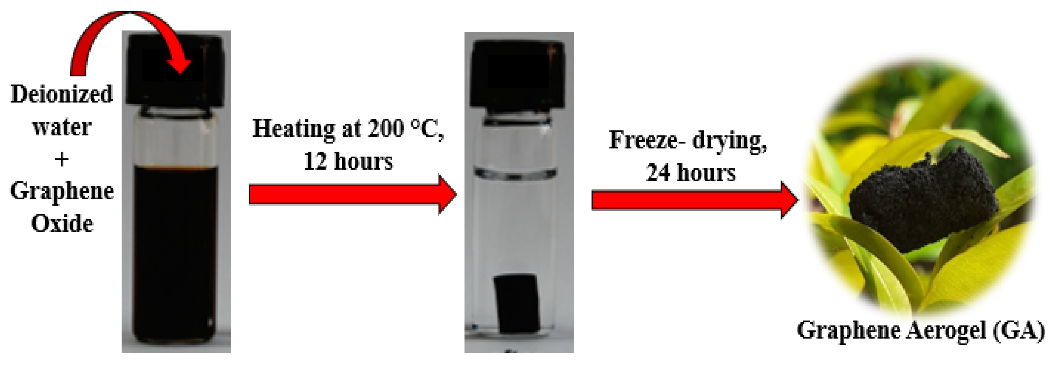
3.2. Formulation of the GA Support

An 80 mg GO was put into 40 mL of distilled water at the start of production to create a composite produced in the lab. This solution was prepared using ultrasonic, sonic mixing to achieve a homogeneous solution before being transported to a Teflon-coated autoclave with a stainless-steel enclosure. The graphene hydrogel was then subjected to hydrothermal treatment for 12 h in an oven at 200 °C. The autoclave was then allowed to cool to room temperature before performing a freeze-drying process for 24 h to generate a graphene aerogel sample. Figure 5 depicts the creation of graphene aerogels using a combination of hydrothermal and freeze-drying techniques.

3.3. Synthesis of the PtRu/GA Electrocatalyst

The study will select the optimal GA support for doping with a Pt-Ru catalyst. The GA support will be loaded with 20 wt% of Pt-Ru in a 1:1 atomic ratio. Initially, the Pt source, chloroplatinic acid, and the Ru source, ruthenium chloride, will be mixed with Ethylene Glycol (EG) solutions in a 70:30 ratio of EG to DI (v/v) and sonicated for 15 min. Subsequently, the precursor solutions will be added to the synthesized GA powder and stirred for 30 min until well mixed. Next, the pH of the solution was changed to a value of 10 using a 1 M NaOH solution. In addition, the mixture was heated in a microwave for 1 min and then turned off twice for 1 min to complete the reduction process. Finally, the sample was dried in an oven at 120 °C for 3 h, filtered, and washed numerous times with DI water and ethanol.

3.4. Preparation of the Working Electrode

An Autolab electrochemical workstation was used to examine the electrochemical measurements, as shown in Figure 6. The catalyst slurry was produced by ultrasonically dispersing 2.5 mg catalyst in a solution of 150 µL deionized water, 150 µL isopropyl alcohol, and 50 µL Nafion (5 wt%) solution for 20 min. In this experiment, a working electrode known as a glassy carbon electrode (GCE) with a diameter of 3 mm was used (this electrode was glossy with an alumina suspension), where 2.5 µL of catalyst ink was drop cast onto the top GCE surface and dried at room temperature overnight before testing the performance the next day.

3.5. Structural Characterization

Sample-ray diffraction (XRD) is a powerful physical characterization technique that may be utilized to demonstrate manufactured materials’ crystallinity and determine their physical characteristics. The size of the catalyst particles and the phase of the prepared catalysts were determined through X-ray diffraction (XRD) analysis using a D-8 Advance diffractometer (Bruker) with Cu Ka (λ = 0.154056 nm) radiation source. This analysis was carried out at room temperature, and the voltage and current were set at 40 kV and 30 mA, respectively. The 2q range values between 5 and 100 were used to obtain the X-ray diffractogram. Scherer’s equation was employed to calculate the crystallite size of the catalyst from the XRD data.
d = K λ β cos Ѳ
The average diameter of the catalyst can be calculated in nanometers using Scherer’s constant (K = 0.89), the wavelength of the radiation (l = 0.154056 nm), the full width at half maximum of the diffraction peak (111) in radians (b), and the Bragg diffraction angle (q).
Concurrently, the degree of graphitization can be determined via Raman spectrum analysis. The surface morphology and forms of the samples were studied using a field emission scanning electron microscope (FESEM). In contrast, transmission electron microscopy (TEM) was performed using a JEM-1010 JEOL apparatus with a voltage of 100 kV.

3.6. Electrochemical Characterization

For this study, the catalyst’s electrochemical surface area (ECSA) was evaluated in a 0.5 M H2SO4 solution, and the electrocatalytic activity for methanol oxidation was investigated in a 0.5 M H2SO4 + 1 M CH3OH solution. Next, an electrode electrochemical analyzer was utilized to record all data using cyclic voltammetry (CV) at a scan rate of 50 mVs−1. Table 1 contains the ECSA results, and CV measurements were used to evaluate ECSA using the equation below.
ECSA   ( m 2 g Pt 1 ) = Q Γ . W Pt
Based on the equation, Q is the charge density or area under the graph ((C) of experimental CV), Γ (2.1 CmPt−2) is the constant for the charge required to reduce the proton monolayer on the Pt, and WPt is the Pt loading (gPt) on the electrode. The electrocatalytic activity of the PtRu/GA electrocatalysts MOR using 0.5 M H2SO4 + 1 M CH3OH solution was tested using a cyclic voltammogram (Figure 3). The anodic peak current density for the sweep is associated with the oxidation of freshy chemisorbed species originating from methanol adsorption [47]. Chronoamperometry measurements were performed for 3600 s a with a step potential of 0.6 V [48]. Each experiment was purged for 15 min with high-quality nitrogen gas to achieve oxygen-free content. Gas chromatography-mass spectrometry (GCMS) is a powerful analytical technique used to identify and quantify the chemical compounds present in a gas sample. In addition, each electrochemical experiment was conducted using a fresh electrolyte solution to assure repeatability. In addition to testing the strength of the electrocatalyst, the retention value of the electrocatalyst is checked by CA, which focuses on the level of resistance or force of the electrocatalyst object during operation for a certain period according to the following equation [40];
Retention   value =   Initial   current   density     Final   current   density Initial   current   density × 100 %
To further clarify the catalytic performance of the electrocatalysts toward MOR, the poisoning tolerance was evaluated. The forward anodic peak current (IF) to the backward anodic peak current (IB) ratio, IF/IB, can be employed to evaluate the tolerance to accumulated CO and other adsorbed species [40]. A higher IF/IB ratio generally implies a more effective removal of CO and other adsorbed intermediates on the electrocatalyst surface during the anodic scan [42].

4. Conclusions

This work describes a novel graphene aerogel support for bimetallic PtRu that was successfully fabricated using an environmentally friendly hydrothermal reaction with a working temperature range of 200 °C and a freeze-drying approach. A PtRu/GA electrocatalyst was fabricated from the best GA utilizing a simple microwave-aided alcohol-reduction approach, and the results obtained from prior investigations of bimetallic catalysts were compared. This work describes the synthesis, characterization, and chemical activities of bimetallic PtRu with a graphene aerogel support and its catalytic abilities in a direct methanol fuel cell. XRD, Raman spectroscopy, FESEM, and TEM studies were used to determine the structure, composition, and morphology of the as-synthesized PtRu/GA. PtRu/GA also has an excellent 3D porous structure that prevents the active surface area loss found for stacked graphene sheets, according to FESEM images. In addition, all electrocatalysts were compared to PtRu/C. The as-prepared PtRu/GA nanocomposite catalyst showed a significantly greater ECSA, superior electrocatalytic activity, lower onset potential, more significant peak current, and improved stability against the MOR. The high surface area and synergistic impact of the generated PtRu alloy nanoparticles with high dispersion on the surface area of the GA support can contribute to these findings. As a result, this study offers a new avenue for catalyst development, raising the prospect of utilizing the as-developed PtRu/GA nanocomposites as a viable DMFC catalyst. Alternatively, PtRu/GA synthesis can be easily expanded to prepare various GA-integrated nanomaterials with diverse uses in photocatalysis, sensors, batteries, and super-capacitor applications.

Author Contributions

Conceptualization, S.H.O., S.K.K. and S.B.; software, N.A.K.; validation, N.A.K. and S.B.; formal analysis, S.B.; investigation, S.K.K.; writing—original draft preparation, Siti Hasanah Osman.; writing—review and editing, S.H.O.; visualization, S.H.O.; supervision, S.K.K.; project administration, S.K.K.; funding acquisition, S.K.K. All authors have read and agreed to the published version of the manuscript.

Funding

The study received financial support from the Universiti Kebangsaan Malaysia: DIP-2021-028.

Data Availability Statement

Not applicable.

Acknowledgments

The authors gratefully acknowledge the financial support given for this work by Universiti Kebangsaan Malaysia under DIP-2021-028.

Conflicts of Interest

We confirm that the work described has not been published before, it is not under consideration for publication anywhere else, and publication has been approved by all co-authors and the responsible authorities at the institute(s) where the work was carried out. The authors declare no conflict of interest.

References

  1. Osman, S.H.; Kamarudin, S.K.; Karim, N.A.; Basri, S. Application of graphene in low-temperature fuel cell technology: An overview. Int. J. Energy Res. 2021, 45, 1–19. [Google Scholar] [CrossRef]
  2. Ramli, Z.A.C.; Kamarudin, S.K. Platinum-Based Catalysts on Various Carbon Supports and Conducting Polymers for Direct Methanol Fuel Cell Applications: A Review. Nanoscale Res. Lett. 2018, 13, 410. [Google Scholar] [CrossRef]
  3. Hong, W.; Wang, J.; Wang, E. Facile synthesis of PtCu nanowires with enhanced electrocatalytic activity. Nano Res. 2015, 8, 2308–2316. [Google Scholar] [CrossRef]
  4. Bandapati, M.; Goel, S.; Krishnamurthy, B. Platinum utilization in proton exchange membrane fuel cell and direct methanol fuel cell. J. Electrochem. Sci. Eng. 2019, 9, 281–310. [Google Scholar] [CrossRef]
  5. Rambabu, G.; Bhat, S.D. Simultaneous tuning of methanol crossover and ionic conductivity of sPEEK membrane electrolyte by incorporation of PSSA functionalized MWCNTs: A comparative study in DMFCs. Chem. Eng. J. 2014, 243, 517–525. [Google Scholar] [CrossRef]
  6. Rambabu, G.; Sasikala, S.; Bhat, S.D. Nanocomposite membranes of sulfonated poly(phthalalizinone ether ketone)-sulfonated graphite nanofibers as electrolytes for direct methanol fuel cells. RSC Adv. 2016, 6, 107507–107518. [Google Scholar] [CrossRef]
  7. Lori, O.; Elbaz, L. Recent Advances in Synthesis and Utilization of Ultra-low Loading of Precious Metal-based Catalysts for Fuel Cells. ChemCatChem 2020, 12, 3434–3446. [Google Scholar] [CrossRef]
  8. Hanifah, M.F.R.; Jaafar, J.; Othman, M.; Ismail, A.; Rahman, M.; Yusof, N.; Aziz, F.; Rahman, N.A. One-pot synthesis of efficient reduced graphene oxide supported binary Pt-Pd alloy nanoparticles as superior electro-catalyst and its electro-catalytic performance toward methanol electro-oxidation reaction in direct methanol fuel cell. J. Alloy. Compd. 2019, 793, 232–246. [Google Scholar] [CrossRef]
  9. Mahmood, K.; Mansoor, M.A.; Iqbal, M.; Kalam, A.; Iqbal, J.; Jilani, A.; Wageh, S. An Electrochemical Investigation of Methanol Oxidation on Thin Films of Nickel Oxide and Its Composites with Zirconium and Yttrium Oxides. Crystals 2022, 12, 534. [Google Scholar] [CrossRef]
  10. Liaqat, R.; Mansoor, M.A.; Iqbal, J.; Jilani, A.; Shakir, S.; Kalam, A.; Wageh, S. Fabrication of metal (Cu and Cr) incorporated nickel oxide films for electrochemical oxidation of methanol. Crystals 2021, 11, 1398. [Google Scholar] [CrossRef]
  11. Tang, S.; Sun, G.; Qi, J.; Sun, S.; Guo, J.; Xin, Q.; Haarberg, G.M. Review of New Carbon Materials as Catalyst Supports in Direct Alcohol Fuel Cells. Chin. J. Catal. 2010, 31, 12–17. [Google Scholar] [CrossRef]
  12. Hassani, S.S.; Samiee, L. Carbon Nanostructured Catalysts as High Efficient Materials for Low Temperature Fuel Cells. Handb. Ecomater. 2018, 713, 1–28. [Google Scholar] [CrossRef]
  13. Phong, N.T.P.; Nguyen, C.M.T.; Minh, N.H.; Ngo, T.L. Synthesis of Platin/Carbon XC72R Nanocomposite Using as Electrocatalyst for Direct Methanol Fuel Cells. Mater. Sci. 2012, 6, 925–929. [Google Scholar]
  14. Geim, A.K.; Novoselov, K.S. The rise of graphene. Nat. Mater. 2007, 6, 183–191. [Google Scholar] [CrossRef]
  15. Novoselov, K.S.; Geim, A.K.; Morozov, S.V.; Jiang, D.; Katsnelson, M.I.; Grigorieva, I.V.; Dubonos, S.V.; Firsov, A.A. Two-dimensional gas of massless Dirac fermions in graphene. Nature 2005, 438, 197–200. [Google Scholar] [CrossRef]
  16. Smith, A.T.; LaChance, A.M.; Zeng, S.; Liu, B.; Sun, L. Synthesis, properties, and applications of graphene oxide/reduced graphene oxide and their nanocomposites. Nano Mater. Sci. 2019, 1, 31–47. [Google Scholar] [CrossRef]
  17. Papageorgiou, D.G.; Kinloch, I.A.; Young, R.J. Mechanical properties of graphene and graphene-based nanocomposites. Prog. Mater. Sci. 2017, 90, 75–127. [Google Scholar] [CrossRef]
  18. Wang, Y.; Wu, Y.; Huang, Y.; Zhang, F.; Yang, X.; Ma, Y.; Chen, Y. Preventing graphene sheets from restacking for high-capacitance performance. J. Phys. Chem. C 2011, 115, 23192–23197. [Google Scholar] [CrossRef]
  19. Tiwari, S.K.; Sahoo, S.; Wang, N.; Huczko, A. Graphene research and their outputs: Status and prospect. J. Sci. Adv. Mater. Devices 2020, 5, 10–29. [Google Scholar] [CrossRef]
  20. Ma, Y.; Chen, Y. Three-dimensional graphene networks: Synthesis, properties and applications. Natl. Sci. Rev. 2015, 2, 40–53. [Google Scholar] [CrossRef]
  21. Yan, Y.; Nashath, F.Z.; Chen, S.; Manickam, S.; Lim, S.S.; Zhao, H.; Lester, E.; Wu, T.; Pang, C.H. Synthesis of graphene: Potential carbon precursors and approaches. Nanotechnol. Rev. 2020, 9, 1284–1314. [Google Scholar] [CrossRef]
  22. Wang, Y.-S.; Yang, S.-Y.; Li, S.-M.; Tien, H.-W.; Hsiao, S.-T.; Liao, W.-H.; Liu, C.-H.; Chang, K.-H.; Ma, C.-C.M.; Hu, C.-C. Three-dimensionally porous graphene–carbon nanotube composite-supported PtRu catalysts with an ultrahigh electrocatalytic activity for methanol oxidation. Electrochim. Acta 2013, 87, 261–269. [Google Scholar] [CrossRef]
  23. Yaqoob, L.; Noor, T.; Iqbal, N. Recent progress in development of efficient electrocatalyst for methanol oxidation reaction in direct methanol fuel cell. Int. J. Energy Res. 2020, 45, 6550–6583. [Google Scholar] [CrossRef]
  24. Xiong, C.; Li, B.; Lin, X.; Liu, H.; Xu, Y.; Mao, J.; Duan, C.; Li, T.; Ni, Y. The recent progress on three-dimensional porous graphene-based hybrid structure for supercapacitor. Compos. Part B Eng. 2019, 165, 10–46. [Google Scholar] [CrossRef]
  25. Mo, R.; Li, F.; Tan, X.; Xu, P.; Tao, R.; Shen, G.; Lu, X.; Liu, F.; Shen, L.; Xu, B.; et al. High-quality mesoporous graphene particles as high-energy and fast-charging anodes for lithium-ion batteries. Nat. Commun. 2019, 10, 1474. [Google Scholar] [CrossRef]
  26. Aldroubi, S.; Brun, N.; Bou Malham, I.; Mehdi, A. When graphene meets ionic liquids: A good match for the design of functional materials. Nanoscale 2021, 13, 2750–2779. [Google Scholar] [CrossRef] [PubMed]
  27. Thiruppathi, A.R.; Sidhureddy, B.; Boateng, E.; Soldatov, D.V.; Chen, A. Synthesis and electrochemical study of three-dimensional graphene-based nanomaterials for energy applications. Nanomaterials 2020, 10, 1295. [Google Scholar] [CrossRef]
  28. Chen, Z.; He, Y.-C.; Chen, J.-H.; Fu, X.-Z.; Sun, R.; Chen, Y.-X.; Wong, C.-P. PdCu Alloy Flower-like Nanocages with High Electrocatalytic Performance for Methanol Oxidation. J. Phys. Chem. C 2018, 122, 8976–8983. [Google Scholar] [CrossRef]
  29. Baronia, R.; Goel, J.; Kaswan, J.; Shukla, A.; Singhal, S.K.; Singh, S.P. PtCo/rGO nano-anode catalyst: Enhanced power density with reduced methanol crossover in direct methanol fuel cell. Mater. Renew. Sustain. Energy 2018, 7, 27. [Google Scholar] [CrossRef]
  30. Abdullah, M.; Kamarudin, S.K.; Shyuan, L.K. TiO2 Nanotube-Carbon (TNT-C) as Support for Pt-based Catalyst for High Methanol Oxidation Reaction in Direct Methanol Fuel Cell. Nanoscale Res. Lett. 2016, 11, 553. [Google Scholar] [CrossRef]
  31. Chao, L.; Qin, Y.; He, J.; Ding, D.; Chu, F. Robust three dimensional N-doped graphene supported Pd nanocomposite as efficient electrocatalyst for methanol oxidation in alkaline medium. Int. J. Hydrogen Energy 2017, 42, 15107–15114. [Google Scholar] [CrossRef]
  32. Kung, C.-C.; Lin, P.-Y.; Xue, Y.; Akolkar, R.; Dai, L.; Yu, X.; Liu, C.-C. Three dimensional graphene foam supported platinum-ruthenium bimetallic nanocatalysts for direct methanol and direct ethanol fuel cell applications. J. Power Sources 2014, 256, 329–335. [Google Scholar] [CrossRef]
  33. Franceschini, E.A.; Bruno, M.M.; Williams, F.J.; Viva, F.A.; Corti, H.R. High-activity mesoporous Pt/Ru catalysts for methanol oxidation. ACS Appl. Mater. Interfaces 2013, 5, 10437–10444. [Google Scholar] [CrossRef] [PubMed]
  34. Motshekga, S.C.; Pillai, S.K.; Sinha Ray, S.; Jalama, K.; Krause, R.W.M. Recent trends in the microwave-assisted synthesis of metal oxide nanoparticles supported on carbon nanotubes and their applications. J. Nanomater. 2012, 2012, 528–544. [Google Scholar] [CrossRef]
  35. Li, Z.; Jaroniec, M.; Papakonstantinou, P.; Tobin, J.M.; Vohrer, U.; Kumar, S.; Attard, G.; Holmes, J.D. Supercritical fluid growth of porous carbon nanocages. Chem. Mater. 2007, 19, 3349–3354. [Google Scholar] [CrossRef]
  36. Stankovich, S.; Dikin, D.A.; Piner, R.D.; Kohlhaas, K.A.; Kleinhammes, A.; Jia, Y.; Wu, Y.; Nguyen, S.T.; Ruoff, R.S. Synthesis of graphene-based nanosheets via chemical reduction of exfoliated graphite oxide. Carbon 2007, 45, 1558–1565. [Google Scholar] [CrossRef]
  37. Chadha, N.; Sharma, R.; Saini, P. A new insight into the structural modulation of graphene oxide upon chemical reduction probed by Raman spectroscopy and X-ray diffraction. Carbon Lett. 2021, 31, 1125–1131. [Google Scholar] [CrossRef]
  38. Zhang, Y.; Wan, Q.; Yang, N. Recent Advances of Porous Graphene: Synthesis, Functionalization, and Electrochemical Applications. Small 2019, 15, 1903780. [Google Scholar] [CrossRef]
  39. Lin, Y.; Liao, Y.; Chen, Z.; Connell, J.W. Holey graphene: A unique structural derivative of graphene. Mater. Res. Lett. 2017, 5, 209–234. [Google Scholar] [CrossRef]
  40. Nishanth, K.G.; Sridhar, P.; Pitchumani, S.; Shukla, A.K. Enhanced Methanol Electro-Oxidation on Pt-Ru Decorated Self-Assembled TiO 2 -Carbon Hybrid Nanostructure. ECS Tran.s 2011, 41, 1139–1149. [Google Scholar] [CrossRef]
  41. Lin, Y.; Cui, X.; Yen, C.H.; Wai, C.M. PtRu/carbon nanotube nanocomposite synthesized in supercritical fluid: A novel electrocatalyst for direct methanol fuel cells. Langmuir 2005, 21, 11474–11479. [Google Scholar] [CrossRef] [PubMed]
  42. Chen, Y.-W.; Chen, H.-G.; Lo, M.-Y.; Chen, Y.-C.; Lo, M.-Y.; Chen, Y. Modification of Carbon Black with Hydrogen Peroxide for High Performance Anode Catalyst of Direct Methanol Fuel Cells. Materials 2021, 14, 3902. [Google Scholar] [CrossRef] [PubMed]
  43. Basri, S.; Kamarudin, S.K.; Daud, W.R.W.W.; Yaakob, Z.; Kadhum, A.A.H.H. Novel anode catalyst for direct methanol fuel cells. Sci. World J. 2014, 2014, 547604. [Google Scholar] [CrossRef]
  44. Guo, J.W.; Zhao, T.S.; Prabhuram, J.; Chen, R.; Wong, C.W. Preparation and characterization of a PtRu/C nanocatalyst for direct methanol fuel cells. Electrochim. Acta 2005, 51, 754–763. [Google Scholar] [CrossRef]
  45. Kung, C.-C.; Lin, P.-Y.; Buse, F.J.; Xue, Y.; Yu, X.; Dai, L.; Liu, C.-C. Preparation and characterization of three dimensional graphene foam supported platinum-ruthenium bimetallic nanocatalysts for hydrogen peroxide based electrochemical biosensors. Biosens. Bioelectron. 2013, 52, 1–7. [Google Scholar] [CrossRef] [PubMed]
  46. Arukula, R.; Vinothkannan, M.; Kim, A.R.; Yoo, D.J. Cumulative effect of bimetallic alloy, conductive polymer and graphene toward electrooxidation of methanol: An efficient anode catalyst for direct methanol fuel cells. J. Alloy. Compd. 2019, 771, 477–488. [Google Scholar] [CrossRef]
  47. Yamada, H.; Yoshii, K.; Asahi, M.; Chiku, M.; Kitazumi, Y. Cyclic Voltammetry Part 2: Surface Adsorption, Electric Double Layer, and Diffusion Layer. Electrochemistry 2022, 90, 102006. [Google Scholar] [CrossRef]
  48. Ng, J.C.; Tan, C.Y.; Ong, B.H.; Matsuda, A. Effect of Synthesis Methods on Methanol Oxidation Reaction on Reduced Graphene Oxide Supported Palladium Electrocatalysts. Procedia. Eng. 2017, 184, 587–594. [Google Scholar] [CrossRef]
Figure 1. (a) XRD patterns and (b) typical EDX spectrum of PtRu/GA nanocomposite catalyst (c) the EDX spectrum of individual Pt-Ru alloy nanoparticle (d) Raman spectra of GO, GA, and PtRu/GA.
Catalysts 13 00879 g001
Figure 2. FESEM images (a) PtRu/GO, (b) PtRu/GA, TEM image (c) PtRu/GO, (e) PtRu/GA SAED pattern (d) PtRu/GO, (f) PtRu/GA.
Catalysts 13 00879 g002aCatalysts 13 00879 g002b
Figure 3. Represent (a) the H2 absorption and desorption of PtRu catalyst in 0.5 M H2SO4, (b,c) CV curves in 0.5 M H2SO4 and 1 M CH3OH aqueous at 50 mVs−1 and (d) histogram of mass activity and specific activity for electrocatalyst.
Catalysts 13 00879 g003
Figure 4. (a) Resistance curves of commercial PtRu/GA and PtRu/C (b) Chronoamperometric curves in 0.5 M H2SO4 + 1 M CH3OH solution.
Catalysts 13 00879 g004
Figure 5. Graphene aerogel (GA) synthesis.
Catalysts 13 00879 g005
Figure 6. Electrochemical test with Autolab electrochemical workstation.
Catalysts 13 00879 g006
Table 1. Comparison of the current density results with the different electrocatalysts.
EletrocatalystECSA (m2/gPtRu)Peak Potential (V vs. Ag/AgCl)Onset Potential (V vs. Ag/AgCl)Mass Activity (mA/mgPtRu)Specific Activity (mA/cm2PtRu)CO Tolerance If/Ib Ratio
PtRu/GA38.490.670.205219.780.2871.19
PtRu/GO20.440.7390.211107.060.2631.29
PtRu/C19.650.6490.38773.110.1873.94
Table 2. Comparison of the performance results with the previous study.
AuthorsElectrocatalystPeak Potential
(V vs. RHE)
Peak Current Density
(mA/mgPtRu)
This studyPtRu/GA0.8640.287 mA/cm2
219.78 mA/mg
Nishanth et al. [40]PtRu/TiO2-C0.761151.47
Lin et al. [41]PtRu/CNT0.85766.69
Chen et al. [42]PtRuWOx/C0.91356.02
Basri et al. [43]PtRuNiFe/MWCNT0.94131
Guo et al. [44]PtRu0.7(CeO2)0.3/C0.19121.43
Table 3. Summary results of the long-term stability test for nanocomposite catalysts.
ElectrocatalystInitial Current
Density (mAcm−2)
Final Current Density at 3600 s (mAcm−2)Current Density Decline (%)
PtRu/GA70.263.7994.6
PtRu/GO42.210.5798.6
PtRu/C0.070.0442.9
Disclaimer/Publisher’s Note: The statements, opinions and data contained in all publications are solely those of the individual author(s) and contributor(s) and not of MDPI and/or the editor(s). MDPI and/or the editor(s) disclaim responsibility for any injury to people or property resulting from any ideas, methods, instructions or products referred to in the content.

