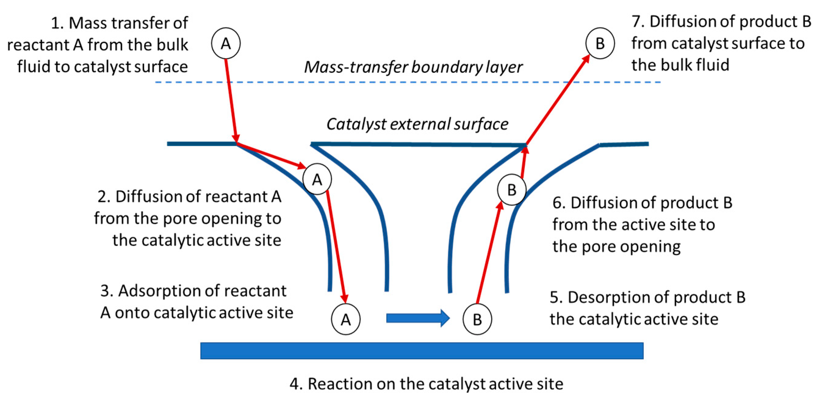
4.2. Diffusion in Solid Heterogeneous Catalysts
When the diffusion steps 1, 2, 6, and 7 in
Figure 5 (adapted from [
21]) are quick compared with the surface reaction-rate steps (3, 4, and 5), the concentrations close to the active sites are indistinguishable from those in the bulk fluid. In this situation, the transport or diffusion steps do not affect the overall rate of the reaction [
21].
Mass transport will affect the reaction rate if the reaction steps are very fast compared to the diffusion steps. In systems where the reaction rate is affected by mass transfer (diffusion) from the bulk fluid to the external catalyst surface through the boundary layer, the change in flow conditions around the catalyst will cause the boundary layer thickness to change, with consequences on the overall reaction rate.
Once inside the catalyst, diffusion within the catalyst pores may limit the rate of reaction, and, as a result, the overall rate will not be affected by the external flow regime but by internal diffusion.
Textural characterization provides valuable information to understand the diffusion mechanism within the catalyst. Some parameters such as specific area, pore volume, particle specific gravity, porosity, and tortuosity are involved in diffusion. IUPAC (International Union of Pure and Applied Chemistry) [
22] establishes a classification for porous materials: pore shape and pore diameter. As for the pore diameter, IUPAC proposes the classification shown in
Table 6.
4.3. The Importance of Diffusivity in FCC Catalysts
Among the challenges for the catalyst, one may highlight the eventual transport limitation of feed to be cracked into products within the catalyst. The diffusion of feed molecules into the catalyst depends on their size [
23]: the larger they are, the more difficult it is for them to diffuse into the catalyst pores. Large feed molecules cannot readily enter the zeolite Y super cage (12.5 Å), the opening of which is only 7.4 Å in diameter [
24]. These large molecules must first be cracked on the matrix surface [
25].
Catalytic hydrocarbon cracking reactions require strong Brønsted acid sites [
26]. Steaming, i.e., treatment with high-temperature water vapor, strongly affects the activity of Y zeolite. A proper steaming of Y zeolite could enhance the cracking activity by over two orders of magnitude. However, excessive steaming leads to a decline in activity from the optimal value.
Zeolite Diffusion
In zeolite-catalyzed processes, limitations imposed by the low, fixed rate of intracrystalline micropore diffusion can remarkably affect catalyst performance [
27]. Introducing meso- or macropores may be beneficial for the catalytic performance, i.e., the overall conversion and the selectivity towards desired products. Additionally, the diffusion path of reactants is reduced, and the accessibility to the active sites is enhanced, which extends the catalyst’s lifetime.
Steaming of the zeolite generates cracks, fissures, mesopores, and other defects. These lead to a substantially larger effective external area for diffusion, which then leads to a considerable enhancement in the observed activity. However, steaming also generates non-framework alumina and silica-alumina debris that may block the micropores or the active sites, attenuating the enhancement effect.
In reactions dominated by the monomolecular mechanism, the turnover frequency and the intrinsic activation energy for cracking are practically unchanged by steaming [
26]. This observation applies to USY of high SAR because the acidic strength increases when the number of nearest neighbor sites (so-called NNN sites) decreases and almost all acid sites are isolated.
However, a much more significant difference in activity can be observed under conditions where bimolecular and oligomeric cracking dominate. Thus, the phenomenon of enhanced activity by steaming can be explained by the possibility that the bimolecular and oligomeric cracking reactions are pore-diffusion limited.
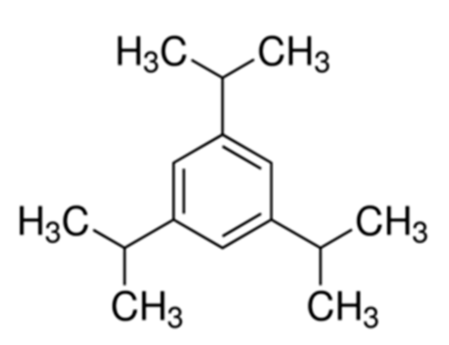
Falabella et al. [
28] have studied the cracking of 1,3,5-triisopropylbenzene (1,3,5-TIPB) over several zeolites with different degrees of dealumination in a differential fixed-bed gas phase plug flow reactor. The 1,3,5-TIPB is a relatively bulky molecule (
Figure 6) with a critical molecular diameter of about 9.5 Å. Due to its large size, it has been used to simulate the diffusional constraints expected in the catalytic cracking of gas oil. The authors pointed out that small zeolite crystals (0.8 μm) have at 370 °C a higher 1,3,5-TIPB conversion than the larger zeolite crystals (1.6 μm). They inferred that this behavior was due to the change in the zeolite external area. The authors concluded that when bulky molecules are used, the effect of the formation of mesopores, hence, the increase in external area (mSA), is capital for diffusion-limited reactions.
Product molecules that have been formed by pre-cracking are small enough to enter the zeolite’s microporous structure, where they are selectively cracked to naphtha. Various residue feeds, however, have different molecular shapes and will behave differently on the catalyst. Molecules in an aromatic residue are bulkier than those in a paraffinic residue [
29]. As a result, it is important to match the pore structure of the catalyst with the molecular size of the residue feed used, which will influence the accessibility to the active sites on the matrix. For a short contact time residue catalyst, the accessibility to the acidic sites and the density of these sites is crucial. Andersson [
29] points out that most of the pre-cracking of the large feed molecules takes place on the mesopores area of the catalyst. Moreover, it is also necessary to have some areas in the macropores for cracking the bulky metal-containing feed molecules.
4.4. Hierarchical Materials
According to the Oxford Learner’s Dictionary of Academic English, a hierarchy (from the Greek ἱεραρχία, hierarkhia, “rule of a high priest”) is “a system, especially in a society or an organization, in which people are organized into different levels of importance from highest to lowest.” Hierarchy is an important and ubiquitous concept in nature, e.g., the leaves and elements of a plant’s root system or the blood vessels in the circulatory system: follow a hierarchical arrangement to optimize structural strength or fluid transport (flow). A wide variety of fields are also hierarchically ordered, such as sociology, business, and military, to name a few [
30].
The concept of hierarchy also applies to porous materials, especially zeolitic catalysts, such as the one used in an FCCU. As stated in the previous section, diffusion along zeolite native microporosity occurs at a fixed rate, and another (hierarchically superior) level of pores—intracrystalline or interparticle—is needed to increase mass transfer [
31].
Hierarchically porous materials can be classified into two types, depending on the interconnectivity pattern among the different pore levels [
32,
33,
34]:
Hierarchy-type I: Interconnected pore system, in which wide pores subdivide into pores of a next lower level (narrower pores).
Hierarchy-type II: Interconnected systems of pores with different widths in which the wide-pore system intersects the narrower pore system, i.e., small pores branch off from a continuous large pore.
Conceptually, one can consider two approaches to obtaining zeolites with accessible sites. The first one is to create paths from the external surface of the zeolite crystal to the bulk (such as the formation of mesopores). The second is to obtain zeolites with a high external area (such as 2-D zeolite slabs and colloidal zeolites). The latter type of zeolites can still pack together in a way that the inter-crystal space is wide and connected to the external surface of the final grain.
The preparation of zeolites containing more than one system of pores has received many reviews in the literature [
33,
34,
35,
36]. This material has been generally referred to as hierarchical zeolite [
30,
37,
38,
39]. The preparation methods can be classified into two types. In the first type, the microporous structures are built simultaneously with the mesoporous support or upon this substrate. This method is also referred to as the bottom-up method. In the second type, a microporous solid is first formed and then mesopores are created by subsequent treatments. This second method is referred to as the top-down method.
The bottom-up synthesis method usually employs one or more Structure Directing Agents (SDA), sometimes called porogen materials or templates. These SDAs are termed “hard templates” when they are just physical spacing agents such as carbon, organic, and inorganic polymeric spheres or networks that are added to a zeolite crystallization reaction mixture but do not participate in the zeolitization reactions. After successful zeolite formation, the SDAs are removed by calcination or alkaline-acid leaching, leaving behind mesopores in their former position. By contrast, there are “soft templates”, chiefly Organic SDAs (OSDAs) derived from those employed to synthesize mesoporous silica-alumina, such as poly-quaternary ammonium surfactants. However, when these OSDAs are used alone, they generally only result in materials with amorphous walls. Hence, they are employed together with [
33,
34,
36]:
Another OSDA that can generate a microporous structure, or
Seeds of a microporous structure, or
Functionalization of the substrate structure, such as the attachment of a group that can help generate a microporous structure.
The main drawback of the bottom-up method is the need to use OSDAs. Not only are OSDAs generally expensive or toxic, but their removal also adds further costs and waste treatment steps to the preparation process. Moreover, removal steps such as calcination or acid-base leaching may damage the structure prepared or alter the active sites of the catalytic reaction. More recently, some successful attempts have been reported in the literature making use of the synthesis conditions that promote the intergrowth of two separate yet related zeolite structures (such as FAU and EMT). Consequently, mesoporous spacing is created between crystallites without the use of a template. However, the generalization of this strategy to prepare various structures cannot be assured [
40].
Top-down methods are post-treatment methods [
33,
36]. Synthesized zeolites go through individual or combined acid, base, and heat treatments to generate a system of secondary pores. The acid treatment, often combined with heat treatment, has been known and employed by the industry for a long time [
35,
41,
42]. Works devoted to the preparation and characterization of zeolites, especially of FAU structure, subjected to these treatments have been widely reviewed. Noteworthy is that as silica is the major component of a zeolite, typical acid treatments will remove the Al in the zeolite framework and will not result in large amounts of mesopores. Furthermore, as Al sites are generally the active sites of a catalytic reaction, the activity of the derived zeolite decreases. Hence, recent works tend to focus on the alkaline treatment of zeolites.
The action of dilute caustic solution on high silica zeolites such as ZSM-5 to generate significant mesopores was published by Ogura et al. in 2000 [
43]. Since then, this method has been successfully extended to numerous zeolite structures such as BEA, MOR, and FER [
33,
34,
35]. Due to its simplicity, flexibility, low cost, and scalability, it has received extensive attention both in academic and industrial communities. The preparation of meso-Y still is more complicated and can be seen in a few examples [
31,
44].
Patent US 2010/0196263A1 [
45] teaches that mesoporous Y zeolite can be prepared following a sequence of acid and alkaline treatments. The authors claim to have introduced controlled mesoporosity with high yield in low Si/Al Y zeolites without losing crystallinity. Mesopores formation proceeds possibly through a surfactant-assisted crystal rearrangement mechanism. Under basic conditions, some Si-O-Si bonds are broken to offer some flexibility in the crystalline structure and yield negatively charged sites in the zeolite framework that attract cationic surfactants. Electrostatic interactions between the negatively charged sites and the positively charged surfactants and the self-assembly of surfactant cations to form micelles within the zeolite crystals cause the crystal structure to rearrange to form mesopores around the micelles.
Compared with equilibrium catalysts (e-cats), the catalysts prepared with mesoporous zeolite improved coke and bottoms conversion and increased LCO and gasoline yields [
44].
Pérez-Ramírez et al. [
31,
46] introduced mesopores in Y zeolites with different Si/Al, following a dealumination/desilication sequence with acid and alkaline leaching. Acid (H
4EDTA and Na
2H
2EDTA) and base (NaOH) treatments have increased mSA up to 500 m
2/g while preserving the intrinsic zeolite properties. Mesoporous Y zeolite catalytic test in a MAT unit showed increased bottoms conversion and improved product selectivity compared to conventional catalyst with similar activity, better quality diesel, and LPG.
4.5. The Concept of Accessibility
O’Connor [
23] defines the term accessibility by asserting that catalyst sites are accessible if they can be reached by the compounds that are supposed to interact with these sites within a given time limitation as set by the catalytic process.
The role of the mass transfer rate of hydrocarbons into the catalyst and of products out of it gains importance as contact times between catalyst particles and feed molecules in the FCCU turn shorter.
O’Connor et al. [
47] revealed a proprietary method to characterize catalyst accessibility based on the non-steady state diffusion of hydrocarbons into FCC particles. This technique can be used to quantify catalyst accessibility and optimize catalyst effectiveness in an FCCU operation. They have observed a significant loss of accessibility quantified by an Albemarle Accessibility Index (AAI) as a function of catalyst age and metal content.
The rapid loss of AAI in the e-cats with metals and coke laydown was investigated. Only the catalysts with a high fresh AAI could retain an acceptable value with the aging time, although all catalysts are affected by this phenomenon.
Diffusion of the larger reactant molecules through the catalyst’s porous structure to the reaction sites can be a significant factor to determine the overall reaction rate.
To improve bottom upgrading performance, many catalysts have high alumina matrices, which are more resistant to the severe deactivation conditions of the commercial operation, with temperatures about 700 °C or higher and steam in the regenerator. The hurdles in the mass transfer of large molecules through the catalyst pores and the higher content of contaminant metals, such as Ni, V, and Fe, are inherent to heavier feedstocks [
48]. The pore systems of these materials, then, are to play a crucial role in assisting mass transfer processes.
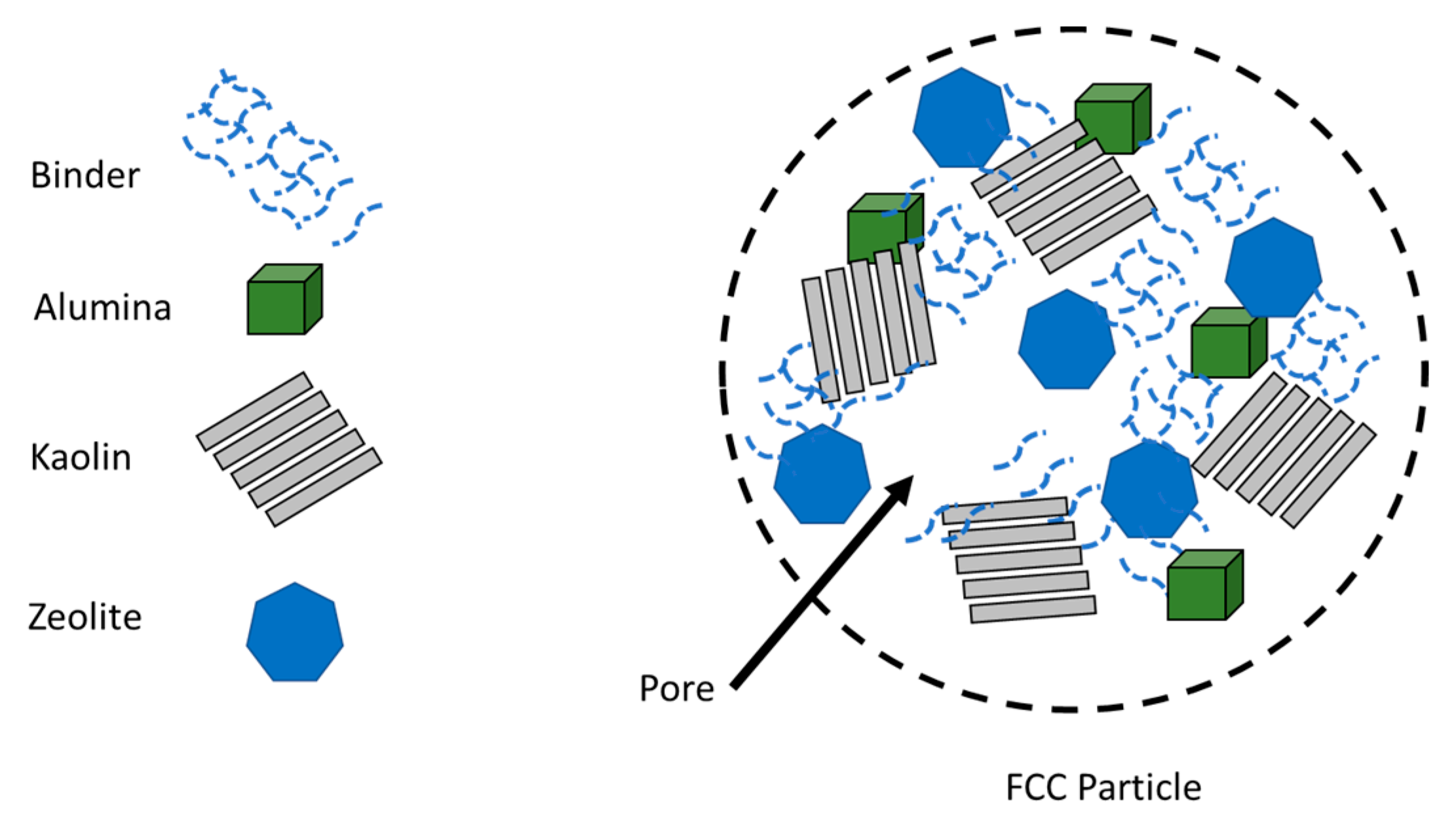
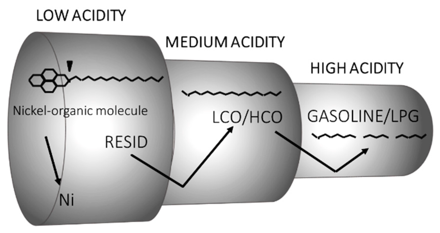
Figure 7 (adapted from Vogt et al. [
3]) schematically depicts the pore system in FCC catalysts.
The pores with different sizes are arranged in the ideal hierarchy, with the larger pore meeting the large molecules first. Furthermore, the distribution of acid sites should be aligned with pores of different accessibility. Narrow pores and high acidity are needed to crack small hydrocarbon molecules; conversely, bulkier molecules can be cracked in wider pores, whose acidity is lower.
4.5.1. Meso-Chemistry—A New Area of Investigation
In recent years there has been an interest in nanotechnology, where the control of events is in the atomic or molecular scale [
30,
37,
38,
39]. However, concerning reactions over an FCC catalyst, reactants must diffuse through a path length of 10 to 40,000 nm to reach the active sites and undergo cracking.
Noteworthy effects and functionalities that are important in macroscopic phenomena begin to manifest themselves and cannot be described only by laws of the atoms and molecules scale alone. This range can be named the mesoscale, and it works as a bridge between the nanoscale and the macroscale.
Consider the consecutive reaction A → B → C.
In nanoscale chemistry: For a given type of catalyst site, the distribution of products B and C (selectivity) is controlled by the extent of the reaction.
In mesoscale chemistry: product selectivity is also controlled by the catalyst’s accessibility. If Catalyst 1 and Catalyst 2 have the same type of active sites, but different accessibility, they will yield different product distributions at the same degree of conversion of A. This is a usual phenomenon in FCC.
Accessibility is intrinsically affected by pore connectivity and tortuosity. Connectivity can be defined as the number of pores intersecting at a node [
49]. The pore system in an FCC catalyst particle forms a network of pores that intersects in nodes and connects to each other and to the particle’s surface.
Two particles may have the same pore size distribution and still different accessibilities. During a reaction, the reactant can reach the active site of one catalyst in a shorter time than the other, i.e., one catalyst can be more accessible than the other if the time spent for the reactant to reach the catalyst sites—and products to leave—is shorter. The origin of the improved performance is directly linked to the existence of interconnected networks of micro- and mesopores [
50]. This comparison has important catalytic consequences, not only on the reaction rate but also on the selectivity of more complex reactions and further on the catalyst deactivation and life.
The direct participation of macro- and mesopores in the kinetics of adsorption indicates that their role in facilitating molecular diffusion is more substantial than shortening the micropores’ diffusion path.
4.5.2. Characterization of Accessibility
Although physical properties such as mesoporosity have been recognized as important, little significant attention has been paid to the influence of mass transfer barriers caused by various manufacturing processes and those induced by a few contaminants in the performance of FCC catalysts. Such barriers are significant in short contact time FCCU [
4].
Nitrogen or argon physisorption and mercury penetration porosimetry are employed to obtain average textural properties and pore size distribution (PoSD) but offer limited information on pore connectivity. Three-dimensional (3D) information from X-ray Micro-Computed Tomography (μ-CT) or Electron Tomography (ET) can determine the structural parameters and help visualize the porous structure [
51,
52].
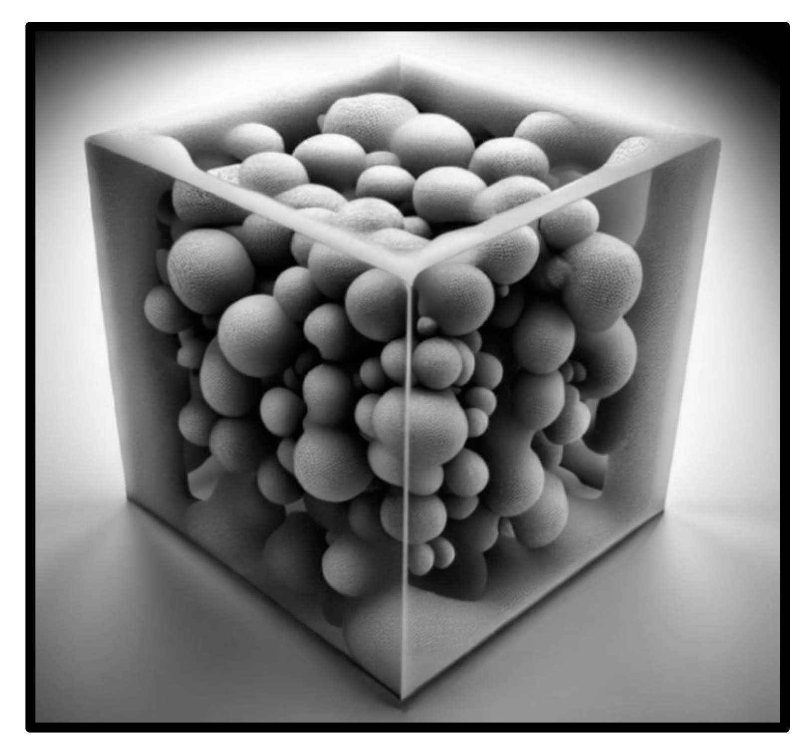
Figure 8 is a 3D reconstruction of an X-ray μ-CT image showing interconnected, isolated, and surface-bound porosity in a catalyst control volume (model developed by the author with the use of artificial intelligence tools (Bing Image Creator), [
53]). The more the main network of pores connects to the catalyst surface porosity, the higher the connectivity (and accessibility).
Other methods to assess pore connectivity include NMR cryodiffusometry, hyperpolarized 129Xe NMR, and Small-Angle X-Ray Scattering (SAXS), to name a few:
- -
Cryoporometry (thermoporometry) is a technique used to determine pore size distributions of solids. It is based upon the phenomenon that the melting or freezing point of a fluid imbibed within a porous solid is depressed below that of the bulk solid by an amount inversely proportional to pore size [
54]. Water, cyclohexane, and benzene are common probe fluids used in cryoporometry: their choice is limited by criteria such as the requirement that no part of the sample be soluble in the probe fluid. The cryoporometry technique can be performed using either NMR spectroscopy (NMR cryodiffusometry) or calorimetry.
- -
129Xe NMR allows probing pore sizes and pore connectivity or pore-blocking. These parameters make the technique particularly interesting for investigating hierarchical functional materials on different length scales. Obtaining sufficient signal intensity in a reasonable experimental time remains a limitation of the method, which can be overcome by hyperpolarization techniques [
55].
- -
3D imaging in a transmission electron microscope is called electron tomography (ET). Transmission images of the sample acquired from at least a hundred different angles can be reconstructed into a 3D model of the sample. This technique has a very high resolution (tens of nanometers) but is only suitable for tiny samples [
56].
- -
Computed tomography (CT) is a non-destructive 3D imaging technique based on the different X-ray attenuation of materials. Its non-destructive nature allows temporal investigation (4D imaging, where the fourth dimension is time), and the examined samples remain unchanged, can be further investigated (even in situ), or can be used. Virtually no sample preparation is required. The main limitations of CT are related to the high Z (atomic number) contrast necessary for good imaging quality. Low-Z materials and samples with low X-ray attenuation contrast are challenging to measure, whereas very high Z materials (e.g., metals) can introduce severe artifacts and worsen image quality. Micro-CT (μ-CT) stands for high-resolution CT. With the decrease in focal spot size and increased resolution, developers could achieve submicron resolution and started referring to devices capable of this high resolution as nano-CT. After some time, with the use of synchrotron radiation and special X-ray optics, even better resolution (below 100 nm) became obtainable [
56].
- -
Small-angle X-Rays scattering (SAXS) technique uses X-ray beams to penetrate the materials and obtain information on the pore structure by measuring the intensity of scattered radiation within a specific range of scattering angles (0.1 to 5°). It is a non-destructive measurement of the total porosity, including both open and closed pores, providing information on pores from angstrom to micron scales (from ca. 5 Å to 20 μm) [
57]. In mercury porosimetry, the lower limit of the detectable pore throat is approximately 3 nm, whereas the helium pycnometry method can obtain gas-accessible porosity but not total porosity; the SAXS method, on its part, includes both accessible (open) and inaccessible (closed) porosity—although this is not a relevant information for catalytical purposes.
4.5.3. Accessibility Effect on Catalytic Performance: Relevance to FCC
On the Rate of Reaction
The nature of the porous structure of the catalyst particle should be examined closely because diffusion to and from the catalytic sites is essential in determining the overall reaction rate. Materials and methods of catalyst manufacturing can dramatically affect the porous structure. In addition to the distribution of pore sizes, their shape can also be relevant [
4]. Aside from the idealized arrangement of pores presented in
Figure 7, for the reactants to reach the interior of the catalyst particle they must pass through the surface, so diffusional restrictions must be minimized in the boundary layer.
On the Reaction Selectivity
The importance of diffusion for a simple reaction has been presented in previous sections. In the FCC process, the reactions to consider are more complex since the cracking of heavy molecules of the feed will undergo further reactions.
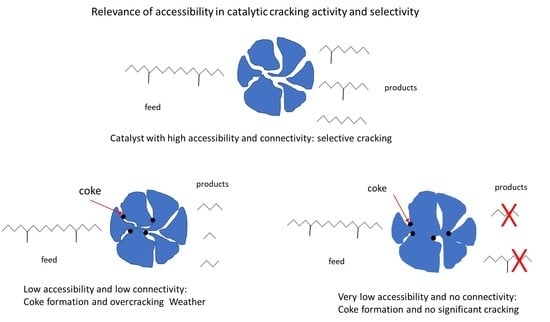
Hence, the immediate observation is that reaction products must diffuse out of the catalyst particle quickly enough to prevent overcracking to unwanted light products.
Coke and heavy metals deposition on the FCC catalyst can cause fouling and pore-mouth plugging. Fouling can change pore architecture and cause significant differences in catalyst selectivity, whereas pore plugging reduces the accessibility of the catalyst matrix.
Furthermore, we could generalize and consider the effect of accessibility on the selectivity of sequential reactions , where k1 and k2 are catalytic reaction-rate constants. In the absence of diffusional resistance, the ratio of the reaction-rate constants gives an intrinsic yield. On the other hand, if the two consecutive reactions are highly influenced by diffusional resistances, there will be a remarkable yield reduction.
On the Catalyst Acidity
The relationship between acidity and accessibility should be discussed with different approaches, namely at the catalyst-preparation level (ingredients and compounding) and the catalyst application.
- -
At the ingredient level: Zeolite micropores pose the main restriction to diffusion in a catalyst, and the ways to increase it belong to the nanoscale manipulation. Soft or hard templates can be added to the zeolite synthesis to introduce mesopores, thus increasing accessibility to the zeolite active (acid) sites located in the framework (bottom-up methods). Virtually the same framework composition as the strictly microporous reference zeolite can be obtained; hence, the mesoporous zeolite will bear the same acidity in terms of number and strength as the reference material.
Top-down methods, on the other hand, create mesopores at the cost of micropores destruction. They involve dealumination or desilication. In both cases, acidity will change, reflecting the framework composition change (higher or lower SAR).
- -
At the catalyst assembling level: A more accessible zeolite does not mean a more accessible catalyst. It is useless to embed a hierarchical zeolite if the large molecules of the feed cannot reach the crystal. The key to accessibility increase lies in the compounding technology, the way the ingredients are packed, arranged, and bound in the catalyst particle. Here we deal with mesoscale phenomena, in which the extent of macroscale mass transfer within the catalyst pore network will change the product yield and selectivity.
- -
During catalyst application/operation: Calcium and heavy metals contaminants (iron, nickel, vanadium) present in crude oils as porphyrins, naphthenates, or inorganic compounds can deposit on the FCC catalyst surface during cracking and destroy the crystalline structure, block pore channels, and cover the catalyst’s active sites. The catalyst’s selectivity and activity decrease, and coke and dry gas yield are higher with a simultaneous decrease in liquid fuel yield [
58].
Yuxia et al. [
58] have impregnated FCC catalysts with two kinds of iron (Fe) species (iron chloride and iron naphthenate) to simulate contamination sources from FCC feedstocks. Fresh FCC catalyst and Fe-contaminated samples were steam-deactivated, and their performance was carried out on an ACE unit.
The contamination of iron chloride showed little influence on the catalyst performance, while the activity of the catalyst contaminated with iron naphthenate decreased with increasing iron content.
Scanning Electron Microscopy with Energy Dispersive X-Ray Analysis (SEM-EDAX) revealed that the distribution of iron on the surface of the catalyst contaminated with iron chloride is uniform, and the Fe contents in the exterior and interior of the catalyst particles are close, suggesting the absence of local enrichment of Fe deposits. The catalyst contaminated using iron naphthenate presented a non-uniform iron distribution, with the Fe content in the exterior of the FCC particle markedly higher than that in its interior.
The total acidity of the Fe-contaminated samples was measured with NH3-TPD methods, and the results were compared with the fresh catalysts. The authors noticed significant acidity loss in Fe naphthenate-contaminated catalysts and that acidity loss is negligible when Fe chloride is used.
On the Catalyst Life
Various contaminants are less widely recognized and studied regarding their effects on the FCC process. Fe and Ca probably have little inherent catalytic activity but have been associated with surface deposits that clearly could have a significant impact on the access to the interior of an FCC catalyst particle [
33].
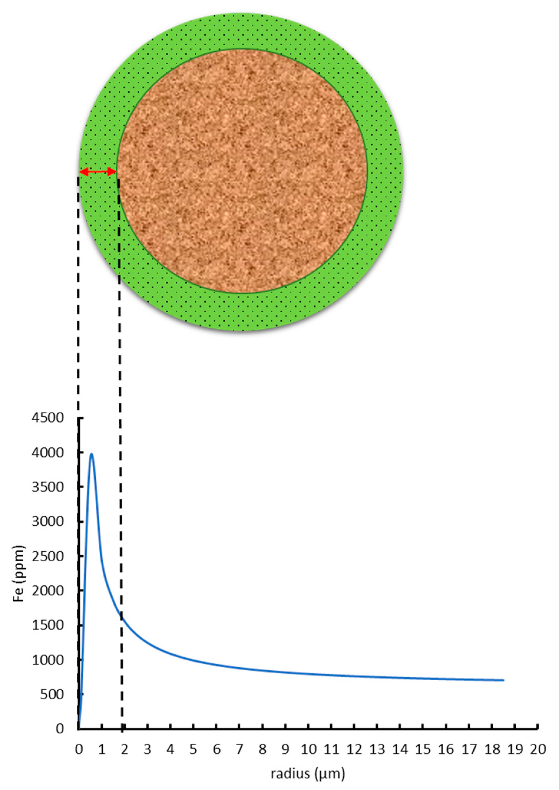
Weckhuysen et al. [
3,
59,
60] characterized commercial e-cats and artificially deactivated and metalated catalysts using the techniques of X-ray micro- and nano-tomography, as well as μ-XRF and μ-XRD. They have concluded that both contaminant metals Fe and Ni gradually incorporate almost exclusively near the external surface regions of the FCC catalyst particles in a shell not thicker than 2 μm, represented by the green annulus in
Figure 9 (adapted from [
59]), thus severely limiting the macropore accessibility as metal concentrations increase.
The authors [
59] carried out a catalyst performance test (ACE) on the e-cats with different metal levels using VGO at a cracking temperature of 538 °C and at different catalyst-to-oil (CTO) ratios: 3, 4, 5, and 6. ACE results show a clear correlation between catalyst deactivation/age (and therefore the levels of Ni and Fe in the sample) and catalytic activity: the older the catalyst, the lower the bottoms conversion.
Pore-blocking prevents feedstock molecules from reaching the catalytically active sites. Consequently, metal deposition reduces the catalytic conversion with increasing time on stream because although the internal pore system remains unobstructed, it becomes mostly inaccessible.
Commercial FCC unit yields are directly related to accessibility.
Figure 10 and
Figure 11 (adapted from [
61], used under permission of Albemarle Co., Charlote, NC, USA) show the increase in conversion and gasoline yield as the catalyst ages in a commercial FCCU [
61].
Nickell [
14] has documented commercial cases illustrating a tangible correlation between AAI and unit performance.
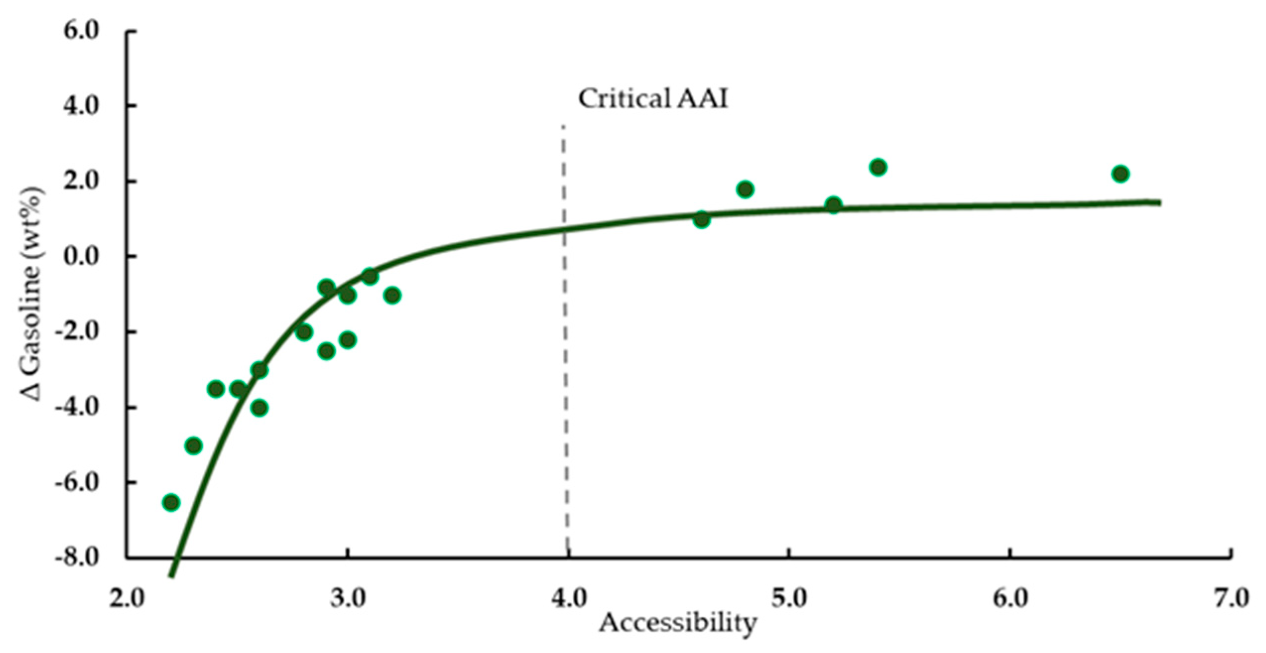
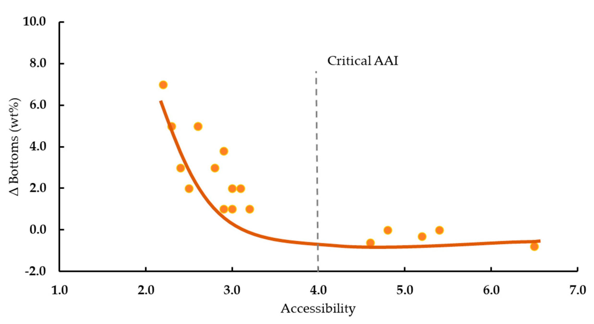
Figure 12 (adapted from [
14], used under permission of Albemarle Co.) shows the decrease in activity (bottoms conversion) as the catalyst ages in the FCCU, with the consequent decrease in accessibility. It is noticeable that the catalyst fell below the refiner’s “critical AAI”; a point where the bottoms increased remarkably as the conversion correspondingly decreased.
Empirical observations consistently demonstrate that many refiners experience a “critical accessibility level”. This critical level is extremely unit-specific and is a function of feed quality, feed–catalyst contact efficiency, riser residence time, equilibrium catalyst metal levels, and regenerator conditions. Operating with accessibility levels below this point results in significant losses in FCC unit conversion and transportation fuel production. This observation does not show in traditional equilibrium catalyst laboratory testing [
61].
4.6. Attrition Resistance × Accessibility
FCC catalyst assembly is the art and technique of combining different materials into a single composite designed to have the desired physicochemical characteristics and catalytic performance. The binder surrounds the ingredient particles and holds them together by their contact points [
3]. Water—and eventually some other volatile matter—evaporates in the drying process, leaving voids in the interstices of the particles that form a secondary pore system, mainly in the meso- and macro-regions.
As the porosity of the microsphere increases, however, the rate at which it fractures and wears down to finer particles within the FCCU increases, resulting in increased particulate emission from the unit and higher demand for fresh catalyst addition rates. Composition or processing procedures to reduce the rate at which an FCC catalyst wears for a given total pore volume are of fundamental importance to improve the performance of the catalyst [
6].
Pore volume in the micro (<2 nm) range is known to yield increased coke. Mesopores (2–50 nm) play a significant role in catalytic reactions, by improving coke selectivity and macropores (50–1000 nm) will serve as conveyors for bulky reactants, thus enabling short contact reaction times [
6].
The increase in mesopore volume is directly related to the higher accessibility. Mesopores ensure optimal accessibility and transport of reactants and products, while zeolite micropores induce the preferred shape-selective properties [
62].
The amount of binder is capital for the physical properties of the catalyst, and it should be balanced to account for the best match of accessibility and attrition resistance [
11]. Higher binder intake improves the catalyst’s mechanical strength (lower AI), but its nanoparticles can fill some of the zeolite micropores rendering them useless for the cracking reactions. Conversely, too little binder is deleterious to adhesion, which increases the attrition index (AI) and causes catalyst losses to be high in the FCCU.
In general, accessibility and mechanical resistance are two desirable features of the catalysts. Nevertheless, in preparation, a parameter that favors one typically disfavors the other. In the next section, we will examine methods of increasing FCC catalyst accessibility but also examine their side effects on other catalyst properties, especially on the mechanical resistance.
4.7. Methods to Increase FCC Catalyst Accessibility
Although the chemistry in the mesoscale is rather complex, attempts to modify the accessibility in the FCC catalyst can be even more challenging since compounding systems are very heterogeneous.
Increasing mesoporosity in the zeolite system belongs to the nanoscale manipulation, and it has been dealt with in many publications in the open literature [
31,
37,
38,
63,
64,
65,
66]. In contrast, the modification of catalyst pore structures and their connectivity are limited to patent publications. Furthermore, the comparison between these approaches is scanty, and the effects of manipulations are not tackled on a scientific basis.
Accessibility can increase using pore engineering methods, including modifications in the steps of:
Synthesis or modification of precursors (precipitation, acid/base treatments, hydrothermal processes).
Drying of the Catalyst Precursor Slurry, by reducing the surface tension of the solvent (soft templating).
Catalyst compounding, such as ingredients with larger average particle size; aging of the binding species; addition of a solid porogenic agent, which is later removed, and leaves empty spaces in the matrix (hard templating).
Ingredients with larger average particle sizes will contribute only marginally to the increase in accessibility and bear a high risk of increasing the attrition index.
Aging of the binding system through pH change or temperature increase will cause its particles to increase their size faster by polymerization [
67], which is ultimately the same effect described above, with the same risks of increasing the attrition index.
In the soft templating strategy, interparticle mesopores can be introduced in the catalyst matrix by the action of surfactant molecules that avoid shrinkage and collapse of the pores during particle formation. A well-known problem is the shrinkage of gels during drying due to the capillary force arising at the hydrophilic surface of the gels and solvent. To minimize the capillary force, modifying sols with organic species renders the surface hydrophobic to prevent shrinkage [
68]. In the early drying stage, the gel (matrix) shrinks with the decrease of the liquid volume in the pore. Then, after the liquid leaves the pores, the capillary forces disappear, and the volume of the matrix comes back almost to the same volume as the wet gels (spring back effect), resulting in highly porous xerogels (ambient pressure aerogels).
A variation of the soft templating in FCC catalyst production relies on the addition of species that can be decomposed in the drying step, producing gases that will force their way out of the catalyst and minimize the formation of the hard silica shell.
Hard (or solid) templating techniques use a template or filler (Pore-Regulating Agent, PRA) that remains in the solid state throughout the whole preparation process of the catalyst, after which it can be removed, thus creating large pores. The choice of PRA should consider the following criteria: (i) their surface properties should be compatible with the chemical properties of the ingredients (mainly the binding system), (ii) they should be stable at the compounding conditions (temperature and pH), and (iii) the remaining catalyst structure should be stable after removal of the hard template [
30].
The addition of PRAs presents itself as a safer and more efficient way to increase accessibility with little or no damage to AI [
69]. In this context, PRAs are defined as additives embedded into an inorganic matrix and afterward washed or burned out to generate meso- and/or macropores. They have been extensively used to control the pore structure of catalyst supports, mainly in the development of hydroprocessing catalysts, which usually require a bimodal distribution with a certain percentage of macropores to allow for the internal diffusion of heavy molecules [
69].
Carbon black and crystalline cellulose are the combustible materials most often used as pore generator additives. Other materials such as active carbon, wood flour, sugar, starch, and several polymers have also been reported.
4.8. Pore-Regulating Agents (PRA)
Embedding combustible fillers in inorganic matrices and burning out their carbonaceous matter leaves a void, thus generating pores. A direct correlation, for instance, has been found between carbon black particle diameter and the size of the pores generated. A wide range of PRAs to manufacture fixed-bed catalysts has been reported in the literature (
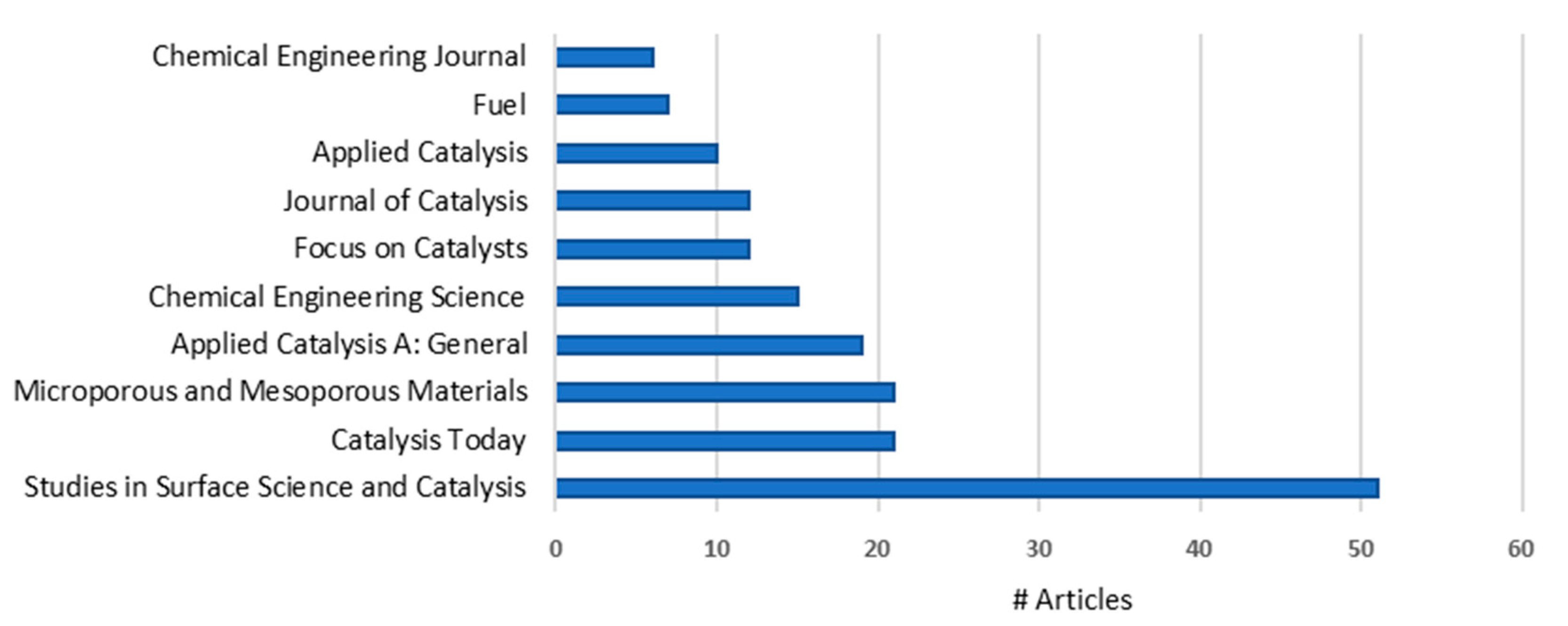
Table 7).
Pore Size Distribution (PoSD) of FCC catalysts that use silica as the binder is very dependent on the content of each component. Increasing zeolite content leads to an increase in the macropore region, whereas the increase of alumina or silica binders leads to a decrease. In contrast, using these PRAs should allow the control of the PoSD, regardless of FCC catalyst formulation [
69].
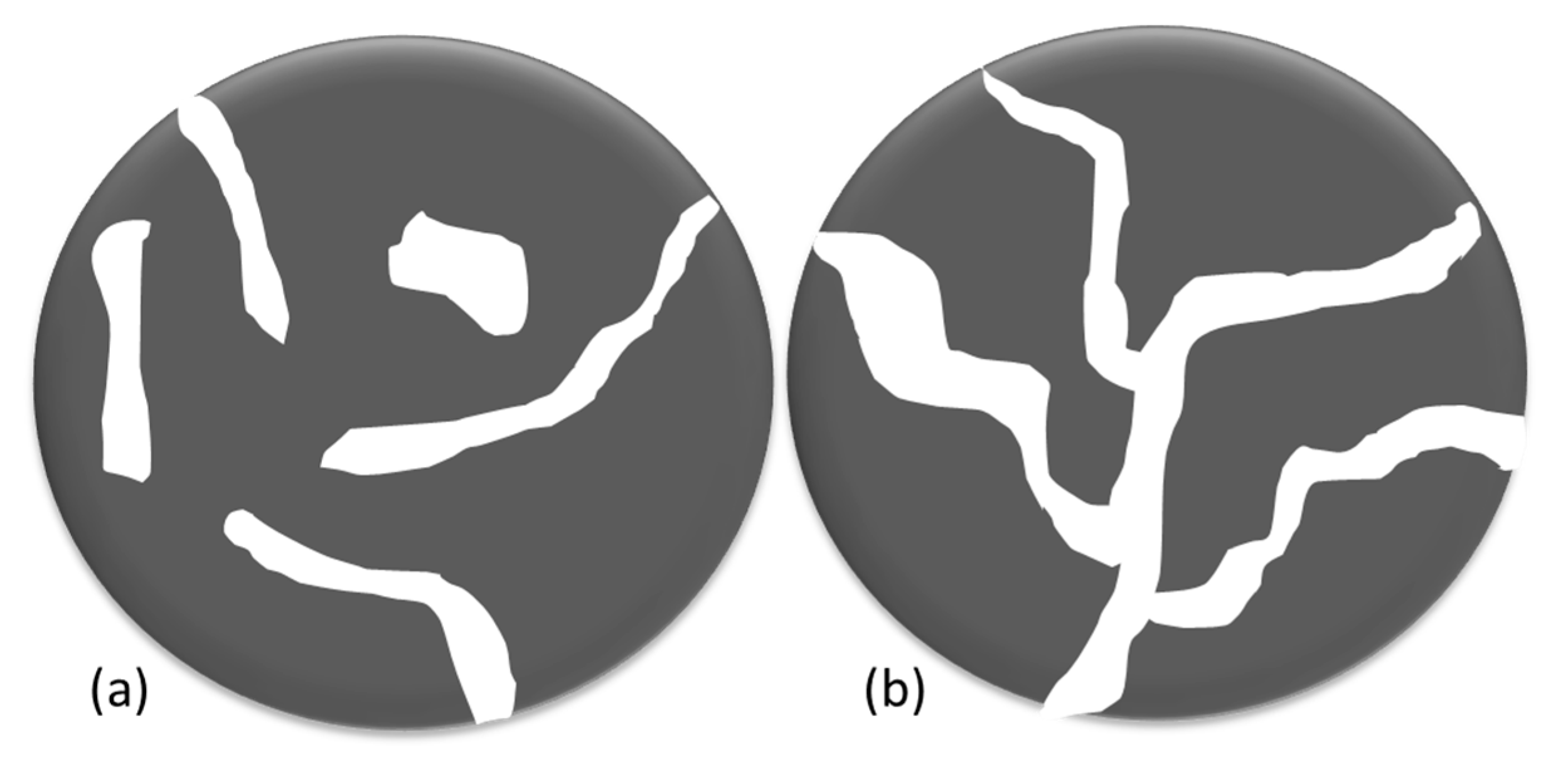
Even though pore size distribution may not be the ultimate method to compare the accessibility of different catalysts, it can still furnish leads. This is the case when the catalyst-preparation methods provide sufficient connectivity between larger pores, so the diffusion to the external surface of the catalyst is typically governed by parameters such as the mean pore diameter. Two catalysts may have the same mesopore area and almost similar pore size distribution, still, the extension of connectivity can render their accessibilities very much different from one another (
Figure 13).
Pores connectivity and their hierarchy are the keys to accessibility. The choice of PRA and the strategy of addition affect connectivity. Typical methods that employ combustible PRAs may give rise to closed or dead-end pores that do not connect to the outer side of the catalyst and lead to the poorest case of accessibility.
If one employs methods such as the decomposition (gasification) of added chemicals, the final structure will most probably contain escape routes for the products of the PRA decomposition, which result in connectivity to the external surface (situation b) instead of (a) in
Figure 13.
At any rate, precaution must be taken to ensure that the larger pores formed are connected hierarchically to narrower pores and the catalyst surface.

 ,
, 


