
Effect of MgFe-LDH with Reduction Pretreatment on the Catalytic Performance in Syngas to Light Olefins

Abstract
:1. Introduction
2. Results and Discussion
2.1. Catalyst Characterization
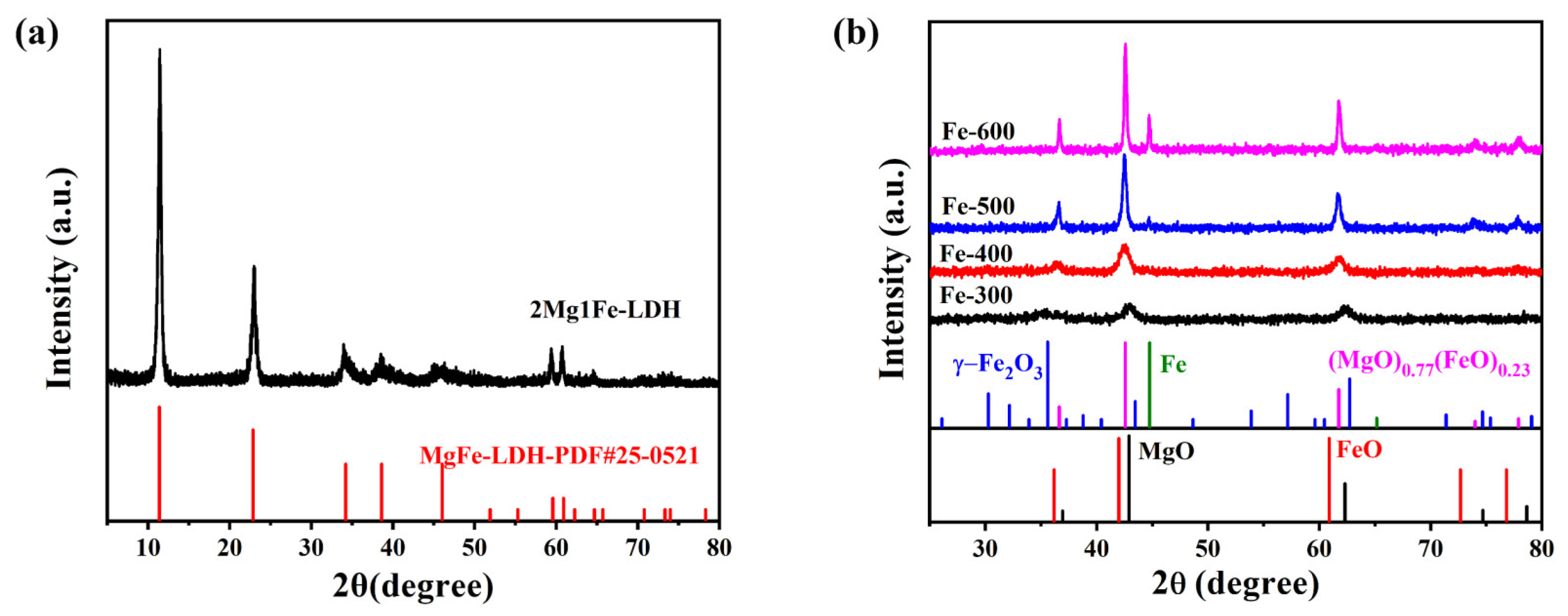
2.1.1. Crystalline Structure
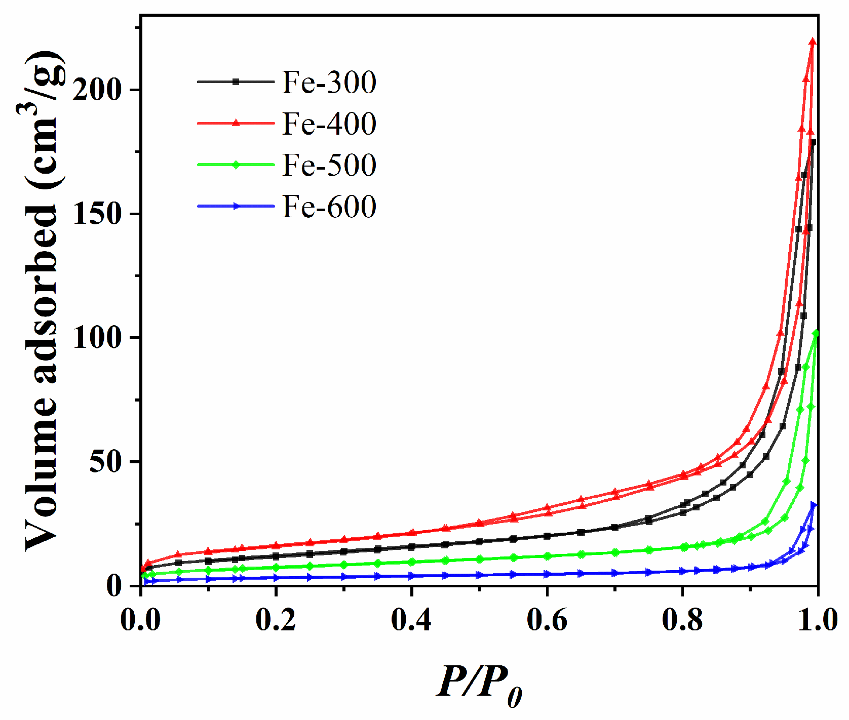
2.1.2. Textural Properties
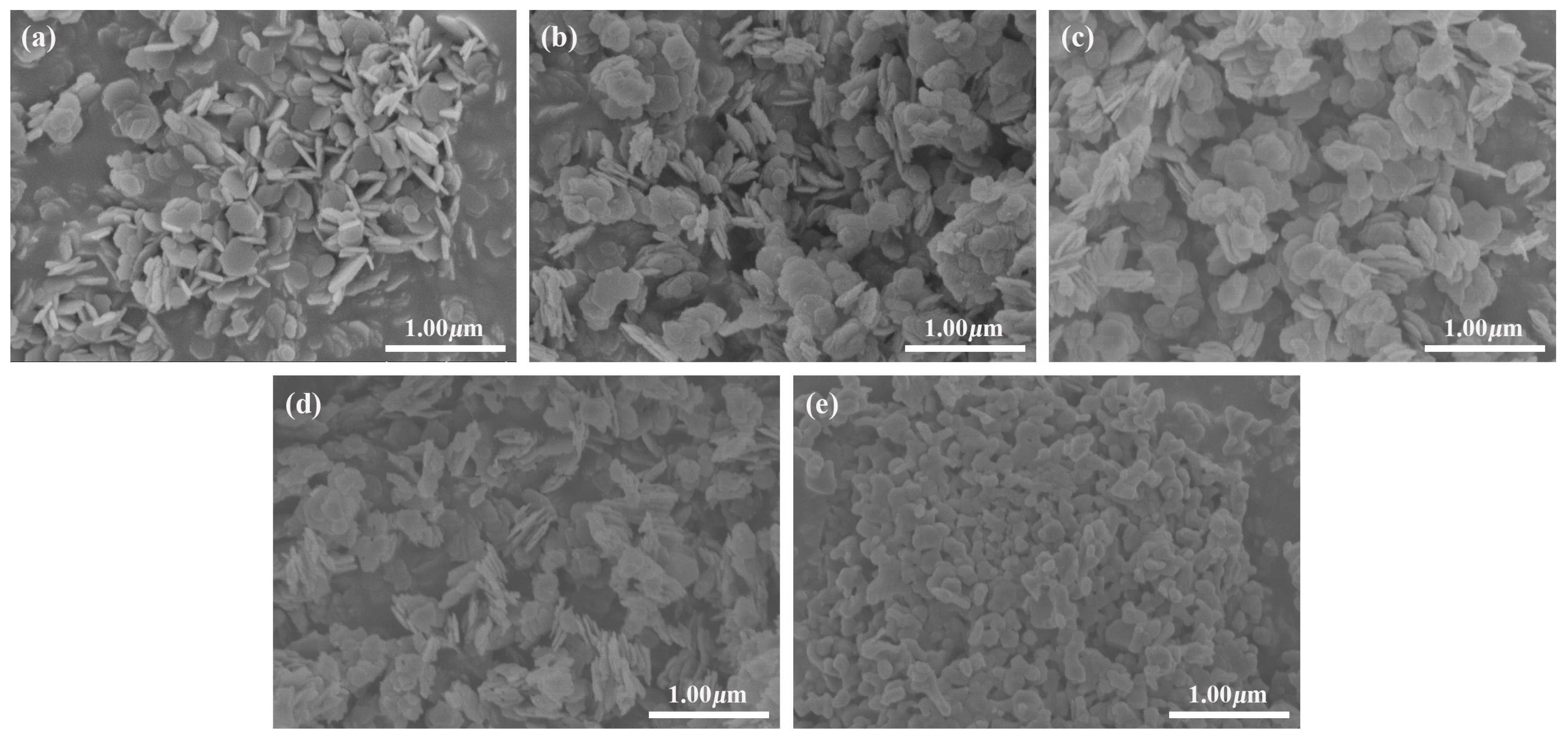
2.1.3. SEM Analysis
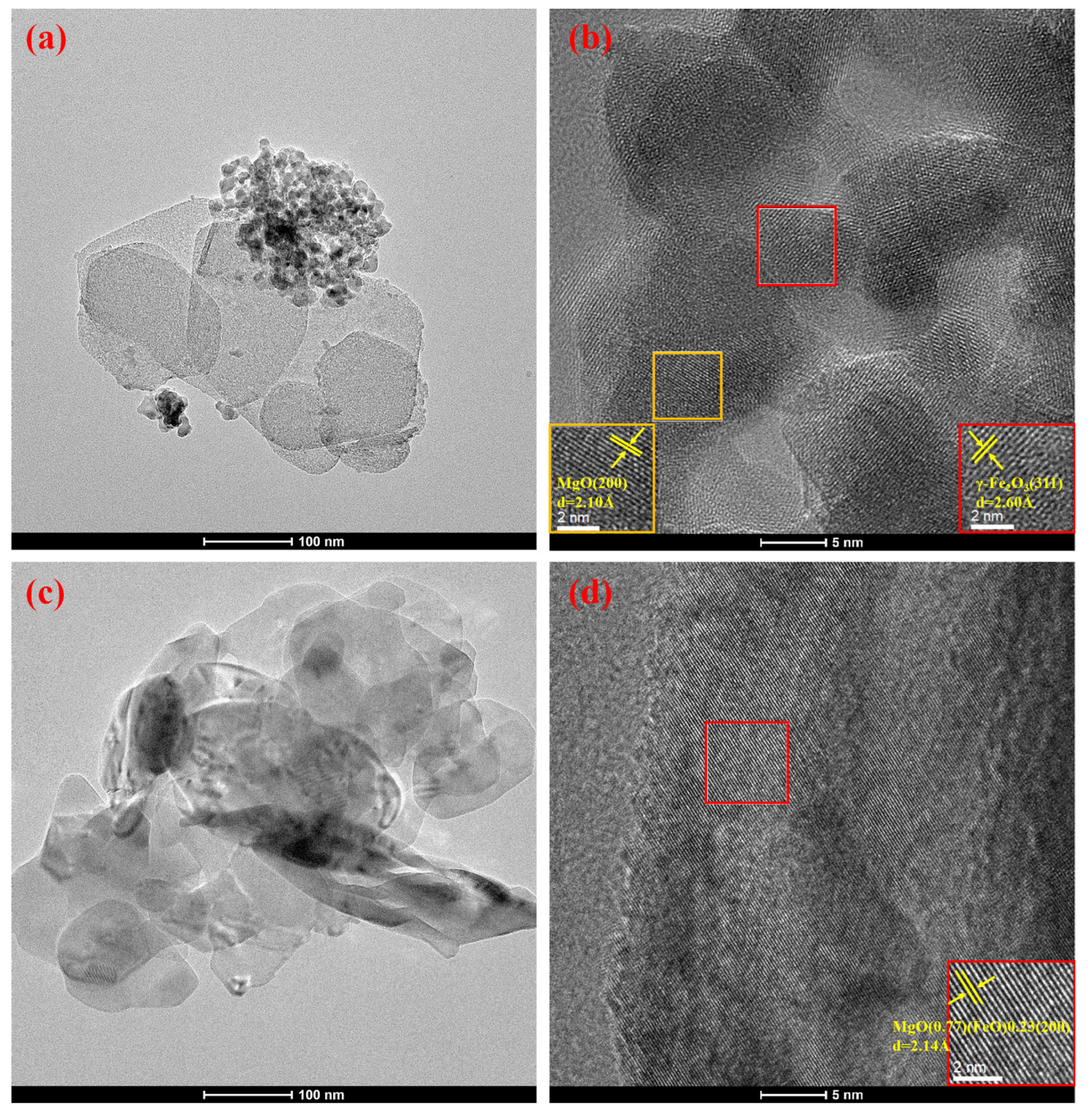
2.1.4. TEM Analysis
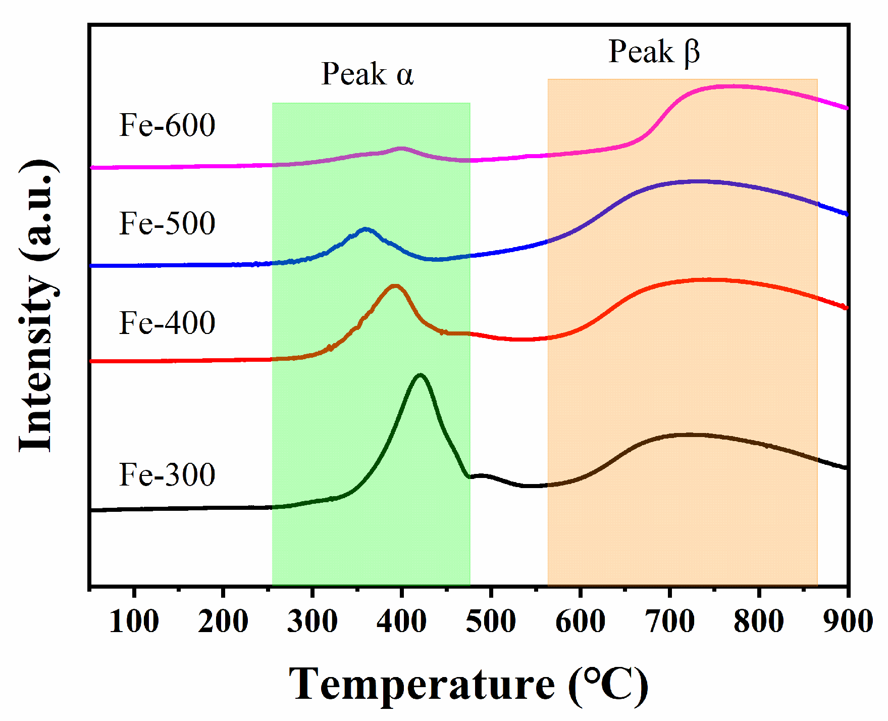
2.1.5. H2-TPR Measurement of the Catalysts
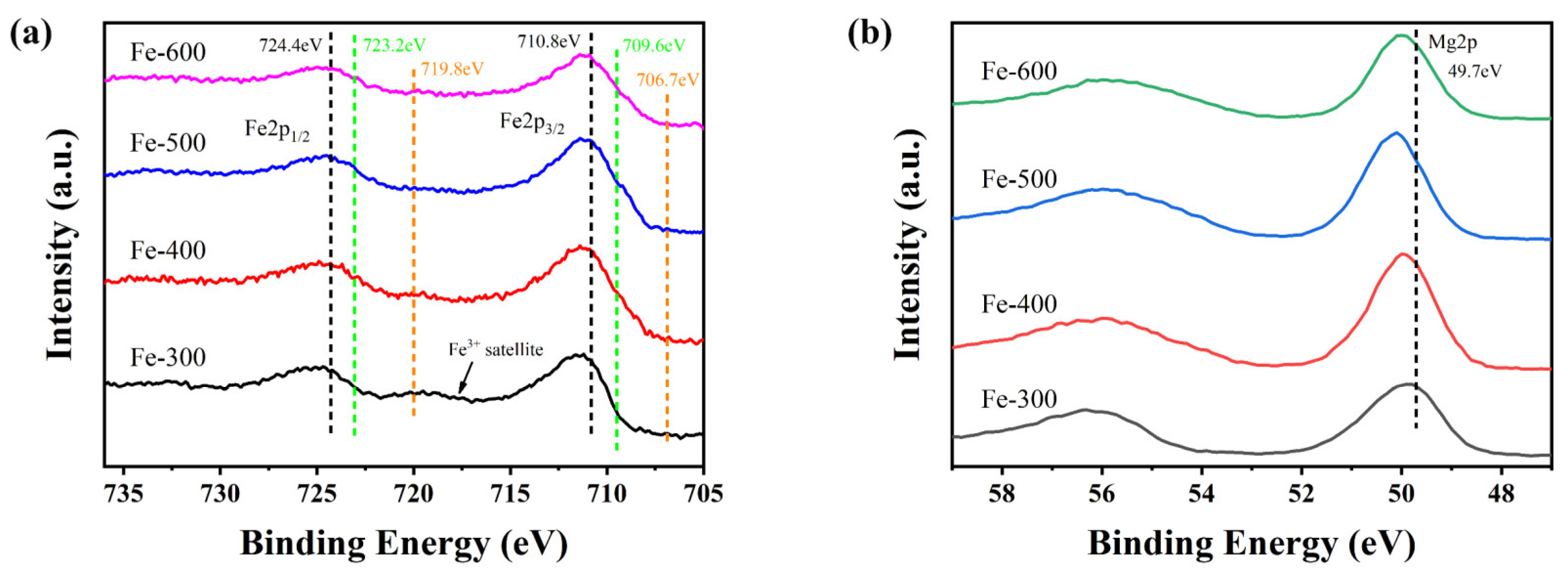
2.1.6. XPS Analysis of the Catalysts
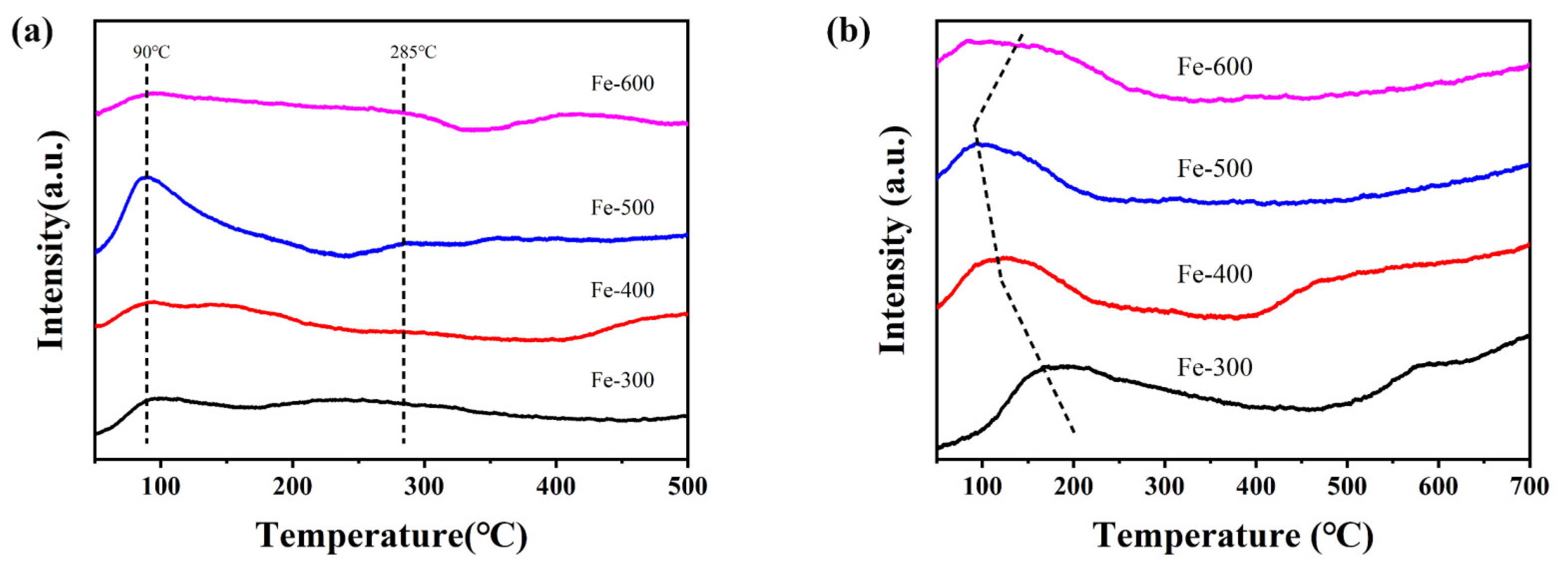
2.1.7. Chemisorption Properties of the Catalysts
2.2. Catalytic Performance
2.2.1. The Activity and Selectivity of the Catalysts
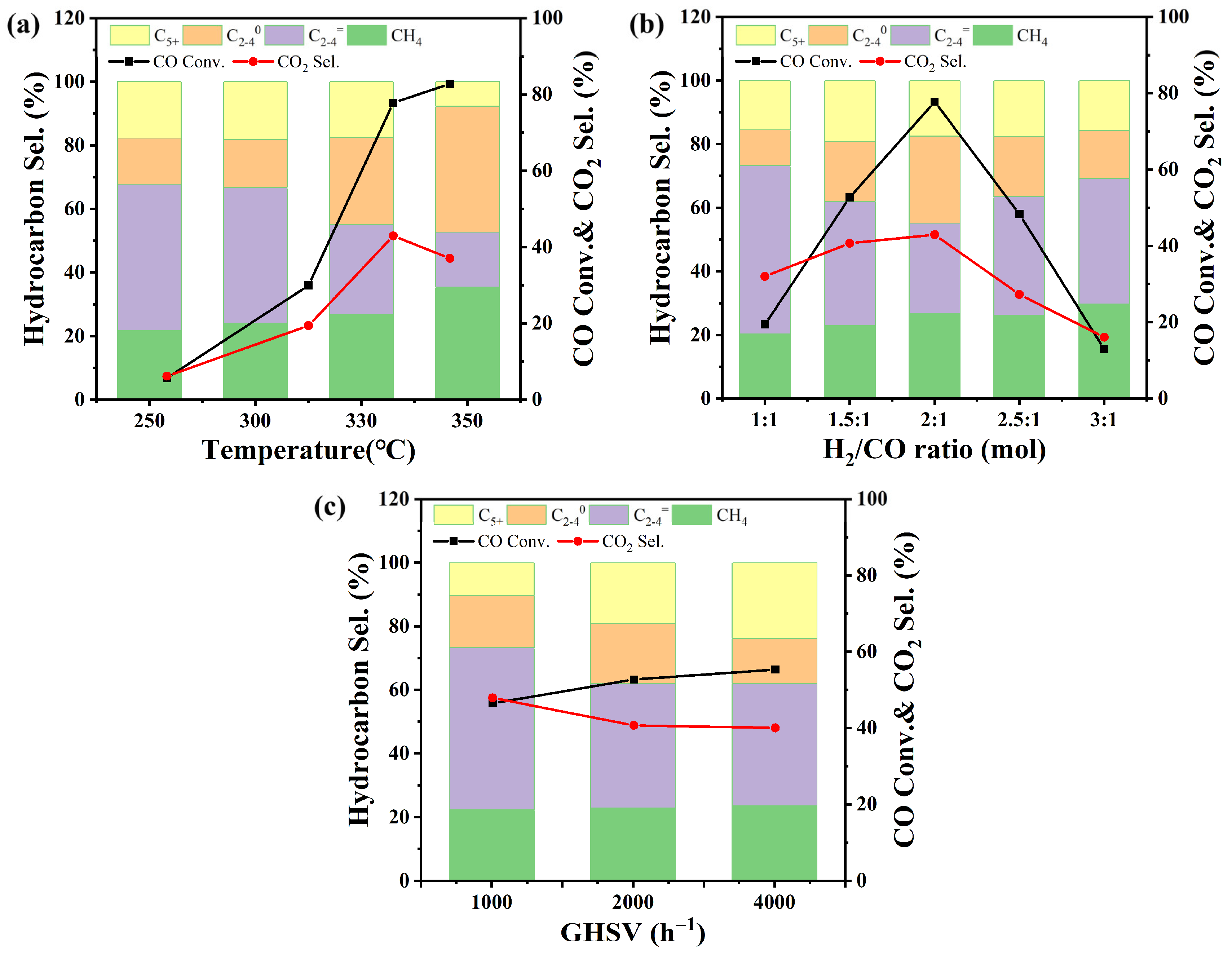
2.2.2. The Effects of the Reaction Conditions over the Fe-500 Catalyst
3. Materials and Methods
3.1. Catalyst Preparation
3.1.1. Synthesis of the MgFe-CO3-LDH Precursor
3.1.2. Synthesis of Fe-X Catalysts
3.2. Catalyst Characterization
3.3. Catalytic Activity Tests
4. Conclusions
Supplementary Materials
Author Contributions
Funding
Data Availability Statement
Conflicts of Interest
References
- Corma, A.; Melo, F.; Sauvanaud, L.; Ortega, F. Light cracked naphtha processing: Controlling chemistry for maximum propylene production. Catal. Today 2005, 107, 699–706. [Google Scholar] [CrossRef]
- Torres Galvis, H.M.; Bitter, J.H.; Davidian, T.; Ruitenbeek, M.; Dugulan, A.I.; de Jong, K.P. Iron Particle Size Effects for Direct Production of Lower Olefins from Synthesis Gas. J. Am. Chem. Soc. 2012, 134, 16207–16215. [Google Scholar] [CrossRef] [PubMed] [Green Version]
- Snel, R. Olefins from Syngas. Catal. Rev. Sci. Eng. 1987, 29, 361–445. [Google Scholar] [CrossRef]
- Yang, Z.; Pan, X.; Wang, J.; Bao, X. FeN particles confined inside CNT for light olefin synthesis from syngas: Effects of Mn and K additives. Catal. Today 2012, 186, 121–127. [Google Scholar] [CrossRef]
- Chen, X.; Deng, D.; Pan, X.; Hu, Y.; Bao, X. N-doped graphene as an electron donor of iron catalysts for CO hydrogenation to light olefins. Chem. Commun. 2014, 51, 217–220. [Google Scholar] [CrossRef]
- Torres Galvis, H.M.; de Jong, K.P. Catalysts for Production of Lower Olefins from Synthesis Gas: A Review. ACS Catal. 2013, 3, 2130–2149. [Google Scholar] [CrossRef]
- Puskas, I.; Hurlbut, R.S. Comments about the causes of deviations from the Anderson–Schulz–Flory distribution of the Fischer–Tropsch reaction products. Catal. Today 2003, 84, 99–109. [Google Scholar] [CrossRef]
- Galvis, H.M.T.; Bitter, J.H.; Khare, C.B.; Ruitenbeek, M.; Dugulan, A.I.; de Jong, K.P. Supported Iron Nanoparticles as Catalysts for Sustainable Production of Lower Olefins. Science 2012, 335, 835–838. [Google Scholar] [CrossRef] [Green Version]
- Krishnamoorthy, S.; Li, A.; Iglesia, E. Pathways for CO2 Formation and Conversion During Fischer–Tropsch Synthesis on Iron-Based Catalysts. Catal. Lett. 2002, 80, 77–86. [Google Scholar] [CrossRef]
- Botes, F.G. Water–gas-shift kinetics in the iron-based low-temperature Fischer–Tropsch synthesis. Appl. Catal. A Gen. 2007, 328, 237–242. [Google Scholar] [CrossRef]
- Pirola, C.; Bianchi, C.L.; Di Michele, A.; Vitali, S.; Ragaini, V. Fischer Tropsch and Water Gas Shift chemical regimes on supported iron-based catalysts at high metal loading. Catal. Commun. 2009, 10, 823–827. [Google Scholar] [CrossRef]
- Zhong, L.; Yu, F.; An, Y.; Zhao, Y.; Sun, Y.; Li, Z.; Lin, T.; Lin, Y.; Qi, X.; Dai, Y.; et al. Cobalt carbide nanoprisms for direct production of lower olefins from syngas. Nature 2016, 538, 84–87. [Google Scholar] [CrossRef]
- Wang, J.; Xu, Y.; Ma, G.; Lin, J.; Wang, H.; Zhang, C.; Ding, M. Directly converting syngas to linear α-olefins over core-shell Fe3O4@MnO2 catalysts. ACS Appl. Mater. Interfaces 2018, 10, 43578–43587. [Google Scholar] [CrossRef]
- Santos, V.P.; Wezendonk, T.A.; Jaén, J.J.D.; Dugulan, A.I.; Nasalevich, M.A.; Islam, H.-U.; Chojecki, A.; Sartipi, S.; Sun, X.; Hakeem, A.A.; et al. Metal organic framework-mediated synthesis of highly active and stable Fischer-Tropsch catalysts. Nat. Commun. 2015, 6, 6451. [Google Scholar] [CrossRef] [Green Version]
- Wang, C.; Pan, X.; Bao, X. Direct production of light olefins from syngas over a carbon nanotube confined iron catalyst. Chin. Sci. Bull. 2010, 55, 1117–1119. [Google Scholar] [CrossRef]
- Chen, X.; Deng, D.; Pan, X.; Bao, X. Iron catalyst encapsulated in carbon nanotubes for CO hydrogenation to light olefins. Chin. J. Catal. 2015, 36, 1631–1637. [Google Scholar] [CrossRef]
- Jiao, F.; Li, J.; Pan, X.; Xiao, J.; Li, H.; Ma, H.; Wei, M.; Pan, Y.; Zhou, Z.; Li, M.; et al. Selective conversion of syngas to light olefins. Science 2016, 351, 1065–1068. [Google Scholar] [CrossRef]
- Cheng, K.; Gu, B.; Liu, X.; Kang, J.; Zhang, Q.; Wang, Y. Direct and Highly Selective Conversion of Synthesis Gas into Lower Olefins: Design of a Bifunctional Catalyst Combining Methanol Synthesis and Carbon–Carbon Coupling. Angew. Chem. 2016, 128, 4803–4806. [Google Scholar] [CrossRef]
- Zhang, Y.; Ma, L.; Wang, T.; Li, X. MnO2 coated Fe2O3 spindles designed for production of C5+ hydrocarbons in Fischer–Tropsch synthesis. Fuel 2016, 177, 197–205. [Google Scholar] [CrossRef]
- Li, Z.; Liu, R.; Xu, Y.; Ma, X. Enhanced Fischer–Tropsch synthesis performance of iron-based catalysts supported on nitric acid treated N-doped CNTs. Appl. Surf. Sci. 2015, 347, 643–650. [Google Scholar] [CrossRef]
- Visconti, C.G.; Martinelli, M.; Falbo, L.; Infantes-Molina, A.; Lietti, L.; Forzatti, P.; Iaquaniello, G.; Palo, E.; Picutti, B.; Brignoli, F. CO2 hydrogenation to lower olefins on a high surface area K-promoted bulk Fe-catalyst. Appl. Catal. B Environ. 2017, 200, 530–542. [Google Scholar] [CrossRef]
- Li, S.; Krishnamoorthy, S.; Li, A.; Meitzner, G.D.; Iglesia, E. Promoted Iron-Based Catalysts for the Fischer–Tropsch Synthesis: Design, Synthesis, Site Densities, and Catalytic Properties. J. Catal. 2002, 206, 202–217. [Google Scholar] [CrossRef] [Green Version]
- Dictor, R.A.; Bell, A.T. Fischer-Tropsch synthesis over reduced and unreduced iron oxide catalysts. J. Catal. 1986, 97, 121–136. [Google Scholar] [CrossRef]
- Yang, Y.; Xiang, H.W.; Xu, Y.Y.; Bai, L.; Li, Y.W. Effect of potassium promoter on precipitated iron-manganese catalyst for Fischer–Tropsch synthesis. Appl. Catal. A Gen. 2004, 266, 181–194. [Google Scholar] [CrossRef]
- Zhang, J.-L.; Ma, L.-H.; Fan, S.-B.; Zhao, T.-S.; Sun, Y.-H. Synthesis of light olefins from CO hydrogenation over Fe–Mn catalysts: Effect of carburization pretreatment. Fuel 2013, 109, 116–123. [Google Scholar] [CrossRef]
- Lu, J.; Yang, L.; Xu, B.; Wu, Q.; Zhang, D.; Yuan, S.; Zhai, Y.; Wang, X.; Fan, Y.; Hu, Z. Promotion Effects of Nitrogen Doping into Carbon Nanotubes on Supported Iron Fischer–Tropsch Catalysts for Lower Olefins. ACS Catal. 2014, 4, 613–621. [Google Scholar] [CrossRef]
- Liu, Y.; Chen, J.-F.; Bao, J.; Zhang, Y. Manganese-Modified Fe3O4 Microsphere Catalyst with Effective Active Phase of Forming Light Olefins from Syngas. ACS Catal. 2015, 5, 3905–3909. [Google Scholar] [CrossRef]
- Zhuo, O.; Yang, L.; Gao, F.; Xu, B.; Wu, Q.; Fan, Y.; Zhang, Y.; Jiang, Y.; Huang, R.; Wang, X.; et al. Stabilizing the active phase of iron-based Fischer–Tropsch catalysts for lower olefins: Mechanism and strategy. Chem. Sci. 2019, 10, 6083–6090. [Google Scholar] [CrossRef] [Green Version]
- Niemelä, M.K.; Krause, A.O.I. Characterization of magnesium promoted Co/SiO2 catalysts. Catal. Lett. 1995, 34, 75–84. [Google Scholar] [CrossRef]
- Luo, M.; Davis, B.H. Fischer–Tropsch synthesis: Group II alkali-earth metal promoted catalysts. Appl. Catal. A Gen. 2003, 246, 171–181. [Google Scholar] [CrossRef]
- Yang, J.; Sun, Y.; Tang, Y.; Liu, Y.; Wang, H.; Tian, L.; Wang, H.; Zhang, Z.; Xiang, H.; Li, Y. Effect of magnesium promoter on iron-based catalyst for Fischer–Tropsch synthesis. J. Mol. Catal. A Chem. 2006, 245, 26–36. [Google Scholar] [CrossRef]
- Cheng, Y.; Lin, J.; Wu, T.; Wang, H.; Xie, S.; Pei, Y.; Yan, S.; Qiao, M.; Zong, B. Mg and K dual-decorated Fe-on-reduced graphene oxide for selective catalyzing CO hydrogenation to light olefins with mitigated CO2 emission and enhanced activity. Appl. Catal. B Environ. 2017, 204, 475–485. [Google Scholar] [CrossRef]
- Cavani, F.; Trifirò, F.; Vaccari, A. Hydrotalcite-type anionic clays: Preparation, properties and applications. Catal. Today 1991, 11, 173–301. [Google Scholar] [CrossRef]
- Brindley, G.W.; Kikkawa, S. Thermal Behavior of Hydrotalcite and of Anion-Exchanged Forms of Hydrotalcite. Clays Clay Miner. 1980, 28, 87–91. [Google Scholar] [CrossRef]
- Wang, Q.; O’Hare, D. Recent Advances in the Synthesis and Application of Layered Double Hydroxide (LDH) Nanosheets. Chem. Rev. 2012, 112, 4124–4155. [Google Scholar] [CrossRef]
- Sideris, P.J.; Nielsen, U.G.; Gan, Z.; Grey, C.P. Mg/Al Ordering in Layered Double Hydroxides Revealed by Multinuclear NMR Spectroscopy. Science 2008, 321, 113–117. [Google Scholar] [CrossRef] [Green Version]
- Li, C.; Wang, L.; Wei, M.; Evans, D.G.; Duan, X. Large oriented mesoporous self-supporting Ni–Al oxide films derived from layered double hydroxide precursors. J. Mater. Chem. 2008, 18, 2666–2672. [Google Scholar] [CrossRef]
- He, S.; Zhang, S.; Lu, J.; Zhao, Y.; Ma, J.; Wei, M.; Evans, D.G.; Duan, X. Enhancement of visible light photocatalysis by grafting ZnO nanoplatelets with exposed (0001) facets onto a hierarchical substrate. Chem. Commun. 2011, 47, 10797–10799. [Google Scholar] [CrossRef]
- He, S.; Li, C.; Chen, H.; Su, D.; Zhang, B.; Cao, X.; Wang, B.; Wei, M.; Evans, D.G.; Duan, X. A Surface Defect-Promoted Ni Nanocatalyst with Simultaneously Enhanced Activity and Stability. Chem. Mater. 2013, 25, 1040–1046. [Google Scholar] [CrossRef]
- Zhao, Y.; Li, Z.; Li, M.; Liu, J.; Liu, X.; Waterhouse, G.I.N.; Wang, Y.; Zhao, J.; Gao, W.; Zhang, Z.; et al. Reductive Transformation of Layered-Double-Hydroxide Nanosheets to Fe-Based Heterostructures for Efficient Visible-Light Photocatalytic Hydrogenation of CO. Adv. Mater. 2018, 30, 1803127. [Google Scholar] [CrossRef]
- Li, Z.; Liu, J.; Shi, R.; Waterhouse, G.I.; Wen, X.D.; Zhang, T. FeBased Catalysts for the Direct Photohydrogenation of CO2 to Value-Added Hydrocarbons. Adv. Energy Mater. 2021, 11, 2002783. [Google Scholar] [CrossRef]
- Fan, G.; Li, F.; Evans, D.G.; Duan, X. Catalytic applications of layered double hydroxides: Recent advances and perspectives. Chem. Soc. Rev. 2014, 43, 7040–7066. [Google Scholar] [CrossRef] [PubMed]
- Xu, M.; Qin, X.; Xu, Y.; Zhang, X.; Zheng, L.; Liu, J.-X.; Wang, M.; Liu, X.; Ma, D. Boosting CO hydrogenation towards C2+ hydrocarbons over interfacial TiO2−x/Ni catalysts. Nat. Commun. 2022, 13, 6720. [Google Scholar] [CrossRef] [PubMed]
- Liu, Y.; Xu, M.; Yang, Z.; Ding, X.; Zhu, M.; Han, Y.F. Syngas to olefins with low CO2 formation by tuning the structure of FeCx-MgO-Al2O3 catalysts. Chem. Eng. J. 2022, 450, 137167. [Google Scholar] [CrossRef]
- Hu, Y.H.; Ruckenstein, E. High-Resolution Transmission Electron Microscopy Study of Carbon Deposited on the NiO/MgO Solid Solution Catalysts. J. Catal. 1999, 184, 298–302. [Google Scholar] [CrossRef]
- Lu, Y.; Jiang, S.; Wang, S.; Zhao, Y.; Ma, X. Effect of the addition of Ce and Zr over a flower-like NiO-MgO (111) solid solution for CO2 reforming of methane. J. CO2 Util. 2018, 26, 123–132. [Google Scholar] [CrossRef]
- Chen, Z.; Liu, J.; Li, R. Simulation and property prediction of MgO-FeO-MnO solid solution in steel slag. Mater. Lett. 2020, 273, 127930. [Google Scholar] [CrossRef]
- Liu, H.; Xu, S.; Zhou, G.; Xiong, K.; Jiao, Z.; Wang, S. CO2 hydrogenation to methane over Co/KIT-6 catalysts: Effect of Co content. Fuel 2018, 217, 570–576. [Google Scholar] [CrossRef]
- Zhou, G.; Liu, H.; Cui, K.; Xie, H.; Jiao, Z.; Zhang, G.; Xiong, K.; Zheng, X. Methanation of carbon dioxide over Ni/CeO2 catalysts: Effects of support CeO2 structure. Int. J. Hydrogen Energy 2017, 42, 16108–16117. [Google Scholar] [CrossRef]
- Liu, Z.; Gao, X.; Liu, B.; Song, W.; Ma, Q.; Zhao, T.-S.; Wang, X.; Bae, J.W.; Zhang, X.; Zhang, J. Highly stable and selective layered Co-Al-O catalysts for low-temperature CO2 methanation. Appl. Catal. B Environ. 2022, 310, 121303. [Google Scholar] [CrossRef]
- Zhang, F.; Lu, B.; Sun, P. Co-Promoted Ni Nanocatalysts Derived from NiCoAl-LDHs for Low Temperature CO2 Methanation. Catalysts 2021, 11, 121. [Google Scholar] [CrossRef]
- Kobayashi, Y.; Ke, X.; Hata, H.; Schiffer, P.; Mallouk, T.E. Soft Chemical Conversion of Layered Double Hydroxides to Superparamagnetic Spinel Platelets. Chem. Mater. 2008, 20, 2374–2381. [Google Scholar] [CrossRef]
- Xu, Y.; Wang, Z.; Tan, L.; Zhao, Y.; Duan, H.; Song, Y.-F. Fine Tuning the Heterostructured Interfaces by Topological Transformation of Layered Double Hydroxide Nanosheets. Ind. Eng. Chem. Res. 2018, 57, 10411–10420. [Google Scholar] [CrossRef]
- Yoshida, T.; Tanaka, T.; Yoshida, H.; Funabiki, T.; Yoshida, S. Study on the dispersion of nickel ions in the NiO–MgO system by X-ray absorption fine structure. J. Phys. Chem. C 1996, 100, 2302–2309. [Google Scholar] [CrossRef]
- Arena, F.; Frusteri, F.; Parmaliana, A.; Plyasova, L.; Shmakov, A.N. Effect of calcination on the structure of Ni/MgO catalyst: An X-ray diffraction study. J. Chem. Soc. Faraday Trans. 1996, 92, 469–471. [Google Scholar] [CrossRef]
- Wang, Y.; Liu, H.; Xu, B. Effect of Formation of NiO-MgO Solid Solution on Activity and Stability of Ni/MgO-AN for CO2 Reforming of Methane. Chin. J. Catal. 2005, 26, 1117. [Google Scholar]
- Qing, M.; Yang, Y.; Wu, B.; Xu, J.; Zhang, C.; Gao, P.; Li, Y. Modification of Fe–SiO2 interaction with zirconia for iron-based Fischer–Tropsch catalysts. J. Catal. 2011, 279, 111–122. [Google Scholar] [CrossRef]
- Jia, C.-J.; Sun, L.-D.; Luo, F.; Han, X.-D.; Heyderman, L.J.; Yan, Z.-G.; Yan, C.-H.; Zheng, K.; Zhang, Z.; Takano, M.; et al. Large-Scale Synthesis of Single-Crystalline Iron Oxide Magnetic Nanorings. J. Am. Chem. Soc. 2008, 130, 16968–16977. [Google Scholar] [CrossRef] [Green Version]
- Han, Z.; Qian, W.; Ma, H.; Wu, X.; Zhang, H.; Sun, Q.; Ying, W. Study of the Fischer–Tropsch synthesis on nano-precipitated iron-based catalysts with different particle sizes. RSC Adv. 2020, 10, 42903–42911. [Google Scholar] [CrossRef]
- Wu, X.; Qian, W.; Ma, H.; Zhang, H.; Liu, D.; Sun, Q.; Ying, W. Li-decorated Fe-Mn nanocatalyst for high-temperature Fischer–Tropsch synthesis of light olefins. Fuel 2019, 257, 116101. [Google Scholar] [CrossRef]
- Xiong, H.; Motchelaho, M.A.; Moyo, M.; Jewell, L.L.; Coville, N.J. Effect of Group I alkali metal promoters on Fe/CNT catalysts in Fischer–Tropsch synthesis. Fuel 2015, 150, 687–696. [Google Scholar] [CrossRef]
- Chen, Q.; Qian, W.; Zhang, H.; Ma, H.; Sun, Q.; Ying, W. Effect of Li promoter on FeMn/CNTs for light olefins from syngas. Catal. Commun. 2019, 124, 92–96. [Google Scholar] [CrossRef]
- Qing, M.; Yang, Y.; Wu, B.; Wang, H.; Wang, H.; Xu, J.; Zhang, C.; Xiang, H.; Li, Y. Effect of the zirconia addition manner on the modification of Fe–SiO2 interaction. Catal. Today 2012, 183, 79–87. [Google Scholar] [CrossRef]
- Zhang, Y.; Wang, T.; Ma, L.; Shi, N.; Zhou, D.; Li, X. Promotional effects of Mn on SiO2-encapsulated iron-based spindles for catalytic production of liquid hydrocarbons. J. Catal. 2017, 350, 41–47. [Google Scholar] [CrossRef]
- Van Der Laan, G.P.; Beenackers, A.A.C.M. Kinetics and selectivity of the Fischer–Tropsch synthesis: A literature review. Catal. Rev. 1999, 41, 255–318. [Google Scholar] [CrossRef]
- Xu, Y.; Li, X.; Gao, J.; Wang, J.; Ma, G.; Wen, X.; Yang, Y.; Li, Y.; Ding, M. A hydrophobic FeMn@Si catalyst increases olefins from syngas by suppressing C1 by-products. Science 2021, 371, 610–613. [Google Scholar] [CrossRef]
- Zhu, Y.; Pan, X.; Jiao, F.; Li, J.; Yang, J.; Ding, M.; Han, Y.; Liu, Z.; Bao, X. Role of Manganese Oxide in Syngas Conversion to Light Olefins. ACS Catal. 2017, 7, 2800–2804. [Google Scholar] [CrossRef]


| Samples | Surface Area (m2·g−1) | Pore Volume (m3·g−1) | Pore Size (nm) |
|---|---|---|---|
| Fe-300 | 50.6 | 0.28 | 13.1 |
| Fe-400 | 70.9 | 0.34 | 11.6 |
| Fe-500 | 28.6 | 0.14 | 9.0 |
| Fe-600 | 9.7 | 0.05 | 5.8 |
| Samples | Peak α | Peak β | ||
|---|---|---|---|---|
| T/°C | n (H2)/(mmol/g) | T/°C | n (H2)/(mmol/g) | |
| Fe-300 | 421 | 2.773 | 708 | 2.625 |
| Fe-400 | 393 | 1.679 | 723 | 2.748 |
| Fe-500 | 358 | 0.678 | 707 | 3.470 |
| Fe-600 | 399 | 0.339 | 742 | 2.156 |
| Samples | CO Conversion (%) | CO2 Selectivity (%) | Hydrocarbon Distribution (%) | O/P (C2–C4) | |||
|---|---|---|---|---|---|---|---|
| CH4 | C2–C4= | C2–C40 | C5+ | ||||
| Fe-300 | 8.11 | 13.27 | 30.47 | 35.97 | 22.22 | 11.34 | 1.62 |
| Fe-400 | 9.20 | 3.93 | 27.49 | 44.74 | 21.45 | 6.32 | 2.09 |
| Fe-500 | 29.94 | 19.43 | 24.11 | 42.68 | 14.96 | 18.25 | 2.85 |
| Fe-600 | 7.10 | 5.87 | 31.06 | 42.11 | 18.98 | 7.85 | 2.22 |
Disclaimer/Publisher’s Note: The statements, opinions and data contained in all publications are solely those of the individual author(s) and contributor(s) and not of MDPI and/or the editor(s). MDPI and/or the editor(s) disclaim responsibility for any injury to people or property resulting from any ideas, methods, instructions or products referred to in the content. |
© 2023 by the authors. Licensee MDPI, Basel, Switzerland. This article is an open access article distributed under the terms and conditions of the Creative Commons Attribution (CC BY) license (https://creativecommons.org/licenses/by/4.0/).
Share and Cite
Li, J.; Li, C.; Tang, Q.; Zuo, Z.; Liu, L.; Dong, J. Effect of MgFe-LDH with Reduction Pretreatment on the Catalytic Performance in Syngas to Light Olefins. Catalysts 2023, 13, 632. https://doi.org/10.3390/catal13030632
Li J, Li C, Tang Q, Zuo Z, Liu L, Dong J. Effect of MgFe-LDH with Reduction Pretreatment on the Catalytic Performance in Syngas to Light Olefins. Catalysts. 2023; 13(3):632. https://doi.org/10.3390/catal13030632
Chicago/Turabian StyleLi, Jie, Changxiao Li, Qiong Tang, Zhijun Zuo, Lei Liu, and Jinxiang Dong. 2023. "Effect of MgFe-LDH with Reduction Pretreatment on the Catalytic Performance in Syngas to Light Olefins" Catalysts 13, no. 3: 632. https://doi.org/10.3390/catal13030632