
Recent Advances in Electrochemical Nitrogen Reduction Reaction to Ammonia from the Catalyst to the System

1
Department of Chemical Engineering, Hanyang University, 222 Wangsimni-ro, Seoul 04763, Korea
2
Institute of Nano Science and Technology, Hanyang University, 222 Wangsimni-ro, Seoul 04763, Korea
*
Author to whom correspondence should be addressed.
†
These authors contributed equally to this work.
Catalysts 2022, 12(9), 1015; https://doi.org/10.3390/catal12091015
Submission received: 14 August 2022
/
Revised: 4 September 2022
/
Accepted: 5 September 2022
/
Published: 7 September 2022
(This article belongs to the Special Issue Catalysis on Stable Molecules (CO2, CO, CH4, N2, NH3) Activation and Their Transformation)
Abstract
:As energy-related issues increase significantly, interest in ammonia (NH3) and its potential as a new eco-friendly fuel is increasing substantially. Accordingly, many studies have been conducted on electrochemical nitrogen reduction reaction (ENRR), which can produce ammonia in an environmentally friendly manner using nitrogen molecule (N2) and water (H2O) in mild conditions. However, research is still at a standstill, showing low performances in faradaic efficiency (FE) and NH3 production rate due to the competitive reaction and insufficient three-phase boundary (TPB) of N2(g)-catalyst(s)-H2O(l). Therefore, this review comprehensively describes the main challenges related to the ENRR and examines the strategies of catalyst design and TPB engineering that affect performances. Finally, a direction to further develop ENRR through perspective is provided.
1. Introduction
Ammonia (NH3) is an essential commodity for chemicals utilized in various industries, such as fertilizers, plastics, dyes, pharmaceuticals, and so on [1,2]. In particular, its use as a fertilizer made mass production of food possible and led to a population increase. Recently, NH3 has been focused on as a sustainable fuel and a hydrogen storage medium with the promising properties of 5.52 kWh kg−1 high energy density and 17.6% high hydrogen content [3]. According to the US Geological Survey, NH3 production in 2021 has gradually increased to as much as 150 million tons [4].
Most NH3 production mainly relies on the traditional Haber–Bosch process which converts hydrogen (H2) and nitrogen (N2) directly into NH3 (N2 + 3H2 ⇌ 2NH3) using Fe-based catalysts [5]. However, since the Haber–Bosch process requires extreme operating conditions—such as a temperature and pressure of over 400 °C and 20 MPa, respectively—to cleave the strong triple-bond energy (941 kJ mol−1) of N2 molecules, the process annually consumes a significant amount of energy accounting for around 1–3% of globally produced energy [6,7,8,9]. Furthermore, the requirement of the enormous H2 supply generated by fossil fuels leads to significant carbon dioxide (CO2) emissions, which amounted to 300 million tons [8]. When we convert it to an energy requirement per ton of NH3 production, the theoretical energy requirement for the Haber–Bosch process is 22.2–28.8 GJ tNH3−1. Furthermore, CO2 emission from the Haber–Bosch process is expected to be 1.673 tCO2 tNH3−1 [10,11]. Considering the increasing need for NH3 and the Haber–Bosch process’ economic and environmental issues, a novel environmentally friendly and economically efficient NH3 production process is in high demand.
The electrochemical nitrogen reduction reaction (ENRR) is one of the most attractive NH3 production processes. NH3 can be produced using H2O as a hydrogen source and N2 gas at mild temperature and pressure under biased conditions. Theoretical minimum energy requirement for ENRR is expected to be only 19.9 GJ tNH3−1, as assuming ideal 1.17 V supplying for overall NH3 production with 100% of faradaic efficiency. Furthermore, a negligible amount of CO2 during ENRR is expected, if electricity supplied is from renewable energy such as wind and solar and the possibility of CO2 emission from process engineering is excluded such as product separation, input gas compression, and so on [10,11]. Thus, ENRR can significantly reduce CO2 emission and energy consumption compared to the Haber–Bosch process. However, ENRR has several critical challenges hindering its practical applications due to the insufficient performances recorded so far. For example, to apply the ENRR as a major NH3 production pathway in industrial systems, an NH3 production rate of at least 6120 μg h−1 cm−2 should be achieved [12,13]. However, despite great efforts for advancing the ENRR’s performance, the NH3 production rate is still significantly low with 612 μg h−1 cm−2 and a Faradaic efficiency (FE) below 10% [14]. Thus, it is critical to understand the ENRR’s major limitations and the previous efforts of overcoming the challenges to propose the next generation of ENRR, which would be a practical available alternative to the Haber–Bosch pathway.
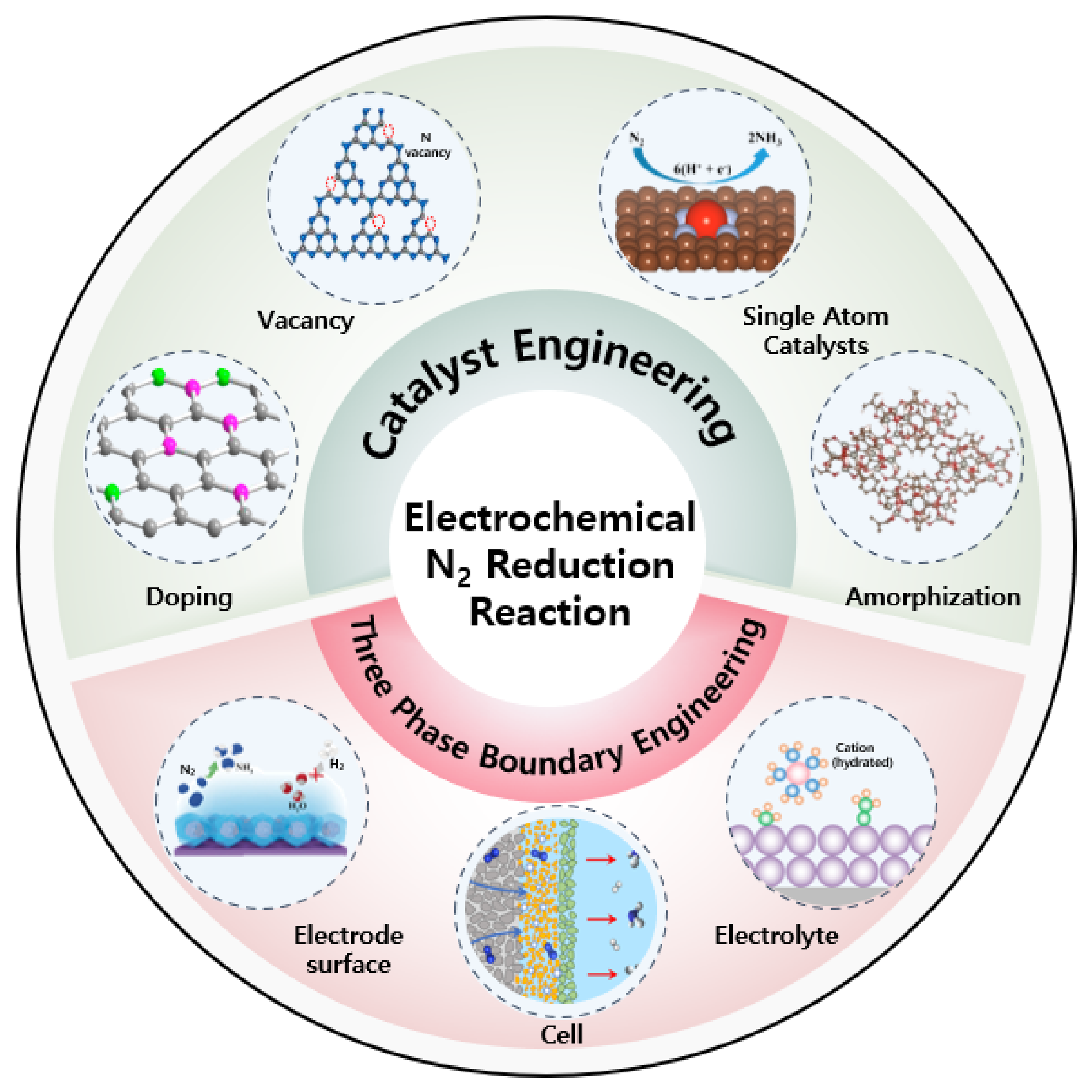
In this review, we will first discuss the essential ENRR thermodynamics fundamentals, kinetics related to reaction mechanisms, and other factors affecting the ENRR’s performance. Next, we review the widely studied catalyst design strategies and reaction environmental engineering. Moreover, we will thoroughly investigate each strategy’s effect on the ENRR’s performance (Scheme 1). Finally, we end this review by showing ENRR’s great prospects and the direction for further investigation to apply it in the future.
2. The Fundamentals
The ENRR is composed of multiple steps of proton-coupled electron transfers involving six protons and six electrons. The ENRR’s half-reactions in acidic (1) and basic solutions (2) with standard reduction potential against reversible hydrogen evolution (RHE) reaction are given, respectively [14]
N2(g) + 6H+(aq) + 6e− ⇌ 2NH3(aq) (E0 = 0.092 VRHE)
N2(g) + 6H2O(l) + 6e− ⇌ 2NH3 + 6OH−(aq) (E0 = 0.092 VRHE)
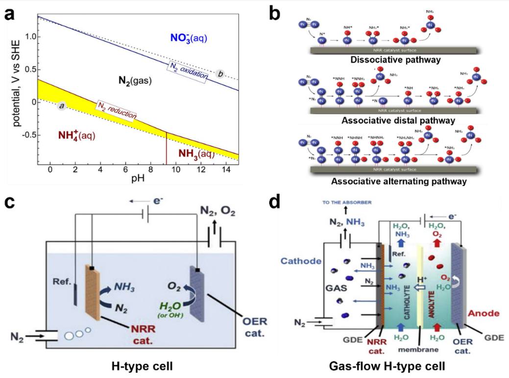
The Pourbaix diagram for N2-H2O in Figure 1a represents thermodynamically favored species and phases depending on potential and the solution’s pH [3]. Thermodynamically, only the ENRR is available and thus FE for NH3 must be 100% at the potential and pH within the yellow-colored area. This area is between the red solid line representing N2 reduction to NH4+ or NH3 and the line ⓐ representing the hydrogen evolution’s reaction (HER, 2H+(aq) + 2e− ⇌ H2(aq), E0 = 0.000 VRHE). Furthermore, ENRR can be more favorable than HER at the potential below 0 VRHE. However, the ENRR’s performance is very poor in the yellow-colored area and the HER is more favorable than the ENRR at the potential below 0 VRHE. The experimental observation can be supported by an additional challenge for the kinetic manner.
As shown in Figure 1b, pathways for N2 to NH3 conversion using six transferred electron and proton pairs are mainly represented as dissociative or associative steps [21]. In the dissociative pathway, the dissociated N atom is strongly adsorbed to the catalyst surface by the perfect cleavage of triple bonds from the N2 molecule. Then, NH3 is produced by multiple hydrogenations. However, this dissociative process is much more relatable to the NH3 production via the Haber–Bosch process performed under high temperature and pressure than the ENRR because the N2 triple bonds cleavage requires enormous energy input. Meanwhile, the ENRR’s mechanism is well-followed by the associative pathway where the first hydrogenation occurs with the adsorbed N2 (*N2), forming an *N2H intermediate [23]. The associative mechanism is further classified into two different pathways: the distal and alternating pathways. In the distal associative pathway, the N atom that is far from the catalyst’s adsorption site is first hydrogenated with the three transferred electrons and protons and then released as NH3. The other N atom still adsorbed on the catalyst conducts further hydrogenation to form NH3. On the other hand, in the alternating pathway, the protons are alternately bonded with both N atoms until the final N-N bond is cleaved [14]. Finally, two NH3 molecules are released. The initial step of N2 adsorption and activation by forming the *N2H intermediate is a serious rate-determining step among the multiple steps for the ENRR. Furthermore, this multi-proton-coupled electron transfer process involves diverse intermediate formations, such as *NNH, *NH2, and *NHNH with severe complexity. This results in sluggish kinetics relative to the HER, requiring a simple electron transfer with protons. Combining the thermodynamic and kinetic manner for the ENRR, a rational design of catalysts is critical for facilitating N2 adsorption, activation, and selective NH3 production with multiple byproduct evolution or competitive HER suppression.
The ENRR’s performance is evaluated mainly using two factors of FE that represent the utilization ratio of the passed coulomb in NH3 production and the production rate that shows the amount of NH3 produced using a unit area (1 cm2) of electrodes during an hour. The US Department of Energy (DOE) aims to achieve an FE of 50% for the ENRR and an NH3 production rate of over 1700 μg h—1 cm—2 [24]. However, the FE and production rate typically trade off in most reports [25,26]. Therefore, the suitable three-phase boundary of N2(g)-catalyst(s)-H2O(l) with well-controlled mass transport of reactants and products, including catalyst engineering, is required to finally advance the NH3 production rate [27]. The majority of ENRR has been performed in typical H-type cells, where the two compartments were separated with a membrane with a N2 purging electrolyte as shown in Figure 1c [22,28,29]. However, since the N2 gas solubility in H2O is significantly low, reaching as low as 0.0126 mg·g−1, the effective three-phase boundary representing active sites is insufficient, resulting in a low ENRR performance [20]. Thus, a strategy of adjusting the N2 and H2O concentrations in catalysts needs to be suggested. For example, a proposed representative is promoting the N2 concentration near the catalyst by directly supplying N2 gas across a gas diffusion electrode (GDE) as shown in Figure 1d [22]. Like this strategy, diverse reaction environmental engineering is required to enhance performances. Considering the discussed ENRR fundamentals, the strategies to design catalysts and systems and their effect on the ENRR’s performance will be reviewed in the next section.
3. Catalyst Engineering
Electrocatalysts for the ENRR have been developed using metals (Ag, Cu, W, Mo, Se, Fe, etc.), non-metals (Cl, B, F, P, S, O, N, etc.), metal oxides (TiO2, Bi4V2O11, etc.), metal sulfide (MoS2), and carbon-based materials (graphdiyne, g-C3N4, N-doped carbon, etc.). In this section, we will review the representative strategies for ENRR improvement via facilitating N2 activation and suppressing the competitive reaction.
3.1. Doping
Doping with atoms of different sizes and charge to the original electrocatalyst has been widely suggested in various electrocatalytic applications. The dopants can alter the electrocatalyst’s electronic structure and change the binding strength of the reactant, intermediate, or product at active sites. Thus, they govern the electrocatalytic performance [30,31,32,33].
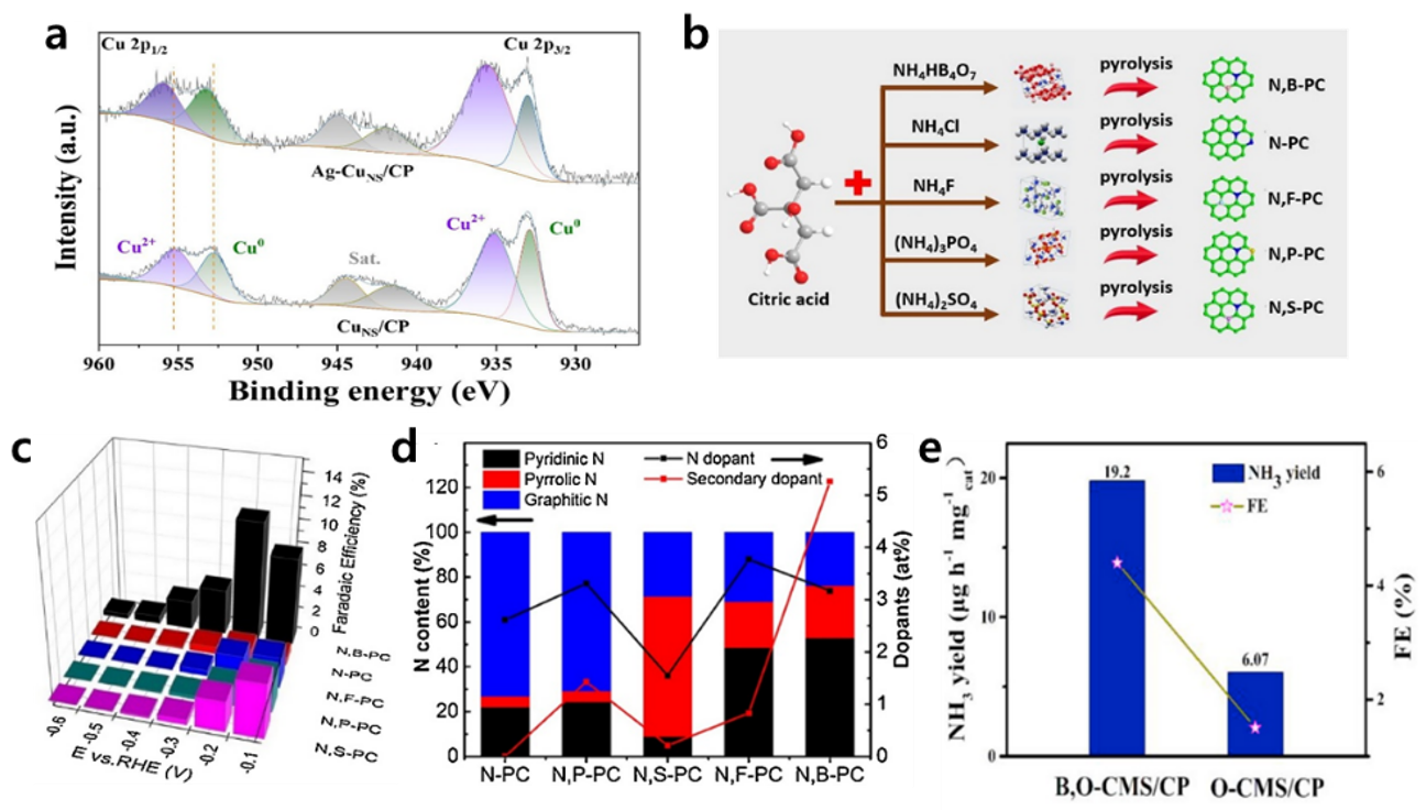
Recently, Qing Jiang et al. prepared Ag-doped Cu nanosheets cultivated on carbon paper (Ag-Cuns/CP) by a simple electrochemical deposition [34]. The prepared Ag-Cuns/CP exhibited a highly advanced ENRR compared to undoped Cuns/CP. For example, at −0.4 VRHE in 0.1 M of Na2SO4, the Ag-Cuns/CP catalyst showed an FE of 20.9% and an NH3 production rate of 4.56 μg h−1 cm−2, whereas Cuns/CP showed an FE of only 3.14% and an NH3 yield rate of 2.28 μg h−1 cm−2. As revealed by X-ray photoelectron spectroscopy (XPS) on the Ag-doped Cu nanosheets sample, as shown in Figure 2a, the binding energy of Cu0 positively shifted compared to the pristine Cu nanosheets and that of Ag0 was negatively shifted compared to bulk Ag particles. This indicates that electrons from Cu sheets were partially transferred into Ag dopants, resulting in the formation of electron-deficient Cu sites in Ag-Cuns/CP. The electron-deficient Cu sites prevent proton adsorption and simultaneously provide opportunities to accept lone-pair electrons of N2 molecules due to the suitable overlapping of orbitals from N2 and electron-deficient Cu. Consequently, the properties induced by Ag doping on the Cu nanosheets suppress the HER and facilitate ENRR.
Carbon-based metal-free catalysts have been receiving great attention due to their attractive properties, such as high surface area, excellent conductivity, easily controllable defects, and effective cost [35]. To utilize these characteristics, Lele Duan et al. suggested metal-free Cl-doped ultrathin graphdiyne (Cl-GDY) electrocatalysts prepared by annealing the pristine GDY precursors with Ar and Cl2 gases [36]. At −0.45 VRHE in 0.1 M HCl, the prepared Cl-GDY exhibited an FE of 8.7% and an NH3 production rate of 10.7 μg h−1 cm−2, whereas pristine GDY exhibited an FE of 2.5% and a NH3 production rate of 3.02 μg h−1 cm−2. Investigating the intensity ratio of the D to G band (ID/IG), representing the defect density and induced structural disordering of the carbon materials in Raman spectra revealed that the Cl-GDY exhibited a highly enhanced ratio compared with the pristine GDY. This implies that the Cl dopants increase defect sites, acting as active sites and structural distortions of GDY, resulting in improved ENRR performance.
Furthermore, the synergistic effect of dual heteroatom doping for ENRR was reported using citric acid-derived carbon electrocatalysts. Zhong-Yong Yuan et al. prepared dual heteroatom doped porous carbon (PC) by combining N dopants with B, F, P, or S dopants as shown in Figure 2b [37]. Depending on the dopant’s combination, their FEs were altered significantly as shown in Figure 2c. Among them, N, B-doped porous carbon (N,B-PC) exhibited the highest FE of 10.58% and an NH3 production rate of 16.4 μg h−1 cm−2 at −0.2 VRHE in 0.1 M HCl. The major contribution of dual dopants was investigated using Raman spectroscopy. Considering the (ID/IG), all dual-doped PCs, N,B-PC (1.025), N,F-PC (1.006), N,P-PC (0.978), and N,S-PC (0.976) demonstrated an increased structural disordering compared with the single N doped PC (0.962). Furthermore, N and B dual doping, pyridinic N ratio, and providing active sites for strong adsorption for N2 largely increased compared to others in the XPS N 1s spectra (Figure 2d). Those two results indicate that dual heteroatom doping can effectively control the disordering and electronic structure of electrocatalysts affecting N2 activation on active sites, resulting in ENRR improvement.
Dunmin Lin et al. also prepared dual-doped electrocatalysts, B,O-co-doped carbon microspheres (B,O-CMS) via a hydrothermal method [15]. The prepared B,O-CMS achieved a two-fold enhanced FE of 5.57% and an almost triple NH3 production rate of 1.92 μg h−1 cm−2 compared with O-CMS at −0.25 VRHE in 0.1 M HCl as shown in Figure 2e. The B,O-CMS showed an increased ID/IG ratio of 0.93 compared to the single doped O-CMS (0.88) in Raman spectra, indicating that the B,O-CMS has more defect sites acting as active sites than the O-CMS. Furthermore, as revealed by the Brunauer–Emmett–Teller (BET) measurements, the B,O-CMS provided more surface area than the O-CMS, in which each B,O-CMS and O-CMS showed a surface area of 488.7 and 373.6 m2 g−1, respectively.
These reports demonstrated that the doping strategy can adjust key factors for the ENRR by developing defect sites, providing or inducing neighbor’s active sites, ordering/disordering the shift, surface area, and so on.
3.2. Vacancy
Surface vacancy formation is one of the most used strategies for creating active sites for ENRR. Vacant sites can have abundant localized electrons to preserve charge neutrality. The enriched electrons can weaken the N2 triple bond, resulting in facilitating the ENRR [38]. In this part, we will thoroughly review the progress on oxygen (Ov), nitrogen (Nv), and sulfur vacancies (Sv) derived from various electrocatalysts (TiO2, C3N4, W2N3, and MoS2).
The Ov formation has been the most developed strategy for ENRR, particularly for metal oxide-based electrocatalysts. Zhenyu sun et al. prepared Ov rich TiO2 via a solvothermal method and then annealed at different temperatures of 700, 800, and 900 °C under Ar gas flow [39]. At −0.12 VRHE in 0.1 M HCl, the Ov rich TiO2 sample annealed at 800 °C achieved the highest FE of 6.5% and an NH3 production rate of 3.6 μg h−1 cm−2 among others. For example, the pristine TiO2 showed a low FE and NH3 production rate (2.4% and 1.5 μg h−1 cm−2, respectively). They conducted O 1s XPS measurements to investigate atomic compositions and their chemical states on the catalyst’s surface. Each Ov rich TiO2 sample, annealed at 700, 800, and 900 °C, was composed of Ov 18.4, 32.2, and 25.6%, respectively. Furthermore, the electron localized near the Ov sites managed to partially reduce the oxidation state of Ti4+, which served as an active site for ENRR. As the annealing temperature increased from 700 to 800 °C, the Ov amount also increased. However, when the annealing temperature increased from 800 to 900 °C, the Ov amount decreased. This was mainly due to the unintentional crystal structure’s change from original anatase to rutile over 800 °C. Ov formation is much more favored in the anatase phase relative to rutile [40]. As expected, the amount of reduced Ti4+ increased from 700 to 800 °C, but decreased from 800 to 900 °C in Ti 2p XPS. Those results reveal that reduced Ti4+ sites coupled with Ov were critical for the ENRR.
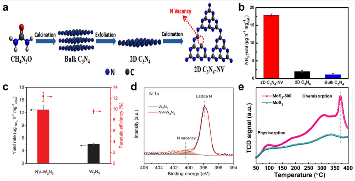
Jiantai Ma et al. prepared an N2 vacant 2D C3N4 (2D C3N4-NV), showing good stability and a large specific surface area via annealing 2D C3N4 nanosheets at 600 °C under an N2 gas flow for 15 min as shown in Figure 3a [41]. The prepared 2D C3N4-NV exhibited a highly advanced FE of 10.96% and an NH3 production rate of 178.5 μg h−1 cm−2 at −0.30 VRHE in 0.1 M HCl compared with pristine 2D C3N4 in Figure 3b. The dramatic performance advances by Nv formation were mainly due to the N2 adsorption ability, which is regarded as the primary challenge for ENRR. Based on the N2 adsorption–desorption isotherm measurements, the N2 adsorption capacity of 2D C3N4-NV was 193.6 cm3 g−1, which is almost 2 times and 1.4 times better than that of bulk C3N4 (91.5 cm3 g−1) and 2D C3N4, respectively. Furthermore, density functional theory (DFT) calculations support that electron-rich Nv sites can facilitate N2 adsorption via weakening the N2 triple bonds, resulting in a superior ENRR performance for 2D C3N4-NV.
Shi-zhang Qiao et al. prepared Nv on 2D layered W2N3 with excellent structural stability (NV-W2N3) by annealing Na2W4O13 under an NH3 gas flow [42]. The presence of Nv sites on W2N3 was revealed via XPS N 1s spectra, where N vacancy peaks at 400.2 eV could be observed in Figure 3c. Furthermore, in the extended X-ray absorption fine structure (EXAFS), NV-W2N3 showed a weakened W-N bonding, indicating a decreased W-N bonding number compared to pristine W2N3 in Figure 3d. The pristine W2N3 showed an FE of 3.5% and an NH3 production rate of 0.94 μg h−1 cm−2 at −0.2 VRHE in 0.1 M KOH. The ENRR performance was significantly improved by Nv formation, showing an FE of 11.67% and NH3 production rate of 2.332 μg h−1 cm−2 at the same experimental condition as shown in Figure 3e. From the DFT calculation, it is revealed that electron-deficient W in W2N3 induced by Nv facilitates N2 adsorption and lowers the thermodynamic limiting potential of ENRR.
Recently, strategies for inducing sulfur vacancies (Sv) have been widely proposed, such as Ov and Nv formation. The molybdenum disulfide (MoS2), which is a representative electrocatalyst of HER, has been proposed as a catalyst for ENRR by Sv engineering [43,44]. Deliang Chen et al. developed Sv-rich MoS2 by molybdenite precursors annealing at 800 °C (MoS2-800) in an Ar gas flow [45]. As a result, the prepared MoS2-Sv achieved an FE of 17.9% and an NH3 production rate of 9.352 μg h−1 cm−2 at −0.35 VRHE in 0.1 M HCl, showing twice and 3.5-times higher FE and NH3 production rate for pristine MoS2, respectively. The major contribution of Sv was revealed in the XPS spectra of Mo 3d, where the peak attributed to Mo4+ was positively shifted for MoS2-800 compared with pristine MoS2. On the other hand, in the XPS spectra of S 2p, the peaks attributing to S2- were negatively shifted for MoS2-800 relative to MoS2. The peak shift of Mo implies electron transferring from Mo to other defect sites, whereas the peak shift of S implies the existence of deficient electrons. Additionally, the N2 temperature-programmed desorption (N2-TPD) results clearly exhibit the critical effect of Sv as shown in Figure 3e. The MoS2-800 represents a much stronger N2 physisorption peak at 98 °C and chemisorption peak at 385 °C compared to the pristine MoS2, indicating that Sv in MoS2-800 enhanced the N2 adsorption ability. The progresses discussed in this part shows that vacancy engineering can effectively alter oxidation states around vacancies, affecting N2 adsorption by weakening the N2 triple bonds and increasing N2 adsorption capacities, consequently enhancing ENRR.
3.3. Single Atom Catalysts
Single atom catalyst (SAC) synthesis has been regarded as a promising technique for catalyst development. The prepared SACs show outstanding catalytic performances with an extremely high number of active sites and unique electronic properties affecting catalytic pathways [17]. Metal SACs—such as Au, Cu, Fe, and so on—have been proposed and exhibited excellent ENRR performances.
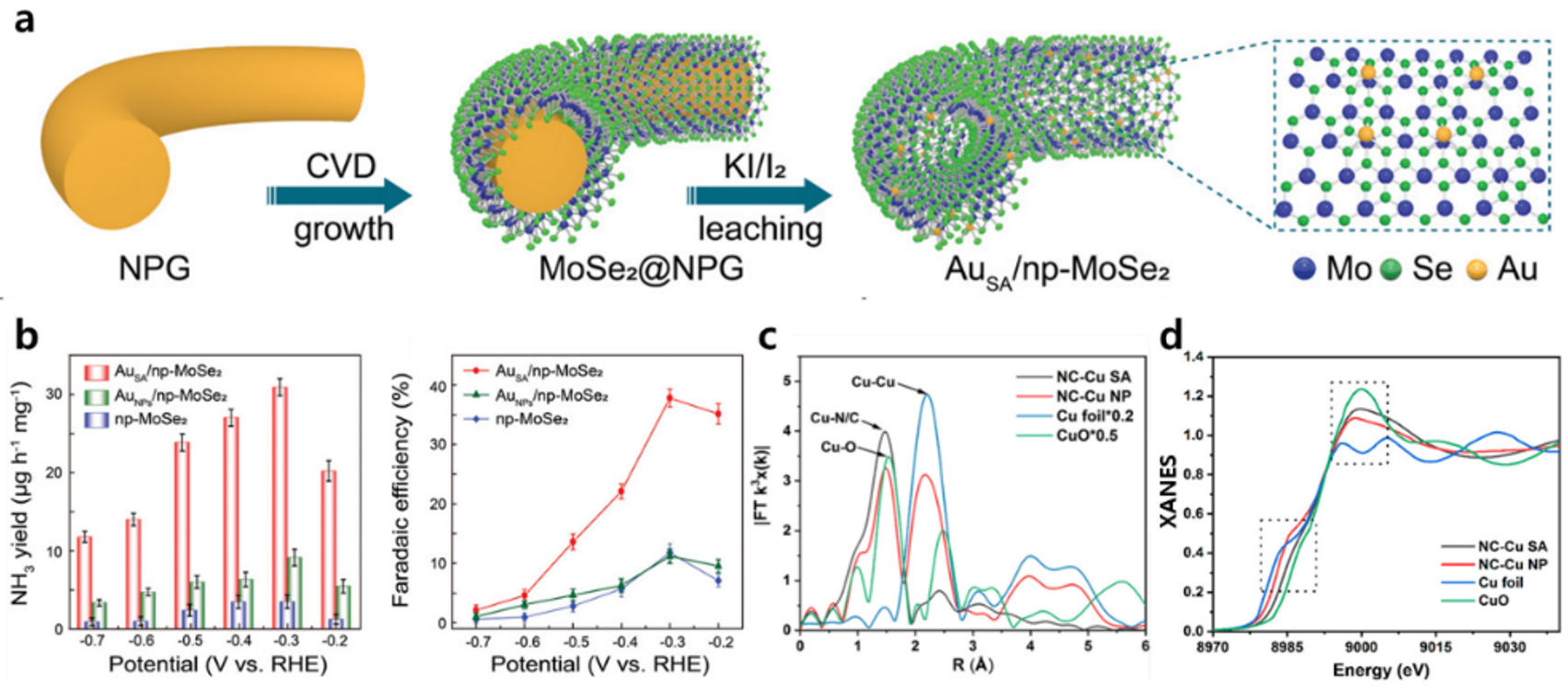
Yongwen Tan et al. prepared Au SACs on nanoporous MoSe2 (AuSA/np-MoSe2) by chemical vapor deposition followed by chemical etching [46]. They compared their ENRR performances with Au nanoparticles on np-MoSe2 (AuNPs/np-MoSe2) and np-MoSe2 alone as shown in Figure 4a,b. At −0.3 VRHE in 0.1 M Na2SO4, the AuSA/np-MoSe2 catalyst achieved an FE of 37.82% and an NH3 production rate of 6.166 μg h−1 cm−2, whereas AuNPs/np-MoSe2 and np-MoSe2 exhibited an FE and NH3 production rate of 11.06% and 1.818 μg h−1 cm−2 and 11.78% and 0.69 μg h−1 cm−2, respectively. Since the Mo dichalcogenides including MoSe2 provide excellent catalytic sites for HER [47], ENRR’s representative competitive reaction, the major contribution for NH3 production enhancement was expected for Au particles. From the XPS spectra of Au 4f, AuSA/np-MoSe2 showed a positively shifted peak attributed to Au0 compared with AuNPs/np-MoSe2. This indicates that the Au single atom becomes electron-deficient due to a stronger electronic interaction between AuSA and MoSe2, unlike the interaction between AuNPs and MoSe2. Furthermore, Gibbs-free energies calculations for N2 adsorption on Au additionally supported that the electron-deficient isolated Au single atoms on MoSe2 efficiently inhibited the HER and facilitated N2 adsorption with the following hydrogenation.
Stephen J. Pennycook et al. synthesized Cu single atoms in porous N-doped carbon (NC-Cu SA) using a surfactant-assisted method [48]. As shown in Figure 4c, the presence of a single Cu atom was revealed by EXAFS for Cu K-edge. The NC-Cu SA represents the Cu-N/C peak with a negligible Cu-Cu peak, while NC-Cu NP shows only the Cu-Cu peaks representing the Cu nanoparticle. Furthermore, the single Cu atom in NC-Cu SA represents a positively charged valence state close to Cu2+, unlike Cu particles representing a metallic Cu0 state in NC-Cu NP as shown in Figure 4d. The electron-deficient Cu single atoms can provide strong N2 adsorption sites as the first step for the ENRR. The NC-Cu SA catalyst exhibited relatively excellent performance with an FE of 13.8% and an NH3 production rate of 53.3 μg h−1 cm−2 at −0.35 VRHE in 0.1 M KOH, whereas NC-Cu NP exhibited an FE of only 4.7% and an NH3 production rate of 26.8 μg h−1 cm−2.
Naturally, NH3 can be produced by the biological N2 fixation over nitrogenase enzyme comprising Fe metal with ligands [49]. Xijun Liu et al. synthesized a Fe single atom on N-doped carbon frameworks (FeSA-NC) inspired by the nitrogenase using the hydrothermal method followed by carbonization [50]. The FeSA-NC exhibited an FE of 18.6% and an NH3 production rate of 62.9 μg h−1 cm−2 at −0.4 VRHE in 0.1 M phosphate buffer solution. The ENRR performance of FeSA-NC was highly advanced compared to that of FeNPs-NC. The presence of single Fe atoms on NC was revealed by EXAFS, where the Fe-N bond was shown with a negligible Fe-Fe bond, representing the Fe atom’s coordination with the nitrogen atoms but not between the Fe atoms. This result indicates that the Fe-N sites provide an active site for N2 adsorption and that Fe single atoms contribute to weakening the triple-bond length of N2 from 1.098 to 1.134 Å.
This subsection demonstrated that SACs have various properties compared to nanoparticle catalysts. For example, SACs change their oxidation state or those of surrounding materials, effectively adsorbing N2 and weakening the triple bond, consequently enhancing the ENRR.
3.4. Amorphization
Surface amorphization is a promising catalyst engineering technique that partially or completely reduces the crystallinity of regular crystal structures on the catalyst’s surface. Compared to highly crystalline structured catalysts, catalysts with reduced crystallinity or an amorphous surface nature can form a lot of defect sites comprising uncoordinated dangling bonds. Furthermore, they can provide lots of sites for reactant adsorption, which is typically the first sluggish step for catalytic reactions [51,52,53].
Qing jiang et al. prepared amorphous Au NPs on CeOx-reduced graphite oxide (a-Au/CeOx-RGO) using the co-reduction method [54]. The CeOx can reduce the crystallinity of Au and amorphized it. The RGO can provide substrates dispersing the Au NPs. The a-Au/CeOx-RGO achieved an FE of 10.1% and an NH3 production rate of 1.66 μg h−1 cm−2 at −0.2 VRHE in 0.1 M HCl, whereas crystalline Au/RGO only exhibited an FE of 3.67% and a NH3 production rate of 0.7 μg h−1 cm−2. In Au 4f XPS spectra, Au in both a-Au/CeOx-RGO and c-Au/RGO shows a metallic state. However, in X-ray diffraction (XRD) patterns, unlike c-Au/RGO, a-Au/CeOx-RGO shows no Au crystalline peak, indicating the amorphous state of Au/CeOx-RGO. Thus, a-Au/CeOx-RGO improves ENRR because its amorphous state has an abundance of unsaturated active sites.
Guihua Yu et al. prepared both amorphous and crystalline Bi4V2O11/CeO2 using electrospinning with a precursor solution containing different Ce:Bi ratios (1:2 for amorphous and 1:4 for crystalline) and followed calcination [55]. Since the CeO2 adjusts heat transfer, affecting the neighbor metal’s oxidation during calcination, the Ce:Bi ratio can control the crystallinity of Bi4V2O11. The amorphous Bi4V2O11/CeO2 produces an FE of 10.16% and an NH3 production rate of 46.42 μg h−1 cm−2 at −0.2 VRHE in 0.1 M HCl, which is about three-times higher FE and a 2.8-fold higher NH3 production rate for crystalline Bi4V2O11/CeO2. The crystalline Bi4V2O11/CeO2 showed Bi4V2O11 of orthorhombic type and CeO2 cubic type in the XRD pattern, whereas amorphous Bi4V2O11/CeO2 showed no obvious Bi4V2O11 peak. Interestingly, unlike the crystalline Bi4V2O11/CeO2 showing only Bi3+ and V5+, and dominant lattice O peaks in XPS spectra for Bi 4f, V 2p, and O 1s, respectively, the amorphous Bi4V2O11/CeO2 shows Bi3+ and Bi5+, V5+ and V4+, and an abundance of oxygen vacancy peaks. The additional Bi5+ and V4+ peaks with oxygen vacancies are observed only for the amorphous sample. This indicates that the amorphous Bi4V2O11/CeO2 have intrinsically localized electrons around the defect sites derived from amorphization. Furthermore, they can activate the N2 adsorption and the first hydrogenation step using a transferred electron and proton.
Ke Chu et al. suggested amorphous FeB2 nanosheets prepared by a facile reflux method as an electrocatalyst for ENRR [56]. This amorphous FeB2 exhibited an FE of 16.7% at −0.2 VRHE and an NH3 production rate of 7.96 μg h−1 cm−2 at −0.3 VRHE in 0.5 M LiClO4, which are 2- and 3-times higher FE and production rates for crystalline FeB2, respectively. This catalytic enhancement’s major contribution was revealed by electrochemical active surface area (ECSA) measurements. The amorphous FeB2 exhibited 1.56-times higher ECSA than crystalline FeB2, indicating that amorphous FeB2 has a large active surface area than the crystalline one. Additionally, considering the results of N2 TPD, the amorphous FeB2 showed a stronger chemical desorption peak than crystalline FeB2, implying an enhanced N2 adsorption ability of amorphous FeB2 due to the increase in uncoordinated and defective sites in amorphous FeB2.
These studies support the idea that amorphization is a suitable strategy for increasing the active surface area, number of active sites, effectively providing the appropriate N2 adsorption strength.
The performance for ENRR depending on strategies for catalyst modification are summarized in Table 1.
4. Three-Phase Boundary Engineering
The formation of the three-phase boundary (TPB) of N2(g)-catalyst(s)-H2O(l) is critical for the actual ENRR [27,72]. The advanced TPB can effectively suppress HER, the representative competitive reaction, and develop the NH3 production rate. In this section, strategies for engineering TPB from electrode surface modification to systematic reaction environmental engineering will be discussed in detail.
4.1. Electrode Surface Modification
In typical aqueous ENRR systems, the low N2 solubility (0.0126 mg·g−1) prevents the effective transfer of N2, unlike the free accessibility of H2O, causing a significantly lower N2 concentration near catalysts than H2O [20]. It provides an insufficient TPB condition, resulting in an ineffective FE and production rate for ENRR.
One strategy to advance the TPB is modifying the electrode’s surface which has a partial hydrophobic nature. Xing Yi Ling et al. suggested coating over the Ag-Au catalyst with the hydrophobic zeolitic imidazolate framework-71 (ZIF-71) (Ag-Au@ZIF-71) by a wet chemical deposition [73]. The distinct characteristics of ZIF-71, having a unique pore structure comprising metal centers and hydrophobic functional groups of dichloroimidazole linkers provides a superhydrophobic barrier, effectively suppressing the free access of H2O to catalysts [74]. Furthermore, the N2 molecules can freely diffuse through the ZIF-71 layer and thus be concentrated near the catalyst surface. The relatively reduced H2O concentration and increased N2 concentration on catalysts by surface modification with ZIF-71 develop the TPB, effectively resulting in an enhanced ENRR. Ag-Au@ZIF-71 electrode exhibited an advanced FE of 18 ± 4% and an NH3 production rate of ~0.648 μg h−1 cm−2 at −2.9 VAg/AgCl in the solution of 0.2 M LiCF3SO3 added to ethanol containing dry tetrahydrofuran (TPB), whereas the uncoated Ag-Au electrode showed an FE of only 9% and an NH3 production rate of 0.1296 μg h−1 cm−2. Furthermore, continuous local N2 saturation led to long-term stability with improved accessibility of N2 to the catalyst’s surface by ZIF-71. The Ag-Au@ZIF-71 represented constant CV features during 45 consecutive potential sweeps between −3 and −0.5 VAg/AgCl. On the other hand, the Ag-Au catalyst showed that the shape of CV was continuously deformed during the consecutive experiments, gradually flattening.
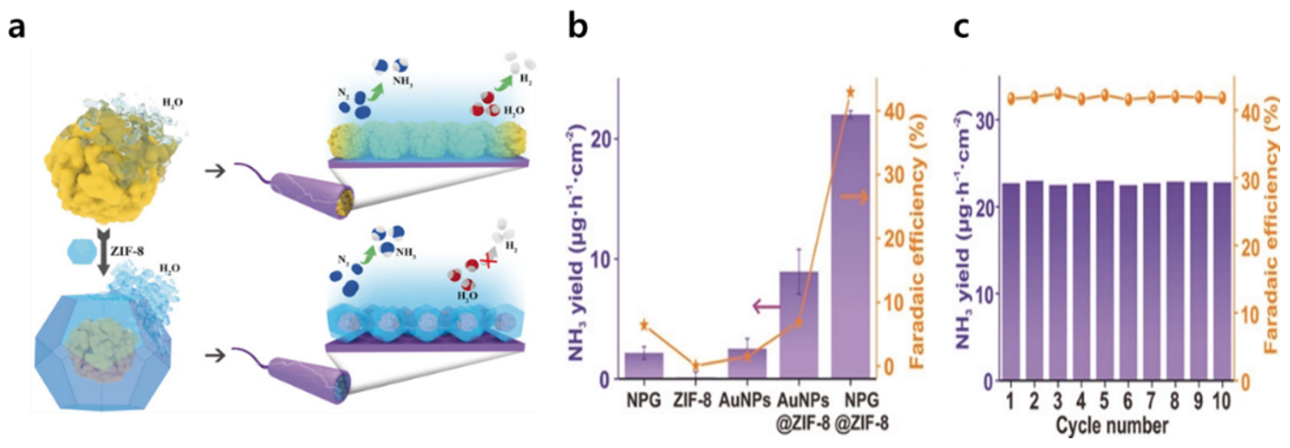
Miao Du et al. proposed a core–shell nanoporous gold (NPG) by encapsulating NPG with ZIF-8 (NPG@ZIF8) as shown in Figure 5a [19]. The 2-methylimidazole linkers comprising ZIF-8 provided a hydrophobic nature and suppressed H2O accessibility toward NPG catalysts [74]. As shown in Figure 5b, NPG@ZIF-8 showed an FE of 44% and an NH3 production rate of 22.0 ± 0.3 μg h−1 cm−2 at −0.6 VRHE in 0.1 M Na2SO4, which is 7 times and a 10-fold higher FE and production rate than NPG alone, respectively. The improved ENRR performance mainly originated from ZIF-8 encapsulating NPG by effectively suppressing the competitive HER. NPG@ZIF-8 showed stability with very little change in FE and NH3 production rate even after 10 consecutive experiments for 2 h each as shown in Figure 5c.
Even for photoelectrochemical applications, TPB engineering is important for producing NH3 using N2 and H2O with generated photoexcited electrons. Shuangyin Wang et al. proposed a surface modification of a Si-based photocathode using a hydrophobic PTFE porous framework [75]. The photo-excited electrons generated by light absorption from Si were transferred to Au nanoparticles (Au NP), serving as active sites for ENRR. Since PTFE on Si photocathodes provides a hydrophobic environment originating from strong C-F bonds and resulting in low F polarization and low van der Waals force, H2O access was dramatically suppressed with accelerating N2 diffusion toward Au NPs. As a result, the PTFE modified Si photocathode exhibited an FE of 37.8% and an NH3 production rate 18.9 μg h−1 cm−2 at −0.2 VRHE in 0.05 M H2SO4 with 0.05 M Na2SO3 under 1 sun illumination. Its performance was 4- and 1.5-times higher than FE and production rate for pristine Si photocathode with Au NP, respectively.
Furthermore, Pei Kang Shen et al. suggested a way for accumulating N2 molecules to increase the relative N2 concentration, resulting in superior TPB for ENRR [76]. They prepared an aerobic-hydrophilic hetero-structured electrocatalyst using ultrathin Bi5O7I nanotubes (UP-BOIN) and carbon spheres. The UP-BOIN served as the active sites and showed a highly porous surface structure with a diameter of about 5 nm with a hollow tubular geometry. This morphological trait provides a super-aerophilic nature. Then, the UP-BOIN was combined with the hydrophilic carbon sphere, modified by immersing them in H2O2 and 70 wt % H2SO4 in series. The combined aerophilic UP-BOIN and hydrophilic carbon sphere can control N2 accumulation and H2O accessibility, affecting the superior TPB formation. For example, the 75% UP-BOIN with the 25% carbon sphere sample shows an FE of 6.10% and an NH3 production rate of 2.286 μg h−1 cm−2 at −0.4 VRHE in 0.1 M Na2SO4. On the other hand, the electrode of 0% UP-BOIN with a 100% carbon sphere shows an FE and a production rate close to 0, indicating that UP-BOIN is a key electrocatalyst providing active sites. Furthermore, the sole UP-BOIN showed a significantly lower 5.19% FE and 0.796 μg h−1 cm−2 NH3 production rate compared to the carbon sphere combined UP-BOIN. This indicates that the effective control of reactant concentration, including H2O, is critical for providing a sufficient TPB for the ENRR.
4.2. Reaction Environmental Engineering
As stated in previous sections, both catalyst modification and TPB advances can play key roles in ENRR development. Thus, it is significantly critical for developing superior TPB via controlling the local concentration of N2 and H2O near catalysts. In this section, we will further discuss reaction environmental engineering strategies to develop TPB, including modification of N2 gas supply, additives in electrolytes, etc.
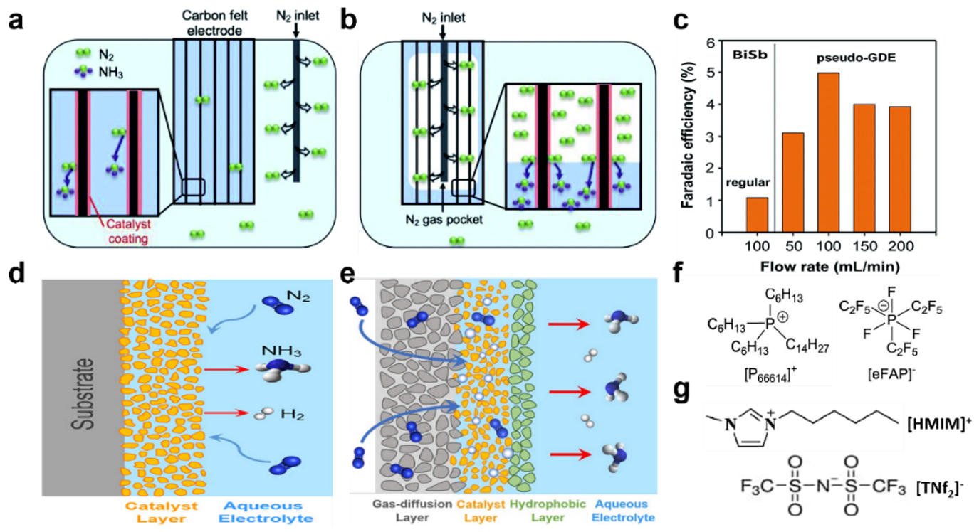
Kyoung-Shin Choi et al. revealed how local N2 and H2O concentrations influence ENRR by suggesting the simple cell modification for N2 supplying [77]. As shown in Figure 6a, a BiSb alloy-based porous electrode—named the ‘regular electrode’—was placed in the typically used setup, where ENRR was performed using dissolved N2 molecules in H2O. Additionally, a pseudo-gas diffuse electrode (pseudo-GDE) was proposed by changing the N2 purging position into the electrode instead of the electrolyte, resulting in a direct N2 gas supply near the catalyst as shown in Figure 6b. Since they compared the ENRR’s performance depending on N2 supply using perfectly consistent electrodes, the activity benefits from other possible activity-determining factors—such as electrode morphology, catalytic active sites, etc.—are negligible. As shown in Figure 6c, FEs from the pseudo-GDE were significantly altered against the N2 flow rate because it could change the air pocket’s size inside the electrode corresponding to the N2 concentration. With the increase in the N2 flow rate up to 100 mL min−1, the FEs increased, representing the N2 local concentration increase’s positive influence on the ENRR. However, over the optimum rate, the efficiencies were decreased due to the significantly limited H2O supply for catalysts, resulting in reduced TPB sites. At −0.6 VRHE, with the optimal N2 flow rate, the BiSb regular electrode showed an FE of 1.1% with an NH3 production rate of 16.29 μg h−1 cm−2 in 0.5 M borate. On the other hand, the BiSb pseudo-GDE exhibited 5% of FE, a five-fold improvement compared to the regular electrode. Furthermore, the electrode exhibited a highly advanced NH3 production rate of 66.90 μg h−1 cm−2, and the stability was shown through five experimental repetitions in which 5 C passed for each electrolysis.
Xiaofeng Feng et al. proposed a direct N2 flow cell with a GDE which followed an additional hydrophobic layer modification [20]. Unlike the typically used H-cell which severely suffers from a low concentration of N2 molecules near the catalyst due to low N2 solubility (0.0126 mg·g−1) in H2O as shown in Figure 6d, the flow cell with the gas-diffusion layer in Figure 6e can supply sufficient local N2 concentration via direct humidified N2 gas fed towards the cathode. Additionally, for the most effective TPB engineering, the developed electrode can be assembled with GDE, catalyst nanoparticles layer deposited on porous and hydrophobic carbon fiber paper, and hydrophobic layer in series as shown in Figure 6e. If the design is experimentally applied, the N2 gas directly flows and diffuses. Additionally, the protons adjusted by passing the hydrophobic layer are also transferred towards the catalyst layer, which is expected to form a suitable TPB for ENRR by effectively suppressing HER.
Another interesting way to adjust N2 concentration near catalysts is modifying the composition of electrolytes affecting N2 solubility. For example, the non-aqueous ionic liquid (IL) can intrinsically inhibit HER because of the significantly low concentration of protons. For example, N2 solubility is about 20-times higher in trihexyl(tetradecyl) phosphonium tris(pentafluoroethyl) trifluorophosphate, [P6,6,6,14][eFAP] (0.28 mg·g−1), representative IL, than the solubility in H2O (0.0126 mg·g−1) at room temperature [78]. Therefore, electrolyte engineering can give an attractive approach for controlling TPB for ENRR.
Douglas R. MacFalance et al. prepared a Fe electrocatalyst on fluorine-doped tin oxide glass (FTO) substrate by electro-deposition and ENRR was performed using the electrode in the electrolyte of [P6,6,6,14][eFAP] (Figure 6f) [81]. For comparison, ENRR was performed in another ionic liquid 1-hexyl-3-methylimidazolium bis(trifluoromethylsulfonyl)imide [HMIM][NTf2] (Figure 6g) having a relatively low solubility of 0.017 mg·g−1 than [P6,6,6,14][eFAP], showing 0.28 mg·g−1 [80]. The differing N2 solubilities in each electrolyte are due to the interaction between N2 and [eFAP]- or [NTf2]-. According to the DFT calculation, the N2 molecules can interact with [eFAP]- in two different ways: N2 binding with the C2F5 group or with F, showing a binding energy (Eb) of −0.53 and −0.42, respectively. On the other hand, N2 molecules can make bonds with CF3 groups of [NTf2]− only showing an Eb of −0.16. This indicates that [eFAP]- provides a much stronger N2 binding strength than [NTf2]-, resulting in a more favorable N2 solubility. This distinct N2 solubility difference in the two ILs proportionally affects the ENRR. The Fe electrode exhibited an FE of 60 ± 6% in [P6,6,6,14][eFAP], whereas it showed an FE of 0.64% in [HMIM][NTf2] at −0.8 VNHE.
Zhongfang Chen et al. investigated polyethylene glycol (PEG) additive’s effect in 0.05 M H2SO4 electrolyte for ENRR using TiO2 nanoarray electrodes [82]. Even if the majority of the electrolyte is H2O, a molecular crowding effect formed by hydrogen bonding between H2O and PEG can significantly suppress H2O movement. In contrast, since the N2 molecule is non-polar and its movement was not restricted by the effect, the N2 molecule can freely move in the electrolyte to reach the active site. As a result, the TiO2 electrode’s FE and NH3 production rate in the electrolyte with PEG were recorded as 32.13% and 13.6 μg h−1 cm−2 for −0.3 VRHE. On the other hand, it demonstrated an FE and production rate of only 0.8% and 5.1 μg h−1 cm−2 without PEG.
In case sufficient protons are present near the catalytic active site, H2 can be easily adsorbed on electrode surfaces before N2, leading to a poor ENRR performance. Meanwhile, local H2O accessibility and its adsorption on active electrode surfaces can be controlled by developing the fundamentals of the electrical double layer (EDL) model [83,84]. For example, if we add additional alkali metal cations to the electrolyte, their hydration is promoted in the beginning. It then suppresses H2O movement, finally reducing the local H2O concentration. Furthermore, N2 absorption strength can be enhanced via the direct adsorption of cations on the surface electrode [85].
An-Xiang Yin et al. investigated the K+ cation’s effect in acidic potassium sulfate for ENRR using Bi catalysts supported on carbon black [85]. They found FEs for ENRR from 9.8% to 66% at −0.6 VRHE depending on the concentration of the K+ from 0.2 to 1.0 M. Additionally, the NH3 production rate increased from about 230 to 884 μg h−1 cm−2. With the increase in K+ concentration, the amount of hydrated cations increases. Thus, they can be concentrated in the diffusion layer near the surface at a low potential. The advanced performance is mainly due to proton movement suppression by the hydrated K+ cations. Therefore, N2 is first adsorbed to the electrocatalyst’s surface and activated. Meanwhile, K+ directly adsorbed on the electrode can change the Bi electrode’s electronic structure, thereby reducing the Gibbs free energy difference for N2 activation (G*NNH). Thus, by adding the K+ cation in electrolytes, direct proton adsorption was effectively suppressed and N2 adsorption and activation was facilitated.
The performances for ENRR depending on strategies for environmental engineering are summarized in Table 2.
5. Summary and Perspective
NH3 is an essential precursor for chemicals that are widely used in a variety of industries. Furthermore, it is an important sustainable fuel and media for hydrogen storage. Electrochemical N2 reduction for NH3 production (ENRR) has been considered a greatly promising process alternative to the traditional Haber–Bosch process that requires a high-energy input and which emits enormous CO2 gas. Since the ENRR is performed at an ambient temperature and pressure using N2 gas and H2O as a hydrogen resource, it is economically effective and environmentally friendly. Considering those ideal potentials, the scientific community has devoted considerable effort to advancing the performance metrics, including the FE and NH3 production rate. This review presented ENRR’s governing fundamentals, such as thermodynamics, mechanisms, and mass transport. We then introduced strategies for improving its performance.
To design robust electrocatalysts that could provide superior active sites for N2 adsorption and activation while suppressing HER, defect engineering via heteroatom doping and vacancy formation have been suggested. Furthermore, effective new types of catalysts have been proposed, such as catalysts comprising a single atom grown on a supporter or having an amorphous phase on the surface. These strategies could mainly control electronic structures promoting N2 adsorption, *N2H, the first intermediate, formation, and further hydrogenation with inhibiting proton adsorption. Meanwhile, to advance the ENRR’s performance, not only catalyst engineering but also promising TPB engineering have proved to be critical. Electrode modification with functional layers and reaction environmental modification using direct N2 gas supply, ionic liquids, and additional cations have been proposed. The desired concentration of N2 and H2O near catalysts can be suggested from the modifications, overcoming the major challenges of N2 mass transport caused by its low solubility in aqueous solutions, and relatively free H2O accessibility. Recently, the research has also been proposed to improve performance by forming a compact and uniform solid electrolyte interphase (SEI) [88]. Via multiple engineering modifications, the Bi catalysts reported the highest ENRR performance with an FE of 66% and an NH3 production rate of 884 μg h−1 cm−2 at −0.6 VRHE in acidic potassium sulfate (pH 3.5, 1.0 mol L–1 of K+).
However, although strategies discussed in this review significantly advanced the ENRR, the performance is still inadequate for the ultimate technical target of practical NH3 production; namely an FE of 50% and a NH3 production rate of at least 6120 μg h−1 cm−2 [12,13]. Therefore, a combination of strategies for catalysts and reaction engineering is necessary for developing ENRR with ultra-high performance. For example, electrochemical CO2 reductions have similar challenges to ENRR, such as the facile competitive reaction of HER, sluggish first active intermediate formation using transferred electrons and protons, limited TPB caused by imbalanced CO2, and robust H2O concentration due to low CO2 solubility [89,90,91]. However, their performance was significantly advanced, making them economically feasible by combining robust catalyst developments, environmental reactions, and environmental engineering, including system and process modification. Benchmarking the signs of progress of CO2 reduction proves that ENRR could be further improved.
To turn ENRR into a practically available pathway alternative to the Haber–Bosch process, the desired electrocatalysts, environmental conditions, and the other cell components must be sustainable for at least several months. However, those stability issues are barely investigated, even for catalysts tested only for a few hours. Electrocatalysts may decompose due to poisoning, dissolution, and deactivation of active sites [14]. Furthermore, proper reaction environmental conditions can gradually differ compared to the initial state due to varying reactant and product concentrations. Furthermore, the cell components may be decomposed due to unintentional corrosion, pressure changes, etc. Therefore, prolonged stability test periods are highly recommended because they are useful for figuring out the imperfect durability’s major origins. If the remaining challenges are successfully solved using the new frontiers suggested above, the ENRR can boost the NH3 production process, significantly reducing energy consumption and CO2 emission by replacing the traditional Haber–Bosch process.
Author Contributions
Investigation, conceptualization, and categorization by Y.H.M., N.Y.K. and S.M.K.; Writing and editing by Y.H.M. and N.Y.K.; Funding acquisition, editing, and supervision by Y.J.J. This manuscript was written through contributions of all authors. All authors have read and agreed to the published version of the manuscript.
Funding
This research was funded by the Graduate school of Post Plastic specialization of Korea Environmental Industry & Technology Institute grant funded by the Ministry of Environment of Republic of Korea, the National Research of Korea (NRF) grant (no. 2021R1F1A1063146), and the Korea Institute of Energy Technology Evaluation and Planning (KETEP) and the Ministry of Trade, Industry & Energy (MOTIE) of the Republic of Korea (no. 20202020800330).
Data Availability Statement
The datasets used and analyzed during the current study are available from the corresponding references listed.
Conflicts of Interest
The authors declare no conflict of interest.
References
- Erisman, J.W.; Sutton, M.A.; Galloway, J.; Klimont, Z.; Winiwarter, W. How a century of ammonia synthesis changed the world. Nat. Geosci. 2008, 1, 636–639. [Google Scholar] [CrossRef]
- Smil, V. Detonator of the population explosion. Nature 1999, 400, 415. [Google Scholar] [CrossRef]
- Chen, J.G.; Crooks, R.M.; Seefeldt, L.C.; Bren, K.L.; Bullock, R.M.; Darensbourg, M.Y.; Holland, P.L.; Hoffman, B.; Janik, M.J.; Jones, A.K.; et al. Beyond fossil fuel-driven nitrogen transformations. Science 2018, 360, eaar6611. [Google Scholar] [CrossRef] [PubMed]
- Bolen, W.P. Mineral Commodity Summaries 2022; US Geological Survey: Reston, VA, USA, 2022; p. 202. [Google Scholar]
- Wang, K.; Smith, D.; Zheng, Y. Electron-driven heterogeneous catalytic synthesis of ammonia: Current states and perspective. Carbon Resour. Convers. 2018, 1, 2–31. [Google Scholar] [CrossRef]
- Nagaoka, K.; Eboshi, T.; Takeishi, Y.; Tasaki, R.; Honda, K.; Imamura, K.; Sato, K. Carbon-free H2 production from ammonia triggered at room temperature with an acidic RuO2/γ-Al2O3 catalyst. Sci. Adv. 2017, 3, e1602747. [Google Scholar] [CrossRef]
- Foster, S.L.; Bakovic, S.I.P.; Duda, R.D.; Maheshwari, S.; Milton, R.D.; Minteer, S.D.; Janik, M.J.; Renner, J.N.; Greenlee, L.F. Catalysts for nitrogen reduction to ammonia. Nat. Catal. 2018, 1, 490–500. [Google Scholar] [CrossRef]
- Cui, X.; Tang, C.; Zhang, Q. A review of electrocatalytic reduction of dinitrogen to ammonia under ambient conditions. Adv. Energy Mater. 2018, 8, 1800369. [Google Scholar] [CrossRef]
- Kitano, M.; Inoue, Y.; Yamazaki, Y.; Hayashi, F.; Kanbara, S.; Matsuishi, S.; Yokoyama, T.; Kim, S.-W.; Hara, M.; Hosono, H. Ammonia synthesis using a stable electride as an electron donor and reversible hydrogen store. Nat. Chem. 2012, 4, 934–940. [Google Scholar] [CrossRef]
- MacFarlane, D.R.; Cherepanov, P.V.; Choi, J.; Suryanto, B.H.R.; Hodgetts, R.Y.; Bakker, J.M.; Ferrero Vallana, F.M.; Simonov, A.N. A Roadmap to the ammonia economy. Joule 2020, 4, 1186–1205. [Google Scholar] [CrossRef]
- Smith, C.; Hill, A.K.; Torrente-Murciano, L. Current and future role of Haber–Bosch ammonia in a carbon-free energy landscape. Energy Environ. Sci. 2020, 13, 331–344. [Google Scholar] [CrossRef]
- Kyriakou, V.; Garagounis, I.; Vasileiou, E.; Vourros, A.; Stoukides, M. Progress in the electrochemical synthesis of ammonia. Catal. Today 2017, 286, 2–13. [Google Scholar] [CrossRef]
- Zhao, X.; Hu, G.; Chen, G.-F.; Zhang, H.; Zhang, S.; Wang, H. Comprehensive understanding of the thriving ambient electrochemical nitrogen reduction reaction. Adv. Mater. 2021, 33, 2007650. [Google Scholar] [CrossRef]
- Qing, G.; Ghazfar, R.; Jackowski, S.T.; Habibzadeh, F.; Ashtiani, M.M.; Chen, C.-P.; Smith, M.R.; Hamann, T.W. Recent advances and challenges of electrocatalytic N2 reduction to ammonia. Chem. Rev. 2020, 120, 5437–5516. [Google Scholar] [CrossRef] [PubMed]
- Tang, M.; Jiang, X.; He, M.; Jiang, N.; Zheng, Q.; Lin, D. B (boron), O (oxygen) dual-doped carbon spheres as a high-efficiency electrocatalyst for nitrogen reduction. Int. J. Hydrog. Energy 2021, 46, 439–448. [Google Scholar] [CrossRef]
- Peng, G.; Wu, J.; Wang, M.; Niklas, J.; Zhou, H.; Liu, C. Nitrogen-defective polymeric carbon nitride nanolayer enabled efficient electrocatalytic nitrogen reduction with high faradaic efficiency. Nano Lett. 2020, 20, 2879–2885. [Google Scholar] [CrossRef]
- Choi, C.; Back, S.; Kim, N.-Y.; Lim, J.; Kim, Y.-H.; Jung, Y. Suppression of hydrogen evolution reaction in electrochemical N2 reduction using single-atom catalysts: A computational guideline. ACS Catal. 2018, 8, 7517–7525. [Google Scholar] [CrossRef]
- Erkartal, M.; Durandurdu, M. Pressure-induced amorphization of MOF-5: A first principles study. ChemistrySelect 2018, 3, 8056–8063. [Google Scholar] [CrossRef]
- Yang, Y.; Wang, S.-Q.; Wen, H.; Ye, T.; Chen, J.; Li, C.-P.; Du, M. Nanoporous gold embedded ZIF composite for enhanced electrochemical nitrogen fixation. Angew. Chem. Int. Ed. 2019, 58, 15362–15366. [Google Scholar] [CrossRef]
- Hu, L.; Xing, Z.; Feng, X. Understanding the electrocatalytic interface for ambient ammonia synthesis. ACS Energy Lett. 2020, 5, 430–436. [Google Scholar] [CrossRef]
- Chen, X.; Guo, Y.; Du, X.; Zeng, Y.; Chu, J.; Gong, C.; Huang, J.; Fan, C.; Wang, X.; Xiong, J. Atomic structure modification for electrochemical nitrogen reduction to ammonia. Adv. Energy Mater. 2020, 10, 1903172. [Google Scholar] [CrossRef]
- Tavella, F.; Giusi, D.; Ampelli, C. Nitrogen reduction reaction to ammonia at ambient conditions: A short review analysis of the critical factors limiting electrocatalytic performance. Curr. Opin. Green Sustain. Chem. 2022, 35, 100604. [Google Scholar] [CrossRef]
- Bhunia, K.; Sharma, S.K.; Satpathy, B.K.; Pradhan, D. Recent progress in the development of electrocatalysts for the electrochemical N2 reduction reaction. Mater. Adv. 2022, 3, 888–917. [Google Scholar] [CrossRef]
- Qiao, Z.; Johnson, D.; Djire, A. Challenges and opportunities for nitrogen reduction to ammonia on transitional metal nitrides via Mars-van Krevelen mechanism. Cell Rep. Phys. Sci. 2021, 2, 100438. [Google Scholar] [CrossRef]
- Hawtof, R.; Ghosh, S.; Guarr, E.; Xu, C.; Mohan Sankaran, R.; Renner, J.N. Catalyst-free, highly selective synthesis of ammonia from nitrogen and water by a plasma electrolytic system. Sci. Adv. 2019, 5, eaat5778. [Google Scholar] [CrossRef] [PubMed]
- Yuan, Y.; Tada, S.; Kikuchi, R. Ammonia synthesis using Fe/BZY–RuO2 catalysts and a caesium dihydrogen phosphate-based electrolyte at intermediate temperatures. Mater. Adv. 2021, 2, 793–803. [Google Scholar] [CrossRef]
- Wang, H.; Chen, Y.; Fan, R.; Chen, J.; Wang, Z.; Mao, S.; Wang, Y. Selective electrochemical reduction of nitrogen to ammonia by adjusting the three-phase interface. Research 2019, 2019, 1401209. [Google Scholar] [CrossRef]
- Lijuan, N.; Ziwen, L.; Guohua, L.; Mengxuan, L.; Xupeng, Z.; Dandan, W.; Li, A.; Dan, Q.; Xiaoming, S.; Xiayan, W.; et al. Surface hydrophobic modification enhanced catalytic performance of electrochemical nitrogen reduction reaction. Nano Res. 2022, 15, 3886–3893. [Google Scholar] [CrossRef]
- Suryanto, B.H.R.; Wang, D.; Azofra, L.M.; Harb, M.; Cavallo, L.; Jalili, R.; Mitchell, D.R.G.; Chatti, M.; MacFarlane, D.R. MoS2 polymorphic engineering enhances selectivity in the electrochemical reduction of nitrogen to ammonia. ACS Energy Lett. 2019, 4, 430–435. [Google Scholar] [CrossRef]
- Xia, L.; Wu, X.; Wang, Y.; Niu, Z.; Liu, Q.; Li, T.; Shi, X.; Asiri, A.M.; Sun, X. S-doped carbon nanospheres: An efficient electrocatalyst toward artificial N2 fixation to NH3. Small Methods 2019, 3, 1800251. [Google Scholar] [CrossRef]
- Xia, L.; Yang, J.; Wang, H.; Zhao, R.; Chen, H.; Fang, W.; Asiri, A.M.; Xie, F.; Cui, G.; Sun, X. Sulfur-doped graphene for efficient electrocatalytic N2-to-NH3 fixation. Chem. Commun. 2019, 55, 3371–3374. [Google Scholar] [CrossRef]
- Cheng, S.; Li, C.; Yu, Z.; Sun, Y.; Li, L.; Yang, J. Defective S/N co-doped carbon cloth via a one-step process for effective electroreduction of nitrogen to ammonia. RSC Adv. 2020, 10, 9814–9823. [Google Scholar] [CrossRef]
- Chu, K.; Liu, Y.-p.; Li, Y.-b.; Guo, Y.-l.; Tian, Y.; Zhang, H. Multi-functional Mo-doping in MnO2 nanoflowers toward efficient and robust electrocatalytic nitrogen fixation. Appl. Catal. B Environ. 2020, 264, 118525. [Google Scholar] [CrossRef]
- Qu, Y.; Dai, T.; Cui, Y.; Zhang, Y.; Wang, Z.; Jiang, Q. Tailoring electronic structure of copper nanosheets by silver doping toward highly efficient electrochemical reduction of nitrogen to ammonia. Chem. Eng. J. 2022, 433, 133752. [Google Scholar] [CrossRef]
- Lv, C.; Qian, Y.; Yan, C.; Ding, Y.; Liu, Y.; Chen, G.; Yu, G. Defect engineering metal-free polymeric carbon nitride electrocatalyst for effective nitrogen fixation under ambient conditions. Angew. Chem. Int. Ed. 2018, 57, 10246–10250. [Google Scholar] [CrossRef]
- Zou, H.; Rong, W.; Long, B.; Ji, Y.; Duan, L. Corrosion-induced Cl-doped ultrathin graphdiyne toward electrocatalytic nitrogen reduction at ambient conditions. ACS Catal. 2019, 9, 10649–10655. [Google Scholar] [CrossRef]
- Ren, J.-T.; Wan, C.-Y.; Pei, T.-Y.; Lv, X.-W.; Yuan, Z.-Y. Promotion of electrocatalytic nitrogen reduction reaction on N-doped porous carbon with secondary heteroatoms. Appl. Catal. B Environ. 2020, 266, 118633. [Google Scholar] [CrossRef]
- Yang, C.; Zhu, Y.; Liu, J.; Qin, Y.; Wang, H.; Liu, H.; Chen, Y.; Zhang, Z.; Hu, W. Defect engineering for electrochemical nitrogen reduction reaction to ammonia. Nano Energy 2020, 77, 105126. [Google Scholar] [CrossRef]
- Han, Z.; Choi, C.; Hong, S.; Wu, T.-S.; Soo, Y.-L.; Jung, Y.; Qiu, J.; Sun, Z. Activated TiO2 with tuned vacancy for efficient electrochemical nitrogen reduction. Appl. Catal. B Environ. 2019, 257, 117896. [Google Scholar] [CrossRef]
- Morgan, B.J.; Watson, G.W. Intrinsic n-type defect formation in TiO2: A comparison of rutile and anatase from GGA+U calculations. J. Phys. Chem. C 2010, 114, 2321–2328. [Google Scholar] [CrossRef]
- Zhao, Z.; Long, Y.; Luo, S.; Luo, Y.; Chen, M.; Ma, J. Metal-Free C3N4 with plentiful nitrogen vacancy and increased specific surface area for electrocatalytic nitrogen reduction. J. Energy Chem. 2021, 60, 546–555. [Google Scholar] [CrossRef]
- Jin, H.; Li, L.; Liu, X.; Tang, C.; Xu, W.; Chen, S.; Song, L.; Zheng, Y.; Qiao, S.-Z. Nitrogen vacancies on 2D layered W2N3: A stable and efficient active site for nitrogen reduction reaction. Adv. Mater. 2019, 31, 1902709. [Google Scholar] [CrossRef]
- Hinnemann, B.; Moses, P.G.; Bonde, J.; Jørgensen, K.P.; Nielsen, J.H.; Horch, S.; Chorkendorff, I.; Nørskov, J.K. Biomimetic hydrogen evolution: MoS2 nanoparticles as catalyst for hydrogen evolution. J. Am. Chem. Soc. 2005, 127, 5308–5309. [Google Scholar] [CrossRef] [PubMed]
- Liu, J.; Zheng, Y.; Zhu, D.; Vasileff, A.; Ling, T.; Qiao, S.-Z. Identification of pH-dependent synergy on Ru/MoS2 interface: A comparison of alkaline and acidic hydrogen evolution. Nanoscale 2017, 9, 16616–16621. [Google Scholar] [CrossRef] [PubMed]
- You, M.; Yi, S.; Hou, X.; Wang, Z.; Ji, H.; Zhang, L.; Wang, Y.; Zhang, Z.; Chen, D. High temperature induced S vacancies in natural molybdenite for robust electrocatalytic nitrogen reduction. J. Colloid Interface Sci. 2021, 599, 849–856. [Google Scholar] [CrossRef] [PubMed]
- Chen, D.; Luo, M.; Ning, S.; Lan, J.; Peng, W.; Lu, Y.-R.; Chan, T.-S.; Tan, Y. Single-atom gold isolated onto nanoporous MoSe2 for boosting electrochemical nitrogen reduction. Small 2022, 18, 2104043. [Google Scholar] [CrossRef]
- Zhou, X.; Prikryl, J.; Krbal, M.; Macak, J.M.; Schmuki, P. Molybdenum dichalcogenide nanotube arrays for hydrogen-evolution-reaction catalysis: Synergistic effects of sulfur and selenium in a core-shell tube wall. Electrochem. Commun. 2017, 82, 112–116. [Google Scholar] [CrossRef]
- Zang, W.; Yang, T.; Zou, H.; Xi, S.; Zhang, H.; Liu, X.; Kou, Z.; Du, Y.; Feng, Y.P.; Shen, L.; et al. copper single atoms anchored in porous nitrogen-doped carbon as efficient pH-universal catalysts for the nitrogen reduction reaction. ACS Catal. 2019, 9, 10166–10173. [Google Scholar] [CrossRef]
- Varghese, F.; Kabasakal, B.V.; Cotton, C.A.R.; Schumacher, J.; Rutherford, A.W.; Fantuzzi, A.; Murray, J.W. A low-potential terminal oxidase associated with the iron-only nitrogenase from the nitrogen-fixing bacterium Azotobacter vinelandii. J. Biol. Chem. 2019, 294, 9367–9376. [Google Scholar] [CrossRef] [PubMed]
- Lü, F.; Zhao, S.; Guo, R.; He, J.; Peng, X.; Bao, H.; Fu, J.; Han, L.; Qi, G.; Luo, J.; et al. Nitrogen-coordinated single Fe sites for efficient electrocatalytic N2 fixation in neutral media. Nano Energy 2019, 61, 420–427. [Google Scholar] [CrossRef]
- Hu, F.; Wang, H.; Zhang, Y.; Shen, X.; Zhang, G.; Pan, Y.; Miller, J.T.; Wang, K.; Zhu, S.; Yang, X.; et al. Designing highly efficient and long-term durable electrocatalyst for oxygen evolution by coupling B and P into amorphous porous NiFe-based material. Small 2019, 15, 1901020. [Google Scholar] [CrossRef]
- Kim, J.S.; Kim, B.; Kim, H.; Kang, K. Recent progress on multimetal oxide catalysts for the oxygen evolution reaction. Adv. Energy Mater. 2018, 8, 1702774. [Google Scholar] [CrossRef]
- Nsanzimana, J.M.V.; Peng, Y.; Xu, Y.Y.; Thia, L.; Wang, C.; Xia, B.Y.; Wang, X. An efficient and earth-abundant oxygen-evolving electrocatalyst based on amorphous metal borides. Adv. Energy Mater. 2018, 8, 1701475. [Google Scholar] [CrossRef]
- Li, S.-J.; Bao, D.; Shi, M.-M.; Wulan, B.-R.; Yan, J.-M.; Jiang, Q. Amorphizing of Au nanoparticles by CeOx–RGO hybrid support towards highly efficient electrocatalyst for N2 reduction under ambient conditions. Adv. Mater. 2017, 29, 1700001. [Google Scholar] [CrossRef]
- Lv, C.; Yan, C.; Chen, G.; Ding, Y.; Sun, J.; Zhou, Y.; Yu, G. An amorphous noble-metal-free electrocatalyst that enables nitrogen fixation under ambient conditions. Angew. Chem. Int. Ed. 2018, 57, 6073–6076. [Google Scholar] [CrossRef]
- Chu, K.; Gu, W.; Li, Q.; Liu, Y.; Tian, Y.; Liu, W. Amorphization activated FeB2 porous nanosheets enable efficient electrocatalytic N2 fixation. J. Energy Chem. 2021, 53, 82–89. [Google Scholar] [CrossRef]
- Gao, Y.; Han, Z.; Hong, S.; Wu, T.; Li, X.; Qiu, J.; Sun, Z. ZIF-67-derived cobalt/nitrogen-doped carbon composites for efficient electrocatalytic N2 reduction. ACS Appl. Energy Mater. 2019, 2, 6071–6077. [Google Scholar] [CrossRef]
- Liu, X.; Jang, H.; Li, P.; Wang, J.; Qin, Q.; Kim, M.G.; Li, G.; Cho, J. Antimony-based composites loaded on phosphorus-doped carbon for boosting faradaic efficiency of the electrochemical nitrogen reduction reaction. Angew. Chem. Int. Ed. 2019, 58, 13329–13334. [Google Scholar] [CrossRef]
- Ye, W.; Yang, Y.; Arif, M.; Yang, S.; Fang, X.; Mushtaq, M.A.; Chen, X.; Yan, D. Fe, Mo–N/C hollow porous nitrogen-doped carbon nanorods as an effective electrocatalyst for N2 reduction reaction. ACS Sustain. Chem. Eng. 2020, 8, 15946–15952. [Google Scholar] [CrossRef]
- Wang, C.; Gu, L.-L.; Qiu, S.-Y.; Gao, J.; Zhang, Y.-C.; Wang, K.-X.; Zou, J.-J.; Zuo, P.-J.; Zhu, X.-D. Modulating CoFe2O4 nanocube with oxygen vacancy and carbon wrapper towards enhanced electrocatalytic nitrogen reduction to ammonia. Appl. Catal. B Environ. 2021, 297, 120452. [Google Scholar] [CrossRef]
- Li, Y.; Liang, Y.; Li, H.; Wang, B.; You, H.; Wang, Y.; Cao, Y.; Dai, W.; Gao, F. The surface engineering of MOF-derived titanium oxide–carbon multifunctional composite catalyst for efficient electrochemical nitrogen reduction. Appl. Surf. Sci. 2021, 570, 151257. [Google Scholar] [CrossRef]
- Zhao, R.; Wang, G.; Mao, Y.; Bao, X.; Wang, Z.; Wang, P.; Liu, Y.; Zheng, Z.; Dai, Y.; Cheng, H.; et al. Li-intercalation boosted oxygen vacancies enable efficient electrochemical nitrogen reduction on ultrathin TiO2 nanosheets. Chem. Eng. J. 2022, 430, 133085. [Google Scholar] [CrossRef]
- Li, C.; Xu, R.; Ma, S.; Xie, Y.; Qu, K.; Bao, H.; Cai, W.; Yang, Z. Sulfur vacancies in ultrathin cobalt sulfide nanoflowers enable boosted electrocatalytic activity of nitrogen reduction reaction. Chem. Eng. J. 2021, 415, 129018. [Google Scholar] [CrossRef]
- Ma, C.; Zhai, N.; Liu, B.; Yan, S. Defected MoS2: An efficient electrochemical nitrogen reduction catalyst under mild conditions. Electrochim. Acta 2021, 370, 137695. [Google Scholar] [CrossRef]
- Geng, Z.; Liu, Y.; Kong, X.; Li, P.; Li, K.; Liu, Z.; Du, J.; Shu, M.; Si, R.; Zeng, J. Achieving a record-high yield rate of 120.9 for N2 electrochemical reduction over Ru single-atom catalysts. Adv. Mater. 2018, 30, 1803498. [Google Scholar] [CrossRef]
- Liu, J.; Kong, X.; Zheng, L.; Guo, X.; Liu, X.; Shui, J. Rare earth single-atom catalysts for nitrogen and carbon dioxide reduction. ACS Nano 2020, 14, 1093–1101. [Google Scholar] [CrossRef]
- Peng, W.; Luo, M.; Xu, X.; Jiang, K.; Peng, M.; Chen, D.; Chan, T.-S.; Tan, Y. Spontaneous atomic ruthenium doping in Mo2CTX MXene defects enhances electrocatalytic activity for the nitrogen reduction reaction. Adv. Energy Mater. 2020, 10, 2001364. [Google Scholar] [CrossRef]
- Gu, Y.; Xi, B.; Tian, W.; Zhang, H.; Fu, Q.; Xiong, S. Boosting selective nitrogen reduction via geometric coordination engineering on single-tungsten-atom catalysts. Adv. Mater. 2021, 33, 2100429. [Google Scholar] [CrossRef]
- Wang, X.; Wu, D.; Liu, S.; Zhang, J.; Fu, X.-Z.; Luo, J.-L. Folic acid self-assembly enabling manganese single-atom electrocatalyst for selective nitrogen reduction to ammonia. Nano-Micro Lett. 2021, 13, 125. [Google Scholar] [CrossRef] [PubMed]
- Hao, R.; Sun, W.; Liu, Q.; Liu, X.; Chen, J.; Lv, X.; Li, W.; Liu, Y.-p.; Shen, Z. Efficient electrochemical nitrogen fixation over isolated Pt sites. Small 2020, 16, 2000015. [Google Scholar] [CrossRef]
- Sahoo, S.K.; Heske, J.; Antonietti, M.; Qin, Q.; Oschatz, M.; Kühne, T.D. Electrochemical N2 reduction to ammonia using single Au/Fe atoms supported on nitrogen-doped porous carbon. ACS Appl. Energy Mater. 2020, 3, 10061–10069. [Google Scholar] [CrossRef] [PubMed]
- Lai, F.; Zong, W.; He, G.; Xu, Y.; Huang, H.; Weng, B.; Rao, D.; Martens, J.A.; Hofkens, J.; Parkin, I.P.; et al. N2 electroreduction to NH3 by selenium vacancy-rich ReSe2 catalysis at an abrupt interface. Angew. Chem. Int. Ed. 2020, 59, 13320–13327. [Google Scholar] [CrossRef]
- Lee, H.K.; Koh, C.S.L.; Lee, Y.H.; Liu, C.; Phang, I.Y.; Han, X.; Tsung, C.-K.; Ling, X.Y. Favoring the unfavored: Selective electrochemical nitrogen fixation using a reticular chemistry approach. Sci. Adv. 2018, 4, eaar3208. [Google Scholar] [CrossRef]
- Zhang, K.; Lively, R.P.; Dose, M.E.; Brown, A.J.; Zhang, C.; Chung, J.; Nair, S.; Koros, W.J.; Chance, R.R. Alcohol and water adsorption in zeolitic imidazolate frameworks. Chem. Commun. 2013, 49, 3245–3247. [Google Scholar] [CrossRef]
- Zheng, J.; Lyu, Y.; Qiao, M.; Wang, R.; Zhou, Y.; Li, H.; Chen, C.; Li, Y.; Zhou, H.; Jiang, S.P.; et al. Photoelectrochemical synthesis of ammonia on the aerophilic-hydrophilic heterostructure with 37.8% efficiency. Chem 2019, 5, 617–633. [Google Scholar] [CrossRef]
- Liu, Y.; Huang, B.; Chen, X.; Tian, Z.; Zhang, X.; Tsiakaras, P.; Shen, P.K. Electrocatalytic production of ammonia: Biomimetic electrode–electrolyte design for efficient electrocatalytic nitrogen fixation under ambient conditions. Appl. Catal. B Environ. 2020, 271, 118919. [Google Scholar] [CrossRef]
- Jang, Y.J.; Evans, T.A.; Samanta, B.; Zeng, K.; Toroker, M.C.; Choi, K.-S. A comparative study of Bi, Sb, and BiSb for electrochemical nitrogen reduction leading to a new catalyst design strategy. J. Mater. Chem. A 2021, 9, 20453–20465. [Google Scholar] [CrossRef]
- Stevanovic, S.; Costa Gomes, M.F. Solubility of carbon dioxide, nitrous oxide, ethane, and nitrogen in 1-butyl-1-methylpyrrolidinium and trihexyl(tetradecyl)phosphonium tris(pentafluoroethyl)trifluorophosphate (eFAP) ionic liquids. J. Chem. Thermodyn. 2013, 59, 65–71. [Google Scholar] [CrossRef]
- Kang, C.S.M.; Zhang, X.; MacFarlane, D.R. Synthesis and physicochemical properties of fluorinated ionic liquids with high nitrogen gas solubility. J. Phys. Chem. C 2018, 122, 24550–24558. [Google Scholar] [CrossRef]
- Anderson, J.L.; Dixon, J.K.; Brennecke, J.F. Solubility of CO2, CH4, C2H6, C2H4, O2, and N2 in 1-Hexyl-3-methylpyridinium Bis(trifluoromethylsulfonyl)imide: Comparison to other ionic liquids. Acc. Chem. Res. 2007, 40, 1208–1216. [Google Scholar] [CrossRef] [PubMed]
- Zhou, F.; Azofra, L.M.; Ali, M.; Kar, M.; Simonov, A.N.; McDonnell-Worth, C.; Sun, C.; Zhang, X.; MacFarlane, D.R. Electro-synthesis of ammonia from nitrogen at ambient temperature and pressure in ionic liquids. Energy Environ. Sci. 2017, 10, 2516–2520. [Google Scholar] [CrossRef]
- Guo, Y.; Gu, J.; Zhang, R.; Zhang, S.; Li, Z.; Zhao, Y.; Huang, Z.; Fan, J.; Chen, Z.; Zhi, C. Molecular crowding effect in aqueous electrolytes to suppress hydrogen reduction reaction and enhance electrochemical nitrogen reduction. Adv. Energy Mater. 2021, 11, 2101699. [Google Scholar] [CrossRef]
- Song, Y.; Johnson, D.; Peng, R.; Hensley, D.K.; Bonnesen, P.V.; Liang, L.; Huang, J.; Yang, F.; Zhang, F.; Qiao, R.; et al. A physical catalyst for the electrolysis of nitrogen to ammonia. Sci. Adv. 2018, 4, e1700336. [Google Scholar] [CrossRef]
- Guha, A.; Narayanaru, S.; Kaley, N.M.; Krishna Rao, D.; Mondal, J.; Narayanan, T.N. Mechanistic insight into high yield electrochemical nitrogen reduction to ammonia using lithium ions. Mater. Today Commun. 2019, 21, 100700. [Google Scholar] [CrossRef]
- Hao, Y.-C.; Guo, Y.; Chen, L.-W.; Shu, M.; Wang, X.-Y.; Bu, T.-A.; Gao, W.-Y.; Zhang, N.; Su, X.; Feng, X.; et al. Promoting nitrogen electroreduction to ammonia with bismuth nanocrystals and potassium cations in water. Nat. Catal. 2019, 2, 448–456. [Google Scholar] [CrossRef]
- Sheets, B.L.; Botte, G.G. Electrochemical nitrogen reduction to ammonia under mild conditions enabled by a polymer gel electrolyte. Chem. Commun. 2018, 54, 4250–4253. [Google Scholar] [CrossRef]
- Zhang, Q.; Liu, B.; Yu, L.; Bei, Y.; Tang, B. Synergistic promotion of the electrochemical reduction of nitrogen to ammonia by phosphorus and potassium. ChemCatChem 2020, 12, 334–341. [Google Scholar] [CrossRef]
- Li, S.; Zhou, Y.; Li, K.; Saccoccio, M.; Sažinas, R.; Andersen, S.Z.; Pedersen, J.B.; Fu, X.; Shadravan, V.; Chakraborty, D.; et al. Electrosynthesis of ammonia with high selectivity and high rates via engineering of the solid-electrolyte interphase. Joule 2022, 6, 1–19. [Google Scholar] [CrossRef]
- Bagger, A.; Ju, W.; Varela, A.S.; Strasser, P.; Rossmeisl, J. Electrochemical CO2 reduction: A classification problem. ChemPhysChem 2017, 18, 3266–3273. [Google Scholar] [CrossRef] [PubMed]
- Jones, J.-P.; Prakash, G.K.S.; Olah, G.A. Electrochemical CO2 reduction: Recent advances and current trends. Isr. J. Chem. 2014, 54, 1451–1466. [Google Scholar] [CrossRef]
- Zhang, B.; Jiang, Y.; Gao, M.; Ma, T.; Sun, W.; Pan, H. Recent progress on hybrid electrocatalysts for efficient electrochemical CO2 reduction. Nano Energy 2021, 80, 105504. [Google Scholar] [CrossRef]
Scheme 1.
Schematic diagram of electrochemical N2 reduction reaction performance improvement strategies covered in this paper. Schematic of doping, reproduced with permission [15]. Copyright 2021, Elsevier B.V. Schematic of vacancy, reproduced with permission [16]. Copyright 2020, American Chemical Society. Schematic of single-atom catalysts, reproduced with permission [17]. Copyright 2018, American Chemical Society. Schematic of amorphization, reproduced with permission [18]. Copyright 2018, Wiley–VCH. Schematic of electrode surface, reproduced with permission [19]. Copyright 2019, Wiley–VCH. Schematic of cell, reproduced with permission [20]. Copyright 2020, American Chemical Society.

Figure 1.
(a) Pourbaix diagram of nitrogen species, reproduced with permission [3]. Copyright 2018, The American Association for the Advancement of Science. (b) Schematic diagram of the N2 reduction pathways, reproduced with permission [21]. Copyright 2019, Wiley–VCH. Reactor configurations of commonly used (c) H-type cell. Advanced cell configuration of (d) gas-flow H-type cell, reproduced with permission [22]. Copyright 2022, Elsevier B.V.

Figure 2.
(a) Cu 2p XPS of Ag-CuNS/CP and CuNS/CP. Reproduced with permission [34]. Copyright 2021, Elsevier B.V. (b) Scheme of the heteroatoms co-doped porous carbons. (c) FEs of the heteroatoms co-doped porous carbons and N doped porous carbon. (d) Contents of total N and specific N species with secondary dopants. Reproduced with permission [37]. Copyright 2020, Elsevier B.V. (e) NH3 production rate (NH3 yield rates) and FEs of B,O-CMS/CP and O-CMS/CP. Reproduced with permission [15]. Copyright 2020, Elsevier B.V.

Figure 3.
(a) Schematic diagram of 2D C3N4-NV synthetic route. (b) NH3 production rates (NH3 yield rates) of the 2D C3N4-NV, 2D C3N4, and bulk C3N4. Reproduced with permission [41]. Copyright 2021, Elsevier B.V. (c) NH3 yield of NV-W2N3 and W2N3 at −0.2 VRHE. (d) Synchrotron-based N 1s XPS of W2N3 and NV-W2N3. Reproduced with permission [42]. Copyright 2019, Wiley–VCH. (e) N2-TPD curves of MoS2 and MoS2-800. Reproduced with permission [45]. Copyright 2021, Wiley–VCH.

Figure 4.
(a) Schematic illustration of AuSA/np-MoSe2 preparation process. (b) NH3 production rates (NH3 yield rates) and FEs of AuSA/np-MoSe2, AuNPs/np-MoSe2 and np-MoSe2. Reproduced with permission [46]. Copyright 2021, Wiley–VCH. (c) EXAFS and (d) XANES spectra of NC-Cu SA, NC-Cu NP, Cu foil, and CuO. Reproduced with permission [48]. Copyright 2019, American Chemical Society.

Figure 5.
(a) Enhancement of N2 reduction by the NPG@ZIF-8 electrocatalyst. (b) Comparison of the FEs and NH3 production rates (NH3 yield rates) for the presence and absence of ZIF-8 encapsulation at −0.6 VRHE. (c) Stability tests of the NPG@ZIF-8 catalyst at −0.6 VRHE. Reproduced with permission [19]. Copyright 2019, Wiley-VCH.

Figure 6.
An illustration of (a) a regular electrode and (b) a pseudo-GDE. (c) FEs for 15NH3 of BiSb as a regular electrode and as a pseudo-GDE with various 15N2 flow rates at −0.6 VRHE. Reproduced with permission [77]. Copyright 2021, Royal Society of Chemistry. Schematic illustration of two types of electrocatalytic interfaces for the ENRR. (d) Catalyst(s)-H2O(l) interface in H-cell. (e) Proposed N2(g)-catalyst(s)-H2O(l) interface in a flow cell with GDE. Reproduced with permission [20]. Copyright 2020, American Chemical Society. Structure of (f) [P6,6,6,14][eFAP] Reproduced with permission [79]. Copyright 2018, American Chemical Society. (g) [HMIM][NTf2]. Reproduced with permission [80]. Copyright 2007, American Chemical Society.


Table 1.
A brief summary of experimental studies on ENRR using various electrocatalytic engineering strategies.
Table 1.
A brief summary of experimental studies on ENRR using various electrocatalytic engineering strategies.
| Catalyst Engineering | Catalyst | Electrolyte | Potential (VRHE) | FE (%) | Production Rate (μg h−1 cm−2) | Refs. |
|---|---|---|---|---|---|---|
| Doping | B,O-CMS | 0.1 M HCl | −0.25 | 5.57 | 1.92 | [15] |
| S-CNS | 0.1 M Na2SO4 | −0.7 | 7.47 | 1.907 | [30] | |
| Mo-MnO2 NFS | 0.1 M Na2SO4 | −0.4 | 12.1 | 3.46 | [33] | |
| Ag-Cuns/CP | 0.1 M Na2SO4 | −0.4 | 20.9 | 4.56 | [34] | |
| Cl-GDY | 0.1 M HCl | −0.45 | 8.7 | 10.7 | [36] | |
| N,B-PC | 0.1 M HCl | −0.2 | 10.58 | 16.4 | [37] | |
| Co/NC_500 | 0.1 M KOH | −0.1 | 10.1 | 10.2 | [57] | |
| PC/Sb/SbPO4 | 0.1 M HCl | −0.15 | 31 | 3.34 | [58] | |
| PC/Sb/SbPO4 | 0.1 M Na2SO4 | −0.1 | 34 | 2.7 | [58] | |
| Fe,Mo-N/C | 0.1 M Na2SO4 | −0.1 | 14.2 | 25.4 | [59] | |
| Vacancy | CN/C600 | 0.1 M HCl | −0.3 | 16.8 | 1.93 | [16] |
| Ov rich TiO2 | 0.1 M HCl | −0.12 | 6.5 | 3.6 | [39] | |
| 2D C3N4-NV | 0.1 M HCl | −0.3 | 10.96 | 178.5 | [41] | |
| NV-W2N3 | 0.1 M KOH | −0.2 | 11.67 | 2.332 | [42] | |
| MoS2-800 | 0.1 M HCl | −0.35 | 17.9 | 9.352 | [45] | |
| C@CoFe2O4-X | 0.1 M Na2SO4 | −0.4 | 11.65 | 45.485 | [60] | |
| Ov-TIO2@C/Cu | 0.1 M Na2SO4 | −0.55 | 6.04 | 4.025 @ −0.6 VRHE | [61] | |
| Li-TiO2(B) | 0.5 M LiClO4 | −0.4 | 18.2 | 0.87 | [62] | |
| CoS1-x | 0.05 M H2SO4 | −0.15 | 16.5 ± 1.5% | 12.1 ± 1.4 | [63] | |
| VS -MoS2 | 0.1 M Na2SO4 | −0.4 | 4.58 | 1.66 @ −0.5 VRHE | [64] | |
| Single atom catalyst | AuSA/np-MoSe2 | 0.1 M Na2SO4 | −0.3 | 37.82 | 6.166 | [46] |
| Cusa-NC | 0.1 M KOH | −0.35 | 13.8 | 53.3 | [48] | |
| Fesa-NC | 0.1 M phosphate buffer | −0.4 | 18.6 | 62.9 | [50] | |
| Ru SAs/N-C | 0.05 M H2SO4 | −0.2 | 29.6 | 30.8 | [65] | |
| Y1/NC | 0.1 M HCl | −0.1 | 12.1 | 23.2 | [66] | |
| Sc1/NC | 0.1 M HCl | −0.1 | 11.2 | 20.4 | [66] | |
| SA Ru-Mo2CTX | 0.5 M K2SO4 | −0.3 | 25.77 | 12.17 | [67] | |
| W-NO/NC | 0.5 M LiClO4 | −0.7 | 8.35 | 2.524 | [68] | |
| Mn–N–C SAC | 0.1 M NaOH | −0.45 | 32.02 | 5.36 @ −0.65 VRHE | [69] | |
| Pt SAs/WO3 | 0.1 M K2SO4 | −0.2 | 31.1 | 171.2 | [70] | |
| AuSAs-NDPCs | 0.1 M HCl | −0.2 | 12.3 | 2.32 | [71] | |
| Amorphization | a-Au/CeOx-RGO | 0.1 M HCl | −0.2 | 10.1 | 1.66 | [54] |
| amorphous Bi4V2O11/CeO2 | 0.1 M HCl | −0.2 | 10.16 | 46.42 | [55] | |
| amorphous FeB2 nanosheets | 0.5 M LiClO4 | −0.3 | 16.7 | 7.96 | [56] |
Table 2.
A brief summary of experimental studies on ENRR using various TPB engineering strategies.
| TPB Engineering | Catalyst | Electrolyte | Potential (VRHE) | FE (%) | Production Rate (μg h−1 cm−2) | Refs. |
|---|---|---|---|---|---|---|
| Electrode surface | NPG@ZIF-8 | 0.1 M Na2SO4 | −0.6 | 44 | 22.0 ± 0.3 | [19] |
| Ag-Au@ZIF-71 | 0.2 M LiCF3SO3 added to ethanol containing dry TPB | −2.9 VAg/AgCl | 18 ± 4 | 0.648 | [73] | |
| AuNp@PTFE | 0.05 M H2SO4 with 0.05 M Na2SO3 | −0.2 | 37.8 | 18.9 | [75] | |
| UP-BOIN | 0.1 M Na2SO4 | −0.4 | 6.1 | 2.286 | [76] | |
| Environmental engineering | BiSb(pseudo GDE) | 0.5 M borate | −0.6 | 5 | 66.9 | [77] |
| Fe on FTO | [P6,6,6,14][eFAP] | −0.8 VNHE | 60 ± 6 | 0.25 | [81] | |
| TiO2 nanoarray | PEG in 0.05 M H2SO4 | −0.3 | 32.13 | 13.6 | [82] | |
| nitrogen-doped CNS | 0.25 M solution of LiClO4 | −1.2 | 11.5 | 96 | [83] | |
| Cu | 5 M LiClO4 | −0.6 | 12.1 ± 0.8 | 12.06 ± 2.39 | [84] | |
| Bi on CB | acidic potassiumsulfate (pH 3.5, 1.0 mol L−1 of K+) | −0.6 | 66 | 884 | [85] | |
| Pt | gel polymer electrolyte and polyacrylic acid polymer with 6 M KOH | 0.5 V (two-electrode system) | 0.01% | 2.448 | [86] | |
| Nano-Fe/CFC | 1 M K3PO4 | 1.0 V~0.0 V | 16.68 | 4.83 | [87] |
Publisher’s Note: MDPI stays neutral with regard to jurisdictional claims in published maps and institutional affiliations. |
© 2022 by the authors. Licensee MDPI, Basel, Switzerland. This article is an open access article distributed under the terms and conditions of the Creative Commons Attribution (CC BY) license (https://creativecommons.org/licenses/by/4.0/).
Share and Cite
MDPI and ACS Style
Moon, Y.H.; Kim, N.Y.; Kim, S.M.; Jang, Y.J. Recent Advances in Electrochemical Nitrogen Reduction Reaction to Ammonia from the Catalyst to the System. Catalysts 2022, 12, 1015. https://doi.org/10.3390/catal12091015
AMA Style
Moon YH, Kim NY, Kim SM, Jang YJ. Recent Advances in Electrochemical Nitrogen Reduction Reaction to Ammonia from the Catalyst to the System. Catalysts. 2022; 12(9):1015. https://doi.org/10.3390/catal12091015
Chicago/Turabian StyleMoon, Yong Hyun, Na Yun Kim, Sung Min Kim, and Youn Jeong Jang. 2022. "Recent Advances in Electrochemical Nitrogen Reduction Reaction to Ammonia from the Catalyst to the System" Catalysts 12, no. 9: 1015. https://doi.org/10.3390/catal12091015
Note that from the first issue of 2016, this journal uses article numbers instead of page numbers. See further details here.