Article

Magnetron Sputtered Al Co-Doped with Zr-Fe2O3 Photoanode with Fortuitous Al2O3 Passivation Layer to Lower the Onset Potential for Photoelectrochemical Solar Water Splitting

1
Division of Biotechnology, College of Environmental and Bioresource Sciences, Jeonbuk National University, Iksan 54596, Republic of Korea
2
Pohang Accelerator Laboratory, POSTECH, Pohang 37673, Republic of Korea
3
Daegu Center, Korea Basic Science Institute, Daegu 41566, Republic of Korea
*
Authors to whom correspondence should be addressed.
These authors contributed equally to this work.
Catalysts 2022, 12(11), 1467; https://doi.org/10.3390/catal12111467
Submission received: 31 October 2022 / Revised: 14 November 2022 / Accepted: 16 November 2022 / Published: 18 November 2022
(This article belongs to the Special Issue Theme Issue in Honor of Prof. Dr. Jae Sung Lee)

Abstract

:
In this paper, we investigate the magnetron sputtering deposition of an Al-layer on Zr-doped FeOOH (Zr-FeOOH) samples to fabricate a Zr/Al co-doped Fe2O3 (Al-Zr/HT) photoanode. An Al-layer is deposited onto Zr-FeOOH through magnetron sputtering and the thickness of the Al deposition is regulated by differing the sputtering time. Electrochemical impedance spectroscopy, intensity-modulated photocurrent spectroscopy, Mott-Schottky and time-resolved photoluminescence spectra analyses were used to study, in depth, the correlations between sputtered Al-layer thicknesses and PEC characteristics. High-temperature quenching (800 °C) assists in diffusing the Al3+ in the bulk of the Zr-doped Fe2O3 photoanode, whilst an unintended Al2O3 passivation layer forms on the surface. The optimized Al-Zr/HT photoelectrode achieved 0.945 mA/cm2 at 1.0 VRHE, which is 3-fold higher than that of the bare Zr/HT photoanode. The Al2O3 passivation layer causes a 100 mV cathodic shift in the onset potential. Al co-doping improved the donor density, thus reducing the electron transit time. In addition, the passivation effect of the Al2O3 layer ameliorated the surface charge transfer kinetics. The Al2O3 passivation layer suppressed the surface charge transfer resistance, consequently expediting the hole migration from photoanode to electrolyte. We believe that the thickness-controlled Al-layer sputtering approach could be applicable for various metal oxide photoanodes to lower the onset potential.

Graphical Abstract

1. Introduction

Photoelectrochemical (PEC) water splitting is gaining increased attention as a viable method for generating sustainable hydrogen chemical energy and is an alternate strategy for reducing greenhouse gas emissions associated with fossil fuel combustion [1,2]. The nanostructured metal oxides are considered to be a notable group of photocatalyst materials owing to their chemical stability, ease of availability and photostability [3,4]. Hematite (α-Fe2O3; HT) is an extensively used photoanode material for PEC water splitting because of its advantageous bandgap (2.1 eV), excellent chemical stability, maximum theoretical solar-to-hydrogen efficiency of 14−16.8%, low toxicity and low cost. Nevertheless, the photoelectrochemical performance of hematite is still hampered by its short hole diffusion length, poor electronic conductivity and slow oxygen evolution reaction (OER) kinetics [5,6]. Numerous conventional construction methods, including sol-gel, electrodeposition, spray pyrolysis, atmosphere pressure chemical vapor deposition and hydrothermal methods have been utilized to fabricate nanostructured Fe2O3 photoanodes with a remarkable performance for solar water splitting [7,8,9,10]. Among these approaches, the hematite nanostructures synthesized by a typical hydrothermal method can effectively attain a fairly high performance, making them a viable starting point for subsequent treatments, such as doping or surface treatments, to achieve an improved performance [11]. Hydrothermal synthesis is a reproducible, simple, environmentally friendly and affordable process because it comprises sealed “one pot” reactions and operates at a temperature as low as 100 °C. In addition, it facilitates the precise control of the microstructure morphologies to develop crystalline growth of an adaptable nanostructured doped hematite [12,13]. During the hydrothermal process, in-situ doping accomplishes a more uniform dopant dispersion over the entire semiconductor particle [14]. Moreover, significant efforts, including co-doping and nanostructuring, have been made to enhance the bulk conductivity of hematite, as well as improve the hole diffusion length [15], both of which are advantageous for the effective reduction of bulk charge recombination and the enhancement of the donor density and/or bulk conductivity, hence improving the PEC characteristics. Zhu et al. fabricated a Ti/Zn co-doped Fe2O3 photoanode to evaluate the synergy effectiveness of co-doping; the co-doped Fe2O3 photoanode exhibited 2.5 times the photocurrent of the pristine, which could be attributed to the synergistic effect of the two dopants [16].
In addition, the high-density surface trapping states (surface defect) in Fe2O3 are well known to trap and accumulate photogenerated holes, resulting in drastic surface charge recombination and Fermi level pinning. This leads to a substantial overpotential for water oxidation, which has been envisaged as one of the primary obstacles in PEC water splitting performance. To overcome this issue, considerable scientific study has been directed toward PEC water oxidation, with the specific intention of lowering the overpotential [17,18]. The deposition of passivation overlayers on the surface of Fe2O3 have been suggested as a viable method to optimize the separation of charge carriers at the photoanode/electrolyte interface. According to Hisatomi et al., the deposition of 13-group oxide overlayers on Fe2O3 photoanodes can cause the onset potentials to shift cathodically [19]. Wang et al. used the atomic layer deposition (ALD) approach to deposit the Al2O3 layer on the Ti-doped Fe2O3 photoanode [20]. In addition, Cots et al. reported that the Yb2O3 passivation layer coating on the Mo-doped Fe2O3 films was achieved by the drop-casting method [21]. Both studies demonstrated that the passivation layer coating shifted the onset potential cathodically and enhanced the photocurrent at lower potentials.
Aluminium is a dopant metal that can also act as an oxide passivation overlayer, thereby reducing the overpotential. Recently, Hwang et al. fabricated a Ti/Al co-doped hematite photoanode. They reported that the Al co-doping both enhances bulk conductivity and suppresses surface charge recombination via the Al2O3 passivation layer [22]. Nakrela et al. reported the spray pyrolysis method for Al-doping [23]. McFarland and co-workers demonstrated an electrodeposition method for the fabrication of an Al-doped Fe2O3 photoanode [8]. Magnetron sputtering is a simple technique because it does not necessitate the use of complicated chemical reactions and is also scalable and commercially available. Further, sputtering is a preferred method due to the controlled thickness, film homogeneity, high purity of products and low substrate temperature needed [24,25]. Despite the fact that Al-doping has been investigated using a variety of different preparation methods, to the best of our knowledge, no reports of Al-doping using the magnetron sputtering approach have been described to date.
In this study, a combination of in-situ and magnetron sputtering techniques was used to fabricate an Al co-doped Zr-Fe2O3 (Zr/HT) photoanode on the F-doped SnO2 (FTO) substrate to enable the Fe2O3 photoanode to be activated at a low applied potential. The PEC performance of the photoanodes was investigated for various sputtering thicknesses of the Al-layer. As the sputtering time is extended, the thickness of the Al-layer on the Zr-FeOOH films increases, followed by high-temperature quenching, which induces the diffusion/doping of Al3+ into the Zr-Fe2O3 lattice. Simultaneously, sputtered Al unintentionally forms an Al2O3 passivation layer, which shifts the onset potential cathodically. Among the various Al sputtering thicknesses, the 2 nm thickness of the Al sputtered Zr-FeOOH sample exhibits improved PEC characteristics after high-temperature quenching. In comparison to the Zr/HT photoanode, the optimized 2:Al-Zr/HT photoanode shows a 3-fold enhancement in photocurrent density, at 1.0 V vs. RHE. The extensive studies reveal that Al co-doping has a dual function of improving bulk conductivity, while also passivating the surface trapping states.

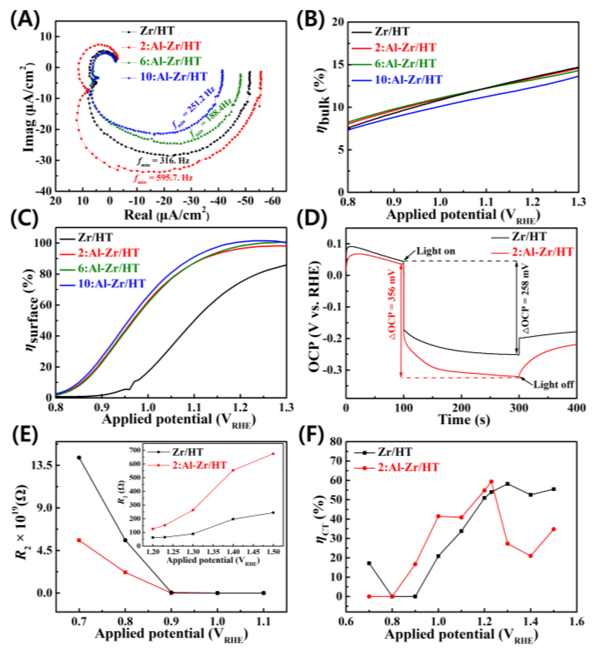
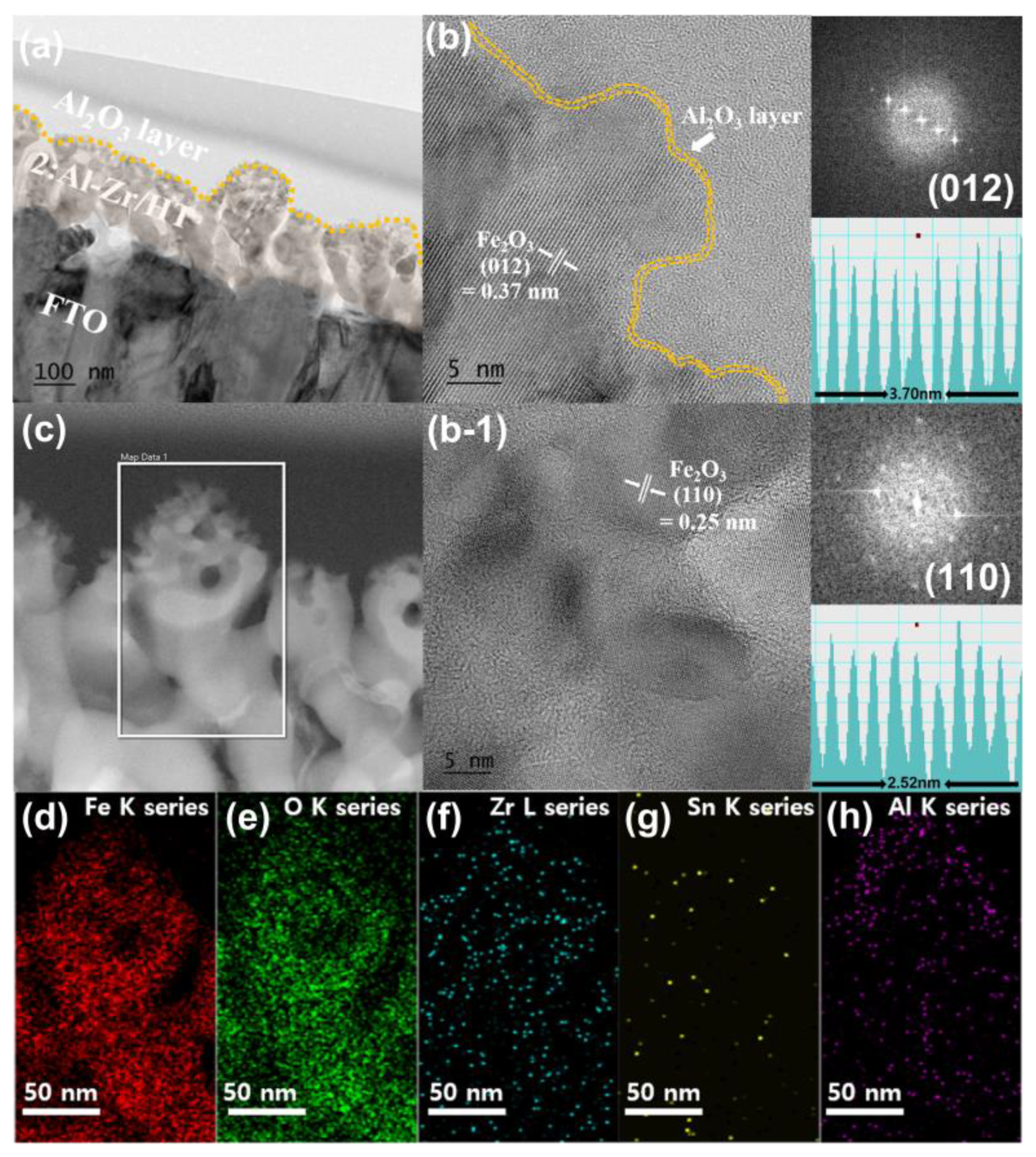
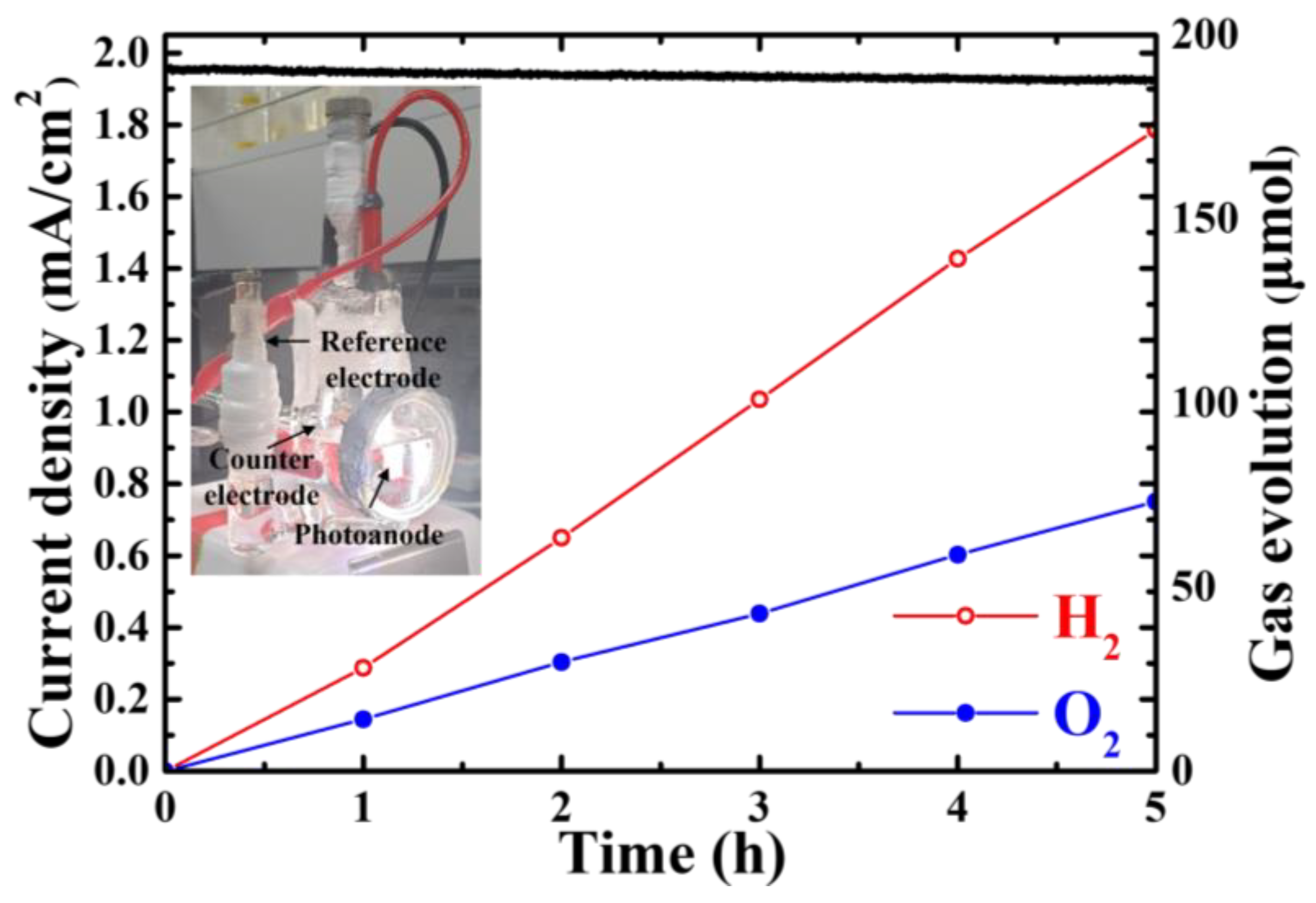
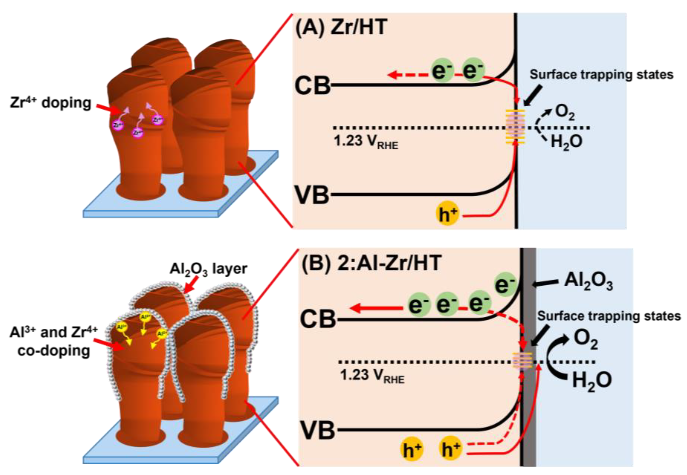
2. Results and Discussion

Figure S1 shows the XPS spectra of Al 2p and O 1s for the before quenched sample (2nm Al/Zr-FeOOH) to evaluate the oxidation state of Al in more depth. From the observation of Figure S1, it can be concluded that the composites of Al(OH)3 and Al2O3 exist on the surface of the 2nm Al/Zr-FeOOH photoanode. Here, the Al-layer sputtering time was adjusted to achieve Al-layer thicknesses of 2, 6 and 10 nm on the Zr-FeOOH films, followed by high-temperature quenching that induced the diffusion/doping of Al3+ into the Zr-doped Fe2O3 lattice. Meanwhile, the Al2O3 layer was formed on the surface of the Al/Zr co-doped Fe2O3 photoanode. The HR-FESEM analysis was used to evaluate the morphological characteristics of Al-layer sputtered Zr-FeOOH samples and x:Al-Zr/HT photoanodes, as depicted in Figure S2 and Figure 1, respectively. In comparison to the bare Zr-FeOOH sample, it is noticeable that after the Al sputtering was performed, the thicknesses of Al/Zr-FeOOH films increased. In addition, before quenching, there were no discernible changes in the morphology of the samples. Additionally, following the high-temperature quenching, the morphology of the as-prepared photoanodes was altered. This might be owing to the fact that the quenching process induces surface melting, migration and changes in surface energy. In comparison to the Zr/HT photoanode, the x:Al-Zr/HT photoanodes exhibit obvious changes in morphology, transitioning from nanorod to broccoli-shaped (Figure 1). This could be the result of the unintentional formation of an Al2O3 passivation layer, which modifies the morphology and covers the photoanode surface.
The phase and crystalline composition of the as-prepared x:Al-Zr/HT photoanodes were also investigated by synchrotron XRD (SR-XRD), measured at the BL5A beamline of PLS-II in Korea. Figure 2A shows the SR-XRD patterns of the Zr/HT and x:Al-Zr/HT photoanodes and the major diffraction peaks correspond to the hematite phase (JCPDS No. 33-0664 or ICSD collection code 15840), where ‘H’ denotes the hematite and no other peak was observed, with the exception of the FTO substrate peaks. The diffraction patterns are similar to each other, because the deposited Al thickness (or amount) is thinner than the initial Zr-FeOOH film thickness. Figure S3A displays two major peaks of hematite H(104) and H(110), and there is some variability in the peak intensity (as summarized in Figure S3B). The intensity of H(104) was slightly increased by the introduction of Al. It was maximized at a 2 nm thick Al deposited sample and then gradually decreased with further Al deposition. Meanwhile, there was no change in the crystallite size at all. The size of the crystallites is typically considered to be a significant parameter, as the sizes of the crystals determine whether the material is soft (small crystallites) or brittle (big crystallites) [26]. In addition, the lattice strain increases as the size of the crystallite increases. Lattice strain is a measurement of the distribution of lattice constants, such as lattice dislocations, which are caused by crystal defects/imperfections [27,28]. As can be seen from Figure S3B, there are no discernible changes in the crystallite size following Al co-doping, vividly indicating that the Al co-dopant does not induce lattice strain. The local structure spanned from a centering Fe atom could be revealed with EXAFS analysis in Figure S4. With Al sputtering, the only change is observed for the non-separable peak at 2−3 Å (denoted by *) which originates from Fe−M scattering (M=Fe, other metal atoms of Zr or Al or Sn) and Fe−O with long bond distances. As the dominant contribution comes from the Fe−M bonds, the reduced intensities for x:Al-Zr/HT is ascribed to weak Al backscatterers, which reside on the hematite lattice or the surface of the photoanode. XPS analysis was carried out to explore the chemical environment and compositions of the x:Al-Zr/HT photoanodes. As can be seen from the high-resolution XPS spectra of Al 2p (Figure 2B), there is one distinct peak at a binding energy (BE) of 73.9 eV, which corresponds to Al3+ in the Al2O3, vividly confirming the formation of the Al2O3 layer [29]. As the Al-layer sputtering time increases, so does the intensity of the Al 2p peak, which explicitly shows the formation of a thicker Al2O3 layer on the photoanode surface with Al-layer sputtering time. As shown in Figure 2C, the BEs of the two Fe 2p peaks that appeared at 724.5 and 710.9 eV were ascribed to Fe 2p1/2 and Fe 2p3/2, respectively, with a satellite peak at 719.3 eV, which represents the typical value of Fe3+ in Fe2O3 [18]. It is notable that there is not a satellite peak at around 715 eV in the Fe 2p region, which signifies that Fe2+ does not exist. Furthermore, Figure 2D shows the XPS spectra of Zr 3d and two Zr peaks at BEs of 181.38 and 183.5 eV are evident in all the measured x:Al-Zr/HT photoanodes, indicating the successful doping of Zr in the x:Al-Zr/HT photoanodes [30]. Importantly, the O 1s spectrum could be deconvoluted into two major peaks in x:Al-Zr/HT (Figure 2E), which correspond to the lattice oxygen at 530 eV (Fe–O and Al–O) and the surface-adsorbed water molecules at 532 eV [31,32]. Moreover, Figure S5 displays the Sn 3d XPS peak positioned at BE of 486.1 eV for Sn 3d5/2, implying the unintentional doping of Sn4+ from the FTO during the high-temperature quenching. The peak intensities of the Fe 2p, Zr 3d and Sn 3d spectra are observed to decrease as the Al-layer sputtering time (Al-layer thickness) increases. This is attributed to the formation of a thicker Al2O3 layer, which can prevent the detection of Fe 2p and Zr 3d peaks. In contrast, the fact that the O 1s peak intensity increases as the Al-layer sputtering time increases attests to the formation of an Al2O3 layer on the surface of the photoanode.
Figure 3A displays the photocurrent density–potential (JV) curves of the bare Zr/HT and x:Al-Zr/HT photoanodes in 1 M NaOH electrolyte under 1-sun illumination (AM 1.5G, 100 mW/cm2). The optimized 2:Al-Zr/HT photoanode exhibits a photocurrent density of 1.85 mA/cm2 at 1.23 V vs. RHE. In comparison with the bare Zr/HT (0.315 mA/cm2), the 2:Al-Zr/HT photoanode exhibits a 3-fold improved photocurrent density of 0.945 mA/cm2 at 1.0 VRHE, with a cathodic onset potential shift of 100 mV. This negative onset shifting is a result of the unintended complete formation of an Al2O3 passivation layer, which removes the surface defects and thus enhances the water oxidation at lower potentials. At a higher potential (above 1.35 VRHE), the photocurrent density of the 2:Al-Zr/HT photoanode is less than that of the Zr/HT photoanode. This is ascribed to the crucial effect of the Al2O3 overlayer, which may impede the transfer of holes from the photoanode to the electrolyte, thus decreasing the PEC performance [33]. Similarly, when the Al-layer sputtering thickness increases, the photocurrent decreases. This is due to the thicker Al2O3 layer hindering the migration of photogenerated holes for water oxidation. Table S1 illustrates the previous reports on Zr and Al mono-doping and co-doping strategies to improve the PEC performance of hematite photoanode. The Mott-Schottky plots of Zr/HT, 2:Al-Zr/HT, 6:Al-Zr/HT and 10:Al-Zr/HT photoanodes were also measured, as shown in Figure 3B. All the as-obtained photoanodes displayed positive slopes, indicating n-type semiconductor properties with electrons as the majority carriers. Zr/HT exhibits a charge carrier density of 1.84 × 1020 cm−3, while 2:Al-Zr/HT photoanode shows a much higher charge carrier density of 2.33 × 1020 cm−3, implying that the Al3+ is well doped into the lattice. This enhanced charge carrier density has the potential to improve the PEC performance by elevating the Fermi level. This results in more band bending, which improves the electric field in the space charge layer, hence decreasing electron-hole recombination [34]. It also accelerates the electrical conductivity of the photoanode, thereby enhancing the charge transport properties within the photoanode. However, as the Al-layer sputtering thickness increases, the charge carrier density decreases. This can be ascribed to the formation of a thicker Al2O3 layer, which can hinder the hole mobility from the photoanode to the electrolyte, thereby inducing charge recombination, and thus leading to lower charge carrier density. In addition, the Al-layer sputtered samples show a cathodic shift in flat band potential related to the Zr/HT. A negative shift of the flat band potential generally results in a cathodic shift of the onset potential obtained from the JV curve (Figure 3A).
The charge transport characteristics and interfacial reaction resistance of the as-prepared photoanodes were investigated using electrochemical impedance spectroscopy (EIS), at 1.0 V vs. RHE under 1-sun illumination conditions, in order to gain a better understanding of the enhancement of the PEC properties in relation to the Al-layer with varying thicknesses (Figure 3C). Nyquist plots were fitted with a two resistance and capacitance (RC) circuit model, as represented in the inset of Figure 3C, and Table S2 provides the results, in which Rs is the series resistance comprised of electrolyte, FTO substrate and external contact; R1 and R2 denote the charge-transfer resistances in the bulk and at the photoanode/electrolyte interface, respectively; while CPE1 and CPE2 designate the capacitances associated with the bulk of the photoanode and surface states at the electrode/electrolyte interface, respectively. The R1 values of the Al co-doped samples are greater than that of the bare Zr/HT photoanode, which might be due to the Al co-doping generating the bulk electronic trapping states. A similar phenomenon has been reported in a previous study [22]. Meanwhile, it is obvious that the Al co-doped photoanodes exhibit lower R2 values, compared to that of Zr/HT, indisputably demonstrating Al2O3 formation on the photoanode surface, which can passivate the surface defects, hence reducing the charge transfer resistance at the photoelectrode/electrolyte interface. The applied bias photon-to-current efficiencies (ABPE) of Zr/HT and x:Al–Zr/HT photoanodes were calculated using the following equation [35]:
ABPE   ( % ) = J × [ ( 1.23 V app ) / P incident ] × 100
where Vapp is the applied potential (vs. RHE), J is the photocurrent density (mA/cm2) and Pincident is the intensity of incident light (mW cm−2). As shown in Figure S6A, the maximum ABPE value for the 2:Al-Zr/HT photoanode is 0.23% (at 1.03 V vs. RHE), which is approximately 2-fold higher than that of the Zr/HT (0.12% at 1.09 V vs. RHE) photoanode. This enhancement was due to the formation of the Al2O3 passivation layer on the surface, which improved the charge separation and transfer process between the semiconductor and electrolyte interface [36]. In addition, an obvious cathodic onset shift signifies the surface passivation effect of the Al2O3 layer. Figure S6B shows the long-term stability test conducted at 1.23 V vs. RHE for the Zr/HT and 2:Al–Zr/HT photoanodes. The 2:Al-Zr/HT photoanode retains 98% of its initial photocurrent after 1 h of illumination.
The PL spectrum of the examined iron oxide photoanodes showed the most emissions around the absorption edge region, including minor extended emissions beyond 650 nm (Inset of Figure 3D). This PL characteristic implies that most of the photoexcited carriers directly recombine in these photoanodes, including some minor contributions to trapped carrier recombination [37,38]. To study the excited state carrier recombination dynamics, time-resolved PL decays were recorded for the hematite phases with/without Al (Figure 3(Da)). These observed PL decays were well fitted by three-lifetime sub-components (Table S3), indicating that multiple recombination routes exist in the examined photoanodes. The two fast components (τ1 and τ2) are similarly conserved in lifetimes and their amplitude contributions with/without Al introduction, whereas the longest lifetime component (τ3) shows meaningful variations: reduced lifetime and increased contribution, with the increasing Al-layer thickness from 2 to 10 nm. This variation of the τ3 component is linearly correlated with the reduction of average PL lifetime, indicating the critical role of the τ3 component to the entire excited-state carrier recombination dynamics of the hematite phase with Al coating. According to the previous literature, the fast lifetime components are ascribed to carrier recombinations in the bulk phase, whereas the longest lifetime component can be assigned to recombinations through trapped electronic states at the surface and interface [39,40,41]. Thus, this reduced lifetime indicates fast electron transport and effective electron extraction [42]. This can be due to the higher thickness of an Al2O3 layer, as depicted in Figure 2B, which hinders the efficient hole migration from the photoanode to the electrolyte for water oxidation. One additional point is that the randomly-spared bright color centers shown in the Zr/HT were mostly removed after the Al coating (Figure 3(Db,Dc)). Remembering the higher PEC performance with Al coating, the observed enhanced PEC activity with Al might be due to the efficient passivation of emissive color centers, as well as nonradiative facile charge transfer characteristics at the surface. Furthermore, a slightly reduced PEC performance with increasing Al thickness is also due to the increased contribution (A3) of surface emission (Table S3), which was clearly demonstrated as brightened emissions in the PL lifetime images (Figure 3(Dd,De)).
The electron transport process in the photoanode is another vital feature to assess the PEC performance. Intensity-modulated photocurrent spectroscopy (IMPS) analysis is an effective technique to reveal the electron transfer dynamics and the electron transport time (τet) can be computed using the equation:
τ e t = ( 2 π f m i n ) 1
where fmin is the frequency at the minimum imaginary component in the IMPS spectra. As depicted in Figure 4A, the fmin values for the bare Zr/HT, 2:Al-Zr/HT, 6:Al-Zr/HT and 10:Al-Zr/HT photoanodes are 316, 595.7, 188.4 and 251.2 Hz, respectively, at 1.0 VRHE. The 2:Al-Zr/HT exhibits the lowest electron transport time (Table S4), indicating that the electron transport is enhanced due to the highest donor density, thereby increasing the PEC performance. Further, the bulk charge separation efficiencies (ηbulk) were calculated for the as-studied samples (Figure 4B). The ηbulk of the bare Zr/HT photoanode is ~10.8% at 1.0 V vs. RHE. Upon Al sputtering, the ηbulk of x:Al-Zr/HT is still similar to 10.9% at 1.0 V vs. RHE, indicating the formation of bulk trapping energy levels caused by the Al co-doping, as discussed earlier in the EIS analysis. To understand the impact of Al-sputtering on the surface properties, we measured the surface charge separation efficiency (ηsurface), as shown in Figure 4C. The ηsurface increases to 63% for the 2:Al/Zr-HT photoanode at 1.0 VRHE, which is almost 4-fold higher than that of the bare Zr-HT photoanode, explicitly demonstrating that the formation of the Al2O3 passivation layer eradicates the surface trapping states, thereby enhancing the charge separation. As a consequence, the photocurrent density is enhanced at lower potentials. Moreover, to gain insights into the built-in electric field, the open-circuit potential (OCP) curves of the Zr-HT and 2:Al/Zr-HT photoanodes were measured in the dark and under 1-sun illumination conditions, respectively. As depicted in Figure 4D, when the light is illuminated, the OCPs of the Zr-HT and 2:Al/Zr-HT photoanodes shift cathodically, which is compatible with the n-type semiconductor properties and is in good accordance with the MS result (Figure 3B). In addition, the improved ΔOCP (ΔOCP = OCPdark − OCPlight) value for 2:Al/Zr-HT photoanode implies that there is increased band bending at the interface between the photoanode and electrolyte, which stands for improved electron-hole separation and which is consistent with the sharper band bending caused by the higher donor density of 2:Al-Zr/HT photoanode [43,44]. This enhanced ΔOCP leads to a higher photocurrent density, as well as a greater cathodic shift in the onset potential.
In order to obtain further insight into the charge-transfer mechanism at the photoanode/electrolyte interface at various potentials, EIS analysis was conducted from 0.7–1.5 V vs. RHE for both the bare Zr/HT and optimized 2:Al-Zr/HT photoanodes under 1-sun illumination (Figure S7). All Nyquist plots of both samples were fitted with a circuit model of the inset of Figure S7. As shown in Figure 4E, the 2:Al-Zr/HT photoanode exhibits apparently decreased R2 values at lower potentials of 0.7–1.1 VRHE, demonstrating that the water oxidation kinetics of the 2:Al-Zr/HT photoanode have been vastly enhanced, thanks to the passivation effect of the unintended Al2O3 layer formation. We estimated the charge-transfer efficiencies (ηCT) of the Zr/HT and 2:Al-Zr/HT photoanodes to explicate the charge–transfer mechanism at the semiconductor-electrolyte interface (SEI), using the following equation [45]:
η CT   ( % ) = k ct k ct + k trapping = R 1 R 1 + R 2
where kct and ktrapping are the rate constants of charge transfer and trapping, respectively. As can be seen from Figure 4F, it would appear that the 2:Al-Zr/HT photoelectrode shows a higher ηCT than the Zr/HT photoanode across the potential window 0.7–1.23 VRHE. In particular, at 1.0 VRHE, the 2:Al-Zr/HT displays a 125% enhanced charge-transfer efficiency, compared with the Zr/HT photoanode. This intensification of ηCT unequivocally reveals that the Al co-doping improved the bulk charge transport to the electrode surface, thus increasing the charge transfer to the electrolyte, as well as the Al2O3 layer passivating the surface defects and thereby accelerating the hole mobility towards electrolyte at the SEI. At higher potentials (above 1.23 VRHE), the ηCT being lower for the 2:Al-Zr/HT than Zr/HT is attributed to the Al2O3 overlayer restricting the hole transfer to the electrolyte, which correlates well with the JV curve and R2 values. Furthermore, to acquire a better understanding of the surface charge transfer characteristics through SEI, we measured the transient photocurrent measurements under chopped light illumination at 1.0 VRHE (Figure S8A). As depicted in Figure S8B, the transient decay time (τ) of the optimized 2:Al-Zr/HT photoanode (4.17 s) is longer than that of the Zr/HT (4.12 s). In addition, we conducted the light on/off chopping experiment over the potential window of 0.7–1.5 VRHE for the as-obtained Zr/HT and 2:Al-Zr/HT photoelectrodes. From the anodic spike, we were able to gain insight into the accumulation of holes in the space charge layer without contributing to water oxidation. Figure S9 illustrates the relative differences between the intensities of the anodic spikes and the steady-state photocurrent of the photoanodes (ID). As can be seen, it is evident that the ID of the 2:Al-Zr/HT shows lower at the low potentials. These transient decay time and ID measurement results explicitly disclose that the 2:Al-Zr/HT photoanode improved the charge transfer kinetics on the surface as a consequence of the suppression of the surface charge recombination by the formation of an Al2O3 passivation layer.
Transmission electron microscopy (TEM) analysis was conducted to disclose the surface micromorphology of the 2:Al-Zr/HT photoanode and Figure 5a displays a broccoli-shaped morphology of the photoanode, as we discussed in the HR-FESEM. Figure 5b depicts the high-resolution TEM (HR-TEM) image of the 2:Al-Zr/HT and the ultrathin layer of Al2O3 is indicated by the dark yellow dotted line. As can be seen from Figure 5b,b-1, the lattice fringes of 0.37 and 0.25 nm are indexed to the (012) and (110) planes of Fe2O3, respectively. In addition, the selective area electron diffraction (SAED) patterns signify the crystalline phase of hematite. As noted from the scanning transmission electron microscopy-energy dispersive spectrometry (STEM-EDS) mapping (Figure 5d–h), the distributions of the Fe and O elements were even. In addition, Zr and Al were dispersed throughout the bulk of the photoanode, revealing the successful doping of Zr and Al. Further, Al was found to be mainly disseminated on the surface, which is corroborative of the fact that the Al2O3 layer has been well formed and is covering the photoanode. Moreover, the TEM-EDS line profile and associated EDS spectra were acquired, as presented in Figure S10a,b. Further, Figure S10c–e illustrate the point EDS spectra obtained at three different points of the 2:Al-Zr/HT. It is evident that the Al content is higher on the surface of the photoanode (Figure S10c,f), which further confirms the presence of the Al2O3 layer. Lastly, the optimized 2:Al-Zr/HT photoanode was treated with cobalt phosphate (Co-Pi) cocatalyst using the electrodeposition method to check the stability of the photoanode. The CoPi/2:Al-Zr/HT photoanode shows 1.98 mA/cm2 at 1.23 VRHE. After 5 h of continuous illumination, the CoPi/2:Al-Zr/HT photoelectrode attained 73 and 174 µmol of O2 and H2 gases, respectively (Figure 6). In addition, we can observe that the CoPi/2:Al-Zr/HT photoanode retained almost 96% of its initial photocurrent after 5 h illumination, signifying the excellent stability of the photoanode for water oxidation.
Scheme 1 summarizes and illustrates the charge-transfer mechanisms of the Zr/HT and 2:Al-Zr/HT, based on the experimental evidence discussed above. Under light irradiation, electrons and holes are generated, in which most of the photoinduced holes recombine with the photogenerated electrons at the electrode and electrolyte interfaces. As can be observed from Scheme 1A, severe photogenerated electron-hole recombination ensues in the surface defect sites (surface trapping states) at the SEI, which restricts the charge transfer to the electrolyte for water oxidation. On the other hand, the Al and Zr co-doped Fe2O3 photoelectrode reduced the surface recombination by the Al2O3 passivation layer and increased the charge density, due to Al co-doping (Scheme 1B), resulting in faster electron transfer in the bulk of the photoanode (Figure 4A). As per the OCP analysis (Figure 4D), the enlarged band bending at the SEI for the 2:Al-Zr/HT photoanode is evident; as a consequence, it accelerated both the efficient charge separation and the charge-transfer rate. As a result of the passivation of surface defects/surface trapping states, photogenerated holes are hastened to the electrolyte, which allows for effective water oxidation.

3. Materials and Methods

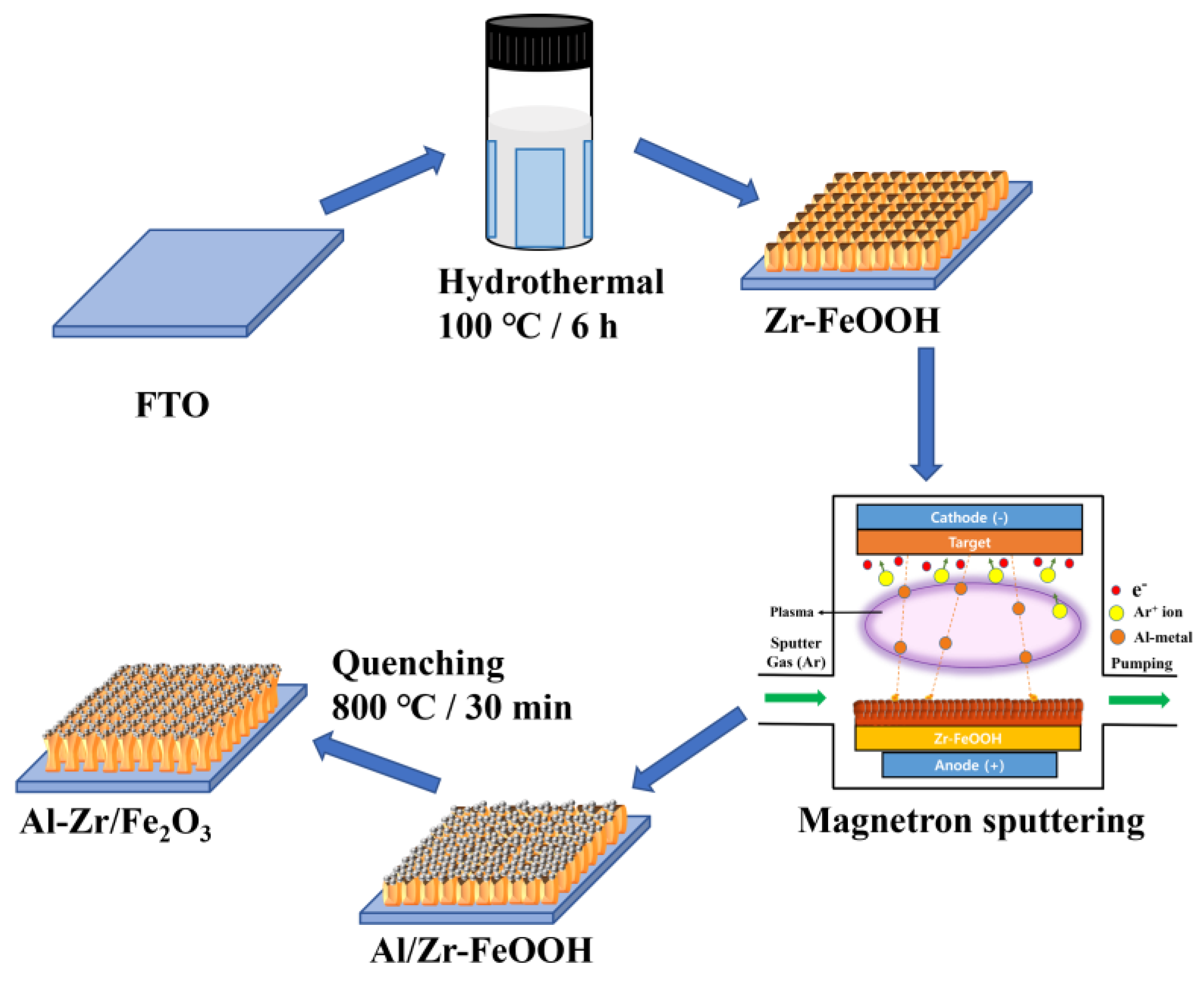
3.1. Synthesis of Zr-Fe2O3 Nanocoral Photoanodes

Zr-doped Fe2O3 photoanode (Zr/HT) nanorods (NRs) were synthesized using an in-situ Zr-doping method [30]. As is typical, cleaned FTO substrates were vertically aligned in a 20 mL vial, which contained 10 mL of an aqueous solution of 12.6 mg FeCl3·6H2O and 0.85 g NaNO3. The FTO substrates were ultrasonically cleaned with deionized water, acetone and ethanol, prior to being kept in a vial. The pH of the above precursor solution was adjusted to 1.5 by adding HCl. Then, the reactor vials were placed in an oven at 100 °C for 6 h. After being allowed to cool naturally to room temperature, the samples (Zr-FeOOH) were rinsed in deionized water and dried under purging with air. Following that, the dried samples were quenched at 800 °C for 10 min to form the Zr-doped Fe2O3 photoanode.

3.2. Preparation of Al and Zr Co-Doped Fe2O3 via Magnetron Sputtering Method

Initially, the Zr-FeOOH NRs were formed on FTO glass via a facile hydrothermal method. Next, an Al-layer was deposited onto the Zr-FeOOH NRs on the FTO substrate via radio-frequency magnetron sputtering from a pure Al metallic target. Prior to deposition, the sputtering chamber was initially evacuated out to a base pressure of 3 × 10⁻⁶ Torr and then the working (or deposition) pressure was set to 5 mTorr. The thickness (or amount) of the Al-layer on Zr-FeOOH NRs was precisely controlled by changing the sputter deposition time at a deposition power of 2.0 W/cm2 (91 W of total power for a 3-inch target). High purity (5 N) Ar gas was introduced to the sputtering chamber as a sputtering gas, and no oxygen was introduced to suppress an oxide formation during the sputter deposition. The sample temperature was maintained at 30 °C and all other conditions were fixed for all samples. A series of Al layers was deposited onto Zr-FeOOH films with three Al thicknesses of (2, 6 and 10) nm and these samples were labelled as 2nm Al/Zr-FeOOH, 6nm Al/Zr-FeOOH, and 10nm Al/Zr-FeOOH, respectively. However, a native oxide formation was inevitable after removing the samples from the sputtering chamber. Furthermore, the samples were quenched at 800 °C, for 10 min, in a box furnace in order to induce Al3+ doping into the transformed hematite. Scheme 2 illustrates the sputter-deposited Al and Zr co-doped Fe2O3 formation process. The samples were denoted as x:Al-Zr/HT (x = 2, 6, 10), where x represents the sputtered Al thickness in ‘nm’.

3.3. Deposition of Cobalt Phosphate (Co-Pi) Cocatalyst on Al-Zr/Fe2O3 Photoanode

Cobalt phosphate (Co-Pi) cocatalyst was coated on an optimized 2:Al-Zr/HT photoanode using the electrodeposition method. The 2:Al-Zr/HT photoanode was used as a working electrode and immersed in 0.5 mM cobalt nitrate and 0.1 M potassium phosphate electrolyte solution. Ag/AgCl and Pt mesh were used as a reference and counter electrodes, respectively. The Co-Pi layer was deposited at a constant voltage of 1.9 V vs. RHE for 5 min. After the deposition, the electrode was gently rinsed with deionized water and dried naturally. The Co-Pi deposited 2:Al-Zr/HT photoanode was further named as CoPi/2:Al-Zr/HT.

3.4. PEC Water Splitting

PEC water splitting was carried out in a specially designed three-electrode reactor cell, which has a volume of 130 mL, with a quartz flat lens attached to the front. The CoPi/2:Al-Zr/HT photoanode, Hg/HgO (1 M NaOH) and Pt mesh were used as working, reference and counter electrodes, respectively. An aqueous solution of 1 M NaOH of pH 13.6 was filled in a reactor as an electrolyte. In order to remove the dissolved oxygen from the electrolyte, the solution was purged with 99.9% N2 gas for 2 h before the start of the PEC water splitting experiments. Then, the photoanode was illuminated, with AM 1.5G light (100 mW cm−2) at 1.23 V vs. RHE, during the photoelectrochemical water splitting, with an illumination area of 1 cm2. The evolved gases, such as O2 on the photoanode and H2 on the Pt counter electrode, were quantified using a gas chromatograph equipped with a thermal conductivity detector (GC-TCD, Agilent 7820, Agilent Technologies, Inc., Santa Clara, CA, United States), with a 5 Å molecular sieve column and Ar carrier gas.

4. Conclusions

In summary, we successfully developed the Zr/Al co-doped Fe2O3 photoanode via the Al-layer deposition onto the Zr-FeOOH samples using a magnetron sputtering method with a controllable thickness. During the high-temperature quenching, the Al3+ diffused into the Zr/HT photoanode, whereas the Al2O3 layer formed on the surface. The PEC properties with different Al-layer thicknesses were thoroughly deliberated. The optimized 2 nm Al sputtered Zr/HT photoanode exhibited 200% enhanced photocurrent density (0.945 mA/cm2) at 1.0 V vs. RHE, in comparison with the bare Zr/HT (0.315 mA/cm2) photoanode, as well as the fortuitous Al2O3 layer causing a 100 mV cathodic shift. Furthermore, the Al2O3 layer passivated the surface trapping states, which resulted in an improvement in the surface charge separation and charge transfer efficiencies. The transient decay time and ID data revealed that the Al2O3 passivation layer decreased the surface charge recombination and reduced the accumulated holes, which in turn accelerated the water oxidation kinetics at a lower potential. This concept proposes a simultaneous co-doping strategy in conjunction with a passivation overlayer for the photoanode in PEC water splitting.

Supplementary Materials

The following supporting information can be downloaded at: https://www.mdpi.com/article/10.3390/catal12111467/s1, Figure S1: The XPS spectra of (A) Al 2p and (B) O 1s for 2nm Al/Zr-FeOOH. Figure S2: FESEM image (top and cross-sectional view) of Al deposited photoanode before quenching. (A,a) Zr-FeOOH, (B,b) 2nm Al/Zr-FeOOH, (C,c) 6nm Al/Zr-FeOOH, (D,d) 10nm Al/Zr-FeOOH. Figure S3: (A) Diffraction profiles near the two major H(104) and H(110) peaks. (B) Integrated intensity ratio of H(104) vs. H(110) peak and the crystallite size calculated from the H(104) peak. Figure S4: Fourier-transformed spectra of k3-weighted EXAFS functions for the Fe K-edges of x:Al-Zr/HT photoanodes. Figure S5: XPS narrow scan spectra of Sn 3d of x:Al-Zr/HT photoanodes. Figure S6: (A) ABPE as a function of applied potential for Zr/HT and x:Al-Zr/HT photoanodes and (B) long-term stability at 1.23 V vs. RHE using 1 M NaOH electrolyte for Zr/HT and x:Al-Zr/HT photoanodes. Figure S7: Nyquist plots for (A) Zr/HT and (B) 2:Al-Zr/HT photoanodes obtained at 0.7–1.5 VRHE. Figure S8: (A) Transient photocurrent response and (B) anodic transient decay time of Zr/HT and 2:Al-Zr/HT photoanode measured at 1.0 VRHE in 1 M NaOH electrolyte under 1-sun illumination condition. Figure S9: The plots of Id values vs. Potential for Zr/HT and 2:Al-Zr/HT photoanode. Figure S10: (a,b) Line profile obtained from TEM-EDS analysis for the 2:Al-Zr/HT photoanode, and (c–e) cross-sectional TEM image of 2:Al-Zr/HT photoanode with their respective EDS spectra (f–h). Table S1: Comparative photocurrents density results of hematite photoanodes at 1.23 V vs. RHE with previous studies. Table S2: Electrochemical impedance spectroscopy (EIS) fitting parameters at 1.0 V vs. RHE for Zr/HT, 2:Al-Zr/HT, 6:Al-Zr/HT and 10:Al-Zr/HT photoanodes. Table S3: PL lifetime parameters of the examined Zr/HT, 2:Al-Zr/HT, 6:Al-Zr/HT and 10:Al-Zr/HT photoanodes. Table S4: Frequency at the minimum imaginary component (fmin) and average electron transport time in the IMPS spectra for Zr/HT, 2:Al-Zr/HT, 6:Al-Zr/HT and 10:Al-Zr/HT photoanodes [8,15,16,22,29,37,38,40,46,47,48,49,50,51,52,53,54,55,56,57].

Author Contributions

Conceptualization, T.S.K., P.A., H.H.L. and J.S.J.; methodology, T.S.K. and J.S.J.; validation, T.S.K., P.A. and J.S.J.; formal analysis, T.S.K., J.B.H., S.H.C., W.-S.C. and H.H.L.; investigation, T.S.K., P.A., S.H.C., W.-S.C., H.H.L. and J.S.J.; resources, J.S.J.; data curation, T.S.K., J.B.H., S.H.C., W.-S.C. and H.H.L.; writing—original draft preparation T.S.K. and P.A.; writing—review and editing, T.S.K., P.A. and J.S.J.; visualization, T.S.K., P.A. and J.S.J.; supervision, J.S.J.; project administration, J.S.J.; funding acquisition, S.H.C., H.H.L. and J.S.J. All authors have read and agreed to the published version of the manuscript.

Funding

This research was funded by Korean National Research Foundation (2021R1A2C1095669 and 2021R1F1A1049366) and the Korea Government (MSIP).

Data Availability Statement

The data presented in this study are available on request from the corresponding author.

Conflicts of Interest

The authors declare no conflict of interest.

References

  1. Li, Y.; Dai, X.; Bu, Y.; Zhang, H.; Liu, J.; Yuan, W.; Guo, X.; Ao, J.P. Photoelectrochemical Performance Improving Mechanism: Hybridization Appearing at the Energy Band of BiVO4 Photoanode by Doped Quantum Layers Modification. Small 2022, 18, 2200454. [Google Scholar] [CrossRef] [PubMed]
  2. Khan, A.Z.; Kandiel, T.A.; Abdel-Azeim, S.; Jahangir, T.N.; Alhooshani, K. Phosphate ions interfacial drift layer to improve the performance of CoFe−Prussian blue hematite photoanode toward water splitting. Appl. Catal. B 2022, 304, 121014. [Google Scholar] [CrossRef]
  3. Mukhtar, F.; Munawar, T.; Nadeem, M.S.; Khan, S.A.; Koc, M.; Batool, S.; Hasan, M.; Iqbal, F. Enhanced sunlight-absorption of Fe2O3 covered by PANI for the photodegradation of organic pollutants and antimicrobial inactivation. Adv. Powder Technol. 2022, 33, 103708. [Google Scholar] [CrossRef]
  4. Mukhtar, F.; Munawar, T.; Nadeem, M.S.; Hasan, M.; Hussain, F.; Nawaz, M.A.; Iqbal, F. Multi metal oxide NiO-Fe2O3-CdO nanocomposite-synthesis, photocatalytic and antibacterial properties. Appl. Phys. A 2020, 126, 558. [Google Scholar] [CrossRef]
  5. Wang, H.; Hu, Y.L.; Song, G.L.; Zheng, D.J. Intrinsic and extrinsic doping to construct hematite nanorod pn homojunctions for highly efficient PEC water splitting. Chem. Eng. J. 2022, 435, 135016. [Google Scholar] [CrossRef]
  6. Mukhtar, F.; Munawar, T.; Nadeem, M.S.; ur Rehman, M.N.; Khan, S.A.; Koc, M.; Batool, S.; Hasan, M.; Iqbal, F. Dual Z-scheme core-shell PANI-CeO2-Fe2O3-NiO heterostructured nanocomposite for dyes remediation under sunlight and bacterial disinfection. Environ. Res. 2022, 215, 114140. [Google Scholar] [CrossRef]
  7. Ashraf, M.; Khan, I.; Usman, M.; Khan, A.; Shah, S.S.; Khan, A.Z.; Saeed, K.; Yaseen, M.; Ehsan, M.F.; Tahir, M.N.; et al. Hematite and magnetite nanostructures for green and sustainable energy harnessing and environmental pollution control: A review. Chem. Res. Toxicol. 2019, 33, 1292–1311. [Google Scholar] [CrossRef]
  8. Kleiman-Shwarsctein, A.; Huda, M.N.; Walsh, A.; Yan, Y.; Stucky, G.D.; Hu, Y.S.; Al-Jassim, M.M.; McFarland, E.W. Electrodeposited aluminum-doped α-Fe2O3 photoelectrodes: Experiment and theory. Chem. Mater. 2010, 22, 510–517. [Google Scholar] [CrossRef]
  9. Saremi-Yarahmadi, S.; Wijayantha, K.U.; Tahir, A.A.; Vaidhyanathan, B. Nanostructured α-Fe2O3 electrodes for solar driven water splitting: Effect of doping agents on preparation and performance. J. Phys. Chem. C. 2009, 113, 4768–4778. [Google Scholar] [CrossRef]
  10. Li, L.; Liu, C.; Qiu, Y.; Mitsuzak, N.; Chen, Z. The influence of the hydrothermal temperature and time on morphology and photoelectrochemical response of α-Fe2O3 photoanode. J. Alloy. Compd. 2017, 696, 980–987. [Google Scholar] [CrossRef]
  11. Pu, A.; Deng, J.; Hao, Y.; Sun, X.; Zhong, J. Thickness effect of hematite nanostructures prepared by hydrothermal method for solar water splitting. Appl. Surf. Sci. 2014, 320, 213–217. [Google Scholar] [CrossRef]
  12. Nadeem, M.S.; Munawar, T.; Mukhtar, F.; ur Rahman, M.N.; Riaz, M.; Hussain, A.; Iqbal, F. Hydrothermally derived co, Ni co-doped ZnO nanorods; structural, optical, and morphological study. Opt. Mater. 2021, 111, 110606. [Google Scholar] [CrossRef]
  13. Bouhjar, F.; Mollar, M.; Chourou, M.L.; Marí, B.; Bessais, B. Hydrothermal synthesis of nanostructured Cr-doped hematite with enhanced photoelectrochemical activity. Electrochim. Acta. 2018, 260, 838–846. [Google Scholar] [CrossRef]
  14. Dhandole, L.K.; Anushkkaran, P.; Hwang, J.B.; Chae, W.S.; Kumar, M.; Lee, H.H.; Choi, S.H.; Jang, J.S.; Lee, J.S. Microwave-assisted metal-ion attachment for ex-situ zirconium doping into hematite for enhanced photoelectrochemical water splitting. Renew. Energy 2022, 189, 694–703. [Google Scholar] [CrossRef]
  15. Kang, K.; Zhang, H.; Kim, J.H.; Byun, W.J.; Lee, J.S. An in situ fluorine and ex-situ titanium two-step co-doping strategy for efficient solar water splitting by hematite photoanodes. Nanoscale Adv. 2022, 4, 1659–1667. [Google Scholar] [CrossRef] [PubMed]
  16. Zhu, Q.; Yu, C.; Zhang, X. Ti, Zn co-doped hematite photoanode for solar driven photoelectrochemical water oxidation. J. Energy Chem. 2019, 35, 30–36. [Google Scholar] [CrossRef] [Green Version]
  17. Zandi, O.; Hamann, T.W. Determination of photoelectrochemical water oxidation intermediates on haematite electrode surfaces using operando infrared spectroscopy. Nat. Chem. 2016, 8, 778–783. [Google Scholar] [CrossRef]
  18. Zhang, S.; Liu, Z.; Chen, D.; Yan, W. An efficient hole transfer pathway on hematite integrated by ultrathin Al2O3 interlayer and novel CuCoOx cocatalyst for efficient photoelectrochemical water oxidation. Appl. Catal. B 2020, 277, 119197. [Google Scholar] [CrossRef]
  19. Hisatomi, T.; Le Formal, F.; Cornuz, M.; Brillet, J.; Tétreault, N.; Sivula, K.; Grätzel, M. Cathodic shift in onset potential of solar oxygen evolution on hematite by 13-group oxide overlayers. Energy Environ. Sci. 2011, 4, 2512–2515. [Google Scholar] [CrossRef] [Green Version]
  20. Wang, Z.; Fan, F.; Wang, S.; Ding, C.; Zhao, Y.; Li, C. Bridging surface states and current–potential response over hematite-based photoelectrochemical water oxidation. RSC Adv. 2016, 6, 85582–85586. [Google Scholar] [CrossRef]
  21. Cots, A.; Gómez, R. Ytterbium modification of pristine and molybdenum-modified hematite electrodes as a strategy for efficient water splitting photoanodes. Appl. Catal. B 2017, 219, 492–500. [Google Scholar] [CrossRef] [Green Version]
  22. Hwang, J.B.; Dhandole, L.K.; Anushkkaran, P.; Chae, W.S.; Choi, S.H.; Lee, H.H.; Jang, J.S. Microwave-assisted surface attachment of aluminium ions on in situ diluted titanium-doped hematite photoanodes for efficient photoelectrochemical water-splitting. Sustain. Energy Fuels 2022, 6, 3056–3067. [Google Scholar] [CrossRef]
  23. Nakrela, A.; Benramdane, N.; Bouzidi, A.; Kebbab, Z.; Medles, M.; Mathieu, C. Site location of Al-dopant in ZnO lattice by exploiting the structural and optical characterization of ZnO: Al thin films. Results Phys. 2016, 6, 133–138. [Google Scholar] [CrossRef] [Green Version]
  24. Son, M.K.; Seo, H.; Watanabe, M.; Shiratani, M.; Ishihara, T. Characteristics of crystalline sputtered LaFeO3 thin films as photoelectrochemical water splitting photocathodes. Nanoscale 2020, 12, 9653–9660. [Google Scholar] [CrossRef] [PubMed]
  25. Kim, S.; Anushkkaran, P.; Chae, W.S.; Choi, S.H.; Kumar, M.; Cho, M.; Mahadik, M.A.; Lee, H.H.; Jang, J.S. Influence of ZnO Magnetron Sputtering on Controlled Buildout of Zirconium-Doped ZnFe2O4/Fe2O3 Heterojunction Photoanodes for Photoelectrochemical Water Splitting. ACS Appl. Energy Mater. 2022, 5, 915–929. [Google Scholar] [CrossRef]
  26. Murthy, N.S. Scattering techniques for structural analysis of biomaterials. In Characterization of Biomaterials; Elsevier: Amsterdam, The Netherlands, 2013; pp. 34–72. [Google Scholar]
  27. Kumar, D.; Singh, M.; Singh, A.K. Crystallite size effect on lattice strain and crystal structure of Ba1/4Sr3/4MnO3 layered perovskite manganite. AIP Conf. Proc. 2018, 1953, 030185. [Google Scholar]
  28. Mishra, S.K.; Roy, H.; Lohar, A.K.; Samanta, S.K.; Tiwari, S.; Dutta, K. A comparative assessment of crystallite size and lattice strain in differently cast A356 aluminium alloy. IOP Conf. Ser. Mater. Sci. Eng. 2015, 75, 012001. [Google Scholar] [CrossRef] [Green Version]
  29. Fan, Z.; Xu, Z.; Yan, S.; Zou, Z. Tuning the ion permeability of an Al2O3 coating layer on Fe2O3 photoanodes for improved photoelectrochemical water oxidation. J. Mater. Chem. 2017, 5, 8402–8407. [Google Scholar] [CrossRef]
  30. Hwang, J.B.; Kim, S.; Chae, W.S.; Pathan, H.M.; Mahadik, M.A.; Jang, J.S. Engineering of cobalt oxide-integrated nitric acid-functionalized Zr-Fe2O3 nanocoral photoanodes for photoelectrochemical water splitting. Korean J. Chem. Eng. 2021, 38, 1149–1160. [Google Scholar] [CrossRef]
  31. Jiang, M.; Wu, Z.; Zhang, X.; Cai, Y.; Wang, W.; Liang, Y. Synergetic effect of surface plasmon resonance and Schottky junction to drastically boost solar-driven photoelectrochemical hydrogen production and photocatalytic performance of CdS/Al nanorod arrays. Energy Convers. Manag. 2022, 268, 115978. [Google Scholar] [CrossRef]
  32. Cao, X.; Wen, P.; Ma, R.; Liu, Y.; Sun, S.; Ma, Q.; Zhang, P.; Qiu, Y. Ni2P nanocrystals modification on Ta:α-Fe2O3 photoanode for efficient photoelectrochemical water splitting: In situ formation and synergistic catalysis of Ni2P@NiOOH cocatalyst. Chem. Eng. J. 2022, 449, 137792. [Google Scholar] [CrossRef]
  33. Subramanian, A.; Mahadik, M.A.; Park, J.W.; Jeong, I.K.; Chung, H.S.; Lee, H.H.; Choi, S.H.; Chae, W.S.; Jang, J.S. An effective strategy to promote hematite photoanode at low voltage bias via Zr4+/Al3+ codoping and CoOx OER co-catalyst. Electrochim. Acta 2019, 319, 444–455. [Google Scholar] [CrossRef]
  34. Tavazohi, A.; Abdizadeh, H.; Golobostanfard, M.R. Hierarchical mesoporous SnO2/BiVO4 photoanode decorated with Ag nanorods for efficient photoelectrochemical water splitting. Int. J. Hydrog. Energy 2022, 47, 18992–19004. [Google Scholar] [CrossRef]
  35. Liu, C.; Qiu, Y.; Wang, F.; Wang, K.; Liang, Q.; Chen, Z. Design of core–shell-structured ZnO/ZnS hybridized with graphite-like C3N4 for highly efficient photoelectrochemical water splitting. Adv. Mater. Interfaces 2017, 4, 1700681. [Google Scholar] [CrossRef]
  36. Liu, R.; Zheng, Z.; Spurgeon, J.; Yang, X. Enhanced photoelectrochemical water-splitting performance of semiconductors by surface passivation layers. Energy Environ. Sci. 2014, 7, 2504–2517. [Google Scholar] [CrossRef] [Green Version]
  37. Cherepy, N.J.; Liston, D.B.; Lovejoy, J.A.; Deng, H.; Zhang, J.Z. Ultrafast studies of photoexcited electron dynamics in γ-and α-Fe2O3 semiconductor nanoparticles. J. Phys. Chem. B 1998, 102, 770–776. [Google Scholar] [CrossRef]
  38. Barroso, M.; Mesa, C.A.; Pendlebury, S.R.; Cowan, A.J.; Hisatomi, T.; Sivula, K.; Grätzel, M.; Klug, D.R.; Durrant, J.R. Dynamics of photogenerated holes in surface modified α-Fe2O3 photoanodes for solar water splitting. Proc. Natl. Acad. Sci. USA 2012, 109, 15640–15645. [Google Scholar] [CrossRef] [Green Version]
  39. Kim, S.; Mahadik, M.A.; Anushkkaran, P.; Chae, W.S.; Choi, S.H.; Jang, J.S. A systematic study of post-activation temperature dependence on photoelectrochemical water splitting of one-step synthesized FeOOH CF photoanodes with erratically loaded ZrO2. Sustain. Energy Fuels 2021, 5, 3414–3427. [Google Scholar] [CrossRef]
  40. Shen, S.; Guo, P.; Wheeler, D.A.; Jiang, J.; Lindley, S.A.; Kronawitter, C.X.; Zhang, J.Z.; Guo, L.; Mao, S.S. Physical and photoelectrochemical properties of Zr-doped hematite nanorod arrays. Nanoscale 2013, 5, 9867–9874. [Google Scholar] [CrossRef]
  41. Ma, H.; Hwang, J.B.; Chae, W.S.; Chung, H.S.; Choi, S.H.; Mahadik, M.A.; Lee, H.H.; Jang, J.S. Magnetron sputtering strategy for Zr-Fe2O3 nanorod photoanode fabricated from ZrOx/β-FeOOH nanorods for photoelectrochemical water splitting. Appl. Surf. Sci. 2021, 549, 149233. [Google Scholar] [CrossRef]
  42. Ding, B.; Huang, S.Y.; Chu, Q.Q.; Li, Y.; Li, C.X.; Li, C.J.; Yang, G.J. Low-temperature SnO2-modified TiO2 yields record efficiency for normal planar perovskite solar modules. J. Mater. Chem. A 2018, 6, 10233–10242. [Google Scholar] [CrossRef]
  43. Li, L.; Zhang, H.; Liu, C.; Liang, P.; Mitsuzaki, N.; Chen, Z. The effect of fast and slow surface states on photoelectrochemical performance of hematite photoanodes fabricated by electrodeposition and hydrothermal methods. J. Mater. Sci. 2019, 54, 659–670. [Google Scholar] [CrossRef]
  44. Zhang, H.; Ebaid, M.; Min, J.W.; Ng, T.K.; Ooi, B.S. Enhanced photoelectrochemical performance of InGaN-based nanowire photoanodes by optimizing the ionized dopant concentration. J. Appl. Phys. 2018, 124, 083105. [Google Scholar] [CrossRef]
  45. Dhandole, L.K.; Koh, T.S.; Anushkkaran, P.; Chung, H.S.; Chae, W.S.; Lee, H.H.; Choi, S.H.; Cho, M.; Jang, J.S. Enhanced charge transfer with tuning surface state in hematite photoanode integrated by niobium and zirconium co-doping for efficient photoelectrochemical water splitting. Appl. Catal. B 2022, 315, 121538. [Google Scholar] [CrossRef]
  46. Saeidi, M.; Yourdkhani, A.; Ebrahimi, S.A.S.; Poursalehi, R. Candle flame-treatment as an effective strategy to enhance the photoelectrochemical properties of Ti-doped hematite thin films. J. Mater. Chem. C. 2020, 8, 11950–11961. [Google Scholar] [CrossRef]
  47. Zhang, H.; Kim, Y.K.; Jeong, H.Y.; Lee, J.S. A few atomic FeNbO4 overlayers on hematite nanorods: Microwave-induced high temperature phase for efficient photoelectrochemical water splitting. ACS Catal. 2018, 9, 1289–1297. [Google Scholar] [CrossRef]
  48. Lan, Y.; Liu, Z.; Guo, Z.; Ruan, M.; Xin, Y. Accelerating the charge separation of ZnFe2O4 nanorods by Cu-Sn ions gradient doping for efficient photoelectrochemical water splitting. J. Colloid Interface Sci. 2019, 552, 111–121. [Google Scholar] [CrossRef]
  49. Zhao, X.; Lu, C.; Li, S.; Chen, Y.; Zhang, G.; Zhang, D.; Feng, K.; Zhong, J. FeFx and Fe2ZrO5 Co-modified hematite for highly efficient solar water splitting. J. Energy Chem. 2022, 69, 414–420. [Google Scholar] [CrossRef]
  50. Wang, P.; Wang, S.; Gao, L.; Long, X.; Chai, H.; Li, F.; Wang, Q.; Jin, J. Achieving surface-sealing of hematite nanoarray photoanode with controllable metal–organic frameworks shell for enhanced photoelectrochemical water oxidation. J. Catal. 2022, 413, 398–406. [Google Scholar] [CrossRef]
  51. Wang, T.; Gao, L.; Wang, P.; Long, X.; Chai, H.; Li, F.; Jin, J. Dual-doping in the bulk and the surface to ameliorate the hematite anode for photoelectrochemical water oxidation. J. Colloid Interface Sci. 2022, 624, 60–69. [Google Scholar] [CrossRef]
  52. Dhandole, L.K.; Anushkkaran, P.; Chae, W.S.; Chung, H.S.; Lee, H.H.; Choi, S.H.; Cho, M.; Jang, J.S. Efficient charge transfers in hematite photoanode integrated by fluorine and zirconia co-doping for photoelectrochemical water splitting. Chem. Eng. J. 2022, 446, 136957. [Google Scholar] [CrossRef]
  53. Sun, Z.; Fang, G.; Li, J.; Mo, J.; He, X.; Wang, X.; Yu, Z. Preparation of (Ti, Zr) co-doped hematite photoanode for enhanced photoelectrochemical water splitting. Chem. Phys. Lett. 2020, 754, 137736. [Google Scholar] [CrossRef]
  54. Chen, D.; Liu, Z. Dua-axial gradient doping (Zr and Sn) on hematite for promoting charge separation in photoelectrochemical water splitting. ChemSusChem 2018, 11, 3438–3448. [Google Scholar] [CrossRef] [PubMed]
  55. Kumar, P.M.; Borse, P.; Rohatgi, V.K.; Bhoraskar, S.V.; Singh, P.; Sastry, M. Synthesis and structural characterization of nanocrystalline aluminium oxide. Mater. Chem. Phys. 1994, 36, 354–358. [Google Scholar] [CrossRef]
  56. Fang, R.C.; Sun, Q.Q.; Zhou, P.; Yang, W.; Wang, P.F.; Zhang, D.W. High-performance bilayer flexible resistive random access memory based on low-temperature thermal atomic layer deposition. Nanoscale Res. Lett. 2013, 8, 92. [Google Scholar] [CrossRef] [Green Version]
  57. Li, J.; Cushing, S.K.; Zheng, P.; Meng, F.; Chu, D.; Wu, N. Plasmon-induced photonic and energy-transfer enhancement of solar water splitting by a hematite nanorod array. Nat. Commun. 2013, 4, 2651. [Google Scholar] [CrossRef] [Green Version]
Figure 1. HR−FESEM image (left; top and right; cross-sectional view) of the (a,b) Zr/HT, (c,d) 2:Al-Zr/HT, (e,f) 6:Al-Zr/HT, and (g,h) 10:Al-Zr/HT photoanodes.
Catalysts 12 01467 g001
Figure 2. (A) A series of SR-XRD patterns from the Zr/HT, 2:Al-Zr/HT, 6:Al-Zr/HT, and 10:Al-Zr/HT photoanodes; and the XPS spectra obtained of (B) Al 2p, (C) Fe 2p, (D) Zr 3d, and (E) O 1s for the 2:Al-Zr/HT, 6:Al-Zr/HT, and 10:Al-Zr/HT photoanodes.
Catalysts 12 01467 g002
Figure 3. (A) Photocurrent density-potential (JV) curves under light (solid lines) and dark (dashed lines) conditions; (B) Mott–Schottky plots (under dark); (C) EIS Nyquist plots of photoanodes using 1 M NaOH electrolyte under 1-sun standard illumination conditions at 1.0 V vs. RHE for the Zr/HT, 2:Al-Zr/HT, 6:Al-Zr/HT, and 10:Al-Zr/HT photoanodes; and (D) (a) Time-resolved PL decays of the Zr/HT (square; black), 2:Al-Zr/HT (circle; red), 6:Al-Zr/HT (up triangle; blue), and 10:Al-Zr/HT (down triangle; purple) under a 470 nm laser excitation. Inset is the steady-state PL spectrum of the corresponding photoanodes. PL lifetime images of the (b) Zr/HT, (c) 2:Al-Zr/HT, (d) 6:Al-Zr/HT, and (e) 10:Al-Zr/HT.
Catalysts 12 01467 g003
Figure 4. (A) The complex plane plots of the IMPS response at 1.0 V vs. RHE; charge separation efficiency (B) in the bulk, and (C) on the surface of the Zr/HT, 2:Al-Zr/HT, 6:Al-Zr/HT, and 10:Al-Zr/HT photoanodes; (D) open-circuit potential (OCP) vs. time using 1 M NaOH electrolyte; (E) R2 data obtained upon fitting their respective Nyquist plots to the equivalent circuits, and (F) charge–transfer efficiency (ηCT) at various potentials using 1 M NaOH electrolyte under 1-sun standard illumination conditions for the Zr/HT and 2:Al-Zr/HT photoanodes.
Catalysts 12 01467 g004
Figure 5. (a) FIB-low magnification TEM image, (b,b-1) high resolution-TEM image (Inset: corresponding selected area electron diffraction (SAED)), (c) HAADF−STEM image, and EDS elemental mapping images of (d) Fe, (e) O, (f) Zr, (g) Sn, and (h) Al elements of the optimized 2:Al-Zr/HT photoanode.
Catalysts 12 01467 g005
Figure 6. Photocurrent curve and hydrogen–oxygen evolution test under standard 1 Sun illumination in 1 M NaOH at 1.23 V vs. RHE of the CoPi/2:Al-Zr/HT photoanode (Inset: the three-electrode photoelectrochemical reactor).
Catalysts 12 01467 g006
Scheme 1. Schematics of the charge–transfer mechanism in the (A) Zr/HT, and (B) 2:Al-Zr/HT photoanodes.
Catalysts 12 01467 sch001
Scheme 2. Schematic of the fabrication process of x:Al–Zr/HT photoanode.
Catalysts 12 01467 sch002
Publisher’s Note: MDPI stays neutral with regard to jurisdictional claims in published maps and institutional affiliations.

