Article

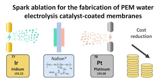
Spark Ablation for the Fabrication of PEM Water Electrolysis Catalyst-Coated Membranes

by
Foteini M. Sapountzi
1,*,
Marek Lavorenti
2,3,
Wilbert Vrijburg
4,
Sofia Dimitriadou
4,
Beata Tyburska-Pueschel
2,
Peter Thüne
5,
Hans Niemantsverdriet
1,
Tobias V. Pfeiffer
4 and
Mihalis N. Tsampas
2,*
1
Syngaschem BV, Syncat@DIFFER, 5600 HH Eindhoven, The Netherlands
2
Dutch Institute for Fundamental Energy Research (DIFFER), 5612 AJ Eindhoven, The Netherlands
3
Department of Chemical Engineering and Chemistry, Eindhoven University of Technology, 5600 MB Eindhoven, The Netherlands
4
VSPARTICLE BV, 2612 HL Delft, The Netherlands
5
Fontys University of Applied Sciences, 5612 AP Eindhoven, The Netherlands
*
Authors to whom correspondence should be addressed.
Catalysts 2022, 12(11), 1343; https://doi.org/10.3390/catal12111343
Submission received: 9 October 2022 / Revised: 30 October 2022 / Accepted: 31 October 2022 / Published: 2 November 2022

Abstract

:
Proton-exchange-membrane (PEM) electrolyzers represent a promising technology for sustainable hydrogen production, owing to their efficiency and load flexibility. However, the acidic nature of PEM demands the use of platinum-group metal-electrocatalysts. Apart from the associated high capital costs, the scarcity of Ir hinders the large-scale implementation of the technology. Since low-cost replacements for Ir are not available at present, there is an urgent need to engineer catalyst-coated membranes (CCMs) with homogeneous catalyst layers at low Ir loadings. Efforts to realize this mainly rely on the development of advanced Ir nanostructures with maximized dispersion via wet chemistry routes. This study demonstrates the potential of an alternative vapor-based process, based on spark ablation and impaction, to fabricate efficient and durable Ir- and Pt-coated membranes. Our results indicate that spark-ablation CCMs can reduce the Ir demand by up to five times compared to commercial CCMs, without a compromise in activity. The durability of spark-ablation CCMs has been investigated by applying constant and dynamic load profiles for 150 h, indicating different degradation mechanisms for each case without major pitfalls. At constant load, an initial degradation in performance was observed during the first 30 h, but a stable degradation rate of 0.05 mV h−1 was sustained during the rest of the test. The present results, together with manufacturing aspects related to simplicity, costs and environmental footprint, suggest the high potential of spark ablation having practical applications in CCM manufacturing.

Graphical Abstract

1. Introduction

It is widely accepted that hydrogen can offer a solution in the transition towards a low-carbon economy [1]. In the emerging hydrogen market, water electrolysis is expected to play a pivotal role, as it can tackle the intermittency of renewable electricity and produce large amounts of green hydrogen [2]. Various water electrolysis technologies are available, each with its own operational characteristics and advantages [3]. Among them, proton exchange membrane (PEM) electrolysis holds promise due to its efficiency, load flexibility, compact design and potential dynamic operation [4,5]. However, the acidic environment provided by the polymeric proton-conducting membrane creates a harsh operating environment, which entails the use of scarce and expensive noble metal catalysts. In general, state-of-the-art PEM electrolyzers rely on Pt-based cathodes and Ir-based anodes [6]. These rare metals represent 38% of the cost of the catalyst-coated membrane (CCM), which is the core of the stack [7].
Recently, significant progress has been made in lowering the Pt-dependence of PEM electrolyzers. According to the literature, a sufficiently high performance can be sustained either by implementing alternative electrocatalysts that are free of noble metals (e.g., Mo-based [8,9,10,11], Ag [12], CoP [13,14], FeP [14,15], and NiP2 [16]), or by decreasing the Pt loadings by a factor of ten [17]. In contrast, success stories in reducing the Ir-dependence of PEM electrolysis are lacking [18]. Only a few alternative materials have been proposed as acid-stable and low-cost oxygen evolution electrocatalysts [19,20,21,22], but their performance in realistic operating environments has not been demonstrated to date [23].
As Ir is one of the rarest elements on earth, the Ir-dependence is considered the grand challenge in PEM water electrolysis and can be a serious bottleneck in future applications of the technology. Based on a recent study [24], the up-scaling of current PEM electrolyzers (with state-of-the-art Ir loadings of 1–3 mg cm−2) at a rate of 5 GW per annum would require more than 3 t Ir per annum, which is more than half of the estimated global annual mining production. It is apparent that the realization of GW-scale PEM electrolysis requires both a >10-fold improvement in Ir utilization and the application of efficient Ir recycling processes with at least a 90% recycling rate.
Efforts to design advanced electrodes with enhanced Ir utilization have primarily focused on the development of highly structured catalysts via wet chemical routes [6]. Typical approaches to realize this focus on maximizing the Ir dispersion using high surface-area supports (e.g., doped or undoped TiO2 [6,25,26,27], TiC [28,29], TaC [29], ITO [30]) and using alternative catalyst nanostructures [31,32,33,34,35,36,37,38,39]. Hegge et al. [32] and Bernt et al. [17] have demonstrated catalyst layers with ultralow Ir loading (0.2–0.3 mg cm−2), with a similar performance to state-of-the-art CCMs.
Improved catalyst-layer manufacturing techniques using vapor-based processes [40] have been proposed as an alternative route to producing electrodes with low Ir loadings, without compromising on activity or durability. For instance, reactive spray depositionx [41], atomic layer deposition [42], and magnetron sputtering [43,44,45] have been demonstrated as successful ways to fabricate active and durable IrOx anodes with loadings as low as 0.1 mg cm−2. Moreover, vapor-based processes can ensure simplicity in manufacturing compared to the conventional multi-step and ink-based routes.
The present study demonstrates the use of an alternative vapor-based technique, based on spark ablation and impaction, for the fabrication of CCMs for PEM water electrolysis. Spark ablation is a physical process for generating clean, surfactant-free nanoparticles in a controlled manner and without the use of chemicals [46]. This method requires (semi)conductive electrodes (e.g., metal rods), an inert gas (e.g., Ar or N2), and electricity to prepare the nanoparticles at room temperature and ambient pressure. The method is described in greater detail elsewhere [46,47]. The generated nanoaerosol is subsequently accelerated through a nozzle by means of pressure difference, and inertial impaction results in adhesion of the nanoparticles to the substrate. This technology has already been successfully implemented in the manufacturing of nanoparticles or films for various applications, including as semiconductors [48] and sensors [49,50], and in high-throughput electrocatalyst screening [51], offering several advantages over conventional material-preparation techniques. Specifically, combining nanoparticle generation via spark ablation with deposition through inertial impaction enables the preparation of thin-film materials in a single step, without the need for subsequent post-processing steps. Moreover, material patterning and additive manufacturing are enabled by placing 2D substrates on an XY(Z)-stage and depositing (printing) the nanoparticle stream directly onto the substrate.
Overall, the results of the present study showcase that spark ablation can provide high-quality, thin and homogeneous catalyst layers, which can allow for an up to five-fold improvement in Ir utilization in PEM water electrolysis compared to the state-of-the-art. Durability investigations have also been carried out and demonstrated this method’s practical applicability in CCM manufacturing.

2. Results and Discussion

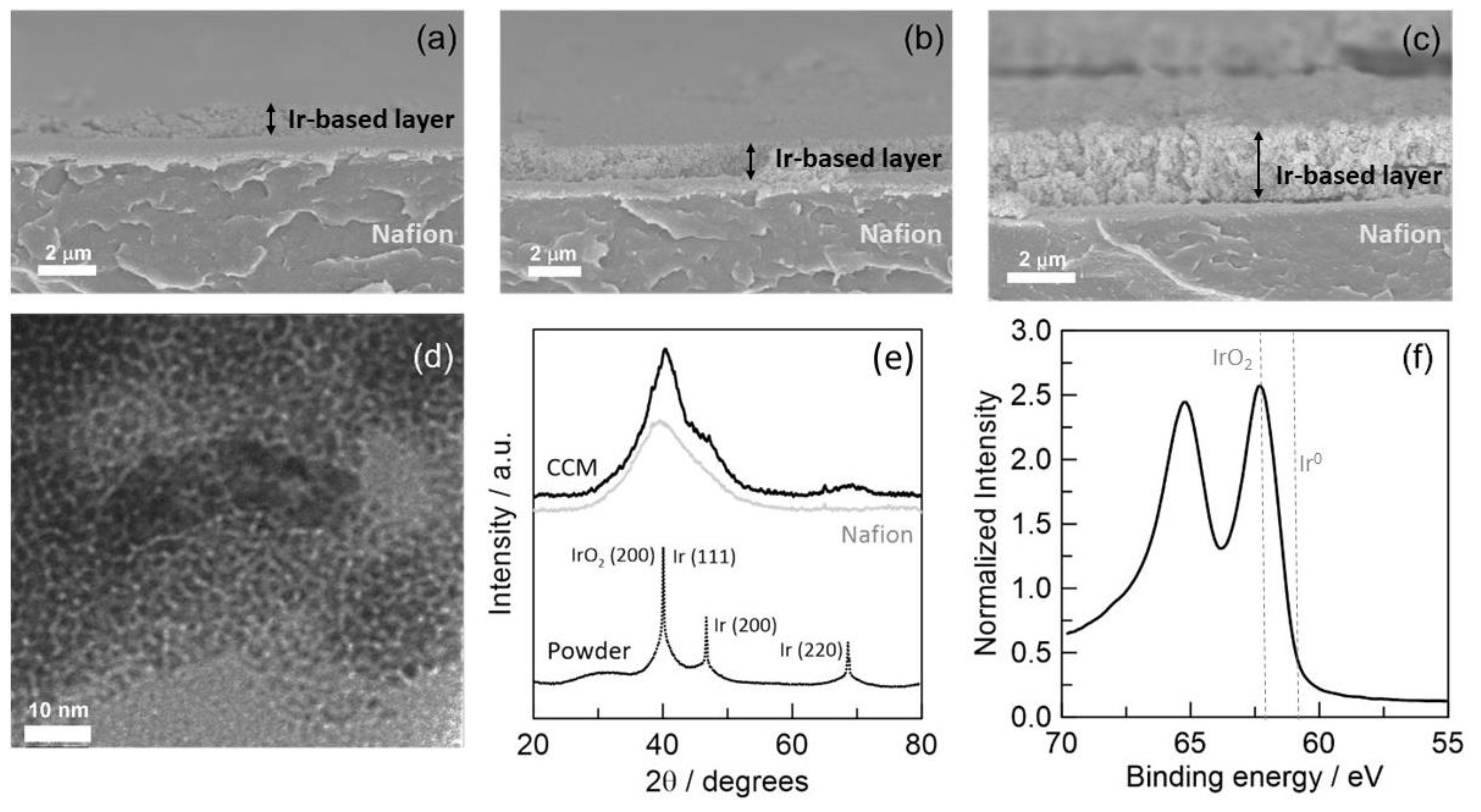
2.1. Material Characterization

Spark-ablation anode-coated CCMs comprising Ir oxide layers with different thicknesses (and thus Ir loadings) were initially fabricated with metal loadings, estimated based on deposition parameters. An RBS analysis was carried out to confirm the actual Ir loading on the spark-ablation anode-coated CCMs (Figure S1). A deviation of 3–8% between actual and predicted loadings was found, indicating the high level of control in the manufacturing procedure. Moreover, the RBS spectrum showed excellent uniformity in the depth profile of Ir and O concentrations.
The planar uniformity of the catalyst layers at the spark-ablation CCMs was verified via cryo-fractured cross-section SEM images (Figure 1a–c). CCMs with an Ir loading of 0.8 and 1.2 mg cm−2 consist of uniform and dense, yet porous, IrOx layers with 1.2 µm and 2.1 µm thicknesses, respectively (Figure 1b,c), suggesting a layer porosity of ~50%. The morphology of the CCM with a 0.4 mg cm−2 Ir loading was different (Figure 1a), consisting of a thin layer (~0.7 µm thick) and thicker clots (~1.1 µm thick). TEM characterization indicated that the IrOx nanoparticles have a mean particle size of 2 nm (Figure 1d), which is smaller than the sizes typically reported for systems prepared with conventional wet chemistry methods (e.g., Adam’s fusion, colloidal deposition) [52], and smaller than the nanoparticle size of the commercial CCM (Figure S2).
The observed wide peak at the 2θ range of 32–50° in the XRD pattern (Figure 1e) appears to correspond to the Nafion 115 membrane, with broad contributions from Ir or IrOx reflections. XRD pattern of the catalyst collected from deposition chamber is also provided for comparison, while indexing of the peaks is based on JCPDS card no 6598 and 15,870 for Ir and IrO2 respectively. XPS analysis shows two peaks in the Ir 4f spectrum (Figure 1f) positioned at 62.3 eV and 65.2 eV, and indicates the presence of iridium oxide [53]. Combined with XRD data, we speculate that the Ir layer is passivated after sample preparation and readily oxidizes to form small IrOx nanoparticles. The oxidation may take place during the nanoparticle generation due to the presence of trace amounts of oxygen in the Ar carrier gas.

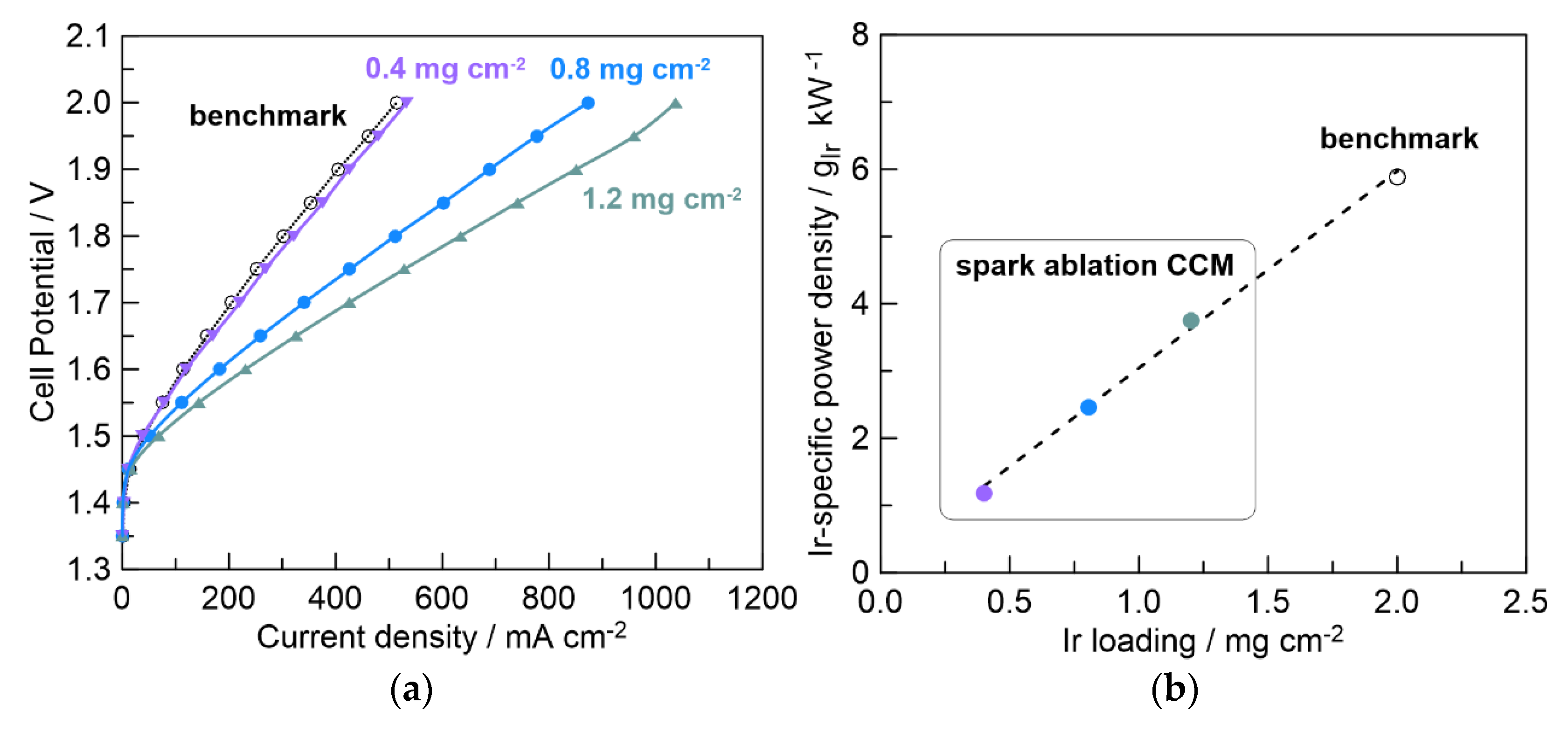
2.2. Electrocatalytic Activity of Spark-Ablation Anode-Coated CCMs

Figure 2a shows the polarization curves during PEM water electrolysis at 60 °C, obtained with CCMs fabricated via spark ablation and with the commercial (benchmark, 2 mg IrRuOx cm−2) CCM. It is clearly shown that the spark-ablation CCMs outperform the benchmark, despite containing 20–80% less iridium. This is believed to mainly be related to their very small nanoparticle size compared to commercial CCM. Small nanoparticles allow for efficient Ir utilization without the need for the addition of a Nafion ionomer to the catalyst layer, which could, in turn, minimize mass transport losses.
In general, the improvement in Ir utilization can be experimentally visualized either by achieving an increase in current density using commercial Ir loading or by achieving state-of-the-art current density using less Ir loading. To establish a solid basis for comparison, the Ir-specific power density (measured in gIr kW−1) is the most typically used descriptor for Ir utilization. Low values are desired for this parameter, indicating that less Ir is needed to drive 1 kW electrolysis. As shown in Figure 2b, spark-ablation CCMs managed to exhibit up to a five-fold decrease in the Ir-specific power density compared to the benchmark CCM. This finding suggests that further reduction of the loading could lead to better material utilization, however physicochemical characterization has identified the 0.4 mg cm−2 loading is the minimum threshold for obtaining uniform catalyst layers (with the current deposition parameters). We have realistic expectations (on-going work) that this limitation can be by-passed by utilizing alternative deposition parameters or by depositing the catalyst layers on porous transport layers.
According to the most recent assessment of the Ir demand model, upscaling PEM water electrolysis at GW levels can be only achieved by reducing the Ir-specific power density by an order of magnitude [24]. The data presented here demonstrate the potential of the nanoparticle-printing manufacturing technique to allow for a significant reduction in Ir loadings. However, the overall cell performance, as presented in Figure 2a, should not be quantitatively compared to the state-of-the-art technical assumptions of the published Ir demand model (0.67 gIr kW−1 in 2020) [24]. There are several reasons for this deviation in performance. First, the assumed state-of-the-art performance data correspond to the electrolysis performed with thin Nafion membranes (Nafion 212) at 80 °C, whereas the present study utilizes thicker Nafion membranes (Nafion 115), and experiments were carried out at 60 °C (the technical limitations of the experimental setup did not allow for measurements at higher temperatures). Second, as recently reported by Bender et al. [54], the literature data on PEM electrolysis show large fluctuations between different laboratories, with up to 0.5 V potential deviations (at 1 A cm−2 with Nafion 115 at 80 °C). The authors of this study [54] attribute this deviation to variations in the specifications of the cell components, cell pre-conditioning, experimental protocols, operating conditions, and/or equipment framework. Third, our cathodes consisted of Pt-based gas-diffusion electrodes, which were mechanically attached to the opposite side of the Ir-coated Nafion membrane and pressed within the cell hardware, without any ionomer-coating or hot-pressing.

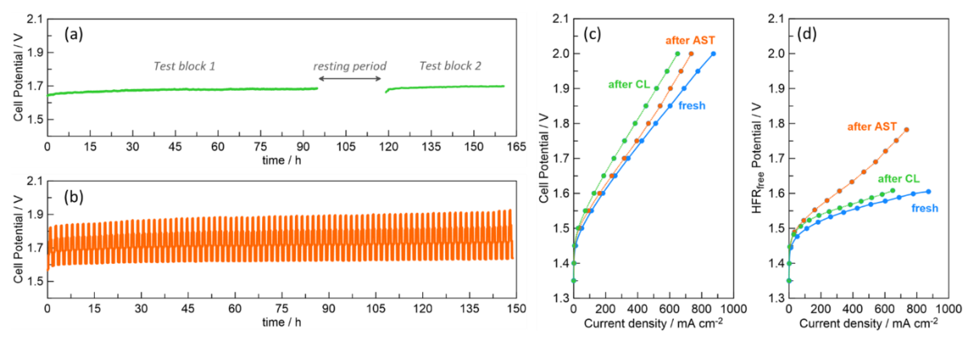
2.3. Durability of Spark-Ablation Anode-Coated CCMs

Complete performance assessment of CCMs should not only rely on activity investigations, but also on durability investigations [55]. To simulate both transient and dynamic service conditions, different time profiles were used for the power input. The spark-ablation CCMs with an Ir loading of 0.8 mg cm−2 were used for the durability tests, as an optimal case for Ir utilization, activity and homogeneity in morphology.
Figure 3a depicts the CCM’s ability to sustain its activity during prolonged operation at a constant load (CL) of 200 mA cm−2 in two test blocks. The first test block can be divided into three stages. During the first 15 h, an initial sharp potential increase (1.6 mV h−1) was observed. A second 15 h stage followed this (t: 15–30 h), where the degradation rate was much lower (0.5 mV h−1). Within the third state (t: 30–95 h), a stable degradation rate of 0.05 mV h−1 was maintained for over 60 h. This is in line with the degradation rates reported in the literature, which typically span between 0 and 0.2 mV h−1 [56].
The profile during the second test block shows a uniform degradation rate, which is equal to the one obtained in the third (final) stage of the first testing block. The overall profile of the CL test indicates that irreversible changes occurred at the CCM during the first 30 h at constant polarization, while, afterwards, a stable degradation rate of 0.05 mV h−1 was sustained. These irreversible changes were also observed as a potential 22 mV increase between the first and second test block of CL. However, as discussed below, these changes had a negligible role in the overall CCM degradation. The CL profile of the benchmark CCM (Figure S3) showed a lower degradation rate of 0.01 mV h−1, which was stable throughout the whole duration of the first and second test blocks.
PEM water electrolyzers typically operate in the potential range of 1.8–2.2 V [2]. Assuming that the 0.05 mV h−1 degradation rate remains unchanged, and assuming a cut-off cell potential of 2.2 V, the expected lifetime of the spark-ablation CCM is 10,000 h, which is the minimum duration of industrial operation. The stability factor was proposed by Siracusano et al. [57] as an additional durability descriptor. This descriptor does not depend on the cut-off potential, which can vary among the various electrolyzer manufacturers, and also considers the initial cell potential. Based on the CL profile of Figure 3a, the stability factor for the spark-ablation CCM is 1.2 × 10⁵ h V−2, which is lower than the value of 4.0 × 10⁵ h V−2 reported for a CCM with similarly low Ir loadings [57].
The response of the spark-ablation CCM to a dynamic current profile (AST profile, Figure 3b and Figure S4) shows a potential increase at both the upper limit (90 mV increase) and lower limit (50 mV increase, whereas the potential amplitude remained almost unchanged). Figure 3c shows the polarization plots obtained before and after the CL and AST time profiles. Since the stress was monitored during cell assembly, and the CCM did not experience any sudden temperature and humidity gradients, it is believed that the observed changes in polarization curves are only related to the structural and chemical changes imposed by the CL and AST time profiles. Overall, an up to 100 mV potential increase was observed in the polarization curve after the CL profile, while the potential increase was lower (70 mV) after the AST profile. EIS measurements before and after the durability tests (Figure S5) indicated an increase in the high-frequency resistance (HFR) after the CL profile and a decrease after the AST profile. Therefore, it appears that the source of degradation is different for the two durability profiles.
At a current density of 0.6 mA cm−2 the ohmic losses correspond to 55.5% of the cell overpotential for the fresh CCM and 64% after the CL profile. Considering the literature data for the conductivity of fully humidified Nafion 115 membranes at 60 °C [58], and the resistance measurements of the cell hardware used in this study, it appears that the interfacial ohmic losses increased from 1% to 13% of the total cell overpotential. The HFR-free potential, however, remained almost unchanged (Figure 3d). Specifically, only a minor increase (almost 20 mV) was observed in the HFR-free potential after the CL profile. It thus appears that the increase in ohmic interfacial losses almost fully accounts for the CCM performance degradation that occurs after CL.
However, the ohmic resistance trend after the AST profile is different than that for the CL profile. A decrease in ohmic resistance was observed after AST, in agreement with trends reported in the literature during the first 170–340 h of dynamic durability studies [56,58]. This decrease is possibly related to the improved mass transport of oxygen bubbles through the catalyst layer [59]. The large increase in the HFR-free potential after the AST profile suggests that the performance degradation after AST is related to chemical or structural changes in the catalyst layer, resulting in a decrease in the electrochemical active surface area or deterioration in intrinsic activity [55]. Such phenomena are possibly related to either Ir dissolution, which is known to be more profound in hydrous IrOx [60], or to IrOx crystallization, which is known to be less active for oxygen evolution than the hydrous (amorphous) IrOx [60].

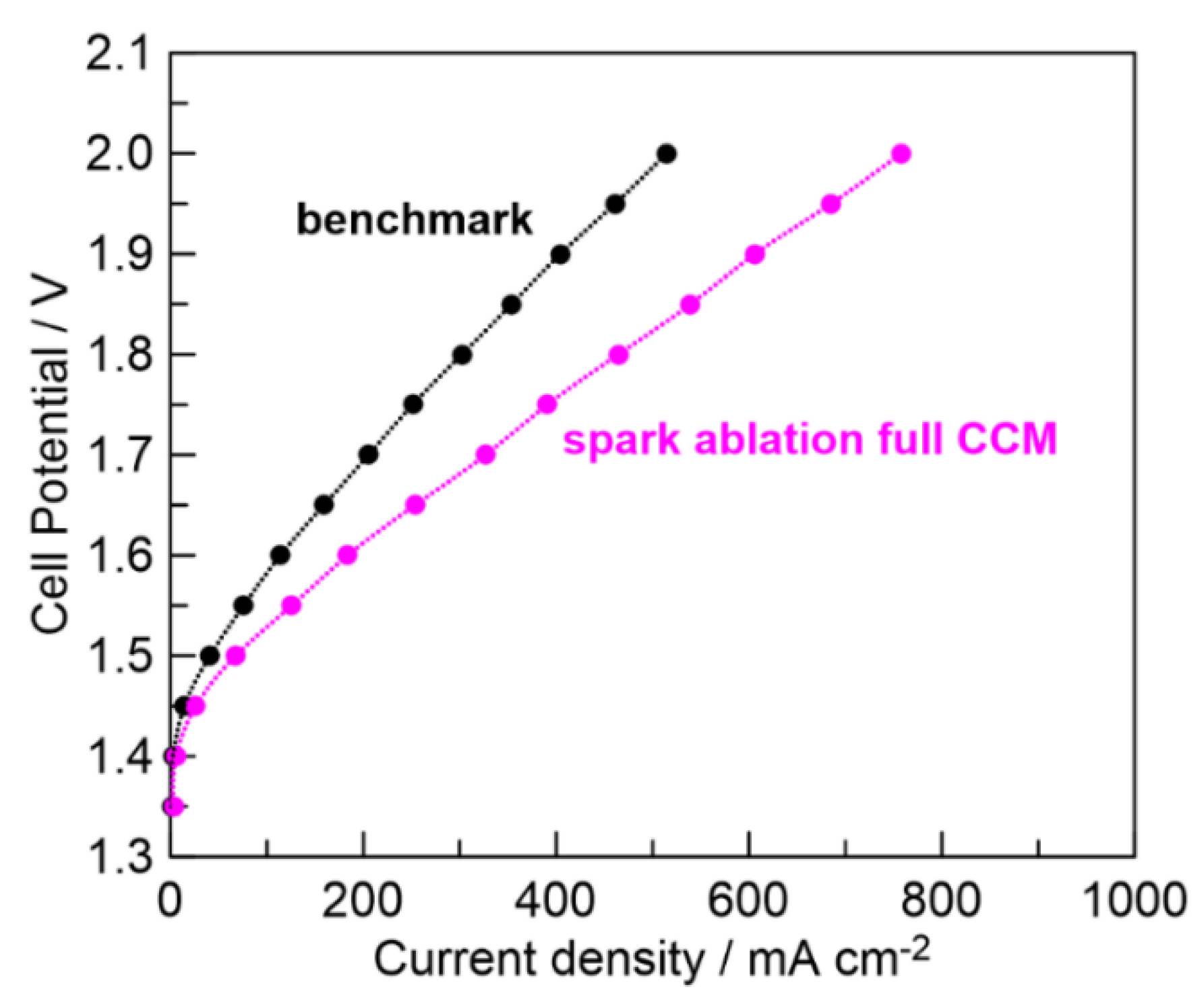
2.4. Performance of Full CCMs Fabricated with Spark Ablation

To be of practical interest, the spark-ablation-based fabrication technique should be also able to produce full CCMs, coated at both sides, where both anode and cathode catalyst layers present a sufficient performance and none of the catalyst layers are mechanically damaged during deposition. As a proof-of-concept to address this issue, a full CCM was fabricated via spark ablation. For the anode side, a loading of 0.8 mg cm−2 Ir was used, which was optimal according to the findings with anode-coated spark-ablation CCMs. For the cathode, a 0.6 µm thick Pt film with 0.5 mg cm−2 loading was deposited at the opposite side of the Nafion membrane. The results of the physicochemical characterization of the Pt film can be found in Figure S6.
The spark-ablation full CCM was evaluated during PEM water electrolysis at 60 °C and, as shown in Figure 4, outperformed the benchmark. Specifically, the spark-ablation full CCM reduced the potential demands for electrolysis by up to 160 mV, even though the total platinum group metal content (anode and cathode) at the spark-ablation full CCM was more than four times lower compared to the benchmark CCM. Its CL durability profile (Figure S7) showed no major signs of degradation, but the durability indicators (degradation rate of 0.103 mV h−1, stability factor of 0.06 × 10⁵ h V−2) suggest that tailoring of the deposition parameters is required to enable further optimization.

2.5. Other Practical Considerations

Apart from achieving improved Ir utilization, spark ablation can relieve the high CCM manufacturing costs, which currently account for 42% of the total CCM costs [7]. Conventional methods for the fabrication of catalyst layers on ion-conducting polymeric membranes involve several processing steps [61], which are related to the synthesis of the powder catalyst, the preparation of a catalyst ink (containing the catalyst, an ionomer and/or a binding agent and specific solvents), the application of the ink (e.g., spray-coating, screen or inkjet printing) and drying of the catalyst layer (Figure 5, left).
Using spark ablation and impaction, catalyst nanoparticles can be formed and printed onto the proton-exchange membranes using a single-step process (Figure 5, right). This leads the overall proposed process to be faster, simpler (less equipment, manpower and quality control units) and more environmentally friendly (since the use of liquid chemicals is eliminated) compared to the conventional methods of catalyst synthesis.

3. Materials and Methods

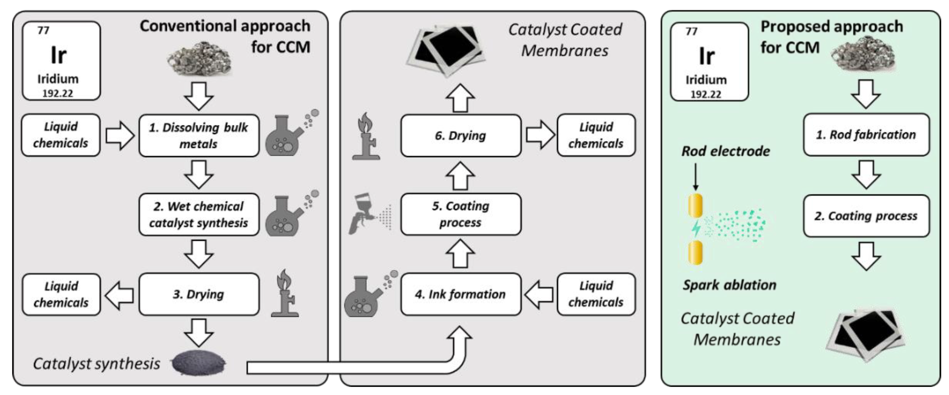
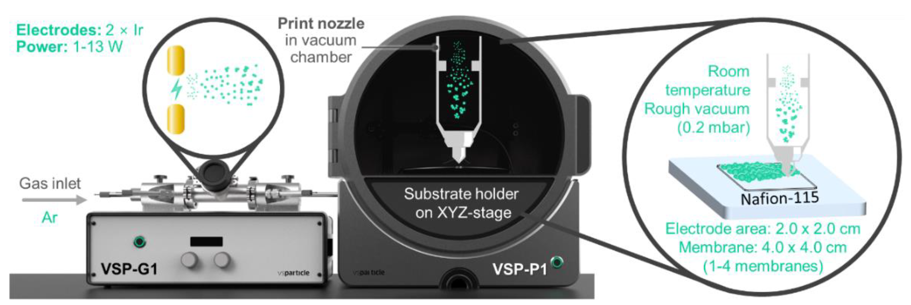
3.1. Fabrication of Catalyst-Coated Membranes (CCMs) with Spark Ablation

Two types of CCMs were fabricated using spark ablation: anode-coated CCMs comprising Ir oxide layers with Ir loadings controlled between 0.4 and 2.4 mg cm−2, and full CCMs (i.e., double-sided) prepared via spark ablation, comprising an IrOx layer with 0.8 mg cm−2 Ir at the anode and a 0.5 mg cm−2 Pt layer at the cathode. Nafion 115 ((C7HF13O5S C2F4)x) with a thickness of 127 µm (purchased from FuelCellsEtc) was chosen as the proton exchange membrane, to allow for the final CCMs to have better mechanical strength and lower gas crossover compared to thinner membranes. IrOx and Pt coatings were applied to the Nafion membranes by means of a VSP-P1 Nanoprinter (VSPARTICLE) equipped with a VSP-G1 Nanoparticle Generator (VSPARTICLE, Figure 6 and Figure S8). In general, Ir nanoparticles were generated using the VSP-G1 equipped with Ir electrodes (2 mm diameter, 99% Ir, Chempur, Karlsruhe, Germany), employing a total power of 13 W (1.3 kV, 10.0 mA) and Ar as an inert carrier gas (99.999%, 2 L/min). Similarly, Pt nanoparticles were generated using the VSP-G1 equipped with Pt electrodes (3 mm diameter, 99.9% Pt, Chempur), and employing a total power of 13 W (1.3 kV, 10.0 mA) and Ar as inert carrier gas (2 L/min). After the nanoparticle generation, deposition onto the substrate (Nafion 115) took place directly via inertial impaction, using the VSP-P1 Nanoprinter. This was achieved by accelerating the nanoparticle aerosol through a nozzle directed at the substrate. The pressure difference introduced by keeping the substrate under rough vacuum (~1 mbar) is the driving force that accelerates the nanoaerosol through the nozzle, leading to the formation of IrOx and Pt layers on the Nafion membrane. Inertial impaction results in adhesion of the nanoparticles to the Nafion without requiring a binder, preserving the purity/cleanliness of the particles. By securing the substrate on an XY(Z)-stage, the nanoparticles were efficiently patterned onto the Nafion substrate. IrOx and Pt catalyst layers of 2 × 2 cm2 were obtained by depositing 100 parallel lines of 20 mm in length. Catalyst loadings were controlled by varying the printing speed between 30 and 200 µm/s, with slower print speeds yielding higher loadings.

3.2. Physicochemical Characterization

Scanning electron microscopy (SEM) was conducted with a FEI Sirion Field Emission Gun microscope. The secondary electron images of the surfaces of the catalyst layers were made at an accelerating voltage of 5 kV. For the cryo-fractured cross-sections, the samples were immersed in liquid nitrogen and broken. The Back-Scattered Electron images of the cross-sections were recorded with an acceleration voltage of 10 kV. Transmission electron microscopy (TEM) was conducted with an FEI Cryo-Transmission Electron Microscope TITAN 300 kV. The catalyst-coated membrane was placed in a solution of ethanol and sonicated for 30 min. The TEM grid was placed on Whatman paper and the ethanol solution with the nanoparticles (10 mL) was drop-casted on this with a micropipette. The TEM grid was dried at room temperature and then was ready for imaging in the TEM. X-ray Diffraction (XRD) was employed to investigate the crystal structure and crystallinity of the catalyst layer. XRD patterns were obtained using a Bruker D8 Advance ECO XRD with a Cu Kα radiation (λ = 1.5405 Å) at 40 kV and 25 mA. The 2θ angles were measured between 20° and 80° with a step size of 0.03° and measuring time of 19 s per step. X-ray photoelectron spectroscopy (XPS) was used to analyze the chemical composition of the catalyst layers and surface oxidation of the Ir. XPS was performed using a K-Alpha with Thermo Scientific, equipped with a detector at normal incidence. The composition of the top surface was studied in a vacuum environment of 1 × 10⁻⁸ mbar, where the monochromatic Al-Kα radiation was used. Spectra were obtained in the Ir 4f and O 1 s regions. XPS sensitivity factors from the Scofield library [58] were used for quantification.

3.3. Catalyst Loading

The target catalyst loadings were obtained by setting a deposition time for a calibrated deposition rate of 0.5 mg h−1. To confirm the actual Ir and O loadings and depth profiles in the Ir layers, Rutherford Backscattering (RBS) measurements were performed with a 2.4 MeV 4He beam perpendicular to the sample surface (α = 0⁰). Some films were measured at two different locations to determine the film’s uniformity. The 25 mm2-area passivated, implanted, planar, silicon (PIPS) detector (solid angle Ω = 0.874 msr, no foil, 15 keV resolution) was located at a scattering angle of 170°. Small beams (0.5 mm × 0.5 mm) and low currents (10–15 nA) were used to minimize the film damage caused by the He-beam. All the samples were measured at the same charge of 2 µC. The elemental loading and depth profiles were determined by simulation, performed using SIMNRA (version 7.03, Garching, Germany). Poisson noise, statistical errors, current measurements and simulation uncertainties contribute to the error bar. The depth profiles are shown as elemental concentration in at.% versus depth in thin film units (TFU). One TFU corresponds to 1 atomic layer.

3.4. Fabrication of Final Membrane Electrode Assemblies

The spark-ablation anode-coated CCMs were interfaced to commercial Pt gas diffusion electrodes (Pt-C on Carbon Cloth, 4 mg Pt cm−2, purchased from FuelCellsEtc). To ensure that the obtained differences in electrochemical performance are only related to the Ir catalyst layers, and to minimize the number of processing steps, the Pt cathodes were simply mechanically attached to the anode-coated CCMs, without hot-pressing. A benchmark anode-coated CCM (2 mg IrRuOx cm−2/Nafion 115, FuelCellsEtc) served as the reference baseline for these studies. The spark-ablation full-CCM (both anode and cathode catalyst layers deposited by spark ablation and the printing of nanoparticles) was used as prepared. In all cases, a platinized Ti mesh (FuelCellsEtc) was used for anode current collection.

3.5. Polarization Measurements

The membrane electrode assemblies were loaded to an in-house-built 4 cm2 PEM electrolysis single cell, equipped with Ti-bipolar plates. The operating temperature was monitored using a K-type thermocouple and was controlled with an Omega CN16DPT-144-EIP temperature controller. Deionized water was supplied to both anodic and cathodic compartments with a flowrate of 10 mL min−1, using a dual-channel peristaltic pump (Masterflex, Gelsenkirchen, Germany, C/L). Electrochemical data were collected using a Vertex.10A.EIS potentiostat/galvanostat (Ivium Technologies, Eindhoven, The Netherlands). Polarization curves were recorded at 60 °C by holding constant potential steps of 3 min duration.

3.6. Durability Assessment

Studies focused on the stability and durability were performed at 60 °C using CCMs with Ir loading of 0.8 mg cm−2. The durability studies were carried out at the same single-cell setup used for the polarization measurements. Two different protocols were followed, based on the EU Harmonized Protocols for testing low-temperature water electrolyzers [62]. To investigate the ability of the CCM to withstand constant service loads (CL), the system was operated in the galvanostatic mode (200 mA cm−2). The voltage increase rate was experimentally determined by monitoring the cell potential in two test blocks, with durations of 95 h and 42 h, respectively, interspersed with a rest period of 23 h. The accelerated stress test (AST) was carried out to simulate end-applications with frequent periods of variable power input. The protocol was based on 85 sequential cycles of ramp-up and ramp-down profile, where the duration of each galvanostatic step is 15 min and the ramp rate is (imax*0.2), where imax is the maximum design test current (chosen as 400 mA cm−2 for our experiments). Therefore, the overall duration of the AST was 150 h. Polarization curves were measured before and after each durability test.

4. Conclusions

This study demonstrates a new vapor-phase manufacturing method for catalyst-coated membranes (CCMs) for PEM water electrolysis. The deposition technique is based on spark ablation and impaction, and allows for the fabrication of homogeneous catalyst layers on Nafion membranes, even at low Ir and Pt loadings. Moreover, this technique offers a series of advantages with practical importance, such as simplicity, reduced cost and a reduced environmental footprint, compared to conventional manufacturing approaches.
Anode-coated CCMs with 20–80% less noble-metal loading compared to the state-of-the-art were tested during water electrolysis in a 4 cm2 single cell. The spark-ablation CCMs outperformed the commercial CCM, exhibiting up to a five-fold decrease in the Ir-specific power density compared to a commercial CCM. Constant and dynamic load profiles of 150 h duration were applied to the anode-coated CCMs to investigate their durability, and no major degradation was observed. Our results indicate that different degradation mechanisms apply for each durability profile. At a constant load, a relatively abrupt potential increase (>1 mV h−1) was observed during the first 30 h, where irreversible changes occurred. During the rest of the test, a stable degradation rate of 0.05 mV h−1 was sustained. Post-polarization data showed that the constant load profile led to increased interfacial ohmic losses, which affected the performance of the CCM. This, however, was not the case for the dynamic load profile, where our results suggest that chemical or structural changes occurred at the catalyst and affected kinetics.
A full CCM with IrOx anode and Pt cathode was also fabricated using spark ablation as a proof-of-concept to demonstrate the technique’s potential to fabricate CCMs that were coated at both sides. At 2 V, the full CCM reached a current density that was >1.5 times higher than a commercial CCM, while it showed a decrease in the overall loading of noble metals by four times. The fully coated CCM showed no major signs of degradation upon 150 h operation at a constant load. However, the relatively large potential increase rate of 0.103 mV h−1 indicates that further adjustments are required in the deposition protocols to enable optimization and meet the industrial durability requirements.
Overall, the experimental findings of this study provide evidence that spark ablation can reduce the currently high cost of CCMs for PEM electrolysis at two levels. First, this allows for significant reductions in the amounts of expensive and scarce electrocatalysts (which account for 38% of the CCM cost [7]). It is clear that there is still room for performance improvements, and future research should focus on tuning the deposition parameters and the membrane electrode assemblies architecture to reach even lower loadings. Second, due to its simplicity and single-step nature, it has the potential to decrease manufacturing costs (which account for 42% of the CCM cost [7]).

Supplementary Materials

The following supporting information can be downloaded at: https://www.mdpi.com/article/10.3390/catal12111343/s1. Figure S1: (a) RBS raw data (black line) and simulation data (red line) for anode-coated spark-ablation CCM. The estimated actual Ir loading of 0.77 mg cm−2 ± 3.5% is in excellent agreement with the nominal (predicted) loading of 0.8 mg cm−2. (b) Elemental concentration in at% for C, O, F, Ir (C, F are attributed to the Nafion membrane; Ir and O to the catalyst layer) versus the film thickness in thin-film units (tfu). The IrOx film has a thickness of 8800 tfu. Figure S2: TEM images at 400 k magnification of IrOx-coated Nafion CCMs. Left: commercial CCM; typical grains with diameter of 10 nm are observed. Right: spark-ablation CCM; typical grains with 2 nm diameter are observed. Figure S3: Time evolution of cell potential during two test blocks of constant-load (CL) operation at 200 mA cm−2 at 60 °C with a commercial (benchmark) CCM. A 2 mg IrRuOx cm−2 coated Nafion 115 interfaced with a Pt/C-cloth (4 mg cm−2). Figure S4. The testing block followed an accelerated stress test (AST). The AST profile consists of successively performing this testing block 85 times. Figure S5: Nyquist spectra before and after (a) the constant-load (CL) durability profile, (b) the accelerated stress test (AST) durability profile. IrOx-coated spark-ablation CCM (0.8 mg cm−2), Nafion 115, 4 mg Pt cm−2 on C-cloth cathode. Figure S6: Physicochemical characterization of the Pt film, which served as a cathode for the spark-ablation full-CCM study. (a) Cryo-fractured SEM cross-section showing the uniformity and thickness of the Pt layer, (b) XRD pattern of Pt/Nafion side, (c) XPS Pt 4f spectrum. Figure S7: Time evolution of cell potential during two test blocks of constant-load (CL) operation at 200 mA cm−2 at 60 °C, with a spark-ablation fully coated CCM (0.8 mg IrOx cm−2, 0.5 mg Pt cm−2, Nafion 115). Figure S8: Process flow of nanoparticle generation via spark ablation and printing via impaction.

Author Contributions

Conceptualization, F.M.S., M.L. and M.N.T.; methodology, W.V., S.D., T.V.P., F.M.S. and M.L.; validation, F.M.S., M.L. and S.D.; formal analysis, F.M.S., M.L. and W.V.; investigation, F.M.S. and M.L.; resources, M.N.T., P.T., T.V.P. and H.N.; data curation, F.M.S., B.T.-P. and M.L.; writing—original draft preparation, F.M.S. and M.L.; writing—review and editing, M.N.T., W.V., H.N. and P.T.; supervision, M.N.T.; funding acquisition, M.N.T., H.N., T.V.P. and P.T. All authors have read and agreed to the published version of the manuscript.

Funding

This work was financially supported by Regieorgaan SiA through the RAAK.PRO03.122 project Energy and Climate subsidy. Syngaschem BV acknowledges substantial discretional funding from Synfuels China Technology (Beijing, China).

Data Availability Statement

The data that support the findings of this study are openly available in Zenodo at https://doi.org/10.5281/zenodo.7265439 (accessed on 30 October 2022).

Acknowledgments

G. Zafeiropoulos, I. van den Heuvel, P. Tils, K. Buiter and T. Peeters are acknowledged for their experimental support in the electrochemical measurements, E. Zoethout from DIFFER for his assistance with TEM, XRD and XPS analysis, C. van Roost and N. Dewit, both from the microscopy lab of Agfa-Gevaert N.V, for the SEM analysis.

Conflicts of Interest

The authors declare no conflict of interest.

References

  1. Taibi, E.; Miranda, R.; Vanhoudt, W.; Winkel, T.; Lanoix, J.-C.; Barth, F. Hydrogen from Renewable Power: Technology Outlook for the Energy Transition; International Renewable Energy Agency: Abu Dhabi, United Arab Emirates, 2018. [Google Scholar]
  2. Schmidt, O.; Gambhir, A.; Staffell, I.; Hawkes, A.; Nelson, J.; Few, S. Future cost and performance of water electrolysis: An expert elicitation study. Int. J. Hydrogen Energy 2017, 42, 30470–30492. [Google Scholar] [CrossRef]
  3. Sapountzi, F.M.; Gracia, J.M.; Weststrate, C.J.; Fredriksson, H.O.A.; Niemantsverdriet, J.W. Electrocatalysts for the generation of hydrogen, oxygen and synthesis gas. Prog. Energy Combust. Sci. 2017, 58, 1–35. [Google Scholar] [CrossRef] [Green Version]
  4. Babic, U.; Suermann, M.; Büchi, F.N.; Gubler, L.; Schmidt, T.J. Critical REVIEW—Identifying Critical gaps for polymer electrolyte water electrolysis development. J. Electrochem. Soc. 2017, 164, F387–F399. [Google Scholar] [CrossRef] [Green Version]
  5. Shiva Kumar, S.; Himabindu, V. Hydrogen production by PEM water electrolysis—A review. Mater. Sci. Energy Technol. 2019, 2, 442–454. [Google Scholar] [CrossRef]
  6. Bernt, M.; Hartig-Weiß, A.; Tovini, M.F.; El-Sayed, H.A.; Schramm, C.; Schröter, J.; Gebauer, C.; Gasteiger, H.A. Current challenges in catalyst development for PEM water electrolyzers. Chemie Ingenieur Technik 2020, 92, 31–39. [Google Scholar] [CrossRef] [Green Version]
  7. International Renewable Energy Agency. Green Hydrogen Cost Reduction Scaling Up Electrolysers to Meet The 1.5°C Climate Goal; International Renewable Energy Agency: Abu Dhabi, United Arab Emirates, 2020. [Google Scholar]
  8. Holzapfel, P.K.R.; Bühler, M.; Escalera-López, D.; Bierling, M.; Speck, F.D.; Mayrhofer, K.J.J.; Cherevko, S.; Pham, C.V.; Thiele, S. Fabrication of a robust PEM water electrolyzer based on non-noble metal cathode catalyst: [Mo3S13]2− clusters anchored to n-doped carbon nanotubes. Small 2020, 16, 2003161. [Google Scholar] [CrossRef]
  9. Ng, J.W.D.; Hellstern, T.R.; Kibsgaard, J.; Hinckley, A.C.; Benck, J.D.; Jaramillo, T.F. Polymer electrolyte membrane electrolyzers utilizing non-precious mo-based hydrogen evolution catalysts. ChemSusChem 2015, 8, 3512–3519. [Google Scholar] [CrossRef]
  10. Sarno, M.; Ponticorvo, E. High hydrogen production rate on RuS2@MoS2 hybrid nanocatalyst by PEM electrolysis. Int. J. Hydrogen Energy 2019, 44, 4398–4405. [Google Scholar] [CrossRef]
  11. Morozan, A.; Johnson, H.; Roiron, C.; Genay, G.; Aldakov, D.; Ghedjatti, A.; Nguyen, C.T.; Tran, P.D.; Kinge, S.; Artero, V. Nonprecious bimetallic iron–molybdenum sulfide electrocatalysts for the hydrogen evolution reaction in proton exchange membrane electrolyzers. ACS Catal. 2020, 10, 14336–14348. [Google Scholar] [CrossRef]
  12. Mo, J.; Stefanov, B.I.; Lau, T.H.M.; Chen, T.; Wu, S.; Wang, Z.; Gong, X.Q.; Wilkinson, I.; Schmid, G.; Tsang, S.C.E. Superior performance of Ag over Pt for hydrogen evolution reaction in water electrolysis under high overpotentials. ACS Appl. Energy Mater. 2019, 2, 1221–1228. [Google Scholar] [CrossRef]
  13. King, L.A.; Hubert, M.A.; Capuano, C.; Manco, J.; Danilovic, N.; Valle, E.; Hellstern, T.R.; Ayers, K.; Jaramillo, T.F. A non-precious metal hydrogen catalyst in a commercial polymer electrolyte membrane electrolyser. Nat. Nanotechnol. 2019, 14, 1071–1074. [Google Scholar] [CrossRef] [PubMed]
  14. Brito, J.; Restivo, J.; Sousa, J.P.S.; Spera, N.C.M.; Falcão, D.S.; Rocha, A.; Pinto, A.M.F.R.; Pereira, M.F.R.; Soares, O.S.G.P.; Sadykov, A.; et al. Implementation of transition metal phosphides as Pt-free catalysts for PEM water electrolysis. Energies 2022, 15, 1821. [Google Scholar] [CrossRef]
  15. Sapountzi, F.M.; Orlova, E.D.; Sousa, J.P.S.; Salonen, L.M.; Lebedev, O.I.; Zafeiropoulos, G.; Tsampas, M.N.; Niemantsverdriet, H.J.W.; Kolen’ko, Y.V. FeP Nanocatalyst with Preferential [010] Orientation Boosts the Hydrogen Evolution Reaction in Polymer-Electrolyte Membrane Electrolyzer. Energy Fuels 2020, 34, 6423–6429. [Google Scholar] [CrossRef]
  16. Owens-Baird, B.; Xu, J.; Petrovykh, D.Y.; Bondarchuk, O.; Ziouani, Y.; González-Ballesteros, N.; Yox, P.; Sapountzi, F.M.; Niemantsverdriet, H.; Kolen’ko, Y.V.; et al. NiP2: A story of two divergent polymorphic multifunctional materials. Chem. Mater. 2019, 31, 3407–3418. [Google Scholar] [CrossRef]
  17. Bernt, M.; Siebel, A.; Gasteiger, H.A. Analysis of voltage losses in PEM water electrolyzers with low platinum group metal loadings. J. Electrochem. Soc. 2018, 165, F305–F314. [Google Scholar] [CrossRef]
  18. Li, L.; Wang, P.; Shao, Q.; Huang, X. Recent progress in advanced electrocatalyst design for acidic oxygen evolution reaction. Adv. Mater. 2021, 33, 2004243. [Google Scholar] [CrossRef]
  19. Barrios Jimenez, A.M.; Burkhardt, U.; Cardoso-Gil, R.; Höfer, K.; Altendorf, S.G.; Schlögl, R.; Grin, Y.; Antonyshyn, I. HF2B2IR5: A self-optimizing catalyst for the oxygen evolution reaction. ACS Appl. Energy Mater. 2020, 3, 11042–11052. [Google Scholar] [CrossRef]
  20. Evans, T.A.; Choi, K.S. Electrochemical synthesis and investigation of stoichiometric, phase—Pure CoSb2O6 and MnSb2O6 electrodes for the oxygen evolution reaction in acidic media. ACS Appl. Energy Mater. 2020, 3, 5563–5571. [Google Scholar] [CrossRef]
  21. Yang, L.; Yu, G.; Ai, X.; Yan, W.; Duan, H.; Chen, W.; Li, X.; Wang, T.; Zhang, C.; Huang, X.; et al. Efficient oxygen evolution electrocatalysis in acid by a perovskite with face-sharing IrO6 octahedral dimers. Nat. Commun. 2018, 9, 5236. [Google Scholar] [CrossRef] [Green Version]
  22. Lemoine, K.; Gohari-Bajestani, Z.; Moury, R.; Terry, A.; Guiet, A.; Grenèche, J.M.; Hémon-Ribaud, A.; Heidary, N.; Maisonneuve, V.; Kornienko, N.; et al. Amorphous iron-manganese oxyfluorides, promising catalysts for oxygen evolution reaction under acidic media. ACS Appl. Energy Mater. 2021, 4, 1173–1181. [Google Scholar] [CrossRef]
  23. Sun, X.; Xu, K.; Fleischer, C.; Liu, X.; Grandcolas, M.; Strandbakke, R.; Bjørheim, T.; Norby, T.; Chatzitakis, A. Earth-abundant electrocatalysts in proton exchange membrane electrolyzers. Catalysts 2018, 8, 657. [Google Scholar] [CrossRef] [Green Version]
  24. Minke, C.; Suermann, M.; Bensmann, B.; Hanke-Rauschenbach, R. Is iridium demand a potential bottleneck in the realization of large-scale PEM water electrolysis? Int. J. Hydrogen Energy 2021, 46, 23581–23590. [Google Scholar] [CrossRef]
  25. Zhao, S.; Stocks, A.; Rasimick, B.; More, K.; Xu, H. Highly active, durable dispersed iridium nanocatalysts for PEM water electrolyzers. J. Electrochem. Soc. 2018, 165, F82–F89. [Google Scholar] [CrossRef]
  26. Oakton, E.; Lebedev, D.; Povia, M.; Abbott, D.F.; Fabbri, E.; Fedorov, A.; Nachtegaal, M.; Copéret, C.; Schmidt, T.J. IrO2 -TiO2: A high-surface-area, active, and stable electrocatalyst for the oxygen evolution reaction. ACS Catal. 2017, 7, 2346–2352. [Google Scholar] [CrossRef]
  27. Neophytides, S.G.; Murase, K.; Zafeiratos, S.; Papakonstantinou, G.; Paloukis, F.E.; Krstajic, N.V.; Jaksic, M.M. Composite hypo-hyper-d-intermetallic and interionic phases as supported interactive electrocatalysts. J. Phys. Chem. B 2006, 110, 3030–3042. [Google Scholar] [CrossRef]
  28. Ma, L.; Sui, S.; Zhai, Y. Preparation and characterization of Ir/TiC catalyst for oxygen evolution. J. Power Sources 2008, 177, 470–477. [Google Scholar] [CrossRef]
  29. Karimi, F.; Peppley, B.A. Metal carbide and oxide supports for iridium-based oxygen evolution reaction electrocatalysts for polymer electrolyte membrane water electrolysis. Electrochim. Acta 2017, 246, 654–670. [Google Scholar] [CrossRef]
  30. Lebedev, D.; Ezhov, R.; Heras-Domingo, J.; Comas-Vives, A.; Kaeffer, N.; Willinger, M.; Solans-Monfort, X.; Huang, X.; Pushkar, Y.; Copéret, C. Atomically dispersed iridium on indium tin oxide efficiently catalyzes water oxidation. ACS Cent. Sci. 2020, 6, 1189–1198. [Google Scholar] [CrossRef]
  31. Hegge, F.; Lombeck, F.; Cruz Ortiz, E.; Bohn, L.; von Holst, M.; Kroschel, M.; Hübner, J.; Breitwieser, M.; Strasser, P.; Vierrath, S. Efficient and stable low iridium loaded anodes for PEM water electrolysis made possible by nanofiber interlayers. ACS Appl. Energy Mater. 2020, 3, 8276–8284. [Google Scholar] [CrossRef]
  32. Papaderakis, A.; Pliatsikas, N.; Prochaska, C.; Vourlias, G.; Patsalas, P.; Tsiplakides, D.; Balomenou, S.; Sotiropoulos, S. Oxygen evolution at IrO2 Shell–Ir−Ni core electrodes prepared by galvanic replacement. J. Phys. Chem. C 2016, 120, 19995–20005. [Google Scholar] [CrossRef]
  33. Bele, M.; Jovanovič, P.; Marinko, Ž.; Drev, S.; Šelih, V.S.; Kovač, J.; Gaberšček, M.; Koderman Podboršek, G.; Dražić, G.; Hodnik, N.; et al. Increasing the oxygen-evolution reaction performance of nanotubular titanium oxynitride-supported Ir nanoparticles by a strong metal–support interaction. ACS Catal. 2020, 10, 13688–13700. [Google Scholar] [CrossRef]
  34. Nong, H.N.; Oh, H.; Reier, T.; Willinger, E.; Willinger, M.; Petkov, V.; Teschner, D.; Strasser, P. Oxide-supported IrNiOx core–shell particles as efficient, cost-effective, and stable catalysts for electrochemical water splitting. Angew. Chem. Int. Ed. 2015, 54, 2975–2979. [Google Scholar] [CrossRef] [PubMed] [Green Version]
  35. Lewinski, K.A.; van der Vliet, D.; Luopa, S.M. NSTF advances for PEM electrolysis—The effect of alloying on activity of NSTF electrolyzer catalysts and performance of NSTF based PEM electrolyzers. ECS Trans. 2015, 69, 893–917. [Google Scholar] [CrossRef]
  36. Alia, S.M.; Shulda, S.; Ngo, C.; Pylypenko, S.; Pivovar, B.S. Iridium-based nanowires as highly active, oxygen evolution reaction electrocatalysts. ACS Catal. 2018, 8, 2111–2120. [Google Scholar] [CrossRef]
  37. Kim, Y.J.; Lim, A.; Kim, J.M.; Lim, D.; Chae, K.H.; Cho, E.N.; Han, H.J.; Jeon, K.U.; Kim, M.; Lee, G.H.; et al. Highly efficient oxygen evolution reaction via facile bubble transport realized by three-dimensionally stack-printed catalysts. Nat. Commun. 2020, 11, 4921. [Google Scholar] [CrossRef]
  38. Cheng, J.; Yang, J.; Kitano, S.; Juhasz, G.; Higashi, M.; Sadakiyo, M.; Kato, K.; Yoshioka, S.; Sugiyama, T.; Yamauchi, M.; et al. Impact of Ir-valence control and surface nanostructure on oxygen evolution reaction over a highly efficient Ir–TiO2 nanorod catalyst. ACS Catal. 2019, 9, 6974–6986. [Google Scholar] [CrossRef]
  39. Oh, H.-S.; Nong, H.N.; Reier, T.; Gliech, M.; Strasser, P. Oxide-supported Ir nanodendrites with high activity and durability for the oxygen evolution reaction in acid PEM water electrolyzers. Chem. Sci. 2015, 6, 3321–3328. [Google Scholar] [CrossRef] [Green Version]
  40. Ouimet, R.J.; Ebaugh, T.A.; Mirshekari, G.; Bliznakov, S.; Bonville, L.J.; Maric, R. Current status on the manufacturing of nanomaterials for proton exchange membrane energy systems by vapor-based processes. Energy Fuels 2021, 35, 1933–1956. [Google Scholar] [CrossRef]
  41. Ayers, K.E.; Renner, J.N.; Danilovic, N.; Wang, J.X.; Zhang, Y.; Maric, R.; Yu, H. Pathways to Ultra-low platinum group metal catalyst loading in proton exchange membrane electrolyzers. Catal. Today 2016, 262, 121–132. [Google Scholar] [CrossRef] [Green Version]
  42. Laube, A.; Hofer, A.; Ressel, S.; Chica, A.; Bachmann, J.; Struckmann, T. PEM water electrolysis cells with catalyst coating by atomic layer deposition. Int. J. Hydrogen Energy 2021, 46, 38972–38982. [Google Scholar] [CrossRef]
  43. Sapountzi, F.M.; Divane, S.C.; Papaioannou, E.I.; Souentie, S.; Vayenas, C.G. The role of nafion content in sputtered IrO2 based anodes for low temperature PEM water electrolysis. J. Electroanal. Chem. 2011, 662, 116–122. [Google Scholar] [CrossRef]
  44. Slavcheva, E.; Radev, I.; Bliznakov, S.; Topalov, G.; Andreev, P.; Budevski, E. Sputtered iridium oxide films as electrocatalysts for water splitting via PEM electrolysis. Electrochim. Acta 2007, 52, 3889–3894. [Google Scholar] [CrossRef]
  45. Labou, D.; Slavcheva, E.; Schnakenberg, U.; Neophytides, S. Performance of laboratory polymer electrolyte membrane hydrogen generator with sputtered iridium oxide anode. J. Power Sources 2008, 185, 1073–1078. [Google Scholar] [CrossRef]
  46. Schmidt-Ott, A. Spark Ablation, Building Blocks for Nanotechnology; Schmidt-Ott, A., Ed.; Jenny Stanford Publishing: New York, NY, USA, 2020. [Google Scholar] [CrossRef]
  47. Pfeiffer, T.V.; Feng, J.; Schmidt-Ott, A. New developments in spark production of nanoparticles. Adv. Powder Technol. 2014, 25, 56–70. [Google Scholar] [CrossRef]
  48. Van Ginkel, H.J.; Romijn, J.; Vollebregt, S.; Zhang, G.Q. High Step Coverage Interconnects by Printed Nanoparticles. In Proceedings of the 2021 23rd European Microelectronics and Packaging Conference & Exhibition (EMPC), Virtual Conference, 13–16 September 2021; pp. 1–4. [Google Scholar] [CrossRef]
  49. Aghajani, S.; Accardo, A.; Tichem, M. Tunable photoluminescence and SERS behaviour of additively manufactured Au nanoparticle patterns. RSC Adv. 2021, 11, 16849–16859. [Google Scholar] [CrossRef] [PubMed]
  50. Aghajani, S.; Accardo, A.; Tichem, M. Aerosol direct writing and thermal tuning of copper nanoparticle patterns as surface-enhanced raman scattering sensors. ACS Appl. Nano Mater. 2020, 3, 5665–5675. [Google Scholar] [CrossRef]
  51. Becker, R.; Weber, K.; Pfeiffer, T.V.; van Kranendonk, J.; Schouten, K.J. A scalable high-throughput deposition and screening setup relevant to industrial electrocatalysis. Catalysts 2020, 10, 1165. [Google Scholar] [CrossRef]
  52. Rajan, Z.S.H.S.; Binninger, T.; Kooyman, P.J.; Susac, D.; Mohamed, R. Organometallic Chemical deposition of crystalline iridium oxide nanoparticles on antimony-doped tin oxide support with high-performance for the oxygen evolution reaction. Catalysis Sci. Technol. 2020, 10, 3938–3948. [Google Scholar] [CrossRef]
  53. Freakley, S.J.; Ruiz-Esquius, J.; Morgan, D.J. The X-Ray photoelectron spectra of Ir, IrO2 and IrCl3 revisited. Surf. Interface Anal. 2017, 49, 794–799. [Google Scholar] [CrossRef]
  54. Bender, G.; Carmo, M.; Smolinka, T.; Gago, A.; Danilovic, N.; Mueller, M.; Ganci, F.; Fallisch, A.; Lettenmeier, P.; Friedrich, K.A.; et al. Initial approaches in benchmarking and round robin testing for proton exchange membrane water electrolyzers. Int. J. Hydrogen Energy 2019, 44, 9174–9187. [Google Scholar] [CrossRef]
  55. Tan, X.; Shen, J.; Semagina, N.; Secanell, M. Decoupling structure-sensitive deactivation mechanisms of Ir/IrOx electrocatalysts toward oxygen evolution reaction. J. Catal. 2019, 371, 57–70. [Google Scholar] [CrossRef]
  56. Papakonstantinou, G.; Algara-Siller, G.; Teschner, D.; Vidaković-Koch, T.; Schlögl, R.; Sundmacher, K. Degradation study of a proton exchange membrane water electrolyzer under dynamic operation conditions. Appl. Energy 2020, 280, 115911. [Google Scholar] [CrossRef]
  57. Siracusano, S.; Baglio, V.; van Dijk, N.; Merlo, L.; Aricò, A.S. Enhanced performance and durability of low catalyst loading PEM water electrolyser based on a short-side chain perfluorosulfonic ionomer. Appl. Energy 2017, 192, 477–489. [Google Scholar] [CrossRef]
  58. Scofield, J.H. Hartree-slater subshell photoionization cross-sections at 1254 and 1487 EV. J. Electron Spectrosc. Relat. Phenom. 1976, 8, 129–137. [Google Scholar] [CrossRef]
  59. Frensch, S.H.; Fouda-Onana, F.; Serre, G.; Thoby, D.; Araya, S.S.; Kær, S.K. Influence of the operation mode on PEM water electrolysis degradation. Int. J. Hydrogen Energy 2019, 44, 29889–29898. [Google Scholar] [CrossRef]
  60. Dhawan, H.; Secanell, M.; Semagina, N. State-of-the-art iridium-based catalysts for acidic water electrolysis: A minireview of wet-chemistry synthesis methods: Preparation routes for active and durable iridium catalysts. Johns. Matthey Technol. Rev. 2021, 65, 247–262. [Google Scholar] [CrossRef]
  61. Xie, M.; Chu, T.; Wang, T.; Wan, K.; Yang, D.; Li, B.; Ming, P.; Zhang, C. Preparation, performance and challenges of catalyst layer for proton exchange membrane fuel cell. Membranes 2021, 11, 879. [Google Scholar] [CrossRef]
  62. Tsotridis, G.; Pilenga, A. EU Harmonised Protocols for Testing of Low Temperature Water Electrolysers; European Comission: Brussels, Belgium, 2021. [Google Scholar] [CrossRef]
Figure 1. Physicochemical characterization of anode-coated spark-ablation CCMs. (ac) Cryo-fractured SEM cross-sections for different anode loadings, showing the uniformity and thickness of IrOx layers, (d) TEM image showing the size of IrOx nanoparticles (sample with Ir loading of 0.8 mg cm−2), (e) XRD pattern of CCM, powder catalyst and Nafion membrane (f) XPS Ir 4f spectrum.
Catalysts 12 01343 g001
Figure 2. (a) Polarization curves at 60 °C obtained with various Ir loadings at the spark-ablation anode-coated CCMs and the commercial CCM (benchmark, 2 mg IrRuOx cm−2). In all cases, Pt-carbon cloth cathodes (4 mg cm−2) were mechanically attached to the opposite side of the Nafion membranes. (b) Ir-specific power density (calculated at 200 mA cm−2) as function of Ir content for benchmark and spark-ablation CCMs.
Catalysts 12 01343 g002
Figure 3. (a) Time evolution of cell potential during two test blocks of constant load (CL) operation at 200 mA cm−2 with spark-ablation CCM, (b) time evolution of cell potential during the accelerated stress test (AST) profile, (c) polarization plots and (d) HFR-free potential before and after the CL and AST profiles. In all cases, a spark-ablation anode-coated CCM (0.8 mg cm−2 Ir, Nafion 115) was interfaced with Pt-carbon cloth cathodes (4 mg cm−2). Experiments were carried out at 60 °C.
Catalysts 12 01343 g003
Figure 4. Polarization curves at 60 °C obtained with the spark-ablation fully coated CCM (0.8 mg Ir cm−2, 0.5 mg Pt cm−2) and the commercial CCM (benchmark, 2 mg IrRuOx cm−2, 4 mg Pt cm−2).
Catalysts 12 01343 g004
Figure 5. Schematic illustration of the fabrication process of CCMs using the conventional approach and the approach that is proposed here, based on spark ablation.
Catalysts 12 01343 g005
Figure 6. Schematic of VSP-P1 NanoPrinter equipped with a VSP-G1 Nanoparticle Generator, used to fabricate the spark-ablation CCMs.
Catalysts 12 01343 g006
Publisher’s Note: MDPI stays neutral with regard to jurisdictional claims in published maps and institutional affiliations.

