Article

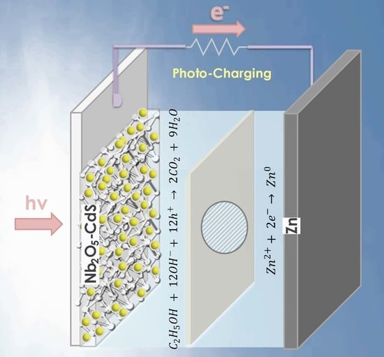
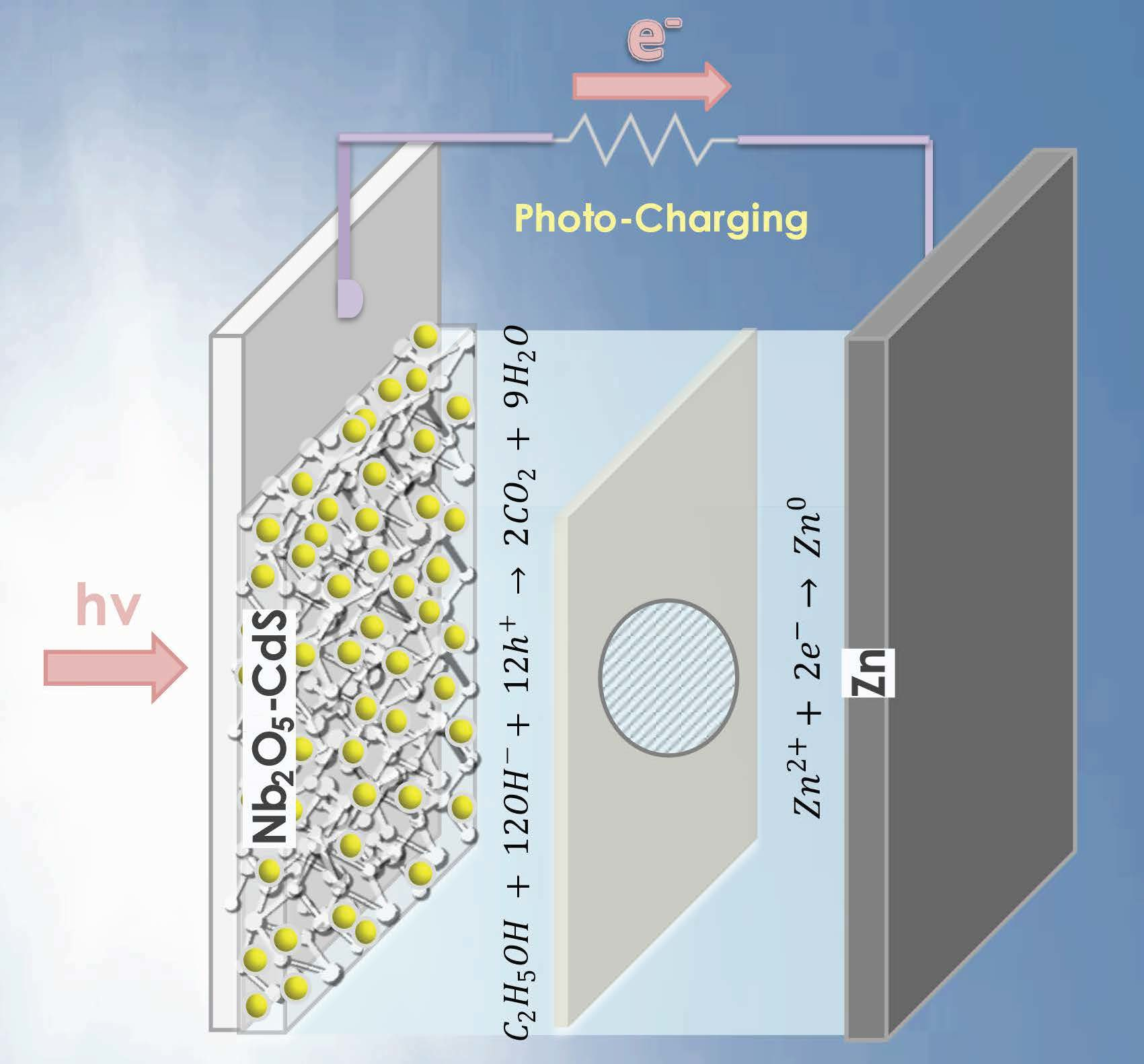
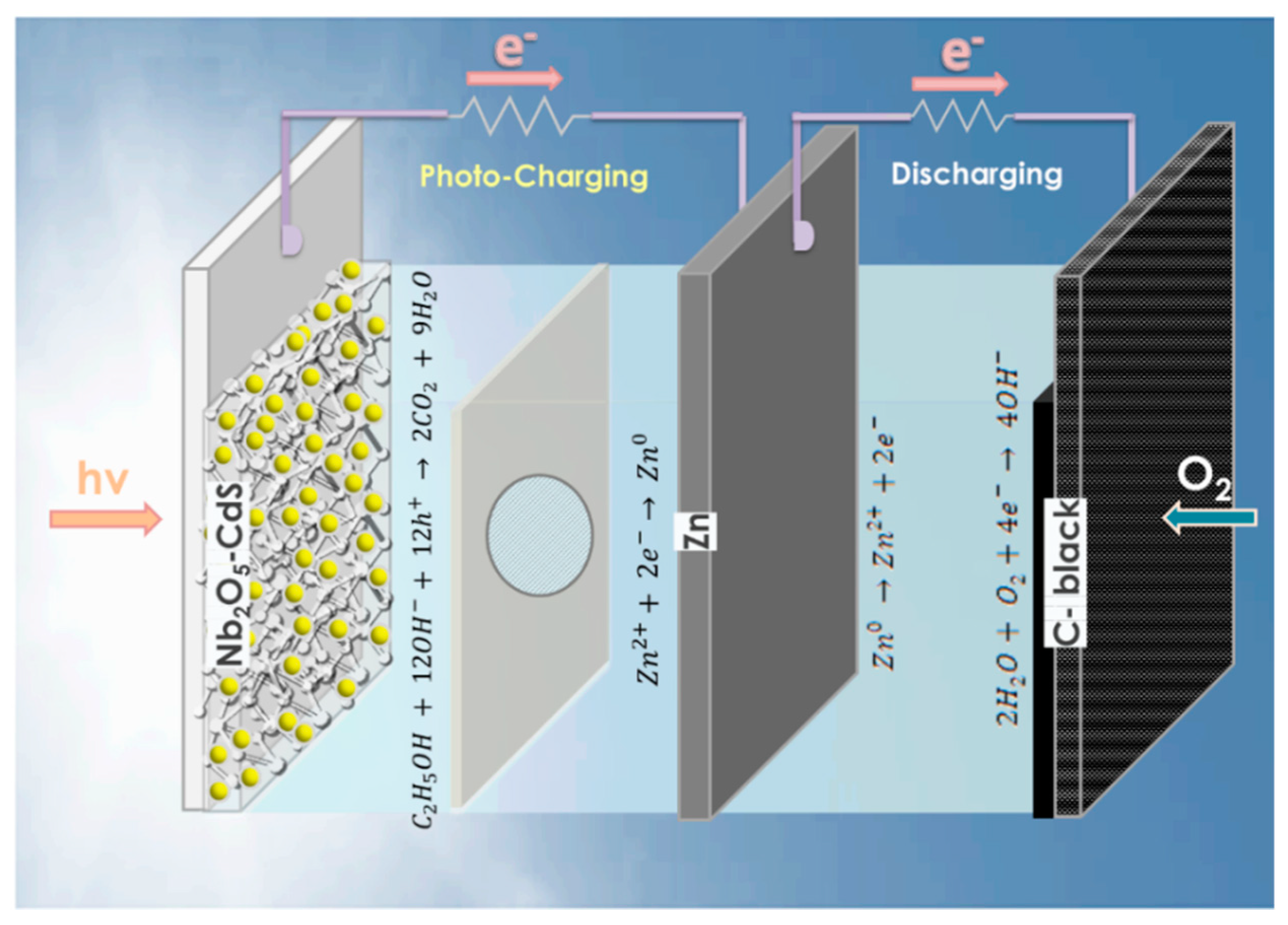
Photo-Charging a Zinc-Air Battery Using a Nb2O5-CdS Photoelectrode

by
Tatiana S. Andrade
1,*,
Antero R. S. Neto
2,
Francisco G. E. Nogueira
3,
Luiz C. A. Oliveira
1,
Márcio C. Pereira
2 and
Panagiotis Lianos
4,*
1
Department of Chemistry, Federal University of Minas Gerais (UFMG), Belo Horizonte 31270-901, Brazil
2
Institute of Science, Engineering, and Technology (ICET), Campus Mucuri, Federal University of Jequitinhonha and Mucuri Valleys (UFVJM), Teófilo Otoni 39803-371, Brazil
3
Department of Chemical Engineering, Federal University of São Carlos (UFSCar), São Carlos 13565-905, Brazil
4
Department of Chemical Engineering, University of Patras, 26500 Patras, Greece
*
Authors to whom correspondence should be addressed.
Catalysts 2022, 12(10), 1240; https://doi.org/10.3390/catal12101240
Submission received: 27 September 2022 / Revised: 12 October 2022 / Accepted: 13 October 2022 / Published: 15 October 2022
(This article belongs to the Special Issue Advanced Catalysts for Electrochemical Energy Storage and Conversion)

Abstract

:
Integrating a photoelectrode into a zinc-air battery is a promising approach to reducing the overpotential required for charging a metal-air battery by using solar energy. In this work, a photo-fuel cell employing a Nb2O5/CdS photoanode and a Zn foil as a counter-electrode worked as a photoelectrochemical battery that saves up to 1.4 V for battery charging. This is the first time a Nb2O5-based photoelectrode is reported as a photoanode in a metal-air battery, and the achieved gain is one of the top results reported so far. Furthermore, the cell consumed an organic fuel, supporting the idea of using biomass wastes as a power source for sunlight-assisted charging of metal-air batteries. Thus, this device provides additional environmental benefits and contributes to technologies integrating solar energy conversion and storage.

Graphical Abstract

1. Introduction

The broad commercialization of solar cells and other renewable energy sources has raised the urgent issue of energy storage. In addition, mobile electronics and mobile electricity have made this issue even more serious. Therefore, current research efforts have moved the focus onto the energy storage question. In what concerns solar energy, the need for two distinct systems, one for sunlight conversion and one for energy storage, limits the practicability of exploitation of sunlight as an energy source [1,2,3]. For this reason, in the present work, we propose the integration of a photoelectrode into a rechargeable metal-air battery, forming a photoelectrochemical battery. This design provides a solution regarding solar energy conversion and storage in one single device supporting practical sunlight application [3,4]. Furthermore, the proposed design offers the possibility of photoelectrocatalytic waste oxidation, which facilitates device operation and enhances battery charging capability. In addition to its environmental benefits, solar energy can help reduce the voltage necessary for charging a battery, particularly a metal-air battery, which requires a very high potential, as will also be presently seen [5,6]. However, despite the potential they carry, the development of photoelectrochemical batteries is still poorly explored.
Among the few reported investigations, most of the efforts focused on lithium–air batteries [7,8,9,10]. However, their high cost and poor safety [11,12] have promoted photoelectrochemical zinc-air batteries as the most attractive among emerging technologies. Rechargeable aqueous zinc-air batteries have drawn increased attention due to their high energy density (1086 Wh kg−1 in theory), environmental friendliness, metal abundance, and high safety [13,14]. Whereas primary zinc-air batteries have been commercialized, rechargeable zinc-air batteries still face significant challenges that should be overcome, starting with their large charging voltage, typically above 2 V [15]. In this regard, integrating a photoelectrode into a zinc-air battery has emerged as an attractive technology and has recently gained interest, but the studies are still in the early stages [16,17,18,19,20,21,22,23,24].
Studies on photo-responsive zinc-air batteries have been reported in just the last few years. One reported approach is to introduce a photo-responsive material with a typical air-electrode [17,18], such as carbon-based materials combined with the zinc electrode. For example, Lv et al. [17] used photo-responsive Ni12P5 nanoparticles coupled with nitrogen-doped carbon nanotubes, reducing the charging bias and improving the open-circuit voltage of the battery when using sunlight as the power source. Despite being attractive in terms of the bifunctionality of the electrode, this approach promotes just a slight improvement in the electric input bias, in that case only 3%, still requiring 1.9 V to charge the battery. Another strategy is to couple a photo-fuel cell with a zinc-air battery. This strategy has the potential to reduce the charging bias by at least 30% using sunlight; therefore, it creates conditions for an economically viable application [16,19,20,21,22]. However, only a few photo-responsive materials, namely metal-oxide semiconductors, such as TiO2, BiVO4, and Fe2O3, have been reported so far, leaving plenty of room for developing more advanced photoelectrochemical zinc-air batteries.
The purpose of the present work was to discuss a novel sunlight-promoted rechargeable zinc-air battery using a photoelectrode of Nb2O5, sensitized by a visible-light absorber: i.e., CdS, as shown in Figure 1. This photocatalyst was synthesized by a simple methodology consisting of a drop-casting deposition followed by the Successive Ionic Layer Adsorption and Reaction (SILAR method). Nb2O5-based materials are less popular than the above metal-oxide semiconductors, being reported more for photocatalysis applications and less for photoelectrodes. In this sense, the present work shows the potential of such a material to be employed as a photoanode, supporting its solar-driven application and expanding its exploration as a promising photo-responsive material. Nb2O5 is an n-type semiconductor that absorbs photons in the ultraviolet region (<400 nm) with a wide bandgap of 3.4 eV and a valence band position suitable for the oxidation of several fuels, such as dyes and other organic and inorganic compounds [25,26]. Its valence and conduction bands (3.0 and −0.4 eV, respectively) lie at more positive or negative energy levels than other metal oxides (e.g., Fe2O3, BiVO4, and TiO2). Thus, Nb2O5 embraces a wide range of both oxidation and reduction reactions and makes itself an attractive material for photoelectrochemistry [27]. Furthermore, combined with CdS, the photoelectrode can provide both visible-light absorption capacity (>400 nm) and high oxidation performance [28,29,30]. Therefore, the photoelectrochemical battery proposed here, using Nb2O5-CdS as the photoanode and zinc as the metal electrode, provided about 50–60% of electric input energy saving, with up to 1.4 V of voltage gain. In addition, the designed device consumed organic fuel. To facilitate data extraction and attain a satisfactory reproducibility level, we have used ethanol as a model fuel. It is understood that for practical applications, it is preferable to use biomass wastes, thus offering the means for an additional environmental benefit. In this sense, the proposed model combines solar energy conversion, energy storage in a battery, and exploitation of biomass in one single device. This is a great advantage compared to, for example, traditional photovoltaics, where solar panels, batteries, and environmental remediation processes must be carried out in separate devices.

2. Results and Discussion

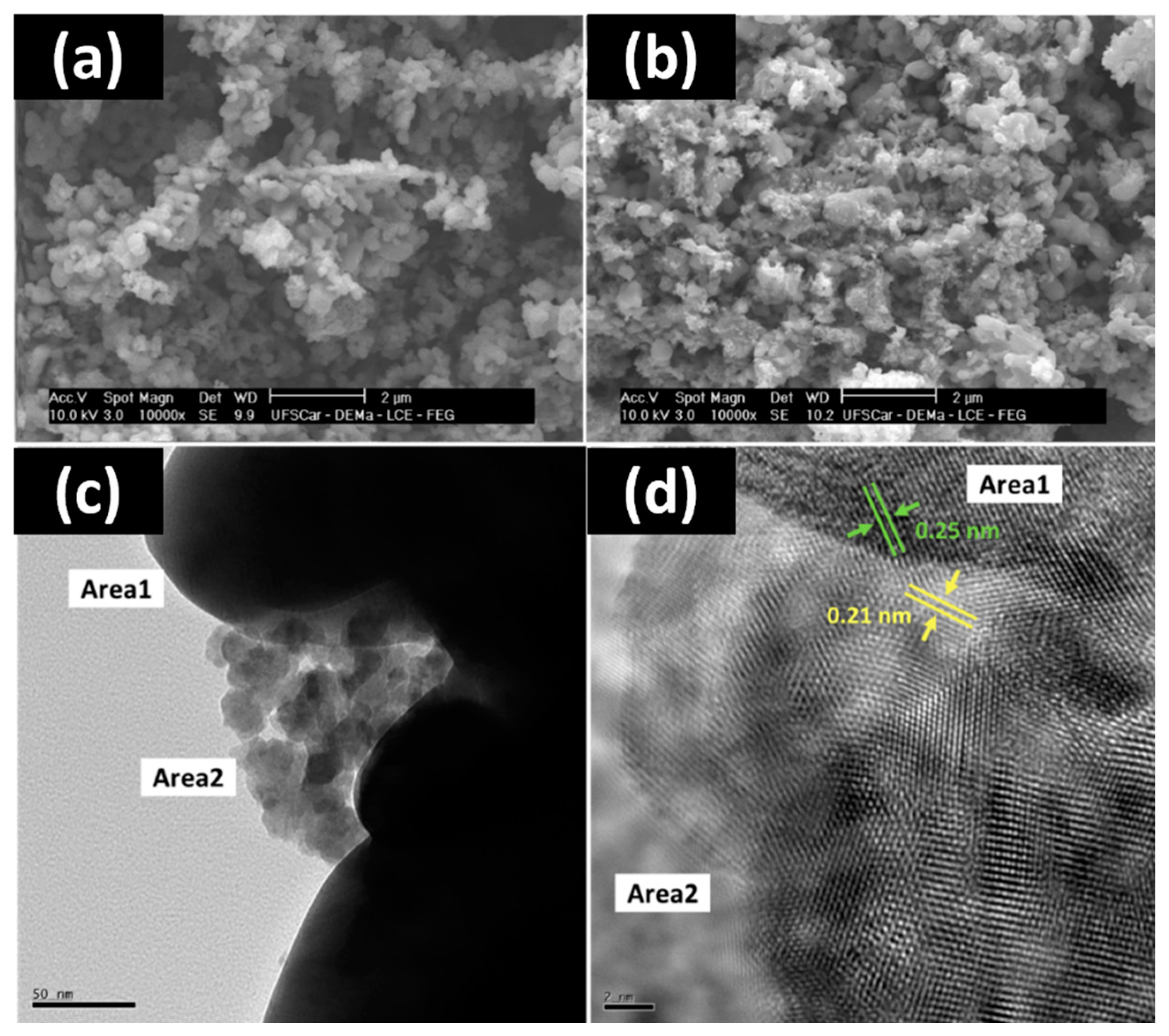
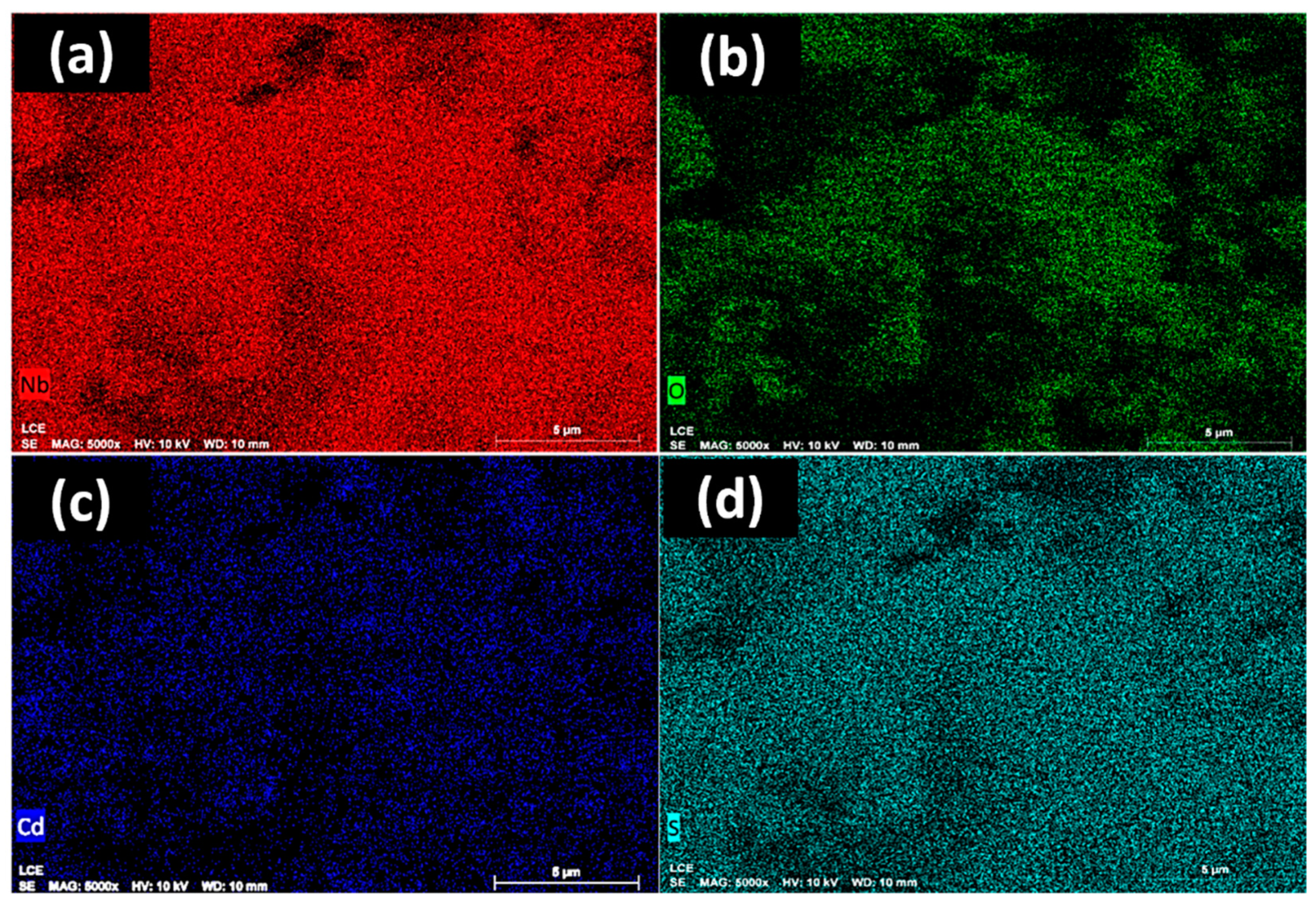
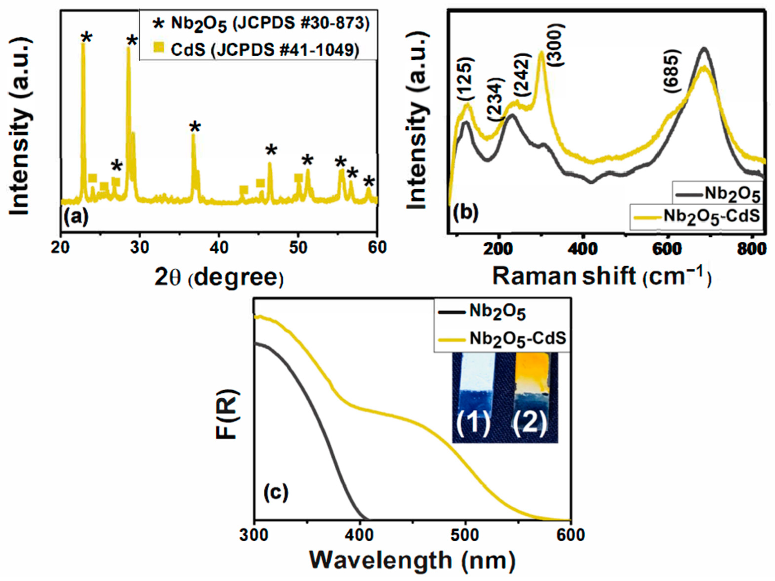
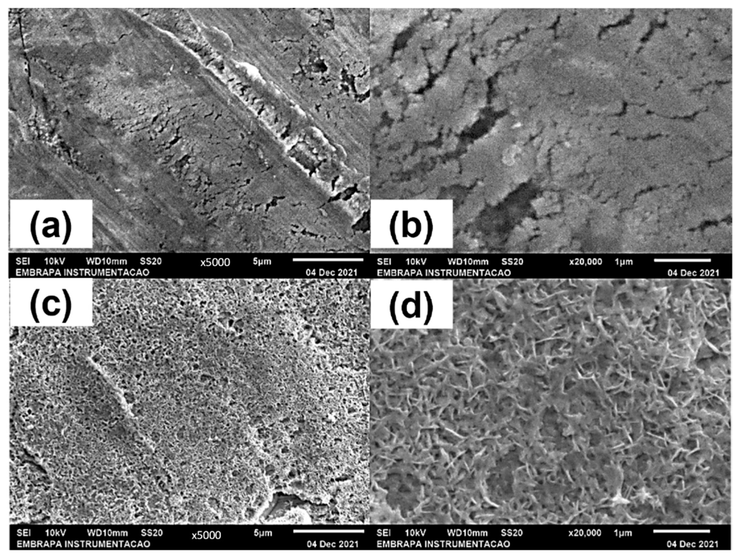
2.1. Characterization of the Electrodes

The morphological characterization of the photoelectrode is displayed in Figure 2a–d. The SEM image of Nb2O5 film, Figure 2a, indicates the presence of nanoparticles in a size range of around 150–200 nm. The addition of CdS to the film has shown more agglomerated particles, indicating the presence of dots inside the mesoporous structure of the formed Nb2O5, as displayed in Figure 2b. The TEM displayed in Figure 2c supported the SEM images showing the combination of the two semiconductors with the Nb2O5 big particles represented by the dark area (Area1) around the CdS particles (Area2). HR-TEM, Figure 2d, revealed calculated lattice spacings of 0.25 and 0.21 nm, respectively, for Nb2O5 and CdS at the composite interface. Meanwhile, EDS mapping images of the Nb2O5-CdS film show a uniform distribution of the elements Nb, O, Cd, and S, as seen in Figure 3a–d.
The X-ray diffraction pattern for the composite, displayed in Figure 4a, has shown the formation of the Nb2O5 orthorhombic phase (JCPDS card #30-873) and the CdS hexagonal phase (JCPDS card #41-1049). Thus, the calculated lattice spacings previously presented in Figure 2d, (0.25 and 0.21 nm) agree with the d-spacings of the (181) plane of Nb2O5 (d181  =  0.2453 nm) and the (110) plane of CdS (d110  =  0.2071 nm). Raman spectra (Figure 4b) have supported XRD results, revealing typical bands that indicate the formation of Nb2O5, with the characteristic peaks at 125, 234, and 686 cm−1 belonging to Nb2O5. The Raman spectra for the Nb2O5-CdS film show similar region peaks at 125 and 686 cm−1 as the Nb2O5 phase. A relevant change in the spectrum with the addition of CdS is observed at the peak of 300 cm−1, attributed to the vibrational mode of hexagonal CdS. Furthermore, the peak at 234 cm−1, shown in Figure 4b, is right-shifted to 242 cm−1, indicating the interaction between Nb2O5 and CdS. Diffuse reflectance spectroscopy (DRS) spectra, shown in Figure 4c, have shown that the Nb2O5 film absorbs photons in the ultraviolet region (<400 nm, corresponding to a bandgap higher than 3.2 eV), but its absorption spectra expand up to 550 nm (corresponding to a bandgap of 2.3 eV) with CdS addition, which demonstrates the composite potential to act as a visible light-activated photoelectrode in a photoelectrochemical zinc-air battery. The images inserted in Figure 4c show the white image for the Nb2O5 film (1) and the change to yellow upon the addition of CdS (2).

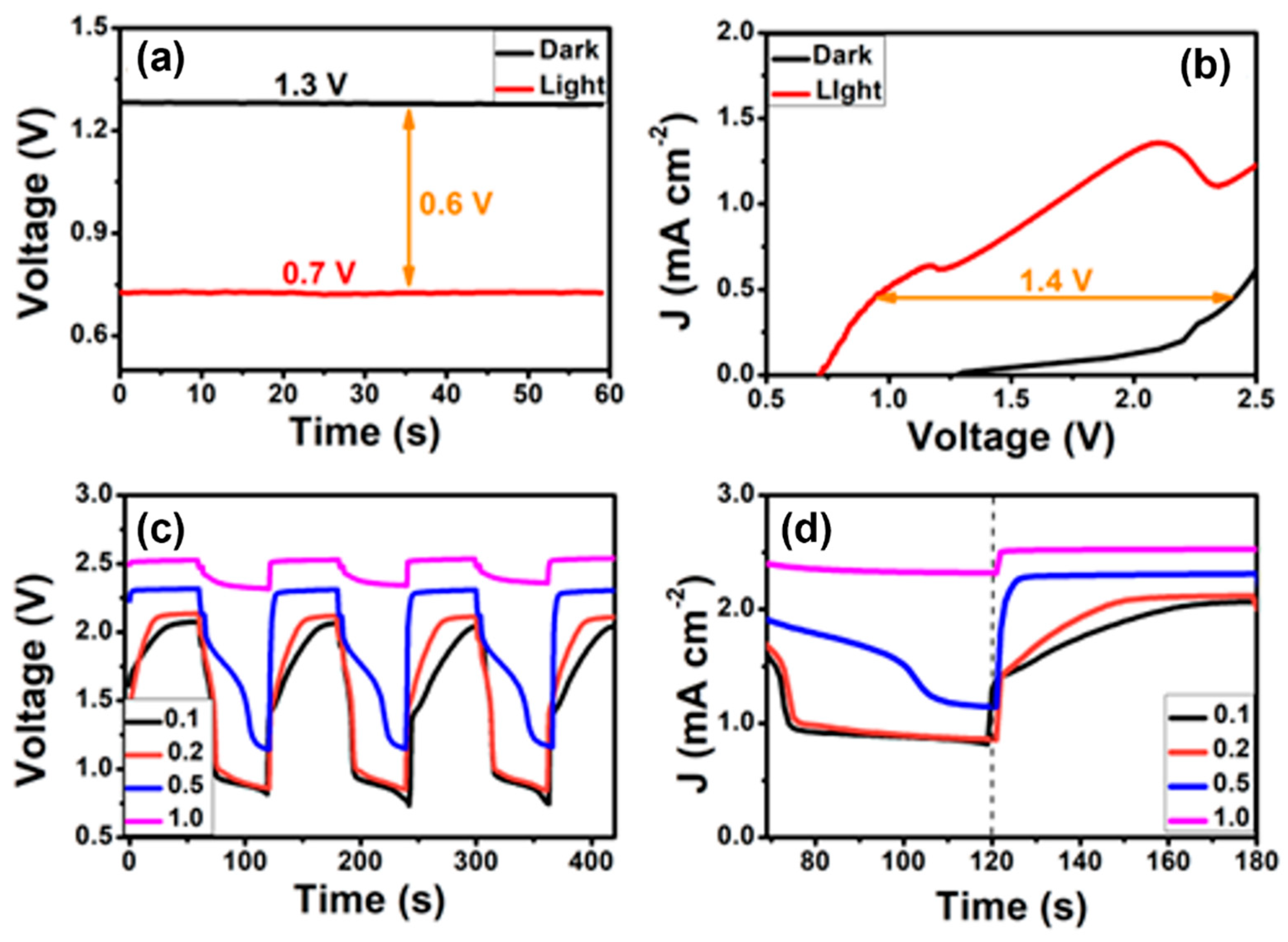
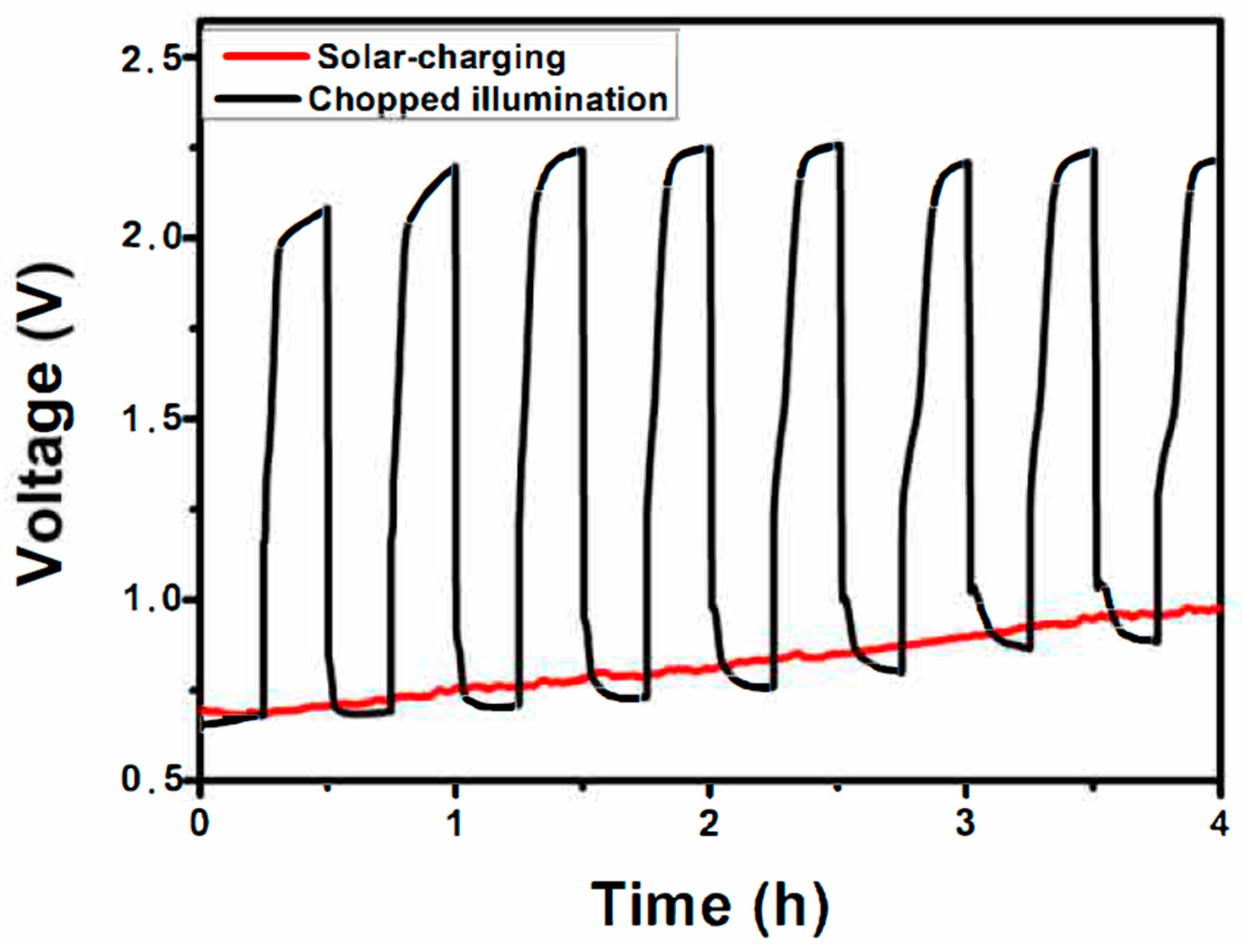
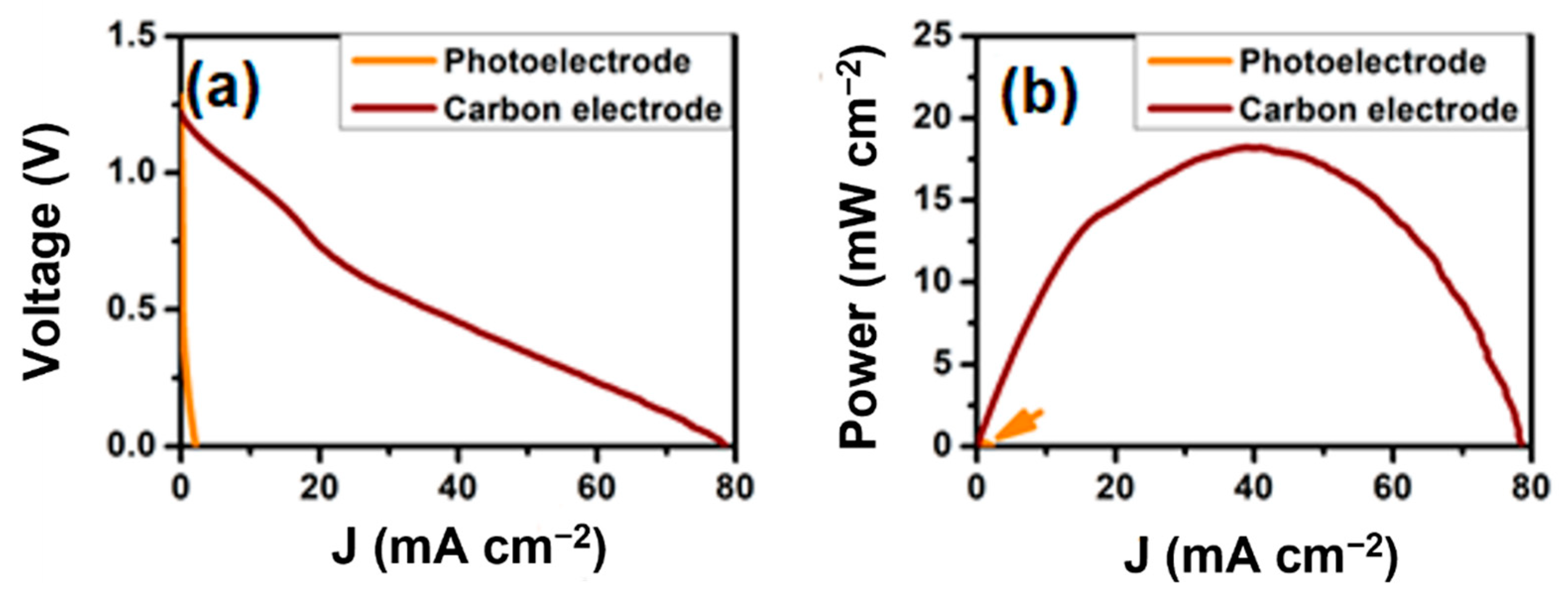
2.2. Photocharging of the Zinc-Air Battery

To charge the battery, electrons should flow from the cell photoanode to the counter electrode, i.e., the zinc foil (cf. photo-charging mode in Figure 1). When the Zn foil comes into contact with the electrolyte, it tends to produce current in the opposite direction, i.e., to send electrons toward the photoelectrode, becoming the anode itself. To overcome this bias, it is necessary to apply an external bias. The external bias is the largest in the dark, but when the photoelectrode is illuminated, it produces photoelectrons and decreases the necessity of an external bias. This condition has been demonstrated by the following experiments. In the first case, the situation was tested in open-circuit conditions, i.e., at zero current, in the dark, and under illumination. In this sense, it is possible to determine the bias necessary to charge the battery. As shown in Figure 5a, the cell in the dark delivered an open-circuit voltage of 1.3 V. This value is less than the theoretical value of 1.65 V but follows the expected practical values for Zn-air batteries [15]. Under illumination, the open-circuit voltage went down to 0.7 V because of the opposite potential generated by the photoanode electrode, providing 0.6 V of voltage gain and more than 45% of input energy saving. Lowering the open-circuit potential demonstrates that the cell is photo-responsive and sets a minimum value for its charging bias under illumination.
The current flowing through the cell can be monitored by varying the external bias. Thus, we can evaluate the battery photo-range area and estimate the voltage required to charge the battery when using a certain current passing through the cell. The results are displayed in Figure 5b. The J-V curve obtained in the dark suggests that a very strong bias is necessary to charge the battery, i.e., to move electrons from the photoanode to the Zn foil cathode, even at very small currents. Indeed, the threshold for the forward current was obtained at a bias larger than about 1.3 V, and for larger currents, more than 2 V, were necessary. Upon illumination, a substantial photocurrent was generated with a threshold of around 0.7 V. The voltage gain for a current flow of about 0.5 mA cm−2 was as high as 1.4 V. This voltage gain corresponds to an energy saving of around 50–60%, highlighting that this cell is an attractive device for saving electric energy to charge the battery by solar irradiation exploitation. This voltage gain is one of the top results among photoelectrochemical batteries. It is comparable to reported works employing modified TiO2 as the photoelectrode, where the gain was in the range of 1.3 to 2.0 V [19,20]. At higher charging currents, the J-V curves of Figure 5b indicate that the voltage gain is smaller and tends to have minimal values above 1 mA cm−2.
Thus, to further evaluate the photo-charging capacity of the system, we also measured the cell in the galvanostatic mode at different currents through chopped illumination to get dark–light cycles. We have chosen current values corresponding to the photocurrent area in the range of 0.1 to 1.0 mA cm−2. The obtained curves are displayed in Figure 5c, showing three subsequent cycles. Figure 5d displays a zoom of the second cycle, demonstrating that, as expected, the voltage change was faster when the current was higher and achieved higher values when it demanded higher currents to pass through the system. The data in Figure 5c (and Figure 5d) verify the observations made in the previous paragraph, i.e., that the voltage gain was larger when the charging current was lower. In other words, when the solar charging is slower (lower current density values are chosen), more charging time would be required, but the voltage gain is larger, making the system more attractive in terms of energy input saving.
To evaluate the system regarding stability issues, we performed both dark–light charging cycles and continuous photo-charging at 0.2 mA cm−2 for several hours. The galvanostatic charge-discharge profile is represented by the black line in Figure 6, where the lower values correspond to the (photo)-charging while the upper values correspond to discharging. Note that the bottom lines of the chopped illumination curve (black line) represent the photo-assisted charging and matching the potentials of the continuous photo-charging curve (red line), showing the system stability during illumination variation. Thus, it is essential to highlight that the above system demonstrated satisfactory stability, as shown in Figure 6, with more than 50% energy-saving after several cycles and still requiring less than 1.0 V for its charging under illumination.
As a consequence of the charging process, Zn metal was deposited on the zinc electrode. Thus the scanning electron microscopy images of the Zn foil revealed a typical metal surface before the photo-charging, displayed in Figure 7a,b. After the photo-charging, its surface is completely covered by nano-flakes, indicating the formation of metallic Zn during the process, as shown in Figure 7c,d. The formation of metallic Zn indicates that the reduction reaction of Zn ions occurred, as proposed in Figure 1 ( Zn 2 + + 2 e Zn 0 ) , demonstrating that solar charging was successful. The XRD pattern detected additional peaks, which indicated the formation of the zinc oxide crystal phase (JCPDS card #21-1486) after charging instead of just the zinc metal (JCPDS card #4-831) identified in the zinc foil before charging. XRD patterns for the Zn foils before and after charging are displayed in Figure 8. The presence of zinc oxide on the surface of the electrode is expected because of oxidation due to the presence of the alkaline electrolyte. The photoelectrode did not suffer any detectable modifications during the stability test. Thus, the XRD lines were the same after the test, like those recorded in Figure 4a, while DRS measurements did not detect any shift in the absorption threshold. We believe that the relatively low current flowing through the system (0.2 mA cm−2) allowed sustainable operation, as also previously observed [31].
The current range for the battery photo-charging is associated with how fast the battery could be charged with sunlight assistance. Thus, faster battery charging (larger current) has, as a consequence, lower energy savings. Thus, the present system requires the battery to be photo-charged at low currents to save about 50–60% of electric input bias using solar irradiation. In any case, the rate of battery charging does not influence the battery discharge performance. The battery discharge was not the main goal of this work, but some considerations are worth mentioning. As was already demonstrated in Figure 5a,b, the open-circuit voltage in the dark using the present photoelectrode was about 1.3 V. This corresponds to a Zn-air battery with the photoanode playing the role of the air electrode. However, the photoelectrode cannot deliver satisfactory power density to compete with conventional zinc-air batteries and pure air electrodes. For this reason, we inserted a third electrode in the zinc compartment, a typical air-electrode made with carbon cloth and carbon black, to operate the battery discharging mode, as illustrated in Figure 1 (discharging mode). We have adopted the simplest oxygen reduction reaction (ORR) catalyst, i.e., mesoporous graphite (carbon black), for the discharging operation. Better performance ORR response in metal-air batteries can be achieved by adding other materials, such as Pt, MnO2, and V complex [32,33,34]. J x V and P curves of both systems are displayed in Figure 9a,b. With the third electrode, the battery demonstrated a similar open-circuit voltage value but gave a much higher short-circuit current, reaching around 80 mA cm−2 (Figure 9a). This is about 40 times greater than the system using the photoelectrode as the air-electrode. Regarding the power density (Figure 9b), a 100-times-higher value was achieved compared to the system using the photoelectrode as the air-electrode. This result is expected since the photoanode is not a real air electrode, relying only on oxygen dissolved in the electrolyte. Similar behavior is observed by reported works using photoelectrodes to charge zinc-air batteries, not achieving an open-circuit current higher than 6 mA cm−2 and power density higher than 0.75 mW cm−2 [19,20,21,22]. Very recently, a study of a photo-rechargeable Zn-air battery using a ZnO-CuO composite has shown better bifunctionality performance [35]. In this case, the bifunctional performance is attributed to the Cu redox modifications during charge/discharge. Even though this performance might indicate another investigation route for the photoelectrochemical batteries, its performance as an air electrode is still significantly lower compared to conventional air electrodes. Thus, further studies on photoelectrochemical batteries should focus on overcoming this limitation or, as we proposed here, consider the simple solution of a third electrode to work in the discharging mode by just switching the connections from charge to discharge mode. Either way, the present system has demonstrated an attractive design to save substantial input electric bias by exploiting solar irradiation at the expense of an organic fuel, which provides environmental and economic benefits.

3. Materials and Methods

3.1. Photoelectrode Construction

The reactor employed was designed as seen in Figure 1; its main components were a photoelectrode and a Zn-foil (Alpha Aesar) counter electrode. For the photoelectrode construction, Nb2O5 particles have been deposited by the drop-casting method on a Fluorine-Doped Tin Oxide (FTO)-coated conductive glass substrate (10 mm × 20 mm × 2 mm, 16 Ω cm−2). First, we prepared a dispersion of 10 mg of Nb2O5 (Optical grade, orthorhombic crystalline phase, 99.8% purity; Companhia Brasileira de Metalurgia e Mineração (CBMM), Araxa, Brazil) in 4 mL of isopropanol. The dispersion was homogenized in an ultrasound mixer for 10 min and full-deposited through 30 µL-layers using an automatic pipette, followed by calcination at 550 °C for 2 h. After that, CdS nanoparticles were formed within mesoporous niobium pentoxide by 15 successive SILAR cycles, using 0.1 M of CdCl2 and Na2S. To evaluate the battery discharging process using a typical air electrode, a third electrode connected to the Zn foil, as illustrated in Figure 1, has been prepared with carbon nanoparticles deposited on carbon cloth (Fuel Cell Earth, Woburn, MA, USA). For that, we mixed 0.25 g of carbon black (Cabot Corporation, Vulcan XC72, Billerica, MA, USA), 100 µL of Polytetrafluoroethylene (PTFE) (Sigma-Aldrich, St. Louis, MO, USA), and 1.2 mL of distilled water deposited on carbon cloth, followed by calcination at 340 °C.

3.2. Morphological and Photoelectrochemical Characterization

The constructed photoelectrode and the zinc electrode morphology were analyzed by scanning electron microscopy (SEM) using a Philips® XL-30 FEG microscope (Eindhoven, The Netherlands). The crystal structures of the photoelectrode were determined by X-ray diffraction using an XRD 6000 diffractometer (Shimadzu, Kyoto, Japan) and Cu radiation, and the qualitative analysis was performed using the Crystallographica Search-Match Software (version 2,0,2,0). Raman spectra were obtained using a micro spectrometer (Horiba Jobin-Yvon Raman LabRAM, Palaiseau, France) at room temperature with a 512 nm line He Ne 5.9 mW laser as an excitation source through a microscope (Tokyo, Japan). The optical properties of the photoelectrode were examined by UV-Vis diffuse reflectance spectroscopy using a UV 2700 spectrophotometer (Shimadzu, Kyoto, Japan). As seen in Figure 1, the cell was a two-compartment cell using a 20 μm porous glass-frit as the separator membrane. The anode compartment was filled with 0.5 M aqueous NaOH and 5% v/v ethanol, while 2.0 M aqueous NaOH and 0.1 M Zn(CH3COO)2 were used in the zinc compartment, supporting the charging process through the addition of zinc ions. Light (Xe lamp, 100 mW cm−2) reached the photoelectrode position through the FTO slide. We carried out the photoelectrochemical tests using an Autolab potentiostat PGSTAT128N (Utrecht, The Netherlands). No reference electrode was used in either case. For the photo-charging process evaluation, we followed a galvanostatic method. The stability test was performed by the galvanostatic method under lighting or charge-discharge cycles as employed in previous works [19,20,21,22]. To evaluate the system using a typical air electrode as a third electrode, we connected the zinc as the working electrode and the carbon electrode as the counter-electrode, both immersed in the same electrolyte, as illustrated in Figure 1.

4. Conclusions

The present work has shown that charging a Zn-air battery using Nb2O5-CdS as the photoelectrode and ethanol as model fuel for organic wastes is possible. Furthermore, the system demonstrates a relevant technological advantage since it offers an electric voltage gain of 1.4 V, which corresponds to at least 50% energy-saving under illumination. Thus, this work supports the exploitation of solar energy as a source for the charging of metal-air batteries and brings promising insights for developing more advanced photo-responsive batteries. This work has also promoted Nb2O5 as a very useful semiconductor photocatalyst that is also applicable to solar-assisted Zn-air charging.

Author Contributions

Conceptualization, T.S.A.; investigation, T.S.A. and A.R.S.N.; writing—original draft, T.S.A.; methodology, F.G.E.N.; writing—review and editing, F.G.E.N., M.C.P. and P.L.; supervision, L.C.A.O. and M.C.P. All authors have read and agreed to the published version of the manuscript.

Funding

This research was funded by FAPEMIG (grant numbers REDE-113/10; RED00520-16; CEX-112-10; CEX-RED-00010–14; PPM-00104-17), CNPq (grant numbers 442820/2014-3; 304598/2014-3; 301839/2017-4; 307746/2021-6), INCT MIDAS, FAPESP (2018/09723-9), MCTI/FINEP and CAPES (Code 001) T.S.A. thanks CNPq (163579-2020-2) for the postdoctoral fellowship.

Institutional Review Board Statement

Not applicable.

Informed Consent Statement

Not applicable.

Data Availability Statement

The data presented are available on request from the authors.

Acknowledgments

The authors thank the Laboratory of Structural Characterization (LCE/DEMa/UFSCar) for the general facilities.

Conflicts of Interest

The authors declare no conflict of interest.

References

  1. Zeng, Q.; Lai, Y.; Jiang, L.; Liu, F.; Hao, X.; Wang, L.; Green, M.A. Integrated Photorechargeable Energy Storage System: Next-Generation Power Source Driving the Future. Adv. Energy Mater. 2020, 10, 1903930. [Google Scholar] [CrossRef]
  2. Wu, Y.; Li, C.; Tian, Z.; Sun, J. Solar-Driven Integrated Energy Systems: State of the Art and Challenges. J. Power Sources 2020, 478, 228762. [Google Scholar] [CrossRef]
  3. Li, Q.; Liu, Y.; Guo, S.; Zhou, H. Solar Energy Storage in the Rechargeable Batteries. Nano Today 2017, 16, 46–60. [Google Scholar] [CrossRef]
  4. Yan, N.F.; Gao, X.P. Photo-Assisted Rechargeable Metal Batteries for Energy Conversion and Storage. Energy Environ. Mater. 2021, 5, 439–451. [Google Scholar] [CrossRef]
  5. Kraytsberg, A.; Ein-Eli, Y. The Impact of Nano-Scaled Materials on Advanced Metal-air Battery Systems. Nano Energy 2013, 2, 468–480. [Google Scholar] [CrossRef]
  6. Li, Y.; Lu, J. Metal-Air Batteries: Will They Be the Future Electrochemical Energy Storage Device of Choice? ACS Energy Lett. 2017, 2, 1370–1377. [Google Scholar] [CrossRef]
  7. Liu, Y.; Li, N.; Wu, S.; Liao, K.; Zhu, K.; Yi, J.; Zhou, H. Reducing the Charging Voltage of a Li-O2 Battery to 1.9 v by Incorporating a Photocatalyst. Energy Environ. Sci. 2015, 8, 2664–2667. [Google Scholar] [CrossRef]
  8. Liu, Y.; Li, N.; Liao, K.; Li, Q.; Ishida, M.; Zhou, H. Lowering the Charge Voltage of Li-O2 Batteries: Via an Unmediated Photoelectrochemical Oxidation Approach. J. Mater. Chem. A 2016, 4, 12411–12415. [Google Scholar] [CrossRef]
  9. Feng, Y.; Xue, H.; Wang, T.; Gong, H.; Gao, B.; Xia, W.; Jiang, C.; Li, J.; Huang, X.; He, J. Enhanced Li2O2 Decomposition in Rechargeable Li-O2 Battery by Incorporating WO3 Nanowire Array Photocatalyst. ACS Sustain. Chem. Eng. 2019, 7, 5931–5939. [Google Scholar] [CrossRef]
  10. Tan, P.; Xiao, X.; Dai, Y.; Cheng, C.; Ni, M. Photo-Assisted Non-Aqueous Lithium-Oxygen Batteries: Progress and Prospects. Renew. Sustain. Energy Rev. 2020, 127, 109877. [Google Scholar] [CrossRef]
  11. Grande, L.; Paillard, E.; Hassoun, J.; Park, J.B.; Lee, Y.J.; Sun, Y.K.; Passerini, S.; Scrosati, B. The Lithium/Air Battery: Still an Emerging System or a Practical Reality? Adv. Mater. 2015, 27, 784–800. [Google Scholar] [CrossRef]
  12. Liu, Y.; He, P.; Zhou, H. Rechargeable Solid-State Li–Air and Li–S Batteries: Materials, Construction, and Challenges. Adv. Energy Mater. 2018, 8, 1701602. [Google Scholar] [CrossRef]
  13. Fu, J.; Cano, Z.P.; Park, M.G.; Yu, A.; Fowler, M.; Chen, Z. Electrically Rechargeable Zinc-air Batteries: Progress, Challenges, and Perspectives. Adv. Mater. 2017, 29, 1604685. [Google Scholar] [CrossRef]
  14. Chen, X.; Zhou, Z.; Karahan, H.E.; Shao, Q.; Wei, L.; Chen, Y. Recent Advances in Materials and Design of Electrochemically Rechargeable Zinc-air Batteries. Small 2018, 14, 1801929. [Google Scholar] [CrossRef]
  15. Li, Y.; Dai, H. Recent Advances in Zinc-Air Batteries. Chem. Soc. Rev. 2014, 43, 5257–5275. [Google Scholar] [CrossRef] [Green Version]
  16. Du, D.; Zhao, S.; Zhu, Z.; Li, F.; Chen, J. Photo-Excited Oxygen Reduction and Oxygen Evolution Reactions Enable a High-Performance Zn-air Battery. Angew. Chem.—Int. Ed. 2020, 59, 18140–18144. [Google Scholar] [CrossRef]
  17. Lv, J.; Abbas, S.C.; Huang, Y.; Liu, Q.; Wu, M.; Wang, Y.; Dai, L. A Photo-Responsive Bifunctional Electrocatalyst for Oxygen Reduction and Evolution Reactions. Nano Energy 2018, 43, 130–137. [Google Scholar] [CrossRef]
  18. Mathur, A.; Kaushik, R.; Halder, A. Visible-Light-Driven Photo-Enhanced Zinc-Air Batteries Using Synergistic Effect of Different Types of MnO2nanostructures. Catal. Sci. Technol. 2020, 10, 7352–7364. [Google Scholar] [CrossRef]
  19. Andrade, T.S.; Pereira, M.C.; Lianos, P. High Voltage Gain in Photo-Assisted Charging of a Metal-Air Battery. J. Electroanal. Chem. 2020, 878, 114559. [Google Scholar] [CrossRef]
  20. Andrade, T.S.; Dracopoulos, V.; Pereira, M.C.; Lianos, P. Unmediated Photoelectrochemical Charging of a Zn-Air Battery: The Realization of the Photoelectrochemical Battery. J. Electroanal. Chem. 2020, 878, 114709. [Google Scholar] [CrossRef]
  21. Andrade, T.S.; Sena, I.C.; de Oliveira, L.C.A.; Lianos, P.; Pereira, M.C. Decreasing the Charging Voltage of a Zinc-Air Battery Using a Bifunctional W:BiVO4/V2O5 Photoelectrode and Sulfite as a Sacrificial Agent. Mater. Today Commun. 2021, 28, 9–12. [Google Scholar] [CrossRef]
  22. Liu, X.; Yuan, Y.; Liu, J.; Liu, B.; Chen, X.; Ding, J.; Han, X.; Deng, Y.; Zhong, C.; Hu, W. Utilizing Solar Energy to Improve the Oxygen Evolution Reaction Kinetics in Zinc-air Battery. Nat. Commun. 2019, 10, 4767. [Google Scholar] [CrossRef] [Green Version]
  23. Tomon, C.; Sarawutanukul, S.; Duangdangchote, S.; Krittayavathananon, A.; Sawangphruk, M. Photoactive Zn-Air Batteries Using Spinel-Type Cobalt Oxide as a Bifunctional Photocatalyst at the Air Cathode. Chem. Commun. 2019, 55, 5855–5858. [Google Scholar] [CrossRef]
  24. Sarawutanukul, S.; Tomon, C.; Duangdangchote, S.; Phattharasupakun, N.; Sawangphruk, M. Rechargeable Photoactive Zn-Air Batteries Using NiCo2S4 as an Efficient Bifunctional Photocatalyst towards OER/ORR at the Cathode. Batter. Supercaps 2020, 3, 541–547. [Google Scholar] [CrossRef]
  25. Su, K.; Liu, H.; Gao, Z.; Fornasiero, P.; Wang, F. Nb2O5-Based Photocatalysts. Adv. Sci. 2021, 8, 2003156. [Google Scholar] [CrossRef]
  26. Zhao, Y.; Zhou, X.; Ye, L.; Chi Edman Tsang, S. Nanostructured Nb2O5 Catalysts. Nano Rev. 2012, 3, 17631. [Google Scholar] [CrossRef] [Green Version]
  27. Marschall, R. Semiconductor Composites: Strategies for Enhancing Charge Carrier Separation to Improve Photocatalytic Activity. Adv. Funct. Mater. 2014, 24, 2421–2440. [Google Scholar] [CrossRef]
  28. Oliveira, L.C.A.; Oliveira, H.S.; Mayrink, G.; Mansur, H.S.; Mansur, A.A.P.; Moreira, R.L. One-Pot Synthesis of CdS@Nb2O5 Core–Shell Nanostructures with Enhanced Photocatalytic Activity. Appl. Catal. B Environ. 2014, 152–153, 403–412. [Google Scholar] [CrossRef]
  29. Zu, D.; Song, H.; Wang, Y.; Chao, Z.; Li, Z.; Wang, G.; Shen, Y.; Li, C.; Ma, J. One-Pot in-Situ Hydrothermal Synthesis of CdS/Nb2O5/Nb2C Heterojunction for Enhanced Visible-Light-Driven Photodegradation. Appl. Catal. B Environ. 2020, 277, 119140. [Google Scholar] [CrossRef]
  30. Yue, Z.; Liu, A.; Zhang, C.; Huang, J.; Zhu, M.; Du, Y.; Yang, P. Noble-Metal-Free Hetero-Structural CdS/Nb2O5/N-Doped-Graphene Ternary Photocatalytic System as Visible-Light-Driven Photocatalyst for Hydrogen Evolution. Appl. Catal. B Environ. 2017, 201, 202–210. [Google Scholar] [CrossRef]
  31. Andrade, T.S.; Dracopoulos, V.; Keramidas, A.; Pereira, M.C.; Lianos, P. Charging a vanadium redox battery with a photo (catalytic) fuel cell. Sol. Energy Mater. Sol. Cells 2021, 221, 110889. [Google Scholar] [CrossRef]
  32. Katsoufis, P.; Mylona, V.; Politis, C.; Avgouropoulos, G.; Lianos, P. Study of Some Basic Operation Conditions of an Al-Air Battery Using Technical Grade Commercial Aluminum. J. Power Sources 2020, 450, 227624. [Google Scholar] [CrossRef]
  33. Katsoufis, P.; Katsaiti, M.; Mourelas, C.; Andrade, T.S.; Dracopoulos, V.; Politis, C.; Avgouropoulos, G.; Lianos, P. Study of a Thin Film Aluminum-Air Battery. Energies 2020, 13, 1447. [Google Scholar] [CrossRef] [Green Version]
  34. Keramidas, A.D.; Hadjithoma, S.; Drouza, C.; Andrade, T.S.; Lianos, P. Four Electron Selective O2reduction by a Tetranuclear Vanadium(IV/V)/Hydroquinonate Catalyst: Application in the Operation of Zn-Air Batteries. New J. Chem. 2022, 46, 470–479. [Google Scholar] [CrossRef]
  35. Bu, D.; Batmunkh, M.; Zhang, Y.; Li, Y.; Qian, B.; Lan, Y.; Hou, X.; Li, S.; Jia, B.; Song, X.M.; et al. Rechargeable Sunlight-Promoted Zn-Air Battery Constructed by Bifunctional Oxygen Photoelectrodes: Energy-Band Switching between ZnO/Cu2O and ZnO/CuO in Charge-Discharge Cycles. Chem. Eng. J. 2022, 433, 133559. [Google Scholar] [CrossRef]
Figure 1. Illustration of the reactor where a Nb2O5-CdS photoelectrode is used to photo-charge a typical Zn-air battery through C2H5OH oxidation.
Catalysts 12 01240 g001
Figure 2. SEM images of Nb2O5 (a) and Nb2O5-CdS (b). TEM (c) and HR-TEM (d) images of Nb2O5-CdS (Area1–Area2) and the calculated lattice spacings (0.25 and 0.21 nm).
Catalysts 12 01240 g002
Figure 3. EDS mapping images for the elements: Nb (a), O (b), Cd (c), and S (d).
Catalysts 12 01240 g003
Figure 4. X-ray diffraction pattern for Nb2O5-CdS composite (a). Raman spectra for Nb2O5 and Nb2O5-CdS samples (b). DRS spectra for Nb2O5 inserted image (1) and Nb2O5-CdS inserted image (2) (c).
Catalysts 12 01240 g004
Figure 5. Open-circuit voltage measurements (a), current density-voltage curves (b), chronopotentiometry through chopped illumination (c), and zoom of the second cycle (d) for a cell comprising a Nb2O5-CdS photoelectrode and zinc as the counter-electrode in an alkaline electrolyte.
Catalysts 12 01240 g005
Figure 6. Stability test during several hours of operation at continuous (red line) and chopped illumination (black line) for the system composed of Nb2O5-CdS as photoelectrode and Zn as the counter-electrode in an alkaline electrolyte. For the chopped illumination, the lines on the bottom represent the photo-assisted charging, matching the potentials shown by the red curve. The current density was 0.2 mA cm−2.
Catalysts 12 01240 g006
Figure 7. Scanning electron microscope images of the Zn foil before use (a) and (b), and after solar-assisted charging (c) and (d) at two different magnifications: the scale bar is 5 µm in (a) and (c) and 1 µm in (b) and (d).
Catalysts 12 01240 g007
Figure 8. X-ray diffraction patterns for Zn foil before and after charging.
Catalysts 12 01240 g008
Figure 9. J × V (a) and J × P curves (b) for the zinc-air battery discharging using either a Nb2O5-CdS photoelectrode or a typical carbon electrode as the air electrode.
Catalysts 12 01240 g009
Publisher’s Note: MDPI stays neutral with regard to jurisdictional claims in published maps and institutional affiliations.

