Review

Fundamentals of Gas Diffusion Electrodes and Electrolysers for Carbon Dioxide Utilisation: Challenges and Opportunities

by
Sandra Hernandez-Aldave
and
Enrico Andreoli
*
Energy Safety Research Institute, College of Engineering, Swansea University, Bay Campus, Fabian Way, Swansea SA1 8EN, UK
*
Author to whom correspondence should be addressed.
Catalysts 2020, 10(6), 713; https://doi.org/10.3390/catal10060713
Submission received: 25 May 2020 / Revised: 19 June 2020 / Accepted: 24 June 2020 / Published: 26 June 2020
(This article belongs to the Section Electrocatalysis)

Abstract

:
Electrocatalysis plays a prominent role in the development of carbon dioxide utilisation technologies. Many new and improved CO2 conversion catalysts have been developed in recent years, progressively achieving better performance. However, within this flourishing field, a disconnect in catalyst performance evaluation has emerged as the Achilles heel of CO2 electrolysis. Too often, catalysts are assessed in electrochemical settings that are far removed from industrially relevant operational conditions, where CO2 mass transport limitations should be minimised. To overcome this issue, gas diffusion electrodes and gas-fed electrolysers need to be developed and applied, presenting new challenges and opportunities to the CO2 electrolysis community. In this review, we introduce the reader to the fundamentals of gas diffusion electrodes and gas-fed electrolysers, highlighting their advantages and disadvantages. We discuss in detail the design of gas diffusion electrodes and their operation within gas-fed electrolysers in both flow-through and flow-by configurations. Then, we correlate the structure and composition of gas diffusion electrodes to the operational performance of electrolysers, indicating options and prospects for improvement. Overall, this study will equip the reader with the fundamental understanding required to enhance and optimise CO2 catalysis beyond the laboratory scale.

1. Introduction

There are strong evidence and consensus on the leading role of anthropogenic greenhouse gas emissions in global warming and climate change [1]. Immediately reducing carbon dioxide emissions will unlikely prevent the detrimental effects of increasing temperatures. Then, it is essential not only to halt CO2 emissions but also to remove and dispose of the excess carbon dioxide already present in the environment. To achieve these critical goals, scientists and engineers have turned their attention towards the development of carbon capture, utilisation, and storage (CCUS) technologies [2,3]. Carbon utilisation aims to profit from the conversion of CO2 to valuable products and drive investments in carbon capture and storage [4,5]. The electrochemical conversion of CO2 using renewably generated electricity is an appealing approach for the production of sustainable hydrocarbons, alcohols, and carbonyl products widely used in numerous industrial sectors [6,7,8].
In recent years, many papers have reported promising results in electrochemical CO2 reduction (CO2R). Most of this research has been performed in the aqueous phase, where CO2 dissolved in electrolytes is electrochemically reduced on a catalyst surface. These experiments have provided essential knowledge of the impact of parameters such as electrolyte concentration, pH, ion and mass transport, temperature, and pressure on the activity and selectivity of CO2R [9,10,11,12]. However, aqueous-phase CO2R suffers from practical limitations, making it commercially unviable. Among these limitations, low CO2 solubility and diffusivity in aqueous electrolytes hinder high conversion rates and energy efficiency [13].
Gas-fed CO2 electrolysers are a leading remedy to the solubility problem, where the CO2 is introduced to the cell in gas phase. Such an approach can be implemented using gas diffusion electrodes (GDEs). GDEs are porous electrodes with a catalyst layer in contact with the electrolyte. Due to high CO2 mass transport and reduced diffusion lengths within the catalyst layer, GDEs can achieve current densities higher than those of traditional electrodes [14]. GDEs are already used in electrochemical energy-conversion devices such as fuel cells, delivering excellent performance [15,16,17]. Recent research papers on GDE CO2R show promising results for the scale-up and commercialisation of CO2 electrolysis. However, most of the gas-fed electrolysers suffer from limited durability, leading to a detrimental decay of performance after several, yet insufficient, operational hours [18]. For industrial applications, long-term stability, of up to 30,000 h, and selectivity with current densities higher than 250 mA/cm2 are required [19,20,21].
The objective of this review is to highlight the pitfalls of performing CO2 catalysis in standard (non-gas-fed) electrochemical cells and equip the reader with the fundamental knowledge and understanding to further investigate and implement two technologies crucial to overcome the key issue of mass transfer in CO2 electrolysis: gas diffusion electrodes and gas-fed electrolysers.

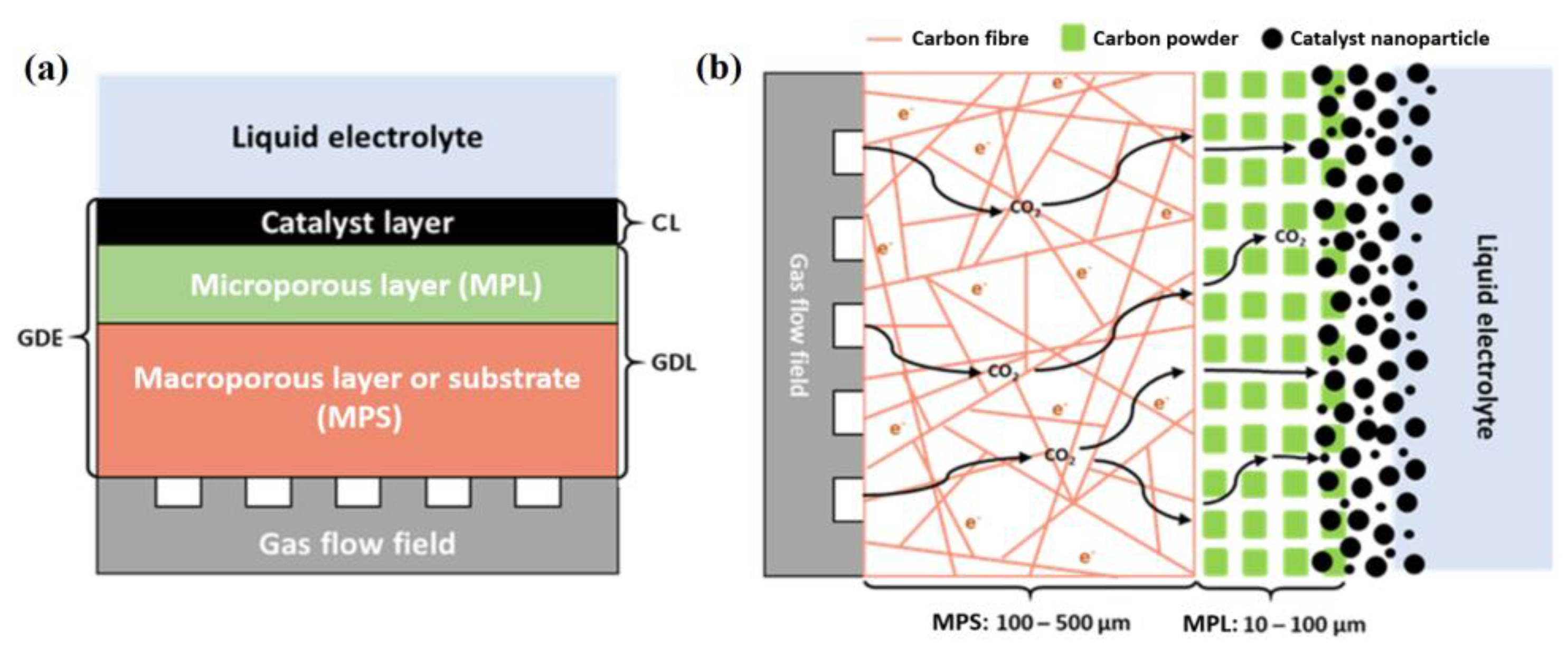
2. Gas Diffusion Electrodes

A gas diffusion electrode (GDE) consists of a gas diffusion layer (GDL) bearing a catalyst layer (CL) on its surface (Figure 1). In principle, GDEs can hold many types of catalysts, including metal, metal-free, and molecular catalysts, but also enzymes and microbes [22,23,24]. The GDL is a porous structured sandwiched between the catalyst layer and the gas flow channel or field. The GDL serves two primary purposes: it allows gas transport towards the catalyst layer and provides physical support to the catalyst. The GDL is hydrophobic, preventing the electrolyte from blocking its pores and facilitating gas transport to the CL. GDLs can be grouped into two main categories: single-layer and dual-layer GDLs. A single-layer GDL consists of just a macroporous layer or substrate (MPS), while in a dual-layer GDL an MPS is combined with a microporous layer (MPL). Dual-layer GDLs are most frequently used, especially in CO2 electrolysers to suppress the electrolyte flooding of the GDE. Figure 1 shows the typical structure of a dual-layer GDE. The gas flow field is in direct contact with the macroporous layer, acting as a gas diffuser and current collector. The microporous layer is located on top of the MPS and often consists of carbon and hydrophobic agents to regulate catholyte flooding.

2.1. Macroporous Layer or Support (MPS)

The MPS is usually made of carbon typically in the form of carbon-fibre paper, carbon cloth, carbon felt, or carbon foam [25]. Carbon is commonly used as a macroporous material due to its high stability in acidic environments, high gas permeability, good electronic conductivity, elasticity under compression, and tunable porosity [26,27]. The thickness of the macroporous layer is typically between 100 and 500 μm, with thinner layers better suited for gas transport.
Carbon-fibre paper is widely used as a substrate in CO2R GDEs. The manufacturing of carbon fibres is tailored to the application, whereby producers use different production methods to deliver required specifications. In general, carbon-fibre paper is graphitised at high temperatures (>2000 °C) enhancing electronic conductivity and mechanical strength, to be then impregnated with thermoset resin [28]. Hydrophobic treatments of the carbon paper surface control the wettability of the MPS. Various hydrophobic additives can be used, such as polytetrafluoroethylene (PTFE), polyvinylidene fluoride (PVDF), and fluorinated ethylene propylene (FEP) [29,30,31]. The addition of the hydrophobic agents is performed in multiple ways: dipping, spraying, or brushing, with dipping the more employed method. The resulting hydrophobicity is dependent on the concentration of agent present in the dipping solution and the dipping time. The effect of PTFE on performance has been studied in detail. High loadings of PTFE in the MPS makes the GDL less prone to electrolyte saturation but also leads to reduced gas transport and high electrical resistance [32,33]. The fabrication of custom-made MPS can improve the CO2 electrolyser performance; it is good practice to prepare and test MPS with various amounts of PTFE to find the optimum loading. This is a common approach in the optimisation of PEM hydrogen fuel cells, showing satisfactory results [25].
Apart from carbon-based MPS, metal-based GDLs also exist, such as metal mesh, metal foam, and micromachined metal. These have been extensively investigated in PEM fuel cells due to their excellent mechanical strength and good stability [34,35]. Inspired by a similar concept, Züttel and co-workers proposed a self-supported metal-based gas diffusion electrode for CO2 electrochemical reduction [36]. The innovative GDE was based on the porous structure of a catalyst made of zinc metal electrodeposited onto Cu mesh. The porous structure was immersed in PTFE, providing a hydrophobic coating. Afterwards, a layer of carbon black and PTFE mixture was sprayed onto the gas side of the GDE to prevent electrode flooding. Finally, the PTFE was soft-annealed to improve the hydrophobicity of the GDE.

2.2. Microporous Layer (MPL)

The MPL contains a thin layer of carbon black powder combined with a hydrophobic agent, typically PTFE. The MPL improves both electrical conductivity and water management [37,38,39]. It can also reduce the electrical contact resistance between CL and MPS, forming a flat and uniform layer impermeable to catalyst nanoparticles. The catalyst is applied to the MPL via drop-casting, airbrushing, electrodeposition, compression, or incorporation into the porous layer itself [40]. The MPL is capable of suppressing electrolyte flooding, lowering water saturation at the interface between the MPL and MPS and between CL and MPL. Unlike the MPS, hydrophobic agents are not applied on the MPL surface; instead, they are blended with the carbon powder [41]. Carbon powder is mixed with PTFE dispersed in water, organic solvent, and additives, creating a carbon ink [42]. The carbon ink is deposited onto one side of the MPS and heated to remove any residual solvents and surfactants and to induce PTFE flowing in the MPL. Extensive optimisation work has been carried out for MPLs applied in PEM fuel cells, looking at the effect of carbon type, carbon thickness, porous structure, and wettability, leading to important observations [43,44,45,46]. For example, the type of carbon affects the pore structure and wettability, impacting on the mass transport efficiency and electrical conductivity of the resulting GDE [47]. Moreover, high concentrations of PTFE in the MPL translate into lower pore volumes and therefore, worse performance [48]. It was also found that the thickness of the MPL has a significant influence on cell operation. A very thin MPL does not provide a smooth surface on the carbon cloth, resulting in higher ohmic resistance, but a thicker MPL leads to mass transfer limitations due to lengthened diffusion paths [49,50,51]. MPL optimisation not only plays a key role in hydrogen fuel cells but also in the improvement of CO2 electrolysers [52,53]. However, the factors affecting MPLs have investigated mainly for hydrogen PEMs and should be studied for CO2R. Although little work has been done in this regard, the influence of PTFE loading in the MPL of CO2 GDEs has been investigated, where a loading of 20 wt % was found to be optimum. This matter is discussed in further detail later in Section 5.1 of this review.

3. Aqueous-Fed and Gas-Fed Electrolysers

The ideal CO2 electrolyser will deliver high faradaic efficiency (FE, selectivity towards a specific CO2-derived product) and high current density (fast CO2-to-product conversion)—which is something not just desirable but essential to make the process industrially viable. Carbon dioxide electrolysers can be classified into two main groups: aqueous-fed electrolysers and gas-fed electrolysers. Aqueous-fed electrolysers are also called liquid-phase reactors; they convert CO2 solubilised and transported to the catalyst via the electrolytic solution (Figure 2a). Instead, in gas-fed electrolysers, the CO2 is introduced and brought in gas form as close as possible to the catalyst layer (Figure 2b). Aqueous-fed electrolysers are vastly used in research laboratories, leading to many published scientific papers [9,24,54,55,56,57]. This extensive use is a result of their ease of operation and adaptability to multiple types of electrode materials and configurations, making them ideal for the rapid and cost-effective study of CO2R catalysts. Although aqueous-fed electrolysers can provide critical information on key factors affecting CO2R—such as catalyst composition, structure, surface tailoring, and electrolysis environment—their commercialisation is inconceivable since industrial application is only viable at high conversion rates, i.e., current densities above 250 mA/cm2. Aqueous-fed electrolysers cannot fulfil this requirement due to limited CO2 mass transport restricting current densities to values up to 35 mA/cm2, for two-electron reduction processes in bulk liquid phase [58,59]. In particular, CO2R kinetics in batch-type electrolysis is limited by the slow diffusion and low solubility of CO2 in the aqueous media. In batch-type electrolysis (H-cell), even nanostructured catalysts act as planar electrodes, relying on the diffusion of CO2 molecules across multiple micrometre lengths to reach the catalyst [58]. Therefore, CO2R research is often carried out under various degrees of mass transport limitation, also leading to concentration polarisation. Consequently, true catalytic activities are difficult to estimate.
Although the diffusion limitations found in the batch-type aqueous-fed electrolysers can be overcome using flow cells to a certain extent, the poor solubility of the CO2 in aqueous electrolyte compromises the mass transfer and thus the current density [60]. The solubility of CO2 in aqueous electrolyte is 33 mM at 298 K and 1 atm [61]. The amount of dissolved CO2 can be increased using higher pressures and lower temperatures [62], which are options that are not commercially desirable and do not necessarily translate into higher current densities. Moreover, in the case of electrodes with porosity depths of several microns, only the outermost part of the catalyst reacts with CO2 under a diffusion-limited regime. On the contrary, gas-fed electrolysers do not present such mass transfer limitations being able to sustain current densities often higher than 200 mA/cm2 [58]. In gas-fed systems, CO2 is introduced in the reactor using gas diffusion electrodes. The purpose of the GDE is to facilitate the transport of CO2 to the catalyst layer. CO2 is fed from the gas side of the GDE through the GDL (Figure 1), establishing a gas/liquid (CO2/electrolyte) interface at the catalyst layer (Figure 2b). In principle, the interface can be positioned as close as possible or even beyond the CL. This allows establishing a high CO2 concentration gradient at the CO2/electrolyte interface, driving the rapid transport of CO2 to the catalyst. Thus, notoriously higher electrochemically active surface areas are obtained in gas-fed systems, where most of the catalyst is in active contact with CO2 thanks to shorter diffusion pathways (50 nm). The larger catalytic surface area for CO2R may result in higher geometric current densities and at lower overpotentials in comparison to aqueous-fed electrolysers [24]. Moreover, the gaseous products formed can easily diffuse towards the gas flow chamber before suffering any nucleation at the catalyst surface, avoiding blockages on active sites.
Evidence of high performance is apparent in the literature, where higher CO2 reduction rates have been consistently reported for GDEs. Since the early work by Cook et al. in 1990 [63] to the more recent one by Dinh et al.—delivering current densities of 1 A/cm2 and CO2-to-ethylene faradaic conversion efficiencies over 70% [64]—GDEs have systematically achieved industrially relevant CO2 conversion performance. Figure 3 shows this trend, where faradaic efficiencies versus partial current densities for different CO2R products in aqueous-fed and gas-fed electrolysers are compared. The performance of gas-fed electrolysers (full symbols) is consistently higher than that of aqueous-fed electrolysers (empty symbols). Although these data refer to different cell designs and catalyst configurations, the comparison shows the advantage of using gas-fed instead of aqueous-fed electrolysers, boosting higher current densities while retaining similar selectivity.
It is worth mentioning that high CO2R current densities often require high cell potentials, which is economically undesirable [19,100]. However, when very high current densities are obtained, e.g., in the range of A/cm2, considerable CO2 conversion is also achievable is diluted CO2 streams. This is essential for electrolyser scale-up where catalyst areas can be as large as 100 cm2. In this case, the need to obtain enough high single-pass conversion efficiencies will require the partial pressure of CO2 to decrease significantly through the electrolyser. Consequently, the catalysts should be active in diluted streams, especially at the outlet of the gas compartment where ideally the amount of unreacted CO2 left in the outflow should be as low as possible. Then, a catalytic system should achieve very high current densities in 100% CO2, in order to deliver useful current densities in real industrial settings [58].

4. Carbon Dioxide Electrolysers

Remarkable progress has been made in the study of CO2 electroconversion with thousands of scientific papers published to date [101,102]. However, there is still much to understand and do to make CO2 electrolysis industrially viable [103]. CO2R suffers from high over-potential, low current density, low product selectivity, and limited stability. To address these issues, research has primarily focused on the development of new and improved electrocatalytic materials, looking at composition, morphology, structure, surface state, nanoparticle size, etc. However, materials design is only one of the factors that influence CO2R. Operating conditions ought to be considered too, especially reactor design [104,105]. To date, comparably limited research has been carried out on the optimisation of CO2 electrochemical reactors, and even less work has attempted to integrate the many new catalysts developed by the materials research community. The impact of operating conditions is extremely important, and catalysts should be tested at least in industrial relevant conditions when access to industrial environments is not possible. From the reviews recently published on electrochemical reactor or cell design, it is clear that reactors determine current density, faradaic efficiency, and operational stability [60,106,107,108]. Reactor optimisation leads to higher conversion rates and energy efficiency, as a result of enhanced mass transport, lower ohmic resistance, and lower cell potential. In this section, we summarise the most common electrolytic reactors focusing in particular on gas-fed electrolysers where gas diffusion electrodes are employed. Since the foundational work of Hori et al. in the 1980s [109], different CO2 reactor designs have been proposed. In general terms, reactors can be classified into two main groups: H-cell and flow cell. In this review, lab-scale and pilot-scale reactors will be discussed, providing a broad overview.

4.1. H-Cell Reactors

The H-type cell is the most known and used lab-scale CO2R reactor. Figure 4 shows a simplified schematic diagram of a conventional H-type electrochemical cell. The working electrode (WE) and reference electrode (RE) are located in the cathodic compartment, while the counter electrode (CE) is placed in the anodic one. The two compartments, also called sections or chambers, are typically connected through a channel separated by an ion-exchange membrane. This set-up provides the characteristic “H” shape, hence the name of the cell. The working electrode can be a bulk catalyst, such as copper foil, or a nanostructured catalyst; copper is particularly amenable to nanostructuring and integration in composites [110,111,112]. Carbon dioxide is typically introduced in the cathodic chamber via a capillary tube or a glass frit, the latter sparging smaller bubbles on the working electrode. Larger bubbles are detrimental to CO2R, since they limit the amount of electrolyte in contact with the WE. The depletion of electrolyte, and thus of dissolved CO2 available for electroreduction, translates into a decrease in CO2-derived gaseous products at the advantage of hydrogen evolution reaction (HER) [108]. Therefore, the use of a glass frit is frequently preferred, although it does not necessarily solve the possible build-up of stagnant bubbles. A mass flow controller is typically employed to regulate the CO2 flow in the catholyte.
The electrochemical cell should be gastight to allow the accurate collection of gas samples at the outlet. The composition of the gas samples is commonly determined with a gas chromatographer (GC), from which to calculate the faradic efficiencies of gas products. Liquid products in the electrolyte can instead be identified and quantified using proton nuclear magnetic resonance (NMR) or high-performance liquid chromatography (HPLC). The H-cell is a batch reactor for lab-scale CO2 electrolysis studies. It suffers from mass transport limitations and high cell electrical resistance, both compromising the evaluation of true catalyst performance, considering “true” the performance observed on a larger scale. Another major issue of H-cell reactors is the low CO2 conversion efficiency. Only a minuscule amount of the CO2 fed in the reactor is converted to products; consequently, the gas products are diluted in a stream of unreacted CO2.

4.2. Flow Cell Reactors

In flow cell reactors, the electrolyte is in a continuous flow. Often both catholyte and anolyte are pumped and refreshed, although sometimes the anolyte might be static [106]. Flow reactors have several advantages compared to batch reactors: they increase mass transfer and improve mixing, provide better temperature and heat management, and exhibit a precise control of the electrolyte residence time in the reaction chamber [60]. It is worth noting that the performance of CO2 catalysts in batch experiments do not apply to flow regimes given the impact of mass transport on product selectivity. Therefore catalysts, whose CO2 conversion performance has already been tested in batch cells, should be retested in flow cells.
Unlike batch reactors, where most of electrolysis have been carried out using a three-electrode configuration, in flow reactors, other configurations are also common. Some flow reactors use a two-electrode configuration with WE and CE—cathode and anode, respectively—but no RE; thus, no control or monitoring of the WE potential is possible. Other flow electrolysers use a three-electrode configuration with a RE placed in the cathodic compartment; in such a configuration, the WE potential can be monitored. Rarely, a four-electrode configuration, with two reference electrodes, is used. This system is beneficial when anodic reactions additional or alternative to water oxidation are present at the CE, and the electrode potential of both half-cells needs to be monitored [113].
CO2 electrochemical flow reactors can be grouped into four categories: (1) basic flow, (2) polymer electrolyte membrane, (3) microfluidic, and (4) solid-oxide electrolysers. Solid-oxide electrolysers are important but outside the remit of this review, since they follow different operational conditions and principles. Readers interested in CO2 solid-oxide electrolysers are directed to these reviews [114,115].

4.2.1. Basic Gas-Fed Flow Electrolysers

We introduce here the terminology “basic” electrolyser to denote a basic design from which other electrolyser configurations can be derived. It is essential to mention that terminology varies among published work. Sometimes, CO2 gas-fed electrolysers have been named “liquid-phase” electrolysers, since the catalyst was in contact with aqueous electrolyte. To avoid confusion, in this work, liquid-phase or aqueous-phase electrolysers are those in which CO2 is primarily delivered to the catalyst as carbon dioxide dissolved in the electrolyte. Thus, some of the previously named “liquid-phase” electrolysers are considered here “gas-fed” electrolysers, since CO2 was delivered to the catalyst in gaseous form. Figure 5 shows the schematic and operating principle of a basic gas-fed flow electrolyser. The cell consists of three different compartments. The first compartment, from left to right, is filled with CO2 gas, the second is filled with catholyte, and the third is filled with anolyte. The anodic and cathodic compartments are separated by an ion-exchange membrane. The membrane serves multiple purposes. First, CO2R products should not cross the membrane to be oxidised at the anode. Second, O2 evolving from the anode should not enter the cathode compartment to be reduced back to water. These are typically cation-exchange or anion-exchange membranes, depending on the product of interest and working conditions. In particular, membranes transporting ions of opposite charge to the ionic product of CO2 conversion should avoid product crossover and loss [116,117]. For example, cation-exchange membranes would, in principle, be a better option for anionic species such as formate, although not all experimental evidence support this approach [118]. Usually, anolyte and catholyte are circulated using two separate pumps, ensuring a constant flow of electrolyte in both compartments. The CO2 and cathodic compartments are separated by a GDE. The catalyst present on the GDE is in contact with the catholyte on the cathodic side, while CO2 gas is fed from the back of the GDE. Conductors such as carbon nanotubes (CNTs) can be incorporated into the catalyst layer as a support for the additive to provide or improve electrical transport, as shown in some entries of Table 1.
The basic gas-fed flow reactor is broadly used in CO2 electrolysis, achieving high current densities for CO, formate, hydrocarbons, and oxygenates. The cell allows the precise control and optimisation of the reaction environment [117]. Table 1 lists some examples of basic gas-fed flow electrolysers applied to CO2R using various catalysts. High faradaic efficiencies and current densities demonstrate the potential of this cell design for industry application, overcoming the mass-transport limitations seen for H-cell reactors. However, cell design is not the only factor that affects CO2R performance; the way CO2 gas is supplied to the catalyst is also crucial.
Two main configurations are possible for CO2 gas to reach the catalyst layer: flow-by and flow-through [133]. As shown in Figure 6, in the flow-by configuration, CO2 flows alongside the GDE and eventually reaches the catalyst layer by diffusion. In the beginning, CO2 gas enters the pores of the GDL. Once the entire depth of the GDL is filled, the CO2 comes into contact with the catalyst surface, where it is adsorbed and reduced to products. The products desorb and diffuse back through the GDL into the CO2 stream (gas products) or as they move in the opposite direction into the electrolyte (liquid products). A thin CO2 diffusion layer is established, resulting in high CO2 mass transport as the concentration difference between the inside and outside the GDE is large.
With the progress of the electrolysis, far from the CO2 inlet, the concentration of CO2 will start decreasing as the product concentrations increases. It is essential to highlight that for this process to work, the electrolyte must be in continuous contact with the GDE. Then, flooding the GDE with electrolyte is a major issue of the flow-by configuration. Often due to electrowetting, i.e., change of wetting properties with applied potential, the catholyte enters and fills the porosity of the GDL flattening the concentration gradient and slowing the diffusion of CO2 to the catalyst [134]. However, flooding can at times be advantageous when the crystallisation of electrolyte in the GDL is an issue. Furthermore, since in flow-by mode CO2R is substantially governed by diffusion, competitive H2 evolution (i.e., proton reduction instead of carbon dioxide reduction) can also affect the performance of the electrolyser. Alternatively, in the flow-through configuration, the CO2 gas is forced to flow through the entire depth of the GDE. Therefore, no concentration gradients are formed. Nevertheless, this configuration causes the formation of gas bubbles in the catholyte, resulting in a high ohmic drop. Furthermore, electrolyte salt precipitation inside the GDE is a possible problem, blocking the GDE over time. Running an electrolyser in either of the configurations is mainly a matter of differential pressure across the GDE. The challenge of balancing this pressure differential and operating both flow-by and flow-through modes are explained further in Section 5.4 of this review.

4.2.2. Polymer Electrolyte Membrane Electrolysers

Polymer electrolyte membrane (PEM) electrolysers, sometimes called membrane electrode assembly (MEA) electrolysers, are also used in CO2R. This design is similar to that of a proton exchange membrane fuel cell (PEMFC), where both cathodic and anodic compartments include a GDE, current collector, and flow plate. The catalyst layer of each GDE is in contact with an ion-exchange membrane sandwiched between the two electrodes (Figure 7). Given that there is no separation between electrodes and membrane, this type of configuration is also called zero-gap. This type of electrolyser can be seen as an evolution of the basic gas-fed configuration, where in this case, a GDE is used in each compartment, and the cell operates without liquid electrolyte. PEM electrolysers overcome issues of limited CO2 solubility since there is no liquid electrolyte present. Instead, the membrane works as a solid-state electrolyte supporting ion transport between the electrodes. Gaseous reactants and products flow in and out of the reactor with the electrodes located in close proximity to each other, decreasing the cell resistance. The reactants are typically humidified, since no aqueous electrolyte is present [135]. In its simplest form, H2O required for CO2 reduction is provided by bubbling CO2 through a water column.
In contrast with other reactors, no reference electrode is employed in PEM electrolysers, using only working and counter electrodes [108]. Consequently, CO2R is carried out by controlling cell voltage (or current) rather than the independent control of the working electrode potential. This can make the study of the CO2R cathodic process difficult to disentangle from the corresponding anodic process. The proximity of the electrodes is arguably one of the main advantages of membrane-separated zero-gap reactors, but ironically, it is also one of the main disadvantages. Finite ion transport rates across the membrane can induce significant pH imbalance between catholyte and anolyte. For example, this is an issue when catholyte acidification increases H2 evolution at the expense of CO2 reduction [106]. Another major issue of PEM electrolysers is the drying of the ion exchange membrane with a detrimental effect on the ion transport capabilities [135].
Table 2 is a summary of various studies completed with CO2 PEM electrolysers. Experiments were conducted using different cell conditions and ion exchange membranes. The ion-exchange membrane is a critical component in the overall performance of a PEM electrolyser. Each type of membrane leads to specific ion transport pathways between anode and cathode. In principle, the membrane should prevent cross-contamination and the mixing of products while allowing current flow. The transport of ions has been thoroughly analysed in various membranes for water electrolysis, but less information is available for CO2 electrolysis [136]. Polymer electrolyte membranes are classified into three types: cation-exchange membranes (CEMs), anion-exchange membranes (AEMs), and bipolar membranes (BPMs) [60]. Understanding the properties of membranes and their effect on CO2 reduction is vital to the improvement of CO2 PEM electrolysers [137]. For example, the effect of the type and concentration of functional groups, and the thickness and ionic conductivity are important parameters to be considered in developing or selecting a membrane. Most CO2R studies with PEM electrolysers have been performed using CEMs. In this configuration, protons or other cations move across the membrane from anode to cathode. Then, the CO2R product selectivity depends on the efficiency of proton transport across the membrane; products that require fewer protons to form are favoured when underperforming proton transport membranes are used [138]. AEMs operate by mediating the flow of anions, such as OH, from cathode to anode, regulating proton transfer and promoting CO2 reduction [108,139]. Unlike CEMs, in AEMs, water dissociation, from a humidified gas stream, provides the protons for CO2R. Due to the lower proton availability, usually less HER is observed in AEM systems. However, under basic conditions (high hydroxide concentration), bicarbonate and carbonate anions are formed and transported to the anode. These anions inhibit membrane ion transport because of their lower mobilities and hinder the CO2R, since CO2 is transported away from the cathode [60].
In the absence of electrolyte, and in particular, of catholyte to provide the local environment necessary for the CO2R reactions to occur, the type of membrane impacts massively on the CO2 conversion process. For example, Masel and co-workers used an N-methylimidazolium-substituted styrenic copolymer membrane (commercially available as Sustainion®) to improve carbonate ion transport, enhancing the CO2R and resulting in outstanding cell stability (4380 h) [141]. Aeshala et al. have also reported improved CO2R efficiency using solid polymer electrolytes based on quaternary ammonium groups [137]. Moreover, it has been recently proposed that encapsulation of the catalyst in different types of polymers may influence on the CO2R selectivity and stability, relying upon the polymer nature [153].

4.2.3. Microfluidic Electrolysers

A microfluidic cell for the conversion of CO2 to formic acid was first proposed by Kenis and co-workers [154]. Since then, microfluidic reactors have been applied to CO2R using several catalysts under different operating conditions. A simplified schematic of a microfluidic reactor is given in Figure 8. In this design, two GDEs, cathode and anode, are separated by a very thin layer (<1 mm) of flowing liquid electrolyte [108]. CO2 gas is supplied from the rear of the cathode reaching the catalyst layer through GDE, while oxygen is released directly into the air on the anodic side. Unlike the other reactors, this design works without a membrane, relying on the diffusion of the gaseous products to divide reduction and oxidation products [60]. Nonetheless, CO2 reduction products might be oxidised at the anode, and accordingly, products should be driven out of the electrolyser with a rapid flow stream. The electrolyte flow can be adjusted to modify the operation conditions, including pH and water management issues, such as flooding or dry-out [108]. A reference electrode can be placed in the electrolyte, letting the measurement of individual electrode potentials. There are also examples of microfluidic cell using membranes, in particular one for the electrosynthesis of ethylene and ethanol from CO2 [155].
Table 3 is a summary of different studies carried out using microfluidic electrolysers with and without a membrane. The same type of GDL was employed in most of these studies, highlighting the opportunity to test other GDLs. The porosity of the GDL affects the selectivity and activity of CO2R by only 1%; whereas, channel length and gas flow rate appear to play a central role in determining the performance of microfluidic cells [108]. Microfluidic reactors are well suited to work with strong alkaline electrolytes known to facilitate the conversion of CO2 to multi-carbon products. However, the scale-up is challenging due to the pressure sensitivity of the microfluidic architecture, limiting their potential industrialisation [156].

4.2.4. Comparison of Reactor Configurations

PEM electrolysers present certain intrinsic advantages in comparison to other flow reactors where a liquid-phase electrolyte is employed. Reactor design is more straightforward in PEM cells, involving fewer auxiliary components for electrolyte circulation. Moreover, no other mobile counterions are substantially present in PEM systems apart from proton and hydroxide ions, improving CO2 utilisation. From a safety point of view, PEM electrolysers do not require corrosive liquids, avoiding the risk of leaks or heat-induced pressure build-up [24]. They also allow operating at higher pressures with differential pressures between the electrodes, as reactant crossover is suppressed [163]. Finally, PEM electrolysers enable the separation of volatile liquid products, avoiding the formation of product/water mixtures [164]. Considering these multiple advantages and the low cell resistance of PEM reactors, it is foreseeable that these type of electrolysers will lead the way towards the best CO2R performance [107]. However, similar CO2R efficiencies, if not better, were also achieved with basic flow-cell reactors, especially in the formation of C2+ products, where fewer experimental studies with PEM reactors have been published. Moreover, it still is a challenge to operate a PEM electrolyser for C2+ products at high current densities and high selectivities. These obstacles may be related with having enough water molecules in the cell for C2+ products to form.
The ideal design of CO2 electrolysers is yet unclear, as each cell reactor presents advantages and disadvantages. It is essential to optimise reactors that have already been proposed while proposing new designs. In principle, the optimisation of PEM electrolysers seems feasible, but limited knowledge of membrane resistance, stability, and cost (adding to the aforementioned water issue) is delaying their scale-up. Improving membrane performance and better control of catalyst wetting are critical steps towards the application of CO2 PEM electrolysers. Basic flow-cell reactors are affected by limitations, too. Remarkable CO2R performance has been obtained with basic flow-electrolysers in past experiments, but catholyte carbonation, flooding of GDE, and limited stability still hinder their scale-up and industrialisation.

4.2.5. The Role of Phases in Reactor Operation

The underlining design principle of all flow cell reactors discussed to this point (basic gas-fed flow electrolysers, polymer electrolyte membrane electrolysers, and microfluidic electrolysers) is the efficient transport of CO2 to the catalyst layer. A key factor affecting the availability of CO2 in all designs is the role of phases and related phase boundaries (solid/liquid/gas, catalyst/electrolyte/CO2) established at the catalytic active sites and what phases must coexist for CO2R to proceed.
Originally, CO2 reduction at gas diffusion electrodes was considered a three-phase interface process, considering that CO2 conversion took place at the gas–liquid–solid interface of CO2, electrolyte, and catalyst, respectively [63]. No explicit evidence was provided in support of this theory, but since then, it has been referenced in various research papers [135,165,166,167]. Burdyny et al. have recently proposed a different perspective in support of a two-phase reaction interface involving dissolved CO2 as the reagent [58]. They proposed that a thin film of water always surrounds the catalyst, even near the gas–liquid interface, considering the hydrophilic inclination of metals under applied reductive potential (Figure 9). Furthermore, stable CO2 reduction can be maintained even in flooded GDEs, which is something that would be inconceivable if the process required a three-phase interface.
Weng et al. also supported the hypothesis of a two-phase reaction interface, stating that the catalyst needs to be covered with electrolyte in order to be active [168]. They backed this idea since previous experimental and theoretical studies demonstrated the role of water and hydrated cations in the basic process of CO2R [169,170]. Therefore, they proposed that a porous catalyst layer can be either dry, partially wet, or flooded, and the performance of the GDE depends upon the environment within the CL. Dry pores are inactive due to the absence of water and lack of ionic pathways. Flooded pores block the gas channels within the CL, leading to high mass-transport resistance for the CO2 reactant. A wet layer delivers the best performance, but it should be thin enough to enhance CO2 mass transport yet sufficiently thick to provide ionic conductivity within the CL.
The fraction of pores flooded during operation can be linked to the capillary forces acting on the electrolyte. Low capillary forces result in the flooding of small hydrophilic pores only, whereas large capillary forces cause the flooding of most of the pores. However, Burdyny et al. consider that the catalyst pores lead to high capillary forces causing the wetting of surfaces, rather than a partially wet situation [58]. Notwithstanding, there is evidence that CO2R reactions occur at a two-phase interface, where CO2 must be dissolved in the electrolyte in order to be reduced, even when CO2 is supplied in gas phase to the CL. More research is needed to clarify the two-phase mechanism, since its impact on the cell performance is evident. This is particularly important in PEM electrolysers where the wetting of the CL is dependent on the condensation of the water carried by the humidified CO2 stream. Besides, the lack of water could promote H2 evolution over CO2R through the direct reduction of the protons dispatched by the ion-exchange membrane. Hence, it is essential to increase the amount of water available in PEM electrolysers, either through adding water, increasing the humidification of the CO2 stream, or enhancing water transport through the polymer membrane.

5. Failures and Challenges in CO2 Flow Electrolysers

The importance of adopting gas-fed electrolysers to achieve the selectivities and high current densities critical for the scale-up of CO2 electrolysis has been repeatedly emphasised in this review. Along with gas-fed electrolysers, gas diffusion electrodes must be developed, too. In particular, the physical and chemical phenomena underpinning the operation of both need to be investigated and better understood. The intimate and intricate link between the stable operation of electrolysers and the effect of electrode structure, components, and stability for different flow configurations has to be unravelled to deliver the best CO2R performance. In order to succeed in this endeavour, it is crucial to identify failures or deficiencies and point out opportunities for improvement for all key factors affecting CO2 electrolysis.

5.1. Components of Gas Diffusion Electrodes

A critical point in the advancement of CO2 gas-fed flow electrolysis lies in the development of GDEs tailored for CO2 reduction. Currently, GDEs are repurposed from PEMFC systems engineered for H2 instead of CO2 electrochemistry [171]. GDEs from PEM fuel cells might not be adequate for CO2R cells, especially considering that product selectivity is not an issue in water electrolysis. In PEMFC, GDLs provide gas, liquid, electron, and heat transport in the presence of water; thus, their material composition and microstructures are adapted to it [172]. In particular, MPLs are designed for the removal of water from hydrogen fuel cells, mostly at high current densities when copious water can hinder oxygen influx [173,174]. This is in contrast with having to provide (not remove) water to CO2 reduction, as previously discussed. GDLs used in hydrogen fuel cell have certain properties suitable for CO2 reduction, such as geometry, permeability, and electrical conductivity, but they do not fulfill other requirements, such as stability at high cathodic potentials specially avoiding flooding (electrowetting). Gas-fed systems for CO2 utilisation are intrinsically more complex, being dependent on interrelated and contrasting processes coexisting in the three-dimensional structure of the GDE. Exemplary is the delivery of enough water for CO2 conversion without swamping the electrode. The study of this and other factors is imperative not only for a better understanding of CO2R in GDEs but also to improve the operational stability of CO2 electrolysers.
Numerous studies have endeavoured to identify the subtle links between different GDE design parameters. The CO2R reaction rate is dependent on the thickness and hydrophobicity of the macroporous layer, predetermining the CO2 mass transport resistance in the GDE [175]. Kim et al. considered the impact of the thickness of an Ag-based GDE macroporous layer on CO2R performance [52]. They observed worse CO2 permeability in thick MPS (370 µm), and thus lower CO partial current densities compared to those recorded with thinner carbon–fibre substrates (190 µm). Nevertheless, very thin MPS (110 µm) lead to electrode flooding. So, optimal MPS thickness is essential to facilitate gas permeability while limiting flooding. The concentration of hydrophobic agent in the MPS has also a major impact on CO2 electrolysis. Ikeda et al. recorded similar CO2R reaction rates for MPS containing 10 to 30 wt % PTFE, but worsened performance using quantities above 30 wt % PTFE due to a decrease in the electrical conductivity [176]. Besides the MPS, the MPL play a significant role in CO2 electrochemical conversion as reported by Kenis and co-workers [52]. The MPL provides catalyst support while preventing flooding and protects the MPS from the electrolyte, suppressing HER and consequently improving the current density of CO2R.
The amount of PTFE present in the MPL is also important. PTFE content in the range of 4.5–10 wt % does not prevent flooding nor provides a binding between carbon and catalyst layer, resulting in higher HER and lower cathode stability [52]. PTFE concentrations higher than 20 wt % reduce the porosity of the MPL and affect the electrical conductivity of the GDE. Similar research was conducted by Li et al., showing that the highest current densities for CO production were obtained using a PTFE loading of 20 wt % [177]. A different approach was taken by Wang et al., where the performance of gas diffusion electrode for CO2R to formate was enhanced by adding PTFE directly into the catalyst layer [53]. There remain many options to be explored, providing a plethora of opportunities to the CO2 reduction research community.

5.2. Stability and Degradation of Electrolyser Components

CO2R systems need to match the lifetime of PEM water-splitting electrolysers (beyond 20,000 h), as highlighted in a recent techno-economic analysis by Jouny et al. [100]. The current best performance tops to less than 5000 h (Table 2). The same study also noted the importance of long-term durability in cutting maintenance and replacement costs. Although durability is critical to the industrialisation of the CO2 electrolyser, the majority of experiments published in 2013–2019 are limited to stability studies of 30 h or less [135]. The limited stability of CO2R cells stems from multiple degradation mechanisms occurring during operation. There are several mechanisms from catalyst poisoning, caused by contaminants present in the electrolyte, to the oxidation of cell and electrode components. Certain catalyst materials and anode compartments can suffer electrochemical oxidation when exposed to potentials above their standard oxidation potential. The rate of oxidation depends on the materials employed, the electrolyte concentration, and the pH. Pourbaix diagrams may be useful to researchers to find information about the stability of their catalyst particles at defined pH and applied potentials [178,179]. Detectable oxidation is observed during long electrolysis, typically after several hours depending on the materials employed. An example of such oxidation has been reported by Yang et al., where during CO2 conversion to formate, clear evidence of oxidative degradation of the carbon anodic flow field was found [91]. Physical degradation is also visible during the CO2R process, inducing structural changes in the catalyst particles and consequently in the GDEs. This type of degradation includes the agglomeration or pulverisation of the catalyst particles impacting on the uniform distribution of particles in the electrode. Chemical degradation involves the adsorption of undesired species onto the catalyst surface. Poisoning can occur on the electrode during testing, where metal impurities present in the electrolyte adsorb on the catalyst, hindering CO2R [84]. Typically, poisoning can be reverted by desorbing the impurities. For example, Ikemiya et al. desorbed impurities by applying a positive current to the GDE in acidic electrolyte [180]. Apart from poisoning, the catalyst binder can also suffer from chemical degradation. Often, the catalyst is bonded to the electrode with a polymer binder; under alkaline conditions over extended operation times, fluorinated binders can degrade, leading to polymer degradation or side-chain modification [181]. Consequently, the catalyst can detach from the electrode during electrolysis. More degradation methods have been extensively explained in a recent review written by Kenis and co-workers, presenting durability testing performed by various research groups [135]. Here, we focus on the degradation mechanisms affecting gas diffusion electrodes. Understanding how a GDE responds and fails during long-term operation is essential to bolster CO2R electrolytic systems.
Five mechanisms of degradation have been reported for GDEs in PEM water electrolysers and hydrogen fuel cells: (1) mechanical compression during manufacturing, assembly, and operation, (2) freezing and thawing during operation, (3) dissolution in water, (4) erosion by gas flow, and (5) carbon corrosion [182,183]. Not all these mechanisms necessarily apply to CO2 electrolysers. For example, typically, CO2R systems operate at ambient temperature, such that wearing through freeze/thaw does not necessarily apply. The oxidative carbon corrosion of anodes is relevant for both water and CO2 electrolysers. Carbon present in the porous layers of GDEs could be oxidised and converted to CO2, resulting in a loss of material. The mechanical stress, erosion, and dissolution of electrode materials can instead affect the long-term operability of CO2 GDEs, so they should be taken into consideration. The erosion of GDEs by a continuous gas flow can affect hydrophobicity, leading to electrode flooding.
Besides these failure modes, CO2R systems face two specific intertwined issues: (1) electrolyte carbonation and (2) flow configuration, which are to be addressed in the following two sections.

5.3. Electrolyte Carbonation

Electrolyte carbonation occurs when dissolved CO2 reacts with hydroxide ions (OH) in alkaline electrolytes. This is a very well-known chemisorption reaction widely applied in the direct air capture of CO2 from the atmosphere [184]. Dissolved CO2 reacts with OH to form a bicarbonate ion (HCO3) (Equation (1)), which afterwards reacts with another OH to give a carbonate ion (CO32−) and water (Equation (2)).
CO2(aq) + OH(aq) HCO3(aq)
HCO3(aq) + OH(aq) CO32(aq) + H2O(aq)
Kinetic studies show that the deprotonation of bicarbonate to carbonate (Equation (2)) is faster than the formation of bicarbonate from CO2 (Equation (1)). Therefore, CO2 that reacts with OH is rapidly converted to CO32− [185].
The presence of OH in CO2R electrolyte is inevitable, as it is a by-product of the electrochemical reduction of CO2. Therefore, even though a neutral pH solution is used, a basification of local cathodic pH (around 12 at high current densities) will occur during the reduction process [133]. Consequently, the carbonation of dissolved CO2 in the electrolyte-wetted regions of the GDE is unavoidable. Carbonated CO2 is not available for electroreduction since CO2R requires dissolved CO2 as a reactant; neither bicarbonate nor carbonate ions are considered viable reactants for CO2R (Figure 9). On the other hand, alkaline catholytes have some beneficial effects on CO2R. A highly alkaline environment, such as concentrate potassium hydroxide, minimises the electrical resistance across the cell in comparison to neutral or slightly alkaline carbonate/bicarbonate solutions [186]. Moreover, the electrolyte pH has a key effect on the catalyst activity and selectivity towards certain products. Dinh et al. and Gabardo et al. have reported that higher pH results in lower overpotentials for CO2 conversion to CO and hydrocarbons [120,187]. Todorova et al. have summarised results from various experimental studies portraying facilitated C2 product (C2H4 and C2H5OH) formation in electrolytes with weak buffering capabilities, such as KCl, KClO4, and K2SO4, that allow an increase of local pH at the electrode/electrolyte interface during CO2R. Instead, buffers such as KHCO3 and K2H2PO4 promote the formation of CH4 and H2, as the electrolyte pH tends to be close to neutral [188].
At the start of the CO2R process, the loss of dissolved CO2 via carbonation is overcome as CO2 is gas-fed in stoichiometric excess to the reactor. Yet, the production of unwanted bicarbonate and carbonate induces a buffer neutralisation effect, decreasing the pH of the catholyte to neutral values [189]. Moreover, the galvanostatic (constant electric current) operation ensures that HER, also generating OH, will substitute for any lost CO2R within the CL. When the rate of CO2 electrolysis decreases, the high local pH owing to HER will further increase the carbonation rate, inducing a detrimental positive feedback loop [171]. This causes a cathodic drift when operating galvanostatically, which translates in an increase of the kinetic overpotential as a result of electrolyte neutralisation.
Although the complete elimination of the carbonation effect is not possible, its effect can be minimised. While the carbonation effect is notorious in batch reactors such as the H-cell where carbonate builds up in the catholyte, flow cell reactors reduce this effect as the electrolyte is circulated and refreshed. Consequently, with flow reactors, it is recommended to replenish the catholyte solution to reduce the impact of carbonation on the CO2R process.

5.4. Flow Configurations

As previously mentioned, CO2 gas flowing through a GDE can reach the catalyst layer in two ways or flow configurations: flow-by and flow-through. The differential pressure, ∆P, across the GDE determines the type of flow configuration governing the electrolyser. ∆P can be expressed as the difference between the catholyte pressure and gas pressure (∆P = Pcat − Pgas) acting at the front and back of the GDE, respectively. The value of ∆P controls the position of the plane of penetration of the electrolyte into the GDE (i.e., the gas–liquid interface), swinging the operation between two mutually excluding situations: one where the plane does not penetrate the GDE resulting in a dry electrode, and the other with the plane entirely pushed through the electrode in the gas compartment, resulting in a flooded electrode. Both situations present multiple challenges, since CO2 availability at the catalyst and gas transport in the electrode are very much dependent on the positioning of the gas–liquid interface in the GDE. In particular, when the plane of penetration is closer to the electrolyte side, electrolyte salt precipitation is observed in the pores of the electrode hindering gas transport; whereas, when the plane is pushed near to the gas side, the pores are blocked with liquid electrolyte, resulting again in hindered gas transport. These and other related phenomena are discussed in detail in the next two sections.

5.4.1. Challenges in Flow-Through Configuration

At negative differential pressures, ∆P < 0, gas will cross the GDE and CO2 bubbles will emerge in the catholyte, leading to the flow-through configuration [190]. The presence of gas bubbles increases the ohmic drop through the catholyte, lowering the energy efficiency of the electrolyser. Duarte et al. reported that bubbles in the electrolyte lead to an increase of 1.0 V in cell potential and an energy efficiency drop of 6.5% in comparison to the flow-by configuration [133]. Furthermore, bubbling through the GDE causes fluctuations of electric current and may be involved in the mechanical degradation of the catalyst layer over time [135]. Additionally, higher amounts of CO2 gas in the electrolyte solution might result in higher carbonation and thus catholyte neutralisation, affecting product selectivity.
Another challenge of the flow-through configuration is the formation of physical blockages within the GDE that hinder CO2 flow and promote HER. Crystal salt blockages have been reported upon the drying of electrolyte in the GDE. Electrolyte penetrates the GDE because of electrowetting effects. Electrowetting is the modification of the wetting property of a solid surface with an applied electric field [191]. GDEs are hydrophobic when immersed in the catholyte at open circuit potential, but increasing hydrophilicity is observed after passing a faradaic current, leading to GDE flooding [171]. As the electrolyser operates in flow-through mode, the electrolyte left inside the GDE is pushed towards the cathodic chamber. Some water evaporates in the process, forming salt crystals that obstruct gas flow to the catalyst [192]. Carbonation exacerbates the problem. As CO2 reacts with OH ions in the GDL, the precipitation of carbonate salts is also observed. KHCO3 and K2CO3 have lower solubilities, 3.62 mol/kg H2O and 8.03 mol/kg H2O, respectively, than KOH (21.57 mol/kg H2O) on a molar basis [186]. Therefore, under these circumstances, both bicarbonate and carbonate salts precipitate, generating crystals inside the pores of the GDL. Such crystals are visible on the back of the GDE, and they have been reported in many studies [88,133,135,143,171,190,193,194]. Moreover, carbonate salts can react with additional CO2 to create more bicarbonates, as shown in Equations (3) and (4) [171,195]:
K2CO31.5H2O(s) + CO2(g) 2 KHCO3(s) + 0.5 H2O(g)
K2CO3(s) + H2O(g) + CO2(g) 2 KHCO3(s).
The accumulation of salt inside the GDL is damaging, since CO2 mass transport to the catalyst layer is compromised, consequently decreasing productivity and selectivity. Leonard et al. have recently reported that the carbonation rate at the cathode increases with current density [171]. They found salt crystals deposited on the back of the GDE when high current densities were applied. This translated in lower water breakthrough pressures that decreased with increasing current densities, justifying the hygroscopic effect of the salts and leading to a loss of GDE hydrophobicity. Carbonate salts are hygroscopic, so any crystallites formed can promote water pumping through the MPL via capillary action [196], triggering a reinforcing loop process where dry electrolyte salt drives in more liquid electrolyte. This process impacts directly on CO2R selectivity. For a silver catalyst layer at high current densities (150 and 196 mA/cm2), it was found that the molar fraction of CO in the product mixture decreased dramatically in the first 30 min, shifting towards the H2 production [171]. Moreover, at higher current density, the capacitive current rapidly increased over time, implying changes at the electrode–electrolyte interface. Interestingly, the same study reported that the GDE was non-uniformly wetted, and flooding was augmented where the concentration of CO2 was higher, next to the gas inlet, corroborating the carbonation hypothesis [171].
Completely recovering the GDE performance after carbonation is not possible, or at least no such system has been reported yet. The poor recovery of GDEs used in flow-through configurations has been documented by a number of research groups [88,143,194]. Fully removing crystals that are deeply embedded in the porosity of a GDE is very challenging. Salt crystals can induce permanent structural damages to the GDE, increasing permeability and reducing hydrophobicity [171,197].

5.4.2. Challenges in Flow-By Configuration

An electrolyser is operated in flow-by mode when the differential pressure across the GDE is zero or positive, ∆P ≥ 0 [133]. Under these circumstances, the gas does not cross the GDE, and no bubbling of CO2 is observed in the catholyte. In flow-by configuration, CO2 enters in the pores of the GDE and reaches the catalyst layer through diffusion, leading to a concentration gradient. Small droplets of electrolyte are typically visible on the gas side of the GDE. The penetration or flow of catholyte towards the gas chamber through the GDE is named “perspiration”. Perspiration occurs mainly for two reasons: (1) changes in GDE hydrophobicity due to electrowetting, and (2) changes of differential pressure across the GDE. In addition, gas products resulting from CO2R could increase the internal pressure of the GDE, lowering its tightness and thus promoting perspiration [121]. Perspiration affects electrolyser performance. It prevents the precipitation of carbonate salts in the GDL, avoiding the blocking of CO2 pathways towards the catalyst [133]. Analyses of perspired solutions showed the presence of K2CO3 and KHCO3 and pH values of 10 [121]. This is advantageous as it inhibits permanent pore obstruction. However, the solution itself can block the porosity and slow the flow of CO2 in the GDE at the expense of reactor performance.
In general, when current is applied to the cell, small perspiration droplets appear on the back of the GDE. Over time, the droplets grow to coalesce and fall at the bottom of the gas chamber. Without an outlet to remove the perspired electrolyte, the gas compartment would eventually flood. Consequently, it is essential to discharge any electrolyte build-up. The perspired electrolyte is often redirected to the catholyte storage tank to recirculate afterwards. It is relevant to highlight how simple changes in gas and electrolyte recirculation can make a significant difference in performance. De Mot et al. considered two options in the recirculation of perspired electrolyte, which was removed from the gas compartment by the CO2 flow [190]. In one option, the CO2 flow was bubbled through the catholyte, while in the other option, the CO2 just ended in the headspace of the storage tank (i.e., no bubbling through). The key difference between the two options was that only in the former was the catholyte continuously bubbled and saturated with CO2. As a result, a pH difference was observed between CO2-saturated and non-saturated catholyte with worse CO2-to-formate conversion performance in the former because of a lower pH. In the same study, perspiration flow rates were investigated at different positive differential pressures. As expected, at higher differential pressures, perspiration was more evident. Without electrowetting, perspiration was visible at 30 mbar, whilst minimal perspiration (0.38 mL/min) was recorded at 0 mbar under electrowetting conditions [190].
It is vital to point out that different experimental setups can lead to different GDE performance, and specific results should not be generalised, given the large number of variables affecting the operation of an electrolyser. Among other factors, the presence of cracks on the GDE adds further complexity to the interpretation of the role of porosity on perspiration [129,190]. Increased perspiration does not necessarily impact the faradaic efficiency of CO2R, since pores could already be flooded in the presence of surface cracks. However, this effect may not be visible when defect-free GDEs are employed. Then, it is essential to thoroughly characterise the structural integrity of the GDE not only to better interpret and understand the experimental data, but also to achieve the best electrolyser performance. Endrődi et al. have proposed a procedure to benchmark CO2 electrolysers and facilitate data mining [106]. The proposed benchmarking protocol consists of reporting details of cell materials and components, including their physical and chemical properties, before and after CO2 electrolysis. They developed pre-operational, operational, and post-operational procedures with several characterisations and data reports.
Ideally, one should avoid the blockage of CO2 transport in the GDE. Unfortunately, this is not possible due to detrimental wetting processes common to all flow configurations. The most common issue is electrowetting, but PTFE degradation under cathodic potentials in aqueous electrolytes has also been reported [198]. Consequently, opportunities for the characterisation and optimisation of GDEs should be seized.

6. Opportunities for Improvement of CO2 Electrolysis

The efficiency of CO2 flow electrolysers is affected by limitations, and seeking opportunities to overcome these deficiencies is essential to deliver CO2 electrolysis on a larger scale. CO2 electrolysers are affected by three main issues: (1) failure of GDE components and operation, (2) impact of CO2 dissolution in the pH and carbonation of the electrolyte, and (3) steady control and operation of flow configurations, which are interrelated. For example, the carbonation process may be greater in the flow-through configuration as CO2 gas is continuously bubbled in the catholyte. Despite electrode failures having been previously associated with carbonation in alkaline hydrogen fuel cells [199,200,201,202], opportunities are available to investigate electrolyte carbonation during CO2R. The presence of CO2 bubbles in the flow-through configuration not only promotes the electrolyte carbonation and crystallisation in the GDE pores but also increases the ohmic drop, lowering the energy efficiency of the process. Therefore, the flow-by configuration outperforms the flow-through configuration, the former being a more efficient process for CO2 electrolysis, especially for long term operation, where electrolyte precipitation can lead to salt build-up in the GDE, hindering CO2 mass transfer. Flow-by configuration prevents the formation of salt deposits in the GDE through perspiration, but perspiration can also obstruct CO2 mass transport. Consequently, research on the proper removal of perspiration fluid is critical. Then, the possibility of using flow-by configurations as a scalable long-term CO2R system requires broad and coordinated investigations. In order to control the perspiration rate during the reduction process, the pressure in the gas compartment needs to be continuously monitored and adapted, otherwise leading to unstable Faradic efficiencies. Moreover, the effect of recirculating perspiration fluid needs to be carefully considered, always looking at the impact of CO2 saturation on electrolyte pH and carbonation.
A different approach to prevent the formation of salt deposits and mitigate electrode flooding is the incorporation of microstructures with tailored wettability in the GDEs. Such tailored GDEs could facilitate carbonate clearance at the gas–liquid interface and achieve enhanced CO2 conversion rates for extended periods of time. For example, Perry et al. used polymers of intrinsic microporosity (PIMs) to improve the performance and stability of copper–GDEs for CO2 reduction to ethylene [203]. A solution of PIM was simply drop-casted onto a sputtered Cu-GDE, resulting in a PIM layer able to hinder flooding by forming a stable hydrophobic surface. The performance was also improved with a selectivity of ethylene production of 45.5% at 67.4 mA/cm2. Alternative solutions are necessary to achieve these goals, starting from the understating of what parameters govern CO2R in GDEs and how their contributions are interlinked.
Sánchez et al. have produced a schematic of the correlations among different parameters affecting GDE performance in CO2R, as shown in Figure 10 [204]. Porosity, hydrophobicity, and electrical conductivity are closely related, so changing one of them would affect the others. Trade-offs ought to be found to maximise the synergic contribution of each parameter. Often guided by trial and error, we believe that improved CO2 electrolysis will come from a more fundamental understanding of the factors affecting the GDE. Clearly, gas transport in a GDE is dependent on maintaining the electrode porosity free from obstructions during operation. Electrolyte flooding or precipitation are two sides of the same coin where either liquid electrolyte or electrolyte salt precipitation in the porosity drastically compromise CO2 transport to the catalyst layer. For this reason, it is crucial to control the wettability of the electrode. Looking at Figure 10, it is clear that wet proofing with PTFE is a common approach to tune the wettability of MPS, MPL, and CL, as discussed in detail in Section 2. PTFE or other hydrophobic additives prevent flooding, but they also fill part of the free volume present in the GDL and increase electrical resistance, since they are electrical insulators. On the other hand, more hydrophobic catalyst layers are less prone to HER, since water is repelled away from the catalyst, resulting in a better selectivity towards CO2R. The incorporation of conductive additives such as carbon nanotubes can increase the conductivity of the CL, resulting in improved CO2R performance.
In the pursuit of better CO2R, some research groups have developed custom-made GDEs using porous PTFE membranes or self-supported nanostructures as a replacement to traditional carbon GDLs [64,188,205,206,207,208,209,210]. Sargent and co-workers have done extraordinary work in the fabrication of custom-made GDLs. Their new GDE configuration consists of a PTFE/Cu/carbon-black/graphite layered structure [64]. A copper catalyst was deposited on a PTFE membrane, carbon black was added onto the catalyst to ensure electrical conductivity, and finally graphite was airbrushed to form a top layer current collector. The electrode achieved 70% FE for C2H4 with a total current density of 750 mA/cm2 for 150 h [64]. The same custom-made electrode was assembled into an MEA, achieving 50% FE for ethylene and 23% energy efficiency [206]. Since no catholyte was present, humidified CO2 was used to sustain current densities above 100 mA/cm2 for over 100 h. Recently, Sargent and co-workers have also fabricated a further improved GDE configuration following similar principles [207]. A blend of Cu nanoparticles and perfluorinated sulfonic acid ionomer was spray-cast on a PTFE/Cu/ionomer GDL support, resulting in an intimate mix of the catalyst with hydrophobic and hydrophilic functionalities enhancing gas and ion transport. The resulting system reached 65–75% FE for C2H4 at unprecedented partial current densities of 1.34 A/cm2 with a cathodic energy efficiency of 46%. Moreover, stable current densities and FEs were recorded for 60 h. Following a different approach, Züttel and co-workers have proposed and demonstrated self-supported metal-based GDEs [36]. The self-supported porous Zn GDEs were prepared via the electrodeposition of Zn on a Cu mesh. Afterwards, the electrode was immersed in PTFE and sprayed with carbon black/PTFE mixture and heated at 350°C in N2 for 30 min. Current densities of 200 mA/cm2 with FE approximately 84% for CO were achieved using Zn self-supported GDE in a flow-cell reactor. Similarly, self-supported copper-GDEs were obtained by coating a hydrophobic microporous layer, carbon black, and PTFE particles onto the CuxO nanowires grown on Cu gauzes [210]. FE higher than 40% towards C2+ products at current densities higher than 200 mA/cm2 and overpotential less than 0.6 V were achieved. These examples are both inspiration and evidence of the many opportunities ahead to deliver scalable CO2 electrolysis.

7. Conclusions and Future Perspectives

Electrolyser and electrode design have a great influence on CO2R since productivity, selectivity, energy efficiency, and stability are not only dependent on the electrocatalyst. This is especially true for the industrialisation of CO2 electrolysis, where current densities higher than 250 mA/cm2 and cell voltages below 3 V are required [21,102,115]. In this review, the fundamentals of aqueous-fed and gas-fed CO2 electrolytic cells have been presented and discussed. Among the two, only gas-fed electrolysers can transport enough CO2 at the catalyst to achieve high current densities. Therefore, CO2 gas-fed flow electrolysers are ideal for assessing electrocatalyst performance in condition relevant to scale-up and show much greater potential for future development. Thus, further investigation on the scalability of these reactors is required. The development of gas-fed electrolysers introduces new challenging factors in the design of reactors and GDEs. Identifying and controlling these factors is of paramount importance to improve the performance of electrolysis systems. The influence of these factors has been presented in this review both in terms of electrolyser flow configuration and GDE structure and components, including the integration of the two. The way CO2 gas is introduced in the cell is very important. Two different flow configurations have been reported in the literature: flow-by and flow-through. Here, we discussed the key benefits and challenges of both configurations and how they affect electrolyte carbonation and GDE degradation. The flow-by configuration appears to be better suited for long-term operation, since it minimises electrolyte precipitation in the GDE. To this end, the proper management of catholyte perspiration through the GDE is essential.
CO2R performance is also governed by the porosity, hydrophobicity, components, and structure of the GDE. A trade-off among these factors must be found to avoid electrolyte flooding (flow-by configuration) or electrolyte salt deposition (flow-through configuration). Here, we discuss the basics of carbon-based GDEs commercially available and typically used in electrolysers. Nevertheless, most of these GDEs were optimised for operation in hydrogen fuel cells and do not necessarily exhibit the best CO2R performance. To date, carbon-based GDEs have reported maximum current densities of ca. 500 mA/cm2 and maximum lifetimes of ca. 4400 h. Considering techno-economic aspects for the industrialisation of CO2 electrolysis, GDEs should operate above 1 A/cm2 for more than 30,000 h. Therefore, new and improved GDE materials and configurations are required. In this work, we discussed prominent examples of new approaches towards improved GDEs achieving CO2R current densities in excess of 1 A/cm2.
The role of phases in reactor operation and electrolyte carbonation have also been discussed. A two-phase solid–liquid reaction environment (catalyst-CO2(aq), with CO2 delivered at the catalyst as dissolved species in the electrolyte) has been proposed in place of the often considered three-phase solid–gas–liquid system (catalyst–CO2(g)–electrolyte, with CO2 delivered at the catalyst in gas phase). The validity of each model is currently under debate, and further research is needed to determine the impact of phases on cell performance. Additionally, research is needed to overcome the detrimental effect of electrolyte carbonation on reactor performance, limiting the amount of CO2 available to the conversion process. There are many challenges and opportunities ahead of us, and it is important to recognise that CO2 electrolysis has to be addressed at multiple levels, from materials and electrode design to electrolysers design and operation, which are all essential to deliver CO2R at the industrial scale.

Author Contributions

S.H.-A. and E.A. have contributed equally to this review paper. Both authors have read and agreed to the published version of the manuscript.

Funding

This research was funded by the Reducing Industrial Carbon Emissions (RICE) operations funded by the Welsh European Funding Office (WEFO) through the Welsh Government. Financial support was also provided by the Engineering and Physical Sciences Research Council (EPSRC) Research Grant EP/N009525/1.

Conflicts of Interest

The authors declare no conflict of interest.

References

  1. Masson-Delmotte, V.P.; Zhai, H.-O.P.; Roberts, D.; Skea, J.; Shukla, P.R.; Pirani, A.; Moufouma-Okia, W.C.; Péan, R.P.; Connors, S.; Matthews, J.B.R.; et al. Global Warming of 1.5 C An IPCC Special Report on the Impacts of Global Warming of 1.5 C Above Pre-Industrial Levels and Related Global Greenhouse Gas. Emission Pathways, in the Context of Strengthening the Global Response to the Threat of Climate Change; Intergovernmental Panel on Climate Change, World Meteorological Organization: Geneva, Switzerland, 2018. [Google Scholar]
  2. Cuéllar-Franca, R.M.; Azapagic, A. Carbon capture, storage and utilisation technologies: A critical analysis and comparison of their life cycle environmental impacts. J. CO2 Util. 2015, 9, 82–102. [Google Scholar] [CrossRef]
  3. Bujnicki, J.; Dykstra, P.; Fortunato, E.; Heuer, R.-D.; Keskitalo, C.; Nurse, P. Novel Carbon Capture and Utilization Technologies; European Commission, Publications Office of the European Union: Luxembourg, 2018. [Google Scholar]
  4. Olivier, J.G.; Peters, J.A.; Janssens-Maenhout, G. Trends in Global CO2 Emissions: 2012 Report; PBL Netherlands Environmental Assessment Agency: The Hague, The Netherlands, 2012. [Google Scholar]
  5. Olivier, J.G.J.; Peters, J.A.H.W. Trends in Global CO2 and Total Greenhouse Gas Emissions: 2018 Report; PBL Netherlands Environmental Assessment Agency: The Hague, The Netherlands, 2018. [Google Scholar]
  6. Artz, J.; Müller, T.E.; Thenert, K.; Kleinekorte, J.; Meys, R.; Sternberg, A.; Bardow, A.; Leitner, W. Sustainable conversion of carbon dioxide: An integrated review of catalysis and life cycle assessment. Chem. Rev. 2018, 118, 434–504. [Google Scholar] [CrossRef]
  7. Whipple, D.T.; Kenis, P.J.A. Prospects of CO2 utilization via direct heterogeneous electrochemical reduction. J. Phys. Chem. Lett. 2010, 1, 3451–3458. [Google Scholar] [CrossRef]
  8. El Mekawy, A.; Hegab, H.M.; Mohanakrishna, G.; Elbaz, A.F.; Bulut, M.; Pant, D. Technological advances in CO2 conversion electro-biorefinery: A step toward commercialization. Bioresour. Technol. 2016, 215, 357–370. [Google Scholar] [CrossRef]
  9. Nitopi, S.; Bertheussen, E.; Scott, S.B.; Liu, X.; Engstfeld, A.K.; Horch, S.; Seger, B.; Stephens, I.E.L.; Chan, K.; Hahn, C.; et al. Progress and perspectives of electrochemical CO2 reduction on copper in aqueous electrolyte. Chem. Rev. 2019, 119, 7610–7672. [Google Scholar] [CrossRef] [Green Version]
  10. Raciti, D.; Wang, C. Recent advances in CO2 reduction electrocatalysis on copper. ACS Energy Lett. 2018, 3, 1545–1556. [Google Scholar] [CrossRef]
  11. Perry, S.C.; Leung, P.-K.; Wang, L.; de León, C.P. Developments on carbon dioxide reduction: Their promise, achievements and challenges. Curr. Opin. Electrochem. 2020. [Google Scholar] [CrossRef]
  12. Du, C.; Wang, X.; Chen, W.; Feng, S.; Wen, J.; Wu, Y.A. CO2 transformation to multicarbon products by photocatalysis and electrocatalysis. Mater. Today Adv. 2020, 6, 100071. [Google Scholar] [CrossRef]
  13. Singh, M.R.; Clark, E.L.; Bell, A.T. Effects of electrolyte, catalyst, and membrane composition and operating conditions on the performance of solar-driven electrochemical reduction of carbon dioxide. PCCP 2015, 17, 18924–18936. [Google Scholar] [CrossRef] [PubMed] [Green Version]
  14. Durst, J.; Rudnev, A.; Dutta, A.; Fu, Y.; Herranz, J.; Kaliginedi, V.; Kuzume, A.; Permyakova, A.A.; Paratcha, Y.; Broekmann, P.; et al. Electrochemical CO2 Reduction—A critical view on fundamentals, materials and applications. CHIMIA 2015, 69, 769–776. [Google Scholar] [CrossRef] [PubMed] [Green Version]
  15. Mathur, V.K.; Crawford, J. Fundamentals of Gas Diffusion Layers in PEM Fuel Cells. In Recent Trends in Fuel Cell Science and Technology; Basu, S., Ed.; Springer: New York, NY, USA, 2007; pp. 116–128. [Google Scholar]
  16. Inaba, M.; Jensen, A.W.; Sievers, G.W.; Escudero-Escribano, M.; Zana, A.; Arenz, M. Benchmarking high surface area electrocatalysts in a gas diffusion electrode: Measurement of oxygen reduction activities under realistic conditions. Energy Environ. Sci. 2018, 11, 988–994. [Google Scholar] [CrossRef]
  17. Pan, C.; Li, Q.; Jensen, J.O.; He, R.; Cleemann, L.N.; Nilsson, M.S.; Bjerrum, N.J.; Zeng, Q. Preparation and operation of gas diffusion electrodes for high-temperature proton exchange membrane fuel cells. J. Power Sources 2007, 172, 278–286. [Google Scholar] [CrossRef]
  18. Birdja, Y.Y.; Pérez-Gallent, E.; Figueiredo, M.C.; Göttle, A.J.; Calle-Vallejo, F.; Koper, M.T.M. Advances and challenges in understanding the electrocatalytic conversion of carbon dioxide to fuels. Nat. Energy 2019, 4, 732–745. [Google Scholar] [CrossRef]
  19. Verma, S.; Kim, B.; Jhong, H.-R.M.; Ma, S.; Kenis, P.J.A. A Gross-Margin Model for Defining Technoeconomic Benchmarks in the Electroreduction of CO2. ChemSusChem 2016, 9, 1972–1979. [Google Scholar] [CrossRef]
  20. Spurgeon, J.M.; Kumar, B. A comparative technoeconomic analysis of pathways for commercial electrochemical CO2 reduction to liquid products. Energy Environ. Sci. 2018, 11, 1536–1551. [Google Scholar] [CrossRef]
  21. Li, X.; Anderson, P.; Jhong, H.-R.M.; Paster, M.; Stubbins, J.F.; Kenis, P.J.A. Greenhouse gas emissions, energy efficiency, and cost of synthetic fuel production using electrochemical CO2 conversion and the Fischer–Tropsch process. Energy Fuels 2016, 30, 5980–5989. [Google Scholar] [CrossRef]
  22. Murata, K.; Tanaka, H.; Ishii, K. Electrochemical reduction of CO2 by a gas-diffusion electrode composed of fac-Re(diimine)(CO)3Cl and carbon nanotubes. J. Phys. Chem. C 2019, 123, 12073–12080. [Google Scholar] [CrossRef]
  23. Bajracharya, S.; Vanbroekhoven, K.; Buisman, C.J.N.; Pant, D.; Strik, D.P.B.T.B. Application of gas diffusion biocathode in microbial electrosynthesis from carbon dioxide. Environ. Sci. Pollut. Res. 2016, 23, 22292–22308. [Google Scholar] [CrossRef]
  24. Higgins, D.; Hahn, C.; Xiang, C.; Jaramillo, T.F.; Weber, A.Z. Gas-diffusion electrodes for carbon dioxide reduction: A new paradigm. ACS Energy Lett. 2019, 4, 317–324. [Google Scholar] [CrossRef] [Green Version]
  25. Park, S.; Lee, J.-W.; Popov, B.N. A review of gas diffusion layer in PEM fuel cells: Materials and designs. Int. J. Hydrogen Energy 2012, 37, 5850–5865. [Google Scholar] [CrossRef]
  26. Park, S.; Popov, B.N. Effect of a GDL based on carbon paper or carbon cloth on PEM fuel cell performance. Fuel 2011, 90, 436–440. [Google Scholar] [CrossRef]
  27. Khodabakhshi, S.; Fulvio, P.F.; Andreoli, E. Carbon black reborn: Structure and chemistry for renewable energy harnessing. Carbon 2020, 162, 604–649. [Google Scholar] [CrossRef] [Green Version]
  28. Mathias, M.F.; Roth, J.; Fleming, J.; Lehnert, W. Diffusion media materials and characterisation. In Handbook of Fuel Cells; Vielstich, W., Lamm, A., Gasteiger, H.A., Yokokawa, H., Eds.; Wiley: New York, NY, USA, 2010. [Google Scholar]
  29. Cabasso, I.; Yuan, Y.; Xu, X. Gas Diffusion Electrodes Based on Poly (Vinylidene Fluoride) Carbon Blends. U.S. Patent No. 5,783,325, 21 July 1998. [Google Scholar]
  30. MacLeod, E.N. Wet Proofed Conductive Current Collector for the Electrochemical Cells. U.S. Patent No. 4,215,183, 29 July 1980. [Google Scholar]
  31. Lim, C.; Wang, C.Y. Effects of hydrophobic polymer content in GDL on power performance of a PEM fuel cell. Electrochim. Acta 2004, 49, 4149–4156. [Google Scholar] [CrossRef]
  32. Park, G.-G.; Sohn, Y.-J.; Yang, T.-H.; Yoon, Y.-G.; Lee, W.-Y.; Kim, C.-S. Effect of PTFE contents in the gas diffusion media on the performance of PEMFC. J. Power Sources 2004, 131, 182–187. [Google Scholar] [CrossRef]
  33. Bevers, D.; Rogers, R.; von Bradke, M. Examination of the influence of PTFE coating on the properties of carbon paper in polymer electrolyte fuel cells. J. Power Sources 1996, 63, 193–201. [Google Scholar] [CrossRef]
  34. Zhang, F.-Y.; Advani, S.G.; Prasad, A.K. Performance of a metallic gas diffusion layer for PEM fuel cells. J. Power Sources 2008, 176, 293–298. [Google Scholar] [CrossRef]
  35. Fushinobu, K.; Takahashi, D.; Okazaki, K. Micromachined metallic thin films for the gas diffusion layer of PEFCs. J. Power Sources 2006, 158, 1240–1245. [Google Scholar] [CrossRef]
  36. Luo, W.; Zhang, J.; Li, M.; Züttel, A. Boosting CO production in electrocatalytic CO2 reduction on highly porous Zn catalysts. ACS Catal. 2019, 9, 3783–3791. [Google Scholar] [CrossRef] [Green Version]
  37. Park, S.B.; Park, Y.-I. Fabrication of gas diffusion layer (GDL) containing microporous layer using flourinated ethylene prophylene (FEP) for proton exchange membrane fuel cell (PEMFC). Int. J. Precis. Eng. Manuf. 2012, 13, 1145–1151. [Google Scholar] [CrossRef]
  38. Nam, J.H.; Lee, K.-J.; Hwang, G.-S.; Kim, C.-J.; Kaviany, M. Microporous layer for water morphology control in PEMFC. Int. J. Heat Mass Trans. 2009, 52, 2779–2791. [Google Scholar] [CrossRef]
  39. Kitahara, T.; Konomi, T.; Nakajima, H. Microporous layer coated gas diffusion layers for enhanced performance of polymer electrolyte fuel cells. J. Power Sources 2010, 195, 2202–2211. [Google Scholar] [CrossRef]
  40. Jhong, H.-R.M.; Brushett, F.R.; Kenis, P.J.A. The effects of catalyst layer deposition methodology on electrode performance. Adv. Energy Mater. 2013, 3, 589–599. [Google Scholar] [CrossRef]
  41. Park, S.; Lee, J.-W.; Popov, B.N. Effect of carbon loading in microporous layer on PEM fuel cell performance. J. Power Sources 2006, 163, 357–363. [Google Scholar] [CrossRef]
  42. Antolini, E.; Passos, R.R.; Ticianelli, E.A. Effects of the carbon powder characteristics in the cathode gas diffusion layer on the performance of polymer electrolyte fuel cells. J. Power Sources 2002, 109, 477–482. [Google Scholar] [CrossRef]
  43. Nam, J.H.; Kaviany, M. Effective diffusivity and water-saturation distribution in single- and two-layer PEMFC diffusion medium. Int. J. Heat Mass Trans. 2003, 46, 4595–4611. [Google Scholar] [CrossRef]
  44. Weber, A.Z.; Newman, J. Effects of microporous layers in polymer electrolyte fuel cells. J. Electrochem. Soc. 2005, 152, A677–A688. [Google Scholar] [CrossRef]
  45. Jordan, L.R.; Shukla, A.K.; Behrsing, T.; Avery, N.R.; Muddle, B.C.; Forsyth, M. Effect of diffusion-layer morphology on the performance of polymer electrolyte fuel cells operating at atmospheric pressure. J. Appl. Electrochem. 2000, 30, 641–646. [Google Scholar] [CrossRef]
  46. Jordan, L.R.; Shukla, A.K.; Behrsing, T.; Avery, N.R.; Muddle, B.C.; Forsyth, M. Diffusion layer parameters influencing optimal fuel cell performance. J. Power Sources 2000, 86, 250–254. [Google Scholar] [CrossRef]
  47. Kong, C.S.; Kim, D.-Y.; Lee, H.-K.; Shul, Y.-G.; Lee, T.-H. Influence of pore-size distribution of diffusion layer on mass-transport problems of proton exchange membrane fuel cells. J. Power Sources 2002, 108, 185–191. [Google Scholar] [CrossRef]
  48. Ismail, M.S.; Damjanovic, T.; Ingham, D.B.; Pourkashanian, M.; Westwood, A. Effect of polytetrafluoroethylene-treatment and microporous layer-coating on the electrical conductivity of gas diffusion layers used in proton exchange membrane fuel cells. J. Power Sources 2010, 195, 2700–2708. [Google Scholar] [CrossRef]
  49. Lee, H.-K.; Park, J.-H.; Kim, D.-Y.; Lee, T.-H. A study on the characteristics of the diffusion layer thickness and porosity of the PEMFC. J. Power Sources 2004, 131, 200–206. [Google Scholar] [CrossRef]
  50. Lin, G.; Nguyen, T.V. Effect of Thickness and Hydrophobic Polymer content of the gas diffusion layer on electrode flooding level in a PEMFC. J. Electrochem. Soc. 2005, 152, A1942. [Google Scholar] [CrossRef]
  51. Paganin, V.; Ticianelli, E.; Gonzalez, E.R. Development and electrochemical studies of gas diffusion electrodes for polymer electrolyte fuel cells. J. Appl. Electrochem. 1996, 26, 297–304. [Google Scholar] [CrossRef]
  52. Kim, B.; Hillman, F.; Ariyoshi, M.; Fujikawa, S.; Kenis, P.J.A. Effects of composition of the micro porous layer and the substrate on performance in the electrochemical reduction of CO2 to CO. J. Power Sources 2016, 312, 192–198. [Google Scholar] [CrossRef] [Green Version]
  53. Wang, Q.; Dong, H.; Yu, H.; Yu, H. Enhanced performance of gas diffusion electrode for electrochemical reduction of carbon dioxide to formate by adding polytetrafluoroethylene into catalyst layer. J. Power Sources 2015, 279, 1–5. [Google Scholar] [CrossRef]
  54. Song, T.J.; Song, H.; Kim, B.; Oh, J. Towards higher rate electrochemical CO2 conversion: From liquid-phase to gas-phase systems. Catalysts 2019, 9, 224. [Google Scholar] [CrossRef] [Green Version]
  55. Lee, M.-Y.; Park, K.T.; Lee, W.; Lim, H.; Kwon, Y.; Kang, S. Current achievements and the future direction of electrochemical CO2 reduction: A short review. Crit. Rev. Environ. Sci. Technol. 2020, 50, 769–815. [Google Scholar] [CrossRef]
  56. Hou, L.; Yan, J.; Takele, L.; Wang, Y.; Yan, X.; Gao, Y. Current progress of metallic and carbon-based nanostructure catalysts towards the electrochemical reduction of CO2. Inorg. Chem. Front. 2019, 6, 3363–3380. [Google Scholar] [CrossRef]
  57. Qiao, J.; Liu, Y.; Hong, F.; Zhang, J. A review of catalysts for the electroreduction of carbon dioxide to produce low-carbon fuels. Chem. Soc. Rev. 2014, 43, 631–675. [Google Scholar] [CrossRef]
  58. Burdyny, T.; Smith, W.A. CO2 reduction on gas-diffusion electrodes and why catalytic performance must be assessed at commercially-relevant conditions. Energy Environ. Sci. 2019, 12, 1442–1453. [Google Scholar] [CrossRef] [Green Version]
  59. Li, M.; Garg, S.; Chang, X.; Ge, L.; Li, L.; Konarova, M.; Rufford, T.E.; Rudolph, V.; Wang, G. Toward excellence of transition metal-based catalysts for CO2 electrochemical reduction: An overview of strategies and rationales. Small Methods 2020. [Google Scholar] [CrossRef]
  60. Weekes, D.M.; Salvatore, D.A.; Reyes, A.; Huang, A.; Berlinguette, C.P. Electrolytic CO2 reduction in a flow cell. Acc. Chem. Res. 2018, 51, 910–918. [Google Scholar] [CrossRef] [PubMed]
  61. Costa, J.M. Trends in Electrochemistry and Corrosion at the Beginning of the 21st Century; Edicions Universitat Barcelona: Barcelona, Spain, 2004; Volume 20. [Google Scholar]
  62. Lucile, F.; Cézac, P.; Contamine, F.; Serin, J.-P.; Houssin, D.; Arpentinier, P. Solubility of carbon dioxide in water and aqueous solution containing sodium hydroxide at temperatures from (293.15 to 393.15) K and pressure up to 5 MPa: Experimental measurements. J. Chem. Eng. Data 2012, 57, 784–789. [Google Scholar] [CrossRef]
  63. Cook, R.L.; MacDuff, R.C.; Sammells, A.F. High rate gas phase CO2 reduction to ethylene and methane using gas diffusion electrodes. J. Electrochem. Soc. 1990, 137, 607. [Google Scholar] [CrossRef]
  64. Dinh, C.-T.; Burdyny, T.; Kibria, M.G.; Seifitokaldani, A.; Gabardo, C.M.; García de Arquer, F.P.; Kiani, A.; Edwards, J.P.; De Luna, P.; Bushuyev, O.S.; et al. CO2 electroreduction to ethylene via hydroxide-mediated copper catalysis at an abrupt interface. Science 2018, 360, 783. [Google Scholar] [CrossRef] [Green Version]
  65. Jiang, K.; Sandberg, R.B.; Akey, A.J.; Liu, X.; Bell, D.C.; Nørskov, J.K.; Chan, K.; Wang, H. Metal ion cycling of Cu foil for selective C–C coupling in electrochemical CO2 reduction. Nat. Catal. 2018, 1, 111–119. [Google Scholar] [CrossRef]
  66. Kim, D.; Kley, C.S.; Li, Y.; Yang, P. Copper nanoparticle ensembles for selective electroreduction of CO2 to C2–C3 products. PNAS 2017, 114, 10560–10565. [Google Scholar] [CrossRef] [Green Version]
  67. Cave, E.R.; Montoya, J.H.; Kuhl, K.P.; Abram, D.N.; Hatsukade, T.; Shi, C.; Hahn, C.; Nørskov, J.K.; Jaramillo, T.F. Electrochemical CO2 reduction on Au surfaces: Mechanistic aspects regarding the formation of major and minor products. PCCP 2017, 19, 15856–15863. [Google Scholar] [CrossRef]
  68. Zheng, X.; De Luna, P.; García de Arquer, F.P.; Zhang, B.; Becknell, N.; Ross, M.B.; Li, Y.; Banis, M.N.; Li, Y.; Liu, M.; et al. Sulfur-modulated tin sites enable highly selective electrochemical reduction of CO2 to formate. Joule 2017, 1, 794–805. [Google Scholar] [CrossRef] [Green Version]
  69. Feaster, J.T.; Shi, C.; Cave, E.R.; Hatsukade, T.; Abram, D.N.; Kuhl, K.P.; Hahn, C.; Nørskov, J.K.; Jaramillo, T.F. Understanding selectivity for the electrochemical reduction of carbon dioxide to formic acid and carbon monoxide on metal electrodes. ACS Catal. 2017, 7, 4822–4827. [Google Scholar] [CrossRef]
  70. Kottakkat, T.; Klingan, K.; Jiang, S.; Jovanov, Z.P.; Davies, V.H.; El-Nagar, G.A.M.; Dau, H.; Roth, C. Electrodeposited AgCu foam catalysts for enhanced reduction of CO2 to CO. ACS Appl. Mater. Interfaces 2019, 11, 14734–14744. [Google Scholar] [CrossRef] [PubMed]
  71. Barasa, G.O.; Yu, T.; Lu, X.; Zhou, X.; Wang, H.; Qian, L.; Yu, Y.; Liu, L.; Lei, P. Electrochemical training of nanoporous Cu-In catalysts for efficient CO2-to-CO conversion and high durability. Electrochim. Acta 2019, 295, 584–590. [Google Scholar] [CrossRef]
  72. Zhang, Y.; Liu, L.; Shi, L.; Yang, T.; Niu, D.; Hu, S.; Zhang, X. Enhancing CO2 electroreduction on nanoporous silver electrode in the presence of halides. Electrochim. Acta 2019, 313, 561–569. [Google Scholar] [CrossRef]
  73. Geng, Z.; Cao, Y.; Chen, W.; Kong, X.; Liu, Y.; Yao, T.; Lin, Y. Regulating the coordination environment of Co single atoms for achieving efficient electrocatalytic activity in CO2 reduction. Appl. Catal. B 2019, 240, 234–240. [Google Scholar] [CrossRef]
  74. Peng, X.; Chen, Y.; Mi, Y.; Zhuo, L.; Qi, G.; Ren, J.; Qiu, Y.; Liu, X.; Luo, J. Efficient Electroreduction CO2 to CO over MnO2 Nanosheets. Inorg. Chem. 2019, 58, 8910–8914. [Google Scholar] [CrossRef]
  75. Liu, K.; Wang, J.; Shi, M.; Yan, J.; Jiang, Q. Simultaneous achieving of high faradaic efficiency and CO partial current density for CO2 reduction via robust, noble-metal-free Zn nanosheets with favorable adsorption energy. Adv. Energy Mater. 2019, 9, 1900276. [Google Scholar] [CrossRef]
  76. Choi, J.; Kim, J.; Wagner, P.; Gambhir, S.; Jalili, R.; Byun, S.; Sayyar, S.; Lee, Y.M.; MacFarlane, D.R.; Wallace, G.G.; et al. Energy efficient electrochemical reduction of CO2 to CO using a three-dimensional porphyrin/graphene hydrogel. Energy Environ. Sci. 2019, 12, 747–755. [Google Scholar] [CrossRef]
  77. Bejtka, K.; Zeng, J.; Sacco, A.; Castellino, M.; Hernández, S.; Farkhondehfal, M.A.; Savino, U.; Ansaloni, S.; Pirri, C.F.; Chiodoni, A. Chainlike mesoporous SnO2 as a well-performing catalyst for electrochemical CO2 reduction. ACS Appl. Energy Mater. 2019, 2, 3081–3091. [Google Scholar] [CrossRef] [Green Version]
  78. Jia, L.; Yang, H.; Deng, J.; Chen, J.; Zhou, Y.; Ding, P.; Li, L.; Han, N.; Li, Y. Copper-bismuth bimetallic microspheres for selective electrocatalytic reduction of CO2 to formate. Chin. J. Chem. 2019, 37, 497–500. [Google Scholar] [CrossRef]
  79. Zhang, Z.; Ahmad, F.; Zhao, W.; Yan, W.; Zhang, W.; Huang, H.; Ma, C.; Zeng, J. Enhanced electrocatalytic reduction of CO2 via chemical coupling between indium oxide and reduced graphene oxide. Nano Lett. 2019, 19, 4029–4034. [Google Scholar] [CrossRef]
  80. Kim, Y.E.; Lee, W.; Youn, M.H.; Jeong, S.K.; Kim, H.J.; Park, J.C.; Park, K.T. Leaching-resistant SnO2/γ-Al2O3 nanocatalyst for stable electrochemical CO2 reduction into formate. J. Ind. Eng. Chem. 2019, 78, 73–78. [Google Scholar] [CrossRef]
  81. Ning, H.; Wang, X.; Wang, W.; Mao, Q.; Yang, Z.; Zhao, Q.; Song, Y.; Wu, M. Cubic Cu2O on nitrogen-doped carbon shells for electrocatalytic CO2 reduction to C2H4. Carbon 2019, 146, 218–223. [Google Scholar] [CrossRef]
  82. Kim, J.; Choi, W.; Park, J.W.; Kim, C.; Kim, M.; Song, H. Branched copper oxide nanoparticles induce highly selective ethylene production by electrochemical carbon dioxide reduction. J. Am. Chem. Soc. 2019, 141, 6986–6994. [Google Scholar] [CrossRef] [PubMed]
  83. Yuan, J.; Yang, M.-P.; Hu, Q.-L.; Li, S.-M.; Wang, H.; Lu, J.-X. Cu/TiO2 nanoparticles modified nitrogen-doped graphene as a highly efficient catalyst for the selective electroreduction of CO2 to different alcohols. J. CO2 Util. 2018, 24, 334–340. [Google Scholar] [CrossRef]
  84. Jeon, H.S.; Kunze, S.; Scholten, F.; Roldan Cuenya, B. Prism-shaped Cu nanocatalysts for electrochemical CO2 reduction to ethylene. ACS Catal. 2018, 8, 531–535. [Google Scholar] [CrossRef]
  85. Hoang, T.T.H.; Verma, S.; Ma, S.; Fister, T.T.; Timoshenko, J.; Frenkel, A.I.; Kenis, P.J.A.; Gewirth, A.A. Nanoporous copper–silver alloys by additive-controlled electrodeposition for the selective electroreduction of CO2 to ethylene and ethanol. J. Am. Chem. Soc. 2018, 140, 5791–5797. [Google Scholar] [CrossRef]
  86. Zhuang, T.-T.; Liang, Z.-Q.; Seifitokaldani, A.; Li, Y.; De Luna, P.; Burdyny, T.; Che, F.; Meng, F.; Min, Y.; Quintero-Bermudez, R.; et al. Steering post-C–C coupling selectivity enables high efficiency electroreduction of carbon dioxide to multi-carbon alcohols. Nat. Catal. 2018, 1, 421–428. [Google Scholar] [CrossRef]
  87. Lv, J.-J.; Jouny, M.; Luc, W.; Zhu, W.; Zhu, J.-J.; Jiao, F. A highly porous copper electrocatalyst for carbon dioxide reduction. Adv. Mat. 2018, 30, 1803111. [Google Scholar] [CrossRef]
  88. Verma, S.; Hamasaki, Y.; Kim, C.; Huang, W.; Lu, S.; Jhong, H.-R.M.; Gewirth, A.A.; Fujigaya, T.; Nakashima, N.; Kenis, P.J.A. Insights into the low overpotential electroreduction of CO2 to CO on a supported gold catalyst in an alkaline flow electrolyzer. ACS Energy Lett. 2018, 3, 193–198. [Google Scholar] [CrossRef]
  89. Haas, T.; Krause, R.; Weber, R.; Demler, M.; Schmid, G. Technical photosynthesis involving CO2 electrolysis and fermentation. Nat. Catal. 2018, 1, 32–39. [Google Scholar] [CrossRef]
  90. Lu, X.; Leung, D.Y.C.; Wang, H.; Xuan, J. A high performance dual electrolyte microfluidic reactor for the utilization of CO2. Appl. Energy 2017, 194, 549–559. [Google Scholar] [CrossRef]
  91. Yang, H.; Kaczur, J.J.; Sajjad, S.D.; Masel, R.I. Electrochemical conversion of CO2 to formic acid utilizing Sustainion™ membranes. J. CO2 Util. 2017, 20, 208–217. [Google Scholar] [CrossRef]
  92. García de Arquer, F.P.; Bushuyev, O.S.; De Luna, P.; Dinh, C.-T.; Seifitokaldani, A.; Saidaminov, M.I.; Tan, C.-S.; Quan, L.N.; Proppe, A.; Kibria, M.G.; et al. 2D metal oxyhalide-derived catalysts for efficient CO2 electroreduction. Adv. Mater. 2018, 30, 1802858. [Google Scholar] [CrossRef] [PubMed]
  93. Sajjad, S.D.; Gao, Y.; Liu, Z.; Yang, H.; Masel, R. Tunable-high performance Sustainion™ anion exchange membranes for electrochemical applications. ECS Trans. 2017, 77, 1653–1656. [Google Scholar] [CrossRef]
  94. Lee, W.; Kim, Y.E.; Youn, M.H.; Jeong, S.K.; Park, K.T. Catholyte-free electrocatalytic CO2 reduction to formate. Angew. Chem. Int. Ed. 2018, 57, 6883–6887. [Google Scholar] [CrossRef]
  95. Li, J.; Chen, G.; Zhu, Y.; Liang, Z.; Pei, A.; Wu, C.-L.; Wang, H.; Lee, H.R.; Liu, K.; Chu, S.; et al. Efficient electrocatalytic CO2 reduction on a three-phase interface. Nat. Catal. 2018, 1, 592–600. [Google Scholar] [CrossRef]
  96. Jhong, H.-R.M.; Tornow, C.E.; Kim, C.; Verma, S.; Oberst, J.L.; Anderson, P.S.; Gewirth, A.A.; Fujigaya, T.; Nakashima, N.; Kenis, P.J.A. Gold Nanoparticles on polymer-wrapped carbon nanotubes: An Efficient and selective catalyst for the electroreduction of CO2. ChemPhysChem 2017, 18, 3274–3279. [Google Scholar] [CrossRef] [Green Version]
  97. Ma, S.; Liu, J.; Sasaki, K.; Lyth, S.M.; Kenis, P.J.A. Carbon foam decorated with silver nanoparticles for electrochemical CO2 conversion. Energy Technol. 2017, 5, 861–863. [Google Scholar] [CrossRef] [Green Version]
  98. Del Castillo, A.; Alvarez-Guerra, M.; Solla-Gullón, J.; Sáez, A.; Montiel, V.; Irabien, A. Sn nanoparticles on gas diffusion electrodes: Synthesis, characterization and use for continuous CO2 electroreduction to formate. J. CO2 Utiliz. 2017, 18, 222–228. [Google Scholar] [CrossRef] [Green Version]
  99. Kibria, M.G.; Dinh, C.-T.; Seifitokaldani, A.; De Luna, P.; Burdyny, T.; Quintero-Bermudez, R.; Ross, M.B.; Bushuyev, O.S.; García de Arquer, F.P.; Yang, P.; et al. A Surface reconstruction route to high productivity and selectivity in CO2 electroreduction toward C2+ hydrocarbons. Adv. Mat. 2018, 30, 1804867. [Google Scholar] [CrossRef]
  100. Jouny, M.; Luc, W.; Jiao, F. General techno-economic analysis of CO2 electrolysis systems. Ind. Eng. Chem. Res. 2018, 57, 2165–2177. [Google Scholar] [CrossRef]
  101. Chen, C.; Khosrowabadi Kotyk, J.F.; Sheehan, S.W. Progress toward commercial application of electrochemical carbon dioxide reduction. Chem 2018, 4, 2571–2586. [Google Scholar] [CrossRef] [Green Version]
  102. Marken, F.; Fermin, D. Electrochemical Reduction of Carbon Dioxide: Overcoming the Limitations of Photosynthesis; Marken, F., Fermin, D., Eds.; Royal Society of Chemistry: London, UK, 2018. [Google Scholar]
  103. Jhong, H.-R.M.; Ma, S.; Kenis, P.J.A. Electrochemical conversion of CO2 to useful chemicals: Current status, remaining challenges, and future opportunities. Curr. Opin. Chem. Eng. 2013, 2, 191–199. [Google Scholar] [CrossRef]
  104. Vennekoetter, J.-B.; Sengpiel, R.; Wessling, M. Beyond the catalyst: How electrode and reactor design determine the product spectrum during electrochemical CO2 reduction. Chem. Eng. J. 2019, 364, 89–101. [Google Scholar] [CrossRef]
  105. Pérez-Rodríguez, S.; Barreras, F.; Pastor, E.; Lázaro, M.J. Electrochemical reactors for CO2 reduction: From acid media to gas phase. Int. J. Hydrogen Energy 2016, 41, 19756–19765. [Google Scholar] [CrossRef]
  106. Endrődi, B.; Bencsik, G.; Darvas, F.; Jones, R.; Rajeshwar, K.; Janáky, C. Continuous-flow electroreduction of carbon dioxide. Prog. Energy Combust. Sci. 2017, 62, 133–154. [Google Scholar] [CrossRef]
  107. Merino-Garcia, I.; Alvarez-Guerra, E.; Albo, J.; Irabien, A. Electrochemical membrane reactors for the utilisation of carbon dioxide. Chem. Eng. J. 2016, 305, 104–120. [Google Scholar] [CrossRef] [Green Version]
  108. Liang, S.; Altaf, N.; Huang, L.; Gao, Y.; Wang, Q. Electrolytic cell design for electrochemical CO2 reduction. J. CO2 Util. 2020, 35, 90–105. [Google Scholar] [CrossRef]
  109. Hori, Y.; Kikuchi, K.; Suzuki, S. Production of CO and CH4 in electrochemical reduction of CO2 at metal electrodes in aqueous hydrogencarbonate solution. Chem. Lett 1985, 14, 1695–1698. [Google Scholar] [CrossRef]
  110. Ahn, S.; Klyukin, K.; Wakeham, R.J.; Rudd, J.A.; Lewis, A.R.; Alexander, S.; Carla, F.; Alexandrov, V.; Andreoli, E. Poly-Amide modified copper foam electrodes for enhanced electrochemical reduction of carbon dioxide. ACS Catal. 2018, 8, 4132–4142. [Google Scholar] [CrossRef]
  111. Andreoli, E.; Annibaldi, V.; Rooney, D.A.; Breslin, C.B. Electrochemical fabrication of copper-based hybrid microstructures and mechanism of formation of related hierarchical structures on polypyrrole films. J. Phys. Chem. C 2011, 115, 20076–20083. [Google Scholar] [CrossRef] [Green Version]
  112. Kazimierska, E.; Andreoli, E.; Barron, A.R. Understanding the effect of carbon nanotube functionalization on copper electrodeposition. J. Appl. Electrochem. 2019, 49, 731–741. [Google Scholar] [CrossRef] [Green Version]
  113. Verma, S.; Lu, S.; Kenis, P.J.A. Co-electrolysis of CO2 and glycerol as a pathway to carbon chemicals with improved technoeconomics due to low electricity consumption. Nat. Energy 2019, 4, 466–474. [Google Scholar] [CrossRef]
  114. Zhang, L.; Hu, S.; Zhu, X.; Yang, W. Electrochemical reduction of CO2 in solid oxide electrolysis cells. J. Energy Chem. 2017, 26, 593–601. [Google Scholar] [CrossRef] [Green Version]
  115. Küngas, R. Review—Electrochemical CO2 reduction for CO production: Comparison of low- and high-temperature electrolysis technologies. J. Electrochem. Soc. 2020, 167, 044508. [Google Scholar] [CrossRef]
  116. Kopljar, D.; Inan, A.; Vindayer, P.; Wagner, N.; Klemm, E. Electrochemical reduction of CO2 to formate at high current density using gas diffusion electrodes. J. Appl. Electrochem. 2014, 44, 1107–1116. [Google Scholar] [CrossRef]
  117. Kibria, M.G.; Edwards, J.P.; Gabardo, C.M.; Dinh, C.-T.; Seifitokaldani, A.; Sinton, D.; Sargent, E.H. Electrochemical CO2 reduction into chemical feedstocks: From mechanistic electrocatalysis models to system design. Adv. Mater. 2019, 31, 1807166. [Google Scholar] [CrossRef]
  118. Zhang, J.; Luo, W.; Züttel, A. Crossover of liquid products from electrochemical CO2 reduction through gas diffusion electrode and anion exchange membrane. J. Catal. 2020, 385, 140–145. [Google Scholar] [CrossRef]
  119. Möller, T.; Ju, W.; Bagger, A.; Wang, X.; Luo, F.; Ngo Thanh, T.; Varela, A.S.; Rossmeisl, J.; Strasser, P. Efficient CO2 to CO electrolysis on solid Ni–N–C catalysts at industrial current densities. Energy Environ. Sci. 2019, 12, 640–647. [Google Scholar] [CrossRef]
  120. Gabardo, C.M.; Seifitokaldani, A.; Edwards, J.P.; Dinh, C.-T.; Burdyny, T.; Kibria, M.G.; O’Brien, C.P.; Sargent, E.H.; Sinton, D. Combined high alkalinity and pressurization enable efficient CO2 electroreduction to CO. Energy Environ. Sci. 2018, 11, 2531–2539. [Google Scholar] [CrossRef]
  121. Jeanty, P.; Scherer, C.; Magori, E.; Wiesner-Fleischer, K.; Hinrichsen, O.; Fleischer, M. Upscaling and continuous operation of electrochemical CO2 to CO conversion in aqueous solutions on silver gas diffusion electrodes. J. CO2 Utiliz. 2018, 24, 454–462. [Google Scholar] [CrossRef]
  122. Chen, J.; Wang, Z.; Lee, H.; Mao, J.; Grimes, C.A.; Liu, C.; Zhang, M.; Lu, Z.; Chen, Y.; Feng, S.P. Efficient electroreduction of CO2 to CO by Ag-decorated S-doped g-C3N4/CNT nanocomposites at industrial scale current density. Mater. Today Phys. 2020, 12, 100176. [Google Scholar] [CrossRef]
  123. Lu, X.; Wu, Y.; Yuan, X.; Huang, L.; Wu, Z.; Xuan, J.; Wang, Y.; Wang, H. High-performance electrochemical CO2 reduction cells based on non-noble metal catalysts. ACS Energy Lett. 2018, 3, 2527–2532. [Google Scholar] [CrossRef] [Green Version]
  124. Lu, X.; Jiang, Z.; Yuan, X.; Wu, Y.; Malpass-Evans, R.; Zhong, Y.; Liang, Y.; McKeown, N.B.; Wang, H. A bio-inspired O2-tolerant catalytic CO2 reduction electrode. Sci. Bull. 2019, 64, 1890–1895. [Google Scholar] [CrossRef] [Green Version]
  125. Irtem, E.; Andreu, T.; Parra, A.; Hernández-Alonso, M.D.; García-Rodríguez, S.; Riesco-García, J.M.; Penelas-Pérez, G.; Morante, J.R. Low-energy formate production from CO2 electroreduction using electrodeposited tin on GDE. J. Mat. Chem. A 2016, 4, 13582–13588. [Google Scholar] [CrossRef] [Green Version]
  126. Ávila-Bolívar, B.; García-Cruz, L.; Montiel, V.; Solla-Gullón, J. Electrochemical reduction of CO2 to formate on easily prepared carbon-supported bi nanoparticles. Molecules 2019, 24, 2032. [Google Scholar] [CrossRef] [Green Version]
  127. Hoang, T.T.H.; Ma, S.; Gold, J.I.; Kenis, P.J.A.; Gewirth, A.A. Nanoporous copper films by additive-controlled electrodeposition: CO2 reduction catalysis. ACS Catal. 2017, 7, 3313–3321. [Google Scholar] [CrossRef]
  128. Nam, D.-H.; Bushuyev, O.S.; Li, J.; De Luna, P.; Seifitokaldani, A.; Dinh, C.-T.; García de Arquer, F.P.; Wang, Y.; Liang, Z.; Proppe, A.H.; et al. Metal–organic frameworks mediate cu coordination for selective CO2 electroreduction. J. Am. Chem. Soc. 2018, 140, 11378–11386. [Google Scholar] [CrossRef]
  129. De Luna, P.; Quintero-Bermudez, R.; Dinh, C.-T.; Ross, M.B.; Bushuyev, O.S.; Todorović, P.; Regier, T.; Kelley, S.O.; Yang, P.; Sargent, E.H. Catalyst electro-redeposition controls morphology and oxidation state for selective carbon dioxide reduction. Nat. Catal. 2018, 1, 103–110. [Google Scholar] [CrossRef] [Green Version]
  130. De Gregorio, G.L.; Burdyny, T.; Loiudice, A.; Iyengar, P.; Smith, W.A.; Buonsanti, R. Facet-Dependent Selectivity of Cu catalysts in electrochemical CO2 reduction at commercially viable current densities. ACS Catal. 2020, 10, 4854–4862. [Google Scholar] [CrossRef] [Green Version]
  131. Albo, J.; Irabien, A. Cu2O-loaded gas diffusion electrodes for the continuous electrochemical reduction of CO2 to methanol. J. Catal. 2016, 343, 232–239. [Google Scholar] [CrossRef] [Green Version]
  132. Ren, D.; Gao, J.; Pan, L.; Wang, Z.; Luo, J.; Zakeeruddin, S.M.; Hagfeldt, A.; Grätzel, M. Atomic layer deposition of ZnO on CuO enables selective and efficient electroreduction of carbon dioxide to liquid fuels. Angew. Chem. Int. Ed. 2019, 131, 15178–15182. [Google Scholar] [CrossRef]
  133. Duarte, M.; De Mot, B.; Hereijgers, J.; Breugelmans, T. Electrochemical reduction of CO2: Effect of convective CO2 supply in gas diffusion electrodes. ChemElectroChem 2019, 6, 5596–5602. [Google Scholar] [CrossRef]
  134. Burchardt, T. An evaluation of electrocatalytic activity and stability for air electrodes. J. Power Sources 2004, 135, 192–197. [Google Scholar] [CrossRef]
  135. Nwabara, U.O.; Cofell, E.R.; Verma, S.; Negro, E.; Kenis, P.J.A. Durable cathodes and electrolyzers for the efficient aqueous electrochemical reduction of CO2. ChemSusChem 2020, 13, 855–875. [Google Scholar] [CrossRef]
  136. Oener, S.Z.; Ardo, S.; Boettcher, S.W. Ionic Processes in water electrolysis: The role of ion-selective membranes. ACS Energy Lett. 2017, 2, 2625–2634. [Google Scholar] [CrossRef]
  137. Aeshala, L.M.; Uppaluri, R.; Verma, A. Electrochemical conversion of CO2 to fuels: Tuning of the reaction zone using suitable functional groups in a solid polymer electrolyte. PCCP 2014, 16, 17588–17594. [Google Scholar] [CrossRef]
  138. Jiménez, C.; García, J.; Camarillo, R.; Martínez, F.; Rincón, J. Electrochemical CO2 reduction to fuels using Pt/CNT catalysts synthesized in supercritical medium. Energy Fuels 2017, 31, 3038–3046. [Google Scholar] [CrossRef]
  139. Narayanan, S.R.; Haines, B.; Soler, J.; Valdez, T.I. Electrochemical conversion of carbon dioxide to formate in alkaline polymer electrolyte membrane cells. J. Electrochem. Soc. 2011, 158, A167. [Google Scholar] [CrossRef]
  140. Salvatore, D.A.; Weekes, D.M.; He, J.; Dettelbach, K.E.; Li, Y.C.; Mallouk, T.E.; Berlinguette, C.P. Electrolysis of gaseous CO2 to CO in a flow cell with a bipolar membrane. ACS Energy Lett. 2018, 3, 149–154. [Google Scholar] [CrossRef]
  141. Kutz, R.B.; Chen, Q.; Yang, H.; Sajjad, S.D.; Liu, Z.; Masel, I.R. Sustainion imidazolium-functionalized polymers for carbon dioxide electrolysis. Energy Technol. 2017, 5, 929–936. [Google Scholar] [CrossRef] [Green Version]
  142. Ren, S.; Joulié, D.; Salvatore, D.; Torbensen, K.; Wang, M.; Robert, M.; Berlinguette, C.P. Molecular electrocatalysts can mediate fast, selective CO2 reduction in a flow cell. Science 2019, 365, 367. [Google Scholar] [CrossRef] [PubMed]
  143. Endrődi, B.; Kecsenovity, E.; Samu, A.; Darvas, F.; Jones, R.V.; Török, V.; Danyi, A.; Janáky, C. Multilayer electrolyzer stack converts carbon dioxide to gas products at high pressure with high efficiency. ACS Energy Lett. 2019, 4, 1770–1777. [Google Scholar] [CrossRef] [PubMed] [Green Version]
  144. Ma, C.; Hou, P.; Wang, X.; Wang, Z.; Li, W.; Kang, P. Carbon nanotubes with rich pyridinic nitrogen for gas phase CO2 electroreduction. Appl. Catal. B 2019, 250, 347–354. [Google Scholar] [CrossRef]
  145. Lee, J.; Lim, J.; Roh, C.-W.; Whang, H.S.; Lee, H. Electrochemical CO2 reduction using alkaline membrane electrode assembly on various metal electrodes. J. CO2 Util. 2019, 31, 244–250. [Google Scholar] [CrossRef]
  146. Jiang, K.; Siahrostami, S.; Zheng, T.; Hu, Y.; Hwang, S.; Stavitski, E.; Peng, Y.; Dynes, J.; Gangisetty, M.; Su, D.; et al. Isolated Ni single atoms in graphene nanosheets for high-performance CO2 reduction. Energy Environ. Sci. 2018, 11, 893–903. [Google Scholar] [CrossRef]
  147. Díaz-Sainz, G.; Alvarez-Guerra, M.; Solla-Gullón, J.; García-Cruz, L.; Montiel, V.; Irabien, A. Catalyst coated membrane electrodes for the gas phase CO2 electroreduction to formate. Cat. Today 2018. [Google Scholar] [CrossRef]
  148. Machunda, R.L.; Ju, H.; Lee, J. Electrocatalytic reduction of CO2 gas at Sn based gas diffusion electrode. Curr. Appl. Phys. 2011, 11, 986–988. [Google Scholar] [CrossRef]
  149. Lee, S.; Ju, H.; Machunda, R.; Uhm, S.; Lee, J.K.; Lee, H.J.; Lee, J. Sustainable production of formic acid by electrolytic reduction of gaseous carbon dioxide. J. Mat. Chem. A 2015, 3, 3029–3034. [Google Scholar] [CrossRef]
  150. Bitar, Z.; Fecant, A.; Trela-Baudot, E.; Chardon-Noblat, S.; Pasquier, D. Electrocatalytic reduction of carbon dioxide on indium coated gas diffusion electrodes—Comparison with indium foil. Appl. Catal. B 2016, 189, 172–180. [Google Scholar] [CrossRef]
  151. Machunda, R.L.; Lee, J.; Lee, J. Microstructural surface changes of electrodeposited Pb on gas diffusion electrode during electroreduction of gas-phase CO2. Surf. Interface Anal. 2010, 42, 564–567. [Google Scholar] [CrossRef]
  152. Merino-Garcia, I.; Albo, J.; Irabien, A. Tailoring gas-phase CO2 electroreduction selectivity to hydrocarbons at Cu nanoparticles. Nanotechnology 2017, 29, 014001. [Google Scholar] [CrossRef] [PubMed] [Green Version]
  153. Birdja, Y.Y.; Vos, R.E.; Wezendonk, T.A.; Jiang, L.; Kapteijn, F.; Koper, M.T.M. Effects of substrate and polymer encapsulation on CO2 electroreduction by immobilized indium(iii) protoporphyrin. ACS Catal. 2018, 8, 4420–4428. [Google Scholar] [CrossRef] [PubMed]
  154. Whipple, D.T.; Finke, E.C.; Kenis, P.J.A. Microfluidic reactor for the electrochemical reduction of carbon dioxide: The effect of pH. Electrochem. Solid State Lett. 2010, 13, B109. [Google Scholar] [CrossRef]
  155. Ma, S.; Sadakiyo, M.; Luo, R.; Heima, M.; Yamauchi, M.; Kenis, P.J.A. One-step electrosynthesis of ethylene and ethanol from CO2 in an alkaline electrolyzer. J. Power Sources 2016, 301, 219–228. [Google Scholar] [CrossRef] [Green Version]
  156. Hereijgers, J.; Ottevaere, H.; Breugelmans, T.; De Malsche, W. Membrane deflection in a flat membrane microcontactor: Experimental study of spacer features. J. Membr. Sci. 2016, 504, 153–161. [Google Scholar] [CrossRef]
  157. Verma, S.; Lu, X.; Ma, S.; Masel, R.I.; Kenis, P.J.A. The effect of electrolyte composition on the electroreduction of CO2 to CO on Ag based gas diffusion electrodes. PCCP 2016, 18, 7075–7084. [Google Scholar] [CrossRef]
  158. Jhong, H.-R.M.; Tornow, C.E.; Smid, B.; Gewirth, A.A.; Lyth, S.M.; Kenis, P.J.A. A nitrogen-doped carbon catalyst for electrochemical CO2 conversion to CO with high selectivity and current density. ChemSusChem 2017, 10, 1094–1099. [Google Scholar] [CrossRef]
  159. Ma, S.; Luo, R.; Gold, J.I.; Yu, A.Z.; Kim, B.; Kenis, P.J.A. Carbon nanotube containing Ag catalyst layers for efficient and selective reduction of carbon dioxide. J. Mater. Chem. A 2016, 4, 8573–8578. [Google Scholar] [CrossRef]
  160. Liang, C.; Kim, B.; Yang, S.; Yang, L.; Francisco Woellner, C.; Li, Z.; Vajtai, R.; Yang, W.; Wu, J.; Kenis, P.J.A.; et al. High efficiency electrochemical reduction of CO2 beyond the two-electron transfer pathway on grain boundary rich ultra-small SnO2 nanoparticles. J. Mat. Chem. A 2018, 6, 10313–10319. [Google Scholar] [CrossRef]
  161. Lu, X.; Leung, D.Y.C.; Wang, H.; Maroto-Valer, M.M.; Xuan, J. A pH-differential dual-electrolyte microfluidic electrochemical cells for CO2 utilization. Renew. Energy 2016, 95, 277–285. [Google Scholar] [CrossRef]
  162. Wu, J.; Ma, S.; Sun, J.; Gold, J.I.; Tiwary, C.; Kim, B.; Zhu, L.; Chopra, N.; Odeh, I.N.; Vajtai, R.; et al. A metal-free electrocatalyst for carbon dioxide reduction to multi-carbon hydrocarbons and oxygenates. Nat. Commun. 2016, 7, 13869. [Google Scholar] [CrossRef] [PubMed] [Green Version]
  163. Paidar, M.; Fateev, V.; Bouzek, K. Membrane electrolysis—History, current status and perspective. Electrochim. Acta 2016, 209, 737–756. [Google Scholar] [CrossRef] [Green Version]
  164. Greenblatt, J.B.; Miller, D.J.; Ager, J.W.; Houle, F.A.; Sharp, I.D. The technical and energetic challenges of separating (photo) electrochemical carbon dioxide reduction products. Joule 2018, 2, 381–420. [Google Scholar] [CrossRef] [Green Version]
  165. Ghosh, S.; Garapati, M.S.; Ghosh, A.; Sundara, R. Nonprecious catalyst for three-phase contact in a proton exchange membrane CO2 conversion full cell for efficient electrochemical reduction of carbon dioxide. ACS Appl. Mater. Interfaces 2019, 11, 40432–40442. [Google Scholar] [CrossRef]
  166. Wu, J.; Sharma, P.P.; Harris, B.H.; Zhou, X.-D. Electrochemical reduction of carbon dioxide: IV dependence of the Faradaic efficiency and current density on the microstructure and thickness of tin electrode. J. Power Sources 2014, 258, 189–194. [Google Scholar] [CrossRef]
  167. Yamamoto, T.; Tryka, D.A.; Hashimoto, K.; Fujishima, A.; Okawa, M. Electrochemical reduction of CO2 in micropores. In Studies in Surface Science and Catalysis; Inui, T., Anpo, M., Izui, K., Yanagida, S., Yamaguchi, T., Eds.; Elsevier: Amsterdam, The Netherlands, 1998; Volume 114, pp. 585–588. [Google Scholar]
  168. Weng, L.-C.; Bell, A.T.; Weber, A.Z. Modeling gas-diffusion electrodes for CO2 reduction. PCCP 2018, 20, 16973–16984. [Google Scholar] [CrossRef] [Green Version]
  169. Singh, M.R.; Kwon, Y.; Lum, Y.; Ager, J.W.; Bell, A.T. Hydrolysis of Electrolyte cations enhances the electrochemical reduction of CO2 over Ag and Cu. J. Am. Chem. Soc. 2016, 138, 13006–13012. [Google Scholar] [CrossRef] [Green Version]
  170. Resasco, J.; Chen, L.D.; Clark, E.; Tsai, C.; Hahn, C.; Jaramillo, T.F.; Chan, K.; Bell, A.T. Promoter effects of alkali metal cations on the electrochemical reduction of carbon dioxide. J. Am. Chem. Soc. 2017, 139, 11277–11287. [Google Scholar] [CrossRef] [Green Version]
  171. Leonard, M.E.; Clarke, L.E.; Forner-Cuenca, A.; Brown, S.M.; Brushett, F.R. Investigating electrode flooding in a flowing electrolyte, gas-fed carbon dioxide electrolyzer. ChemSusChem 2020, 13, 400–411. [Google Scholar] [CrossRef]
  172. Bidault, F.; Brett, D.J.L.; Middleton, P.H.; Brandon, N.P. Review of gas diffusion cathodes for alkaline fuel cells. J. Power Sources 2009, 187, 39–48. [Google Scholar] [CrossRef]
  173. Owejan, J.P.; Owejan, J.E.; Gu, W.; Trabold, T.A.; Tighe, T.W.; Mathias, M.F. Water transport mechanisms in PEMFC gas diffusion layers. J. Electrochem. Soc. 2010, 157, B1456. [Google Scholar] [CrossRef]
  174. Gostick, J.T.; Ioannidis, M.A.; Fowler, M.W.; Pritzker, M.D. On the role of the microporous layer in PEMFC operation. Electrochem. Commun. 2009, 11, 576–579. [Google Scholar] [CrossRef]
  175. Garg, S.; Li, M.; Weber, A.Z.; Ge, L.; Li, L.; Rudolph, V.; Wang, G.; Rufford, T.E. Advances and challenges in electrochemical CO2 reduction processes: An engineering and design perspective looking beyond new catalyst materials. J. Mater. Chem. A 2020, 8, 1511–1544. [Google Scholar] [CrossRef]
  176. Ikeda, S.; Ito, T.; Azuma, K.; Ito, K.; Noda, H. Electrochemical mass reduction of carbon dioxide using cu-loaded gas diffusion electrodes I. Preparation of electrode and reduction products. Denki Kagaku 1995, 63, 303–309. [Google Scholar] [CrossRef]
  177. Li, A.; Wang, H.; Han, J.; Liu, L. Preparation of a Pb loaded gas diffusion electrode and its application to CO2 electroreduction. Front. Chem. Sci. Eng. 2012, 6, 381–388. [Google Scholar] [CrossRef]
  178. Katsounaros, I.; Ipsakis, D.; Polatides, C.; Kyriacou, G. Efficient electrochemical reduction of nitrate to nitrogen on tin cathode at very high cathodic potentials. Electrochim. Acta 2006, 52, 1329–1338. [Google Scholar] [CrossRef]
  179. Bard, A.J.; Parsons, R.; Jordan, J. International Union of Pure and Applied Chemistry. In Standard Potentials in Aqueous Solution; M. Dekker: New York, NY, USA, 1985. [Google Scholar]
  180. Ikemiya, N.; Natsui, K.; Nakata, K.; Einaga, Y. Long-term continuous conversion of CO2 to formic acid using boron-doped diamond electrodes. ACS Sustain. Chem. Eng. 2018, 6, 8108–8112. [Google Scholar] [CrossRef]
  181. Guilminot, E.; Corcella, A.; Chatenet, M.; Maillard, F.; Charlot, F.; Berthomé, G.; Iojoiu, C.; Sanchez, J.Y.; Rossinot, E.; Claude, E. Membrane and active layer degradation upon PEMFC steady-state operation. J. Electrochem. Soc. 2007, 154, B1106. [Google Scholar] [CrossRef]
  182. Park, J.; Oh, H.; Ha, T.; Lee, Y.I.; Min, K. A review of the gas diffusion layer in proton exchange membrane fuel cells: Durability and degradation. Appl. Energy 2015, 155, 866–880. [Google Scholar] [CrossRef]
  183. Kang, J.; Kim, J. Membrane electrode assembly degradation by dry/wet gas on a PEM fuel cell. Int. J. Hydrogen Energy 2010, 35, 13125–13130. [Google Scholar] [CrossRef]
  184. Keith, D.W.; Holmes, G.; Angelo, D.S.; Heidel, K. A process for capturing CO2 from the atmosphere. J. Joule 2018, 2, 1573–1594. [Google Scholar] [CrossRef] [Green Version]
  185. Schulz, K.G.; Riebesell, U.; Rost, B.; Thoms, S.; Zeebe, R.E. Determination of the rate constants for the carbon dioxide to bicarbonate inter-conversion in pH-buffered seawater systems. Mar. Chem. 2006, 100, 53–65. [Google Scholar] [CrossRef] [Green Version]
  186. Rumble, J.R. CRC Handbook of Chemistry and Physics; CRC Press: London, UK, 2017. [Google Scholar]
  187. Dinh, C.-T.; García de Arquer, F.P.; Sinton, D.; Sargent, E.H. High Rate, selective, and stable electroreduction of CO2 to CO in basic and neutral media. ACS Energy Lett. 2018, 3, 2835–2840. [Google Scholar] [CrossRef]
  188. Todorova, T.K.; Schreiber, M.W.; Fontecave, M. Mechanistic Understanding of CO2 reduction reaction (CO2RR) toward multicarbon products by heterogeneous copper-based catalysts. ACS Catal. 2020, 10, 1754–1768. [Google Scholar] [CrossRef]
  189. Kim, B.; Ma, S.; Molly Jhong, H.-R.; Kenis, P.J.A. Influence of dilute feed and pH on electrochemical reduction of CO2 to CO on Ag in a continuous flow electrolyzer. Electrochim. Acta 2015, 166, 271–276. [Google Scholar] [CrossRef] [Green Version]
  190. De Mot, B.; Hereijgers, J.; Duarte, M.; Breugelmans, T. Influence of flow and pressure distribution inside a gas diffusion electrode on the performance of a flow-by CO2 electrolyzer. Chem. Eng. J. 2019, 378, 122224. [Google Scholar] [CrossRef]
  191. Beni, G.; Hackwood, S. Electro-wetting displays. Appl. Phys. Lett. 1981, 38, 207–209. [Google Scholar] [CrossRef]
  192. Santamaria, A.D.; Das, P.K.; MacDonald, J.C.; Weber, A.Z. Liquid-water interactions with gas-diffusion-layer surfaces. J. Electrochem. Soc. 2014, 161, F1184–F1193. [Google Scholar] [CrossRef] [Green Version]
  193. Weng, L.-C.; Bell, A.T.; Weber, A.Z. Towards membrane-electrode assembly systems for CO2 reduction: A modeling study. Energy Environ. Sci. 2019, 12, 1950–1968. [Google Scholar] [CrossRef] [Green Version]
  194. Torbensen, K.; Joulié, D.; Ren, S.; Wang, M.; Salvatore, D.; Berlinguette, C.P.; Robert, M. Molecular catalysts boost the rate of electrolytic CO2 reduction. ACS Energy Lett. 2020, 5, 1512–1518. [Google Scholar] [CrossRef]
  195. Duan, Y.; Luebke, D.R.; Pennline, H.W.; Li, B.; Janik, M.J.; Halley, J.W. Ab Initio thermodynamic study of the CO2 capture properties of potassium carbonate sesquihydrate, K2CO3·1.5H2O. J. Phys. Chem. C 2012, 116, 14461–14470. [Google Scholar] [CrossRef]
  196. Veran-Tissoires, S.; Marcoux, M.; Prat, M. Discrete salt crystallization at the surface of a porous medium. Phys. Rev. Lett. 2012, 108, 054502. [Google Scholar] [CrossRef] [PubMed] [Green Version]
  197. Shahidzadeh-Bonn, N.; Desarnaud, J.; Bertrand, F.; Chateau, X.; Bonn, D. Damage in porous media due to salt crystallization. Phys. Rev. E 2010, 81, 066110. [Google Scholar] [CrossRef] [Green Version]
  198. Shapoval, G.S.; Pud, A.A.; Zamotayev, P.V.; Kachan, A.A. Degradation of some carbon-chain polymers by electrochemical reduction. Polym. Sci. (USSR) 1985, 27, 2427–2431. [Google Scholar] [CrossRef]
  199. Rolla, A.; Sadkowski, A.; Wild, J.; Zóltowski, P. On the problem of ageing of carbon—Air electrodes in alkaline electrolytes. J. Power Sources 1980, 5, 189–196. [Google Scholar] [CrossRef]
  200. Lamminen, J. Preparation of Air Electrodes and Long Run Tests. J. Electrochem. Soc. 1991, 138, 905. [Google Scholar] [CrossRef]
  201. Al-Saleh, M.A.; Gültekin, S.; Al-Zakri, A.S.; Celiker, H. Effect of carbon dioxide on the performance of Ni/PTFE and Ag/PTFE electrodes in an alkaline fuel cell. J. Appl. Electrochem. 1994, 24, 575–580. [Google Scholar] [CrossRef]
  202. Naughton, M.S.; Brushett, F.R.; Kenis, P.J.A. Carbonate resilience of flowing electrolyte-based alkaline fuel cells. J. Power Sources 2011, 196, 1762–1768. [Google Scholar] [CrossRef]
  203. Perry, S.C.; Gateman, S.M.; Malpass-Evans, R.; McKeown, N.; Wegener, M.; Nazarovs, P.; Mauzeroll, J.; Wang, L.; Ponce de León, C. Polymers with intrinsic microporosity (PIMs) for targeted CO2 reduction to ethylene. Chemosphere 2020, 248, 125993. [Google Scholar] [CrossRef]
  204. Sánchez, O.G.; Birdja, Y.Y.; Bulut, M.; Vaes, J.; Breugelmans, T.; Pant, D. Recent advances in industrial CO2 electroreduction. Curr. Opin. Green Sustain. Chem. 2019, 16, 47–56. [Google Scholar] [CrossRef]
  205. Edwards, J.P.; Xu, Y.; Gabardo, C.M.; Dinh, C.-T.; Li, J.; Qi, Z.; Ozden, A.; Sargent, E.H.; Sinton, D. Efficient electrocatalytic conversion of carbon dioxide in a low-resistance pressurized alkaline electrolyzer. Appl. Energy 2020, 261, 114305. [Google Scholar] [CrossRef]
  206. Gabardo, C.M.; O’Brien, C.P.; Edwards, J.P.; McCallum, C.; Xu, Y.; Dinh, C.-T.; Li, J.; Sargent, E.H.; Sinton, D. Continuous carbon dioxide electroreduction to concentrated multi-carbon products using a membrane electrode assembly. Joule 2019, 3, 2777–2791. [Google Scholar] [CrossRef]
  207. García de Arquer, F.P.; Dinh, C.-T.; Ozden, A.; Wicks, J.; McCallum, C.; Kirmani, A.R.; Nam, D.-H.; Gabardo, C.; Seifitokaldani, A.; Wang, X.; et al. CO2 electrolysis to multicarbon products at activities greater than 1 A cm−2. Science 2020, 367, 661–666. [Google Scholar] [CrossRef] [PubMed]
  208. Wang, Y.; Wang, Z.; Dinh, C.-T.; Li, J.; Ozden, A.; Golam Kibria, M.; Seifitokaldani, A.; Tan, C.-S.; Gabardo, C.M.; Luo, M.; et al. Catalyst synthesis under CO2 electroreduction favours faceting and promotes renewable fuels electrosynthesis. Nat. Catal. 2020, 3, 98–106. [Google Scholar] [CrossRef]
  209. Wang, X.; Xu, A.; Li, F.; Hung, S.-F.; Nam, D.-H.; Gabardo, C.M.; Wang, Z.; Xu, Y.; Ozden, A.; Rasouli, A.S.; et al. Efficient methane electrosynthesis enabled by tuning local CO2 availability. J. Am. Chem. Soc. 2020, 142, 3525–3531. [Google Scholar] [CrossRef]
  210. Zhang, J.; Luo, W.; Züttel, A. Self-supported copper-based gas diffusion electrodes for CO2 electrochemical reduction. J. Mater. Chem. A 2019, 7, 26285–26292. [Google Scholar] [CrossRef]
Figure 1. Simplified schematics of a gas diffusion electrode (GDE). (a) Stacked structure of a GDE installed between gas flow field and liquid electrolyte as normally found in the cathodic compartment of a CO2 electrolyser. The GDE comprises a gas diffusion layer (GDL) with on top a catalyst layer (CL) in contact with the electrolyte. The dual-layer GDL is made of a microporous substrate (MPS) and a microporous layer (MPL). (b) A GDE composed of carbon fibre MPS, carbon powder MPL, and nanoparticle CL. CO2 penetrates the porous layers diffusing to the catalyst nanoparticles in contact with the electrolyte. The MPS and MPL carry electrons from the gas flow field current collector to the CL. Typical thickness ranges for MPS and MPL are also shown.
Catalysts 10 00713 g001
Figure 2. Principles of operation of aqueous-fed and gas-fed CO2 electrolysers. (a) In aqueous-fed electrolysers, CO2 diffuses from the bulk of the electrolyte to the surface of a traditional catalytic electrode, e.g., nanoparticles supported on a solid non-porous substrate. During operation, the diffusion layer can be 50 μm thick. As a result, the conversion of CO2 to gas and liquid products is diffusion-limited. Both product types are released in the electrolyte. (b) In gas-fed electrolysers, CO2 gas is transported to the CL from the back of the GDE; then, a diffusion layer as thin as 50 nm can be established near the catalyst. This results in a high CO2 concentration gradient across the diffusion layer, delivering CO2 reactant much faster to the catalysts. Gas products are dispatched to the gas side of the GDE, whilst liquid products remain in the electrolyte solution.
Catalysts 10 00713 g002
Figure 3. Summary of CO2R performance using aqueous-fed [65,66,67,68,69,70,71,72,73,74,75,76,77,78,79,80,81,82,83,84] (empty symbols) and gas-fed [64,85,86,87,88,89,90,91,92,93,94,95,96,97,98,99] (full symbols) electrolysers. Faradaic efficiencies and their corresponding partial current densities are presented for various catalytic systems converting CO2 to carbon monoxide, ethylene, ethanol, or formate. The data have been collected from papers published during the last three years (2017–2020).
Catalysts 10 00713 g003
Figure 4. Schematic diagram of a conventional H-type electrochemical cell. CO2 gas is bubbled in the catholyte using a glass frit. CO2 is reduced on the working electrode (WE). A reference electrode (RE) is placed in the cathodic compartment, while the counter electrode (CE), usually a platinum mesh, is located in the anodic compartment. The two compartments are separated by an ion-exchange membrane.
Catalysts 10 00713 g004
Figure 5. Schematic diagram of a basic gas-fed flow electrolyser. A gas diffusion electrode is used as a cathode, a traditional solid non-porous electrode is used as an anode, with an ion-exchange membrane separating the cathodic and anodic compartments. The catalyst layer on the gas diffusion electrode is in contact with the catholyte. A reference electrode is also present in the cathodic side.
Catalysts 10 00713 g005
Figure 6. Schematics of the principle of operation of flow-by and flow-through configurations. (a) In flow-by mode, CO2 gas enters the GDE without crossing it entirely. CO2 and gas products concentration gradients are established along the depth of the GDE. Gas products (CO, H2, CH4, C2H4, etc.) join the CO2 gas stream at the back of the GDE. Catholyte perspiration is also shown. (b) In flow-through mode, CO2 gas enters and cross the GDE to emerge as bubbles in the catholyte. No concentration gradients of CO2 and gas products are present in the GDE. Electrolyte crystallisation in the GDE is also shown.
Catalysts 10 00713 g006
Figure 7. Schematic diagram of a CO2 polymer electrolyte membrane (PEM) electrolyser. Cathode and anode are both gas diffusion electrodes. The two compartments are separated by an ion-exchange membrane, i.e., a solid-state electrolyte. The catalyst layers shown in yellow are part of the GDEs and are in direct contact with the membrane. The stack GDE/membrane/GDE is also called a membrane electrode assembly.
Catalysts 10 00713 g007
Figure 8. Schematic diagram of a CO2 microfluidic electrolyser. The cathode and anode are both gas diffusion electrodes with their corresponding catalyst layers are shown in yellow. In this picture, the reactor operates without a membrane. A micro reference electrode can be used to monitor the working electrode potential.
Catalysts 10 00713 g008
Figure 9. Illustration of the impact of phases and carbonation on CO2 availability at a catalyst particle. (a) In the three-phase process, CO2 conversion takes place only in the locus of reaction where CO2, electrolyte, and catalysts come into contact at the same time (full red circles). (b) In the two-phase process, the electrolyte wets the particle, forming a thin layer on the catalyst (yellow ring). In this case, the locus of CO2 reduction is the entirety of the catalyst surface (red ring). (c) CO2 and hydroxide ions generate bicarbonate and carbonate ions as CO2 diffuses in a thin layer of alkaline electrolyte. Only a few CO2 molecules are available for conversion on the catalyst surface.
Catalysts 10 00713 g009
Figure 10. Simplified schematic of a gas diffusion electrode (GDE) showing interlinked contributions of gas diffusion layer (GDL) and catalyst layer (CL) design parameters. Black, brown, and green refer to microporous layer (MPL), CL, and macroporous layer (MacroPL, i.e., microporous substrate, MPS), respectively. Positive effects are presented in blue, negative effects are presented in red. The increase (↑) or decrease (↓) of parameters is also shown. PTFE, polytetrafluoroethylene; CC current collector; j, current density; MWCNT, multi-walled carbon nanotubes. Reproduced with permission from reference [204].
Catalysts 10 00713 g010
Table 1. A list of CO2 conversion performance using basic gas-fed flow electrolysers. AEM: anion-exchange membrane, CEM: cation-exchange membrane, CNT: carbon nanotubes, ~: approximately.
Main ProductCatalystMembrane TypeGDL TypeFE (%)Current Density (mA/cm2)StabilityReference
CONi-N-CAEM (Selemion AMV)Freudenberg C2~8570020 h[119]
COAgAEM (FAA-3PK-130)Sigracet 39BC>4230010 h[120]
COAgCEM (Nafion 117)Covestro~60150600 h[121]
COAg-S-C3N4/CNTCEM (Nafion)Hesen HCP120>80~30024 h[122]
COCoPc-CN/CNTAEM (Selemion DSV)Toray, TGPH-120943310 h[123]
COCoOx/CNTAEM (Selemion DSV)Toray, TGPH-120~7627.318 h[124]
FormateSnCEM (Nafion 117)Sigracet GDL 35BC~902005 h[116]
FormateSnCEM (Nafion 117)Toray TGP-H-60718.136 h[125]
FormateSnCEM (Nafion 117)Toray, TGPH-90~70200n.a.[98]
FormateBiCEM (Nafion 112)Toray, TGPH-120>931070 h[126]
FormateSnO2/CNTAEM (Selemion DSV)Toray, TGPH-1208323610 h[123]
EthyleneCuDAT-wireAEM (FAP-375-PP)Sigracet 35 BC40~908 h[127]
EthyleneCuAEMFreudenberg~60400n.a.[99]
EthyleneCu-MOFAEMSigracet45262140 min[128]
EthyleneCu (ERD)AEMFreudenberg384501 h[129]
EthyleneCuAEM (FAB-PK-130)Sigracet BC39~603006 h[130]
MethanolCu2O/ZnOCEM (Nafion 117)Toray, TGP-H-6027.51020 h[131]
EthanolCu2S/Cu-VAEMn.a.~25400150 min[86]
EthanolCuZnAEM (FKS-50)Sigracet 38 BC~4020010 h[132]
EthanolCuDAT-wireAEM (Fumatech FAP-375-PP)Sigracet 35 BC~20~808 h[127]
Table 2. A list of CO2 conversion performance using PEM electrolysers. AEM: anion-exchange membrane, CEM: cation-exchange membrane, BPM: bipolar membrane, ~: approximately.
Main ProductCatalystMembrane TypeFE (%)Current Density (mA/cm2)StabilityReference
COAgBPM (Fumatech)5020024 h[140]
COAgAEM (Sustanion)>902004380 h[141]
COCoPcAEM (Sustanion)>951758 h[142]
COAgAEM (Sustanion)~95>2508 h[143]
CONCNTsCEM (Nafion 117)>94.52240 h[144]
COPbAEM (Sustanion)96.720210 h[145]
CONi GNSAEM (PSMIM)975020 h[146]
FormateSnAEM (Sustanion)94140550 h[91]
FormateSnCEM (Nafion 117)~5045n.a.[147]
FormateSnCEM (Nafion 115)93.341.548 h[94]
FormateSnCEM (Nafion 117)1821 h[148]
FormateSnCEM (Nafion 115)>5510 h[149]
FormateInCEM (Nafion 117)456.2~8 h[150]
FormatePbCEM (Nafion 117)65461 h[151]
EthyleneCuCEM (Nafion 117)92.87.545 min[152]
EthaneCu2OAEM (QPEI/PVA/KOH)174.8125 min[137]
Table 3. A list of CO2 conversion performance using microfluidic electrolysers. AEM: anion-exchange membrane, ~: approximately.
Main ProductCatalystMembrane TypeGDL TypeFE (%)Current Density (mA/cm2)StabilityReference
COAgn.a.Sigracet 35 BC>97~340n.a.[157]
COAu/PyPBI/MWNTn.a.Sigracet 35 BC~90~6026 h[96]
COAg/Carbon Foamn.a.Sigracet 35 BC84~50n.a.[97]
COCN/MWNTn.a.Sigracet 35 BC98~90Several hours[158]
COAg/MWNTn.a.Sigracet 35 BC953507 min[159]
COAu/PyPBI/MWNTAEM
(FAA-3-PK-75)
Sigracet 35 BC~981588 h[88]
FormateSn2OAEM (Fumatech)Sigracet 35 BC64145n.a.[160]
FormateBiOBrn.a.Freudenberg9020065 h[92]
FormatePbn.a.Hesen, HCP12095.6143n.a.[161]
EthyleneNGQDn.a.Sigracet 35 BC31~100n.a.[162]
EthyleneCuAg wireAEM
(FAP-375-PP)
Sigracet 35 BC~60~300n.a.[85]
EthyleneCuAEMSigracet 35 BC~46~2004 h[155]

