A Review on Micromixers


Abstract
:1. Introduction
2. Active Micromixers
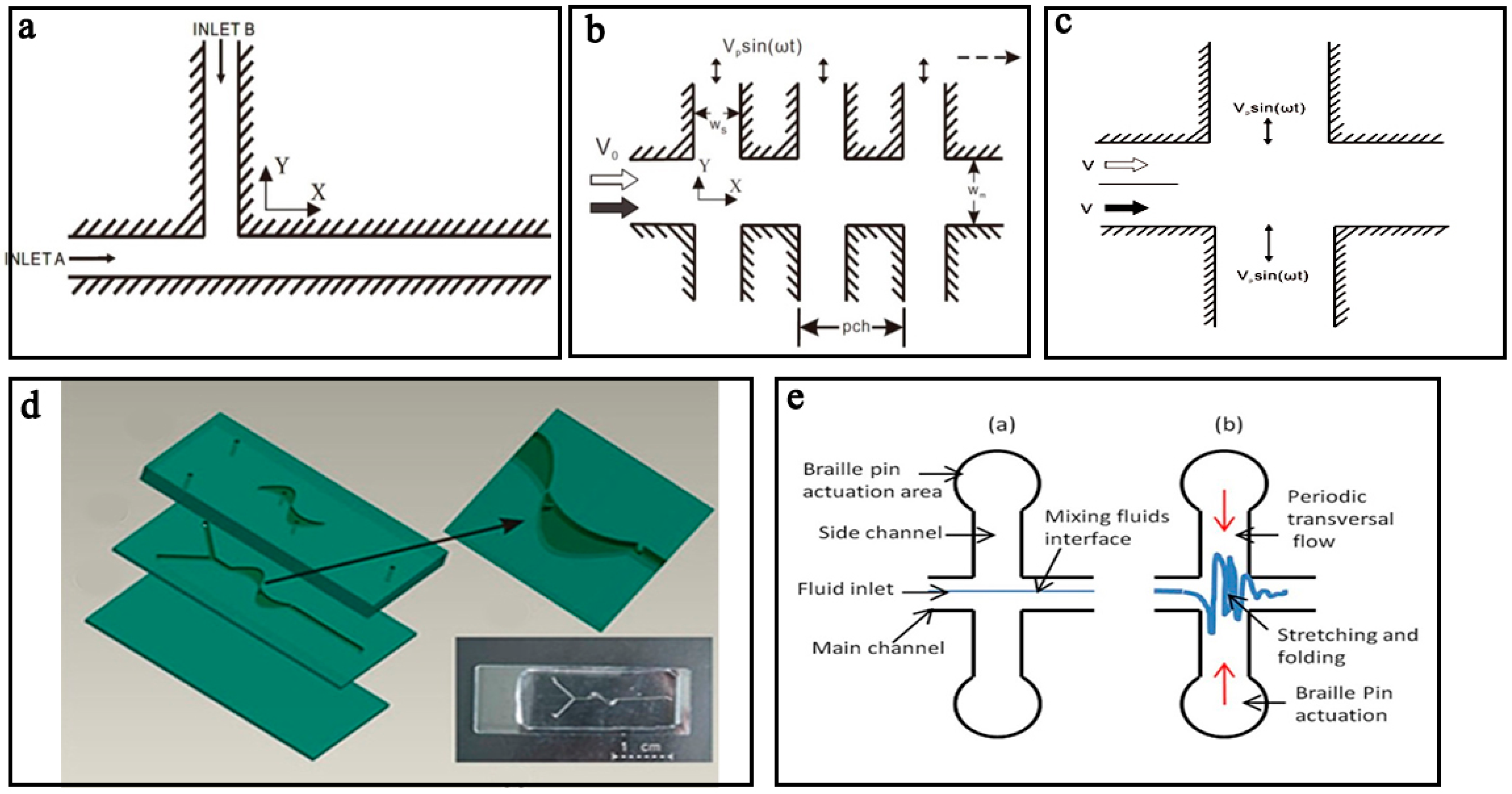
2.1. Pressure Field Driven Micromixers
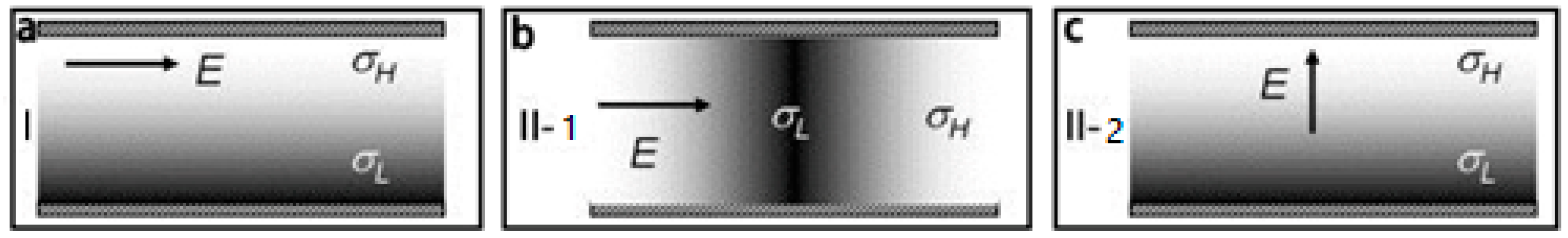
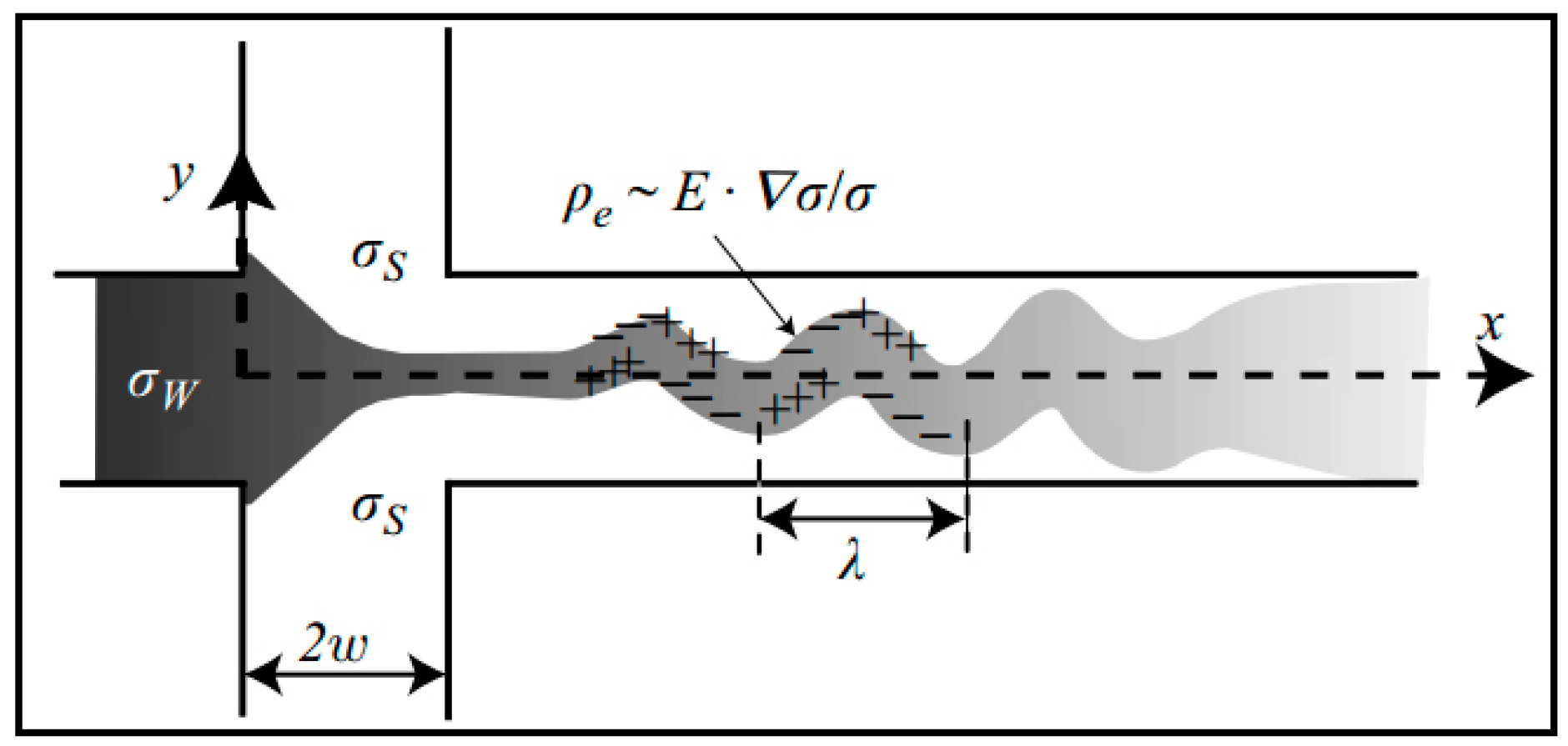
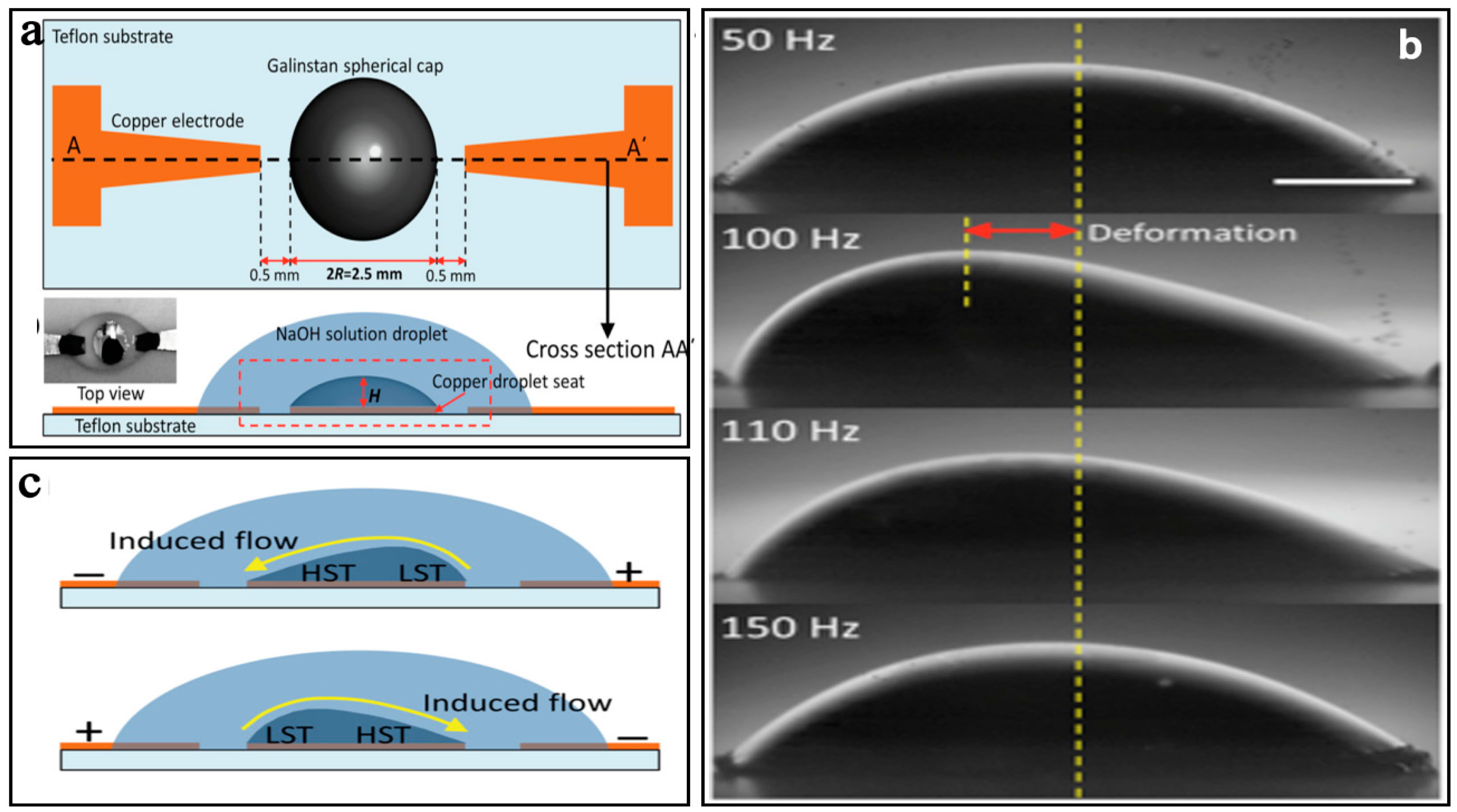
2.2. Electrical Field Driven Micromixers
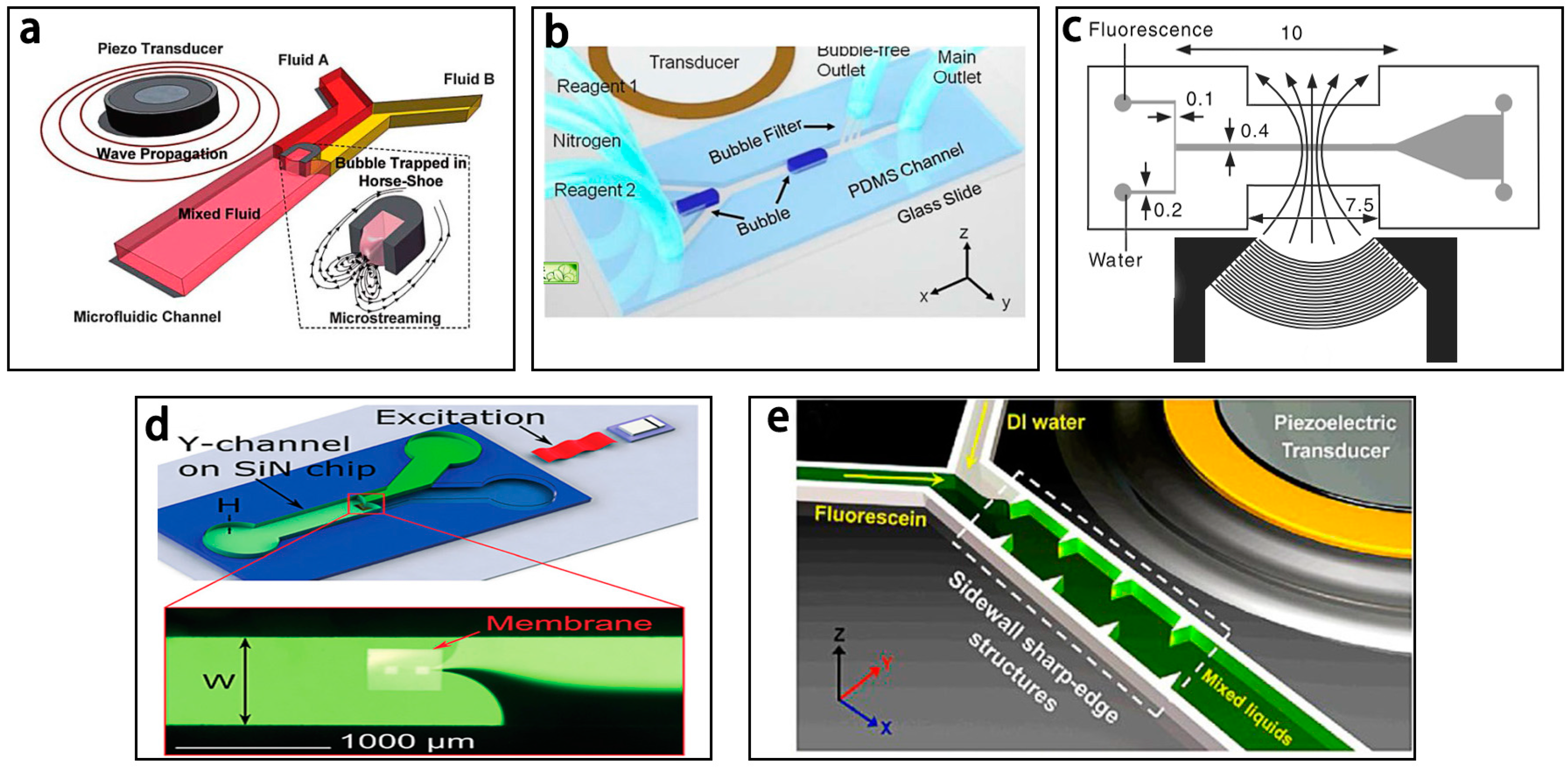
2.3. Sound Field Driven Micromixers
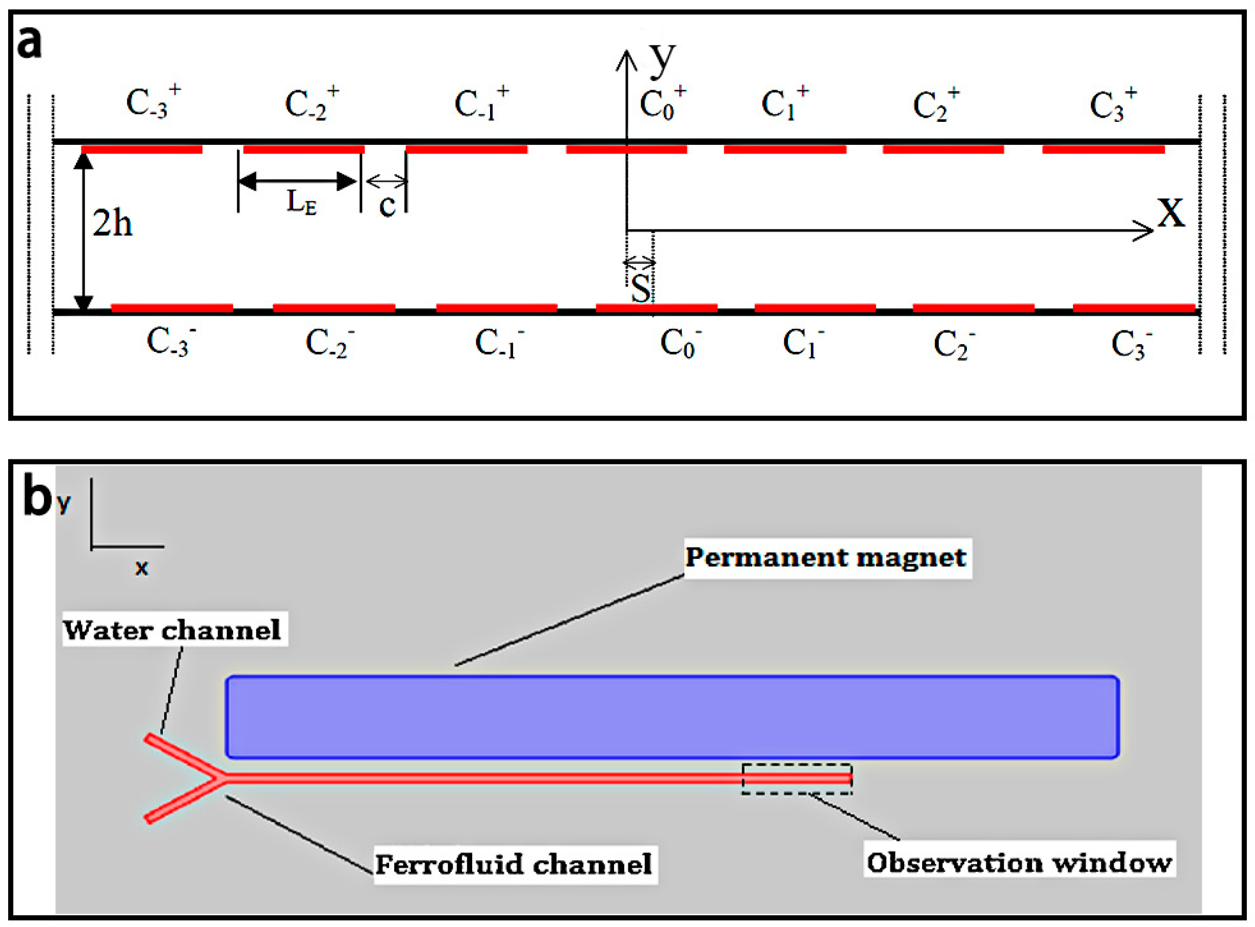
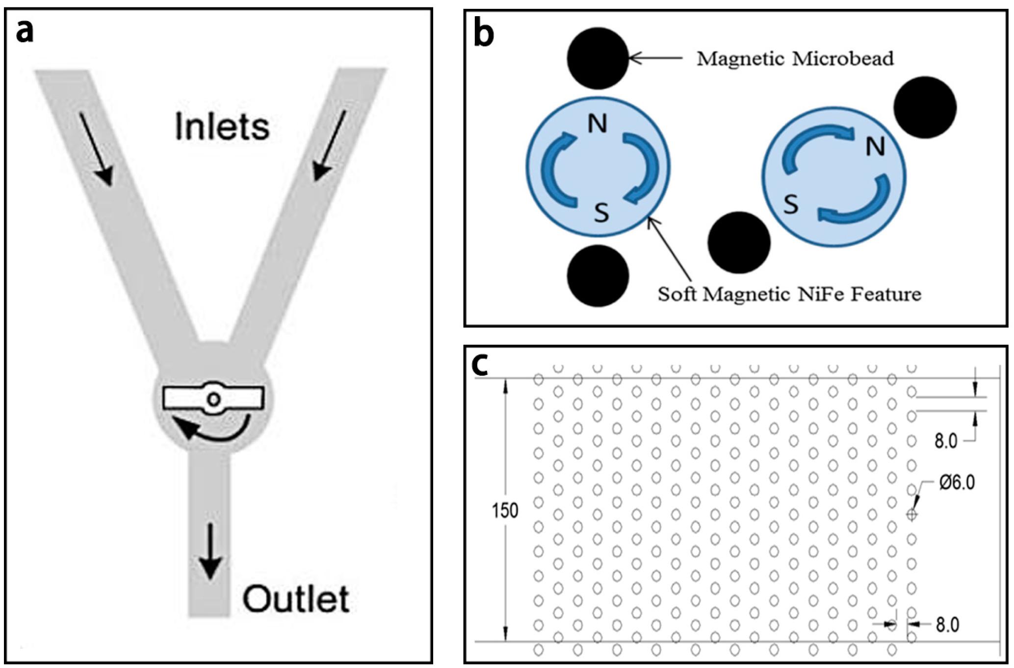
2.4. Magnetic Field Driven Micromixers
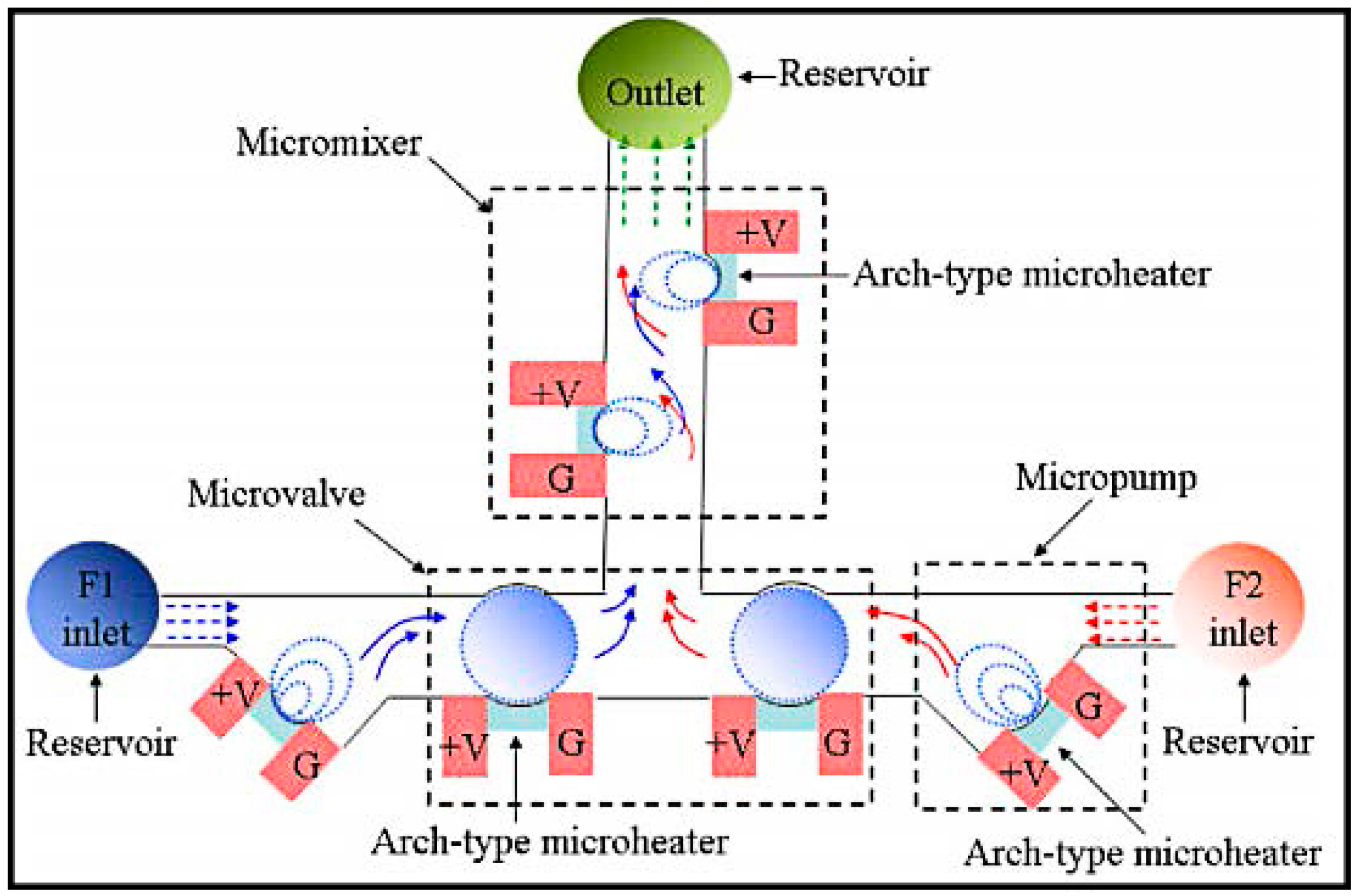
2.5. Thermal Field Driven Micromixers
2.6. Other Field Driven Micromixers
3. Passive Micromixer
3.1. 2D Passive Micromixers
3.1.1. Obstacle Based Micromixers
3.1.2. Unbalanced Collision Based Micromixers
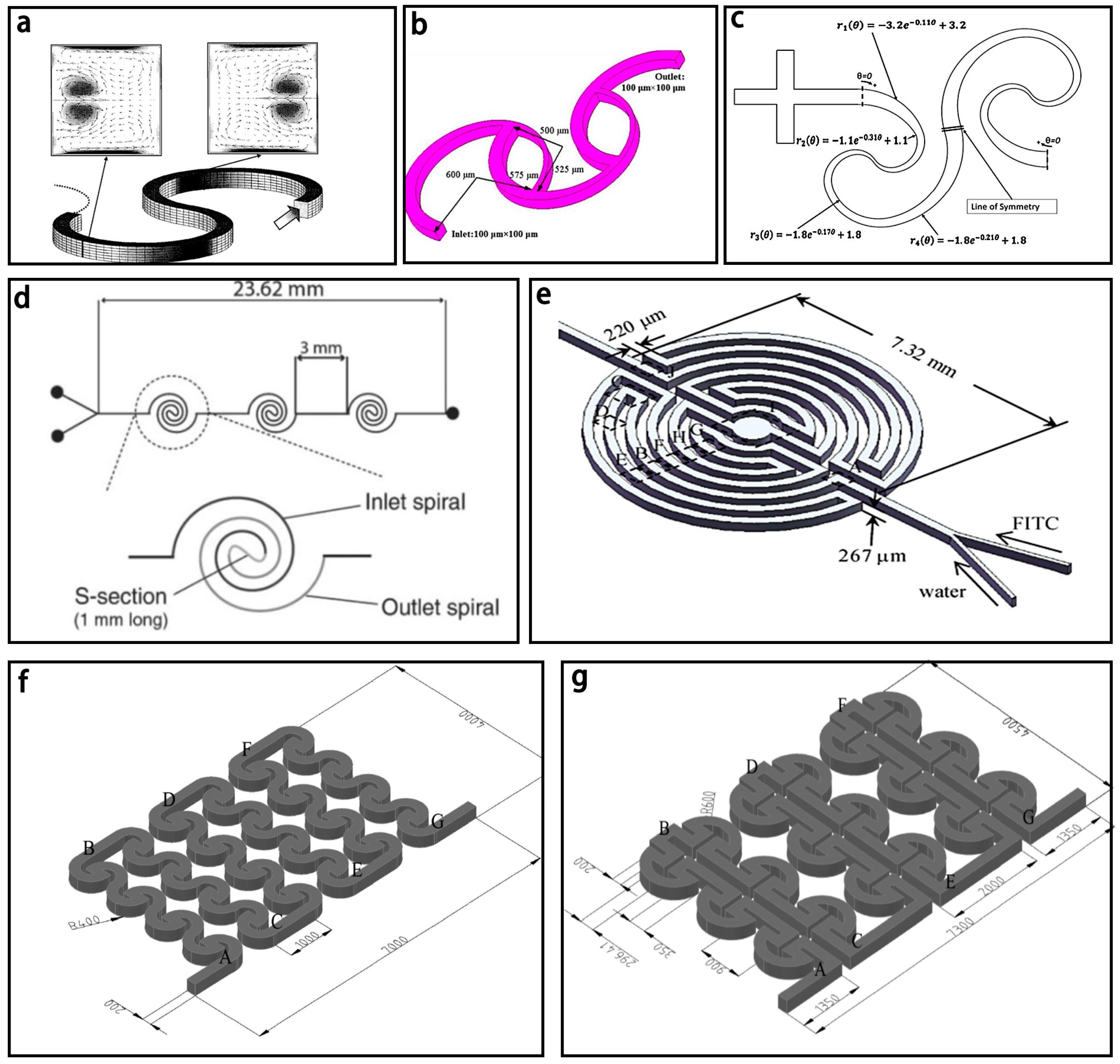
3.1.3. Spiral Based Micromixers
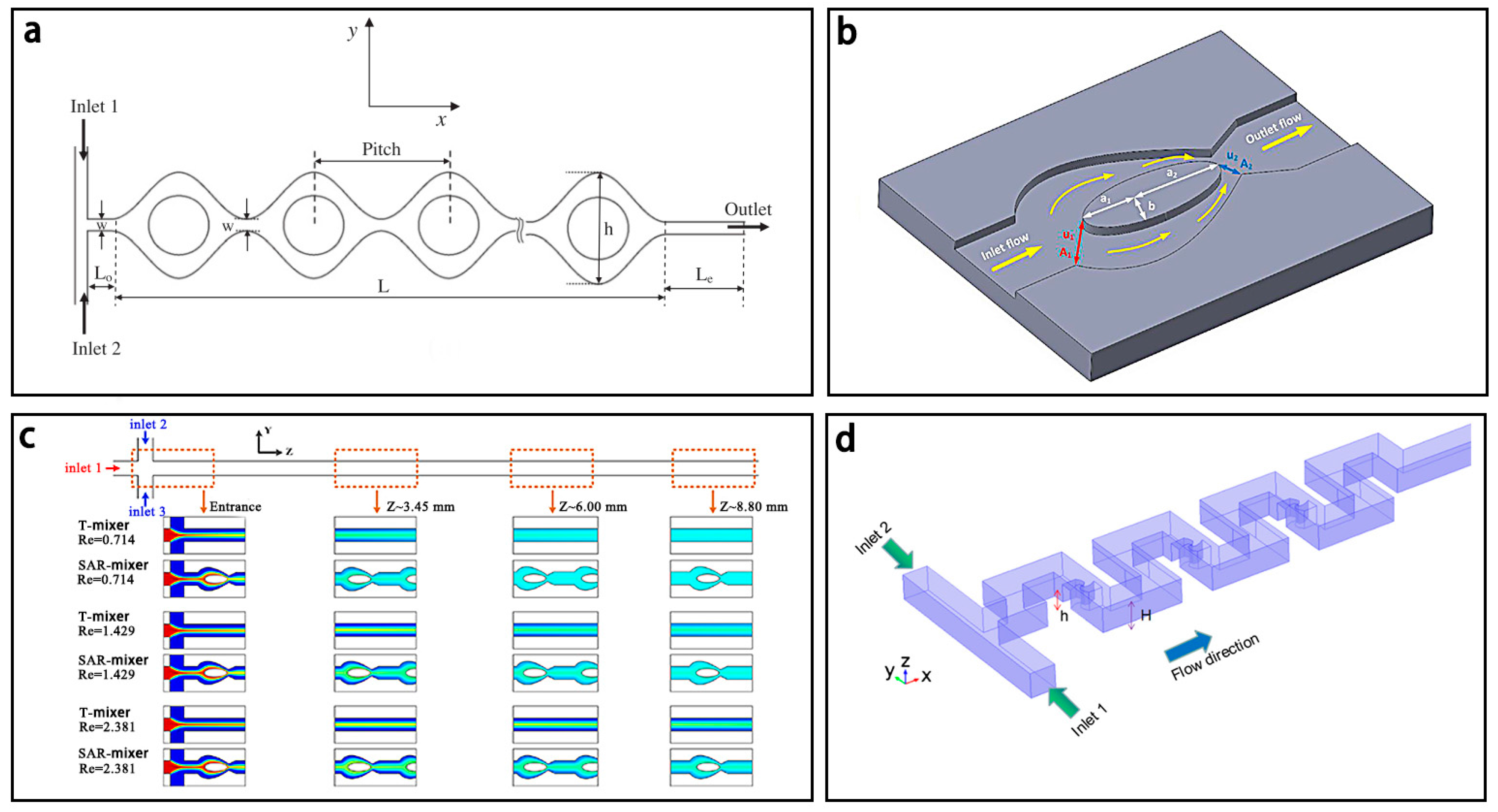
3.1.4. Convergence–Divergence Based Micromixer
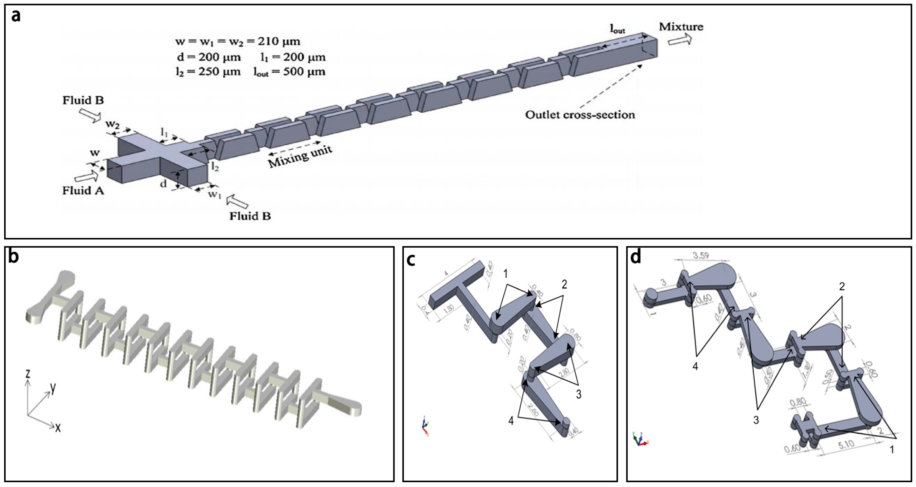
3.2. 3D Passive Micromixers
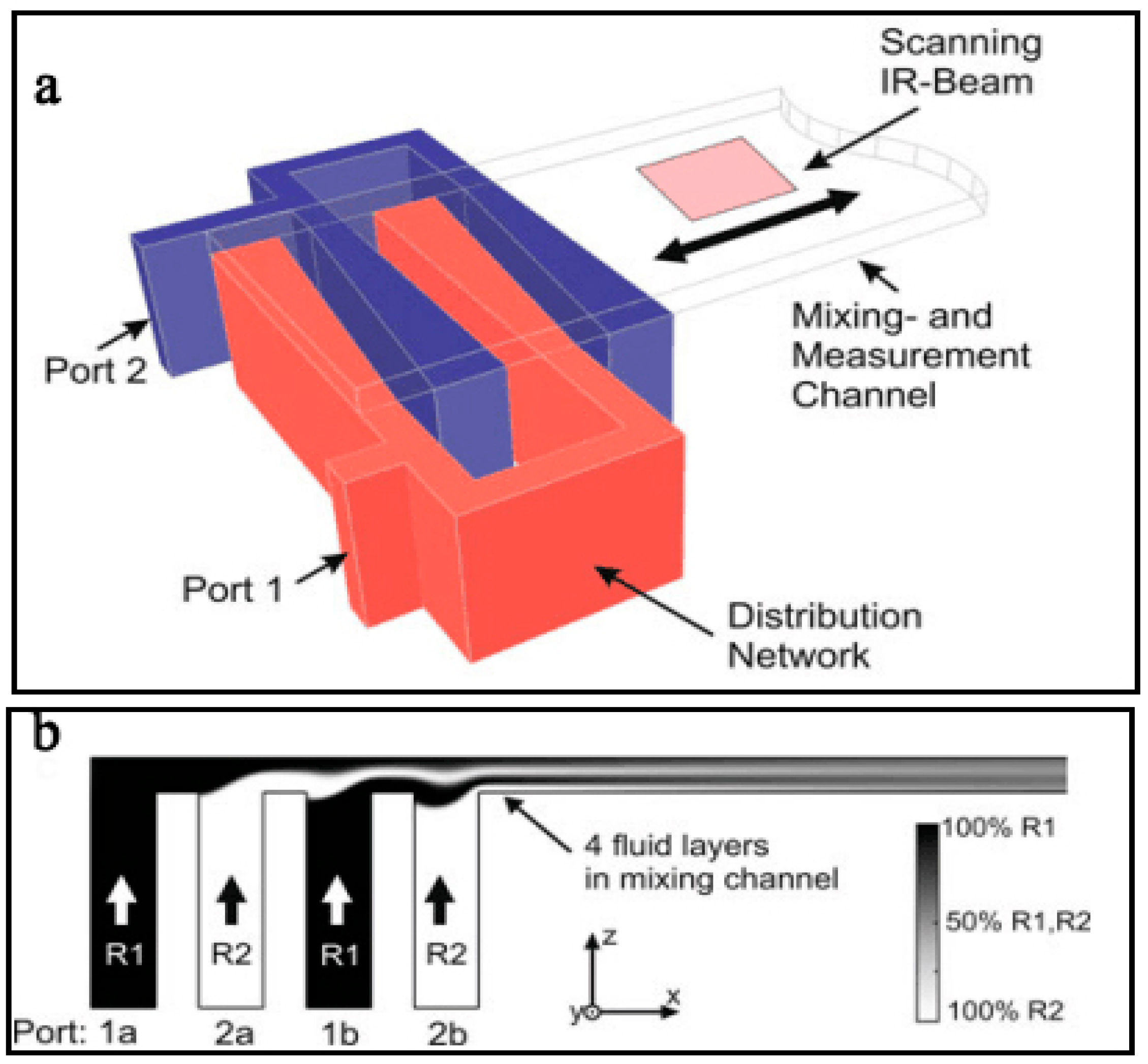
3.2.1. Lamination Based Micromixers
3.2.2. Chamber Based Micromixers
3.2.3. 3D Spiral Based Micromixers
3.2.4. Overbridge Based Micromixers
4. Conclusion and Future Trends
Acknowledgments
Author Contributions
Conflicts of Interest
References
- Whitesides, G. The lab finally comes to the chip! Lab Chip 2014, 14, 3125–3126. [Google Scholar] [CrossRef] [PubMed]
- Manz, A.; Graber, N.; Widmer, H.M. Miniaturized total chemical-analysis systems—A novel concept for chemical sensing. Sens. Actuator B-Chem. 1990, 1, 244–248. [Google Scholar] [CrossRef]
- Liu, R.H.; Stremler, M.A.; Sharp, K.V.; Olsen, M.G.; Santiago, J.G.; Adrian, R.J.; Aref, H.; Beebe, D.J. Passive mixing in a three-dimensional serpentine microchannel. J. Microelectromech. Syst. 2000, 9, 190–197. [Google Scholar] [CrossRef]
- Tekin, H.C.; Sivagnanam, V.; Ciftlik, A.T.; Sayah, A.; Vandevyver, C.; Gijs, M.A.M. Chaotic mixing using source–sink microfluidic flows in a pdms chip. Microfluid. Nanofluid. 2010, 10, 749–759. [Google Scholar] [CrossRef]
- Wang, S.; Huang, X.; Yang, C. Mixing enhancement for high viscous fluids in a microfluidic chamber. Lab Chip 2011, 11, 2081–2087. [Google Scholar] [CrossRef] [PubMed]
- Phan, H.V.; Coskun, M.B.; Sesen, M.; Pandraud, G.; Neild, A.; Alan, T. Vibrating membrane with discontinuities for rapid and efficient microfluidic mixing. Lab Chip 2015, 15, 4206–4216. [Google Scholar] [CrossRef] [PubMed]
- Du, M.; Ma, Z.; Ye, X.; Zhou, Z. On-chip fast mixing by a rotary peristaltic micropump with a single structural layer. Sci. China Technol. Sci. 2013, 56, 1047–1054. [Google Scholar] [CrossRef]
- Nguyen, N.-T.; Wu, Z. Micromixers—A review. J. Micromech. Microeng. 2005, 15, R1–R16. [Google Scholar] [CrossRef]
- Ward, K.; Fan, Z.H. Mixing in microfluidic devices and enhancement methods. J. Micromech. Microeng. 2015, 25, 094001. [Google Scholar] [CrossRef]
- Hessel, V.; Löwe, H.; Schönfeld, F. Micromixers— review on passive and active mixing principles. Chem. Eng. Sci. 2005, 60, 2479–2501. [Google Scholar] [CrossRef]
- Lee, C.Y.; Chang, C.L.; Wang, Y.N.; Fu, L.M. Microfluidic mixing: A review. Int. J. Mol. Sci. 2011, 12, 3263–3287. [Google Scholar] [CrossRef] [PubMed]
- Lee, C.Y.; Wang, W.T.; Liu, C.C.; Fu, L.M. Passive mixers in microfluidic systems: A review. Chem. Eng. J. 2016, 288, 146–160. [Google Scholar] [CrossRef]
- Wang, X.; Ma, X.; An, L.; Kong, X.; Xu, Z.; Wang, J. A pneumatic micromixer facilitating fluid mixing at a wide range flow rate for the preparation of quantum dots. Sci. China Chem. 2012, 56, 799–805. [Google Scholar] [CrossRef]
- Abbas, Y.; Miwa, J.; Zengerle, R.; von Stetten, F. Active continuous-flow micromixer using an external braille pin actuator array. Micromachines 2013, 4, 80–89. [Google Scholar] [CrossRef]
- Xia, Q.; Zhong, S. Liquid mixing enhanced by pulse width modulation in a y-shaped jet configuration. Fluid Dyn. Res. 2013, 45, 025504. [Google Scholar] [CrossRef]
- Cortes-Quiroz, C.A.; Azarbadegan, A.; Johnston, I.D.; Tracey, M.C. Analysis and design optimization of an integrated micropump-micromixer operated for bio-mems applications. In Proceedings of the 4th Micro and Nano Flows Conference, London, UK, 7–10 September 2014; pp. 261–271. [Google Scholar]
- Huang, J.J.; Lo, Y.J.; Hsieh, C.M.; Lei, U. An electro-thermal micro mixer. In Proceedings of the IEEE International Conference on Nano/micro Engineered and Molecular Systems, Kaohsiung, Taiwan, 20–23 February 2011; pp. 919–922. [Google Scholar]
- Kumar, V.; Paraschivoiu, M.; Nigam, K.D.P. Single-phase fluid flow and mixing in microchannels. Chem. Eng. Sci. 2011, 66, 1329–1373. [Google Scholar] [CrossRef]
- Posner, J.D.; Perez, C.L.; Santiago, J.G. Electric fields yield chaos in microflows. Proc. Natl. Acad. Sci. USA 2012, 109, 14353–14356. [Google Scholar] [CrossRef] [PubMed]
- Jalaal, M.; Khorshidi, B.; Esmaeilzadeh, E. Electrohydrodynamic (EHD) mixing of two miscible dielectric liquids. Chem. Eng. J. 2013, 219, 118–123. [Google Scholar] [CrossRef]
- Wang, G.R.; Yang, F.; Zhao, W. There can be turbulence in microfluidics at low reynolds number. Lab Chip 2014, 14, 1452–1458. [Google Scholar] [CrossRef] [PubMed]
- Eribol, P.; Uguz, A.K. Experimental investigation of electrohydrodynamic instabilities in micro channels. Eur. Phys. J. Spec. Top. 2015, 224, 425–434. [Google Scholar] [CrossRef]
- Thanjavur Kumar, D.; Zhou, Y.; Brown, V.; Lu, X.; Kale, A.; Yu, L.; Xuan, X. Electric field-induced instabilities in ferrofluid microflows. Microfluid. Nanofluid. 2015, 19, 43–52. [Google Scholar] [CrossRef]
- Lang, Q.; Ren, Y.; Hobson, D.; Tao, Y.; Hou, L.; Jia, Y.; Hu, Q.; Liu, J.; Zhao, X.; Jiang, H. In-plane microvortices micromixer-based AC electrothermal for testing drug induced death of tumor cells. Biomicrofluidics 2016, 10, 064102. [Google Scholar] [CrossRef] [PubMed]
- Wu, Y.; Ren, Y.; Tao, Y.; Hou, L.; Hu, Q.; Jiang, H. A novel micromixer based on the alternating current-flow field effect transistor. Lab Chip 2016, 17, 186–197. [Google Scholar] [CrossRef] [PubMed]
- Zhou, T.; Wang, H.; Shi, L.; Liu, Z.; Joo, S. An enhanced electroosmotic micromixer with an efficient asymmetric lateral structure. Micromachines 2016, 7, 218. [Google Scholar] [CrossRef]
- Baygents, J.C.; Baldessari, F. Electrohydrodynamic instability in a thin fluid layer with an electrical conductivity gradient. Phys. Fluids 1998, 10, 301–311. [Google Scholar] [CrossRef]
- Oddy, M.H.; Santiago, J.G.; Mikkelsen, J.C. Electrokinetic instability micromixing. Anal. Chem. 2001, 73, 5822–5832. [Google Scholar] [CrossRef] [PubMed]
- Chen, C.-H.; Lin, H.A.O.; Lele, S.K.; Santiago, J.G. Convective and absolute electrokinetic instability with conductivity gradients. J. Fluid Mech. 2005, 524, 263–303. [Google Scholar] [CrossRef]
- Posner, J.D.; Santiago, J.G. Convective instability of electrokinetic flows in a cross-shaped microchannel. J. Fluid Mech. 2006, 555, 1. [Google Scholar] [CrossRef]
- Boy, D.A.; Storey, B.D. Electrohydrodynamic instabilities in microchannels with time periodic forcing. Phys. Rev. E 2007, 76, 026304. [Google Scholar] [CrossRef] [PubMed]
- Chang, C.-C.; Yang, R.-J. Electrokinetic mixing in microfluidic systems. Microfluid. Nanofluid. 2007, 3, 501–525. [Google Scholar] [CrossRef]
- Mansur, E.A.; Mingxing, Y.E.; Yundong, W.A.N.G.; Youyuan, D.A.I. A state-of-the-art review of mixing in microfluidic mixers. Chin. J. Chem. Eng. 2008, 16, 503–516. [Google Scholar] [CrossRef]
- Xie, Y.; Ahmed, D.; Lapsley, M.I.; Lin, S.C.; Nawaz, A.A.; Wang, L.; Huang, T.J. Single-shot characterization of enzymatic reaction constants km and kcat by an acoustic-driven, bubble-based fast micromixer. Anal. Chem. 2012, 84, 7495–7501. [Google Scholar] [CrossRef] [PubMed]
- Xu, L.; Lee, H.; Panchapakesan, R.; Oh, K.W. Fusion and sorting of two parallel trains of droplets using a railroad-like channel network and guiding tracks. Lab Chip 2012, 12, 3936–3942. [Google Scholar] [CrossRef] [PubMed]
- Huang, P.H.; Xie, Y.; Ahmed, D.; Rufo, J.; Nama, N.; Chen, Y.; Chan, C.Y.; Huang, T.J. An acoustofluidic micromixer based on oscillating sidewall sharp-edges. Lab Chip 2013, 13, 3847–3852. [Google Scholar] [CrossRef] [PubMed]
- Wang, C.; Rallabandi, B.; Hilgenfeldt, S. Frequency dependence and frequency control of microbubble streaming flows. Phys. Fluids 2013, 25, 022002. [Google Scholar] [CrossRef]
- Ozcelik, A.; Ahmed, D.; Xie, Y.; Nama, N.; Qu, Z.; Nawaz, A.A.; Huang, T.J. An acoustofluidic micromixer via bubble inception and cavitation from microchannel sidewalls. Anal. Chem. 2014, 86, 5083–5088. [Google Scholar] [CrossRef] [PubMed]
- Brandhoff, L.; Zirath, H.; Salas, M.; Haller, A.; Peham, J.; Wiesinger-Mayr, H.; Spittler, A.; Schnetz, G.; Lang, W.; Vellekoop, M.J. A multi-purpose ultrasonic streaming mixer for integrated magnetic bead elisas. J. Micromech. Microeng. 2015, 25, 104001. [Google Scholar] [CrossRef]
- Van ‘t Oever, J.; Spannenburg, N.; Offerhaus, H.; van den Ende, D.; Herek, J.; Mugele, F. In-chip direct laser writing of a centimeter-scale acoustic micromixer. J. Micro/Nanolithogr. MEMS MOEMS 2015, 14, 023503. [Google Scholar] [CrossRef]
- Ang, K.M.; Yeo, L.Y.; Hung, Y.M.; Tan, M.K. Amplitude modulation schemes for enhancing acoustically-driven microcentrifugation and micromixing. Biomicrofluidics 2016, 10, 054106. [Google Scholar] [CrossRef] [PubMed]
- Nama, N.; Huang, P.H.; Huang, T.J.; Costanzo, F. Investigation of micromixing by acoustically oscillated sharp-edges. Biomicrofluidics 2016, 10, 024124. [Google Scholar] [CrossRef] [PubMed]
- Orbay, S.; Ozcelik, A.; Lata, J.; Kaynak, M.; Wu, M.; Huang, T.J. Mixing high-viscosity fluids via acoustically driven bubbles. J. Micromech. Microeng. 2017, 27, 015008. [Google Scholar] [CrossRef]
- Eickenberg, B.; Wittbracht, F.; Stohmann, P.; Schubert, J.R.; Brill, C.; Weddemann, A.; Hütten, A. Continuous-flow particle guiding based on dipolar coupled magnetic superstructures in rotating magnetic fields. Lab Chip 2013, 13, 920. [Google Scholar] [CrossRef] [PubMed]
- Gray, B.L.; Becker, H.; Owen, D.; Ballard, M.; Mao, W.; Alexeev, A.; Hesketh, P.J. Magnetic microbeads for sampling and mixing in a microchannel. Int. Soc. Opt. Photonics 2014, 8976, 89760C. [Google Scholar] [CrossRef]
- Köhler, J.; Ghadiri, R.; Ksouri, S.I.; Guo, Q.; Gurevich, E.L.; Ostendorf, A. Generation of microfluidic flow using an optically assembled and magnetically driven microrotor. J. Phys. D: Appl. Phys. 2014, 47, 505501. [Google Scholar] [CrossRef]
- La, M.; Kim, W.; Yang, W.; Kim, H.W.; Kim, D.S. Design and numerical simulation of complex flow generation in a microchannel by magnetohydrodynamic (mhd) actuation. Int. J. Precis. Eng. Manuf. 2014, 15, 463–470. [Google Scholar] [CrossRef]
- Cao, Q.; Han, X.; Li, L. An active microfluidic mixer utilizing a hybrid gradient magnetic field. Int. J. Appl. Electromagn. Mech. 2015, 47, 583–592. [Google Scholar]
- Kitenbergs, G.; Erglis, K.; Perzynski, R.; Cēbers, A. Magnetic particle mixing with magnetic micro-convection for microfluidics. J. Magn. Magn. Mater. 2015, 380, 227–230. [Google Scholar] [CrossRef]
- Veldurthi, N.; Chandel, S.; Bhave, T.; Bodas, D. Computational fluid dynamic analysis of poly(dimethyl siloxane) magnetic actuator based micromixer. Sens. Actuators B Chem. 2015, 212, 419–424. [Google Scholar] [CrossRef]
- Ballard, M.; Owen, D.; Mills, Z.G.; Hesketh, P.J.; Alexeev, A. Orbiting magnetic microbeads enable rapid microfluidic mixing. Microfluid. Nanofluid. 2016, 20, 88. [Google Scholar] [CrossRef]
- Chang, M.; Gabayno, J.L.F.; Ye, R.; Huang, K.-W.; Chang, Y.-J. Mixing efficiency enhancing in micromixer by controlled magnetic stirring of fe3o4 nanomaterial. Microsyst. Technol. 2016, 23, 457–463. [Google Scholar] [CrossRef]
- Hejazian, M.; Phan, D.-T.; Nguyen, N.-T. Mass transport improvement in microscale using diluted ferrofluid and a non-uniform magnetic field. RSC Adv. 2016, 6, 62439–62444. [Google Scholar] [CrossRef]
- Owen, D.; Ballard, M.; Alexeev, A.; Hesketh, P.J. Rapid microfluidic mixing via rotating magnetic microbeads. Sens. Actuators A: Phys. 2016, 251, 84–91. [Google Scholar] [CrossRef]
- Veldurthi, N.; Ghoderao, P.; Sahare, S.; Kumar, V.; Bodas, D.; Kulkarni, A.; Bhave, T. Magnetically active micromixer assisted synthesis of drug nanocomplexes exhibiting strong bactericidal potential. Mater. Sci. Eng. C 2016, 68, 455–464. [Google Scholar] [CrossRef] [PubMed]
- Hejazian, M.; Nguyen, N.-T. A rapid magnetofluidic micromixer using diluted ferrofluid. Micromachines 2017, 8, 37. [Google Scholar] [CrossRef]
- Nouri, D.; Zabihi-Hesari, A.; Passandideh-Fard, M. Rapid mixing in micromixers using magnetic field. Sens. Actuators A: Phys. 2017, 255, 79–86. [Google Scholar] [CrossRef]
- Dong, X.X.; Zhang, L.; Fu, J. Laser-induced thermal bubble-mixing on a microfluidic platform for lab-on-a-chip applications. Adv. Mater. Res. 2012, 557–559, 2197–2201. [Google Scholar] [CrossRef]
- Huang, K.-R.; Chang, J.-S.; Chao, S.D.; Wung, T.-S.; Wu, K.-C. Study of active micromixer driven by electrothermal force. Jpn. J. Appl. Phys. 2012, 51, 047002. [Google Scholar] [CrossRef]
- Sasaki, N.; Kitamori, T.; Kim, H.B. Fluid mixing using ac electrothermal flow on meandering electrodes in a microchannel. Electrophoresis 2012, 33, 2668–2673. [Google Scholar] [CrossRef] [PubMed]
- Huang, C.; Tsou, C. The implementation of a thermal bubble actuated microfluidic chip with microvalve, micropump and micromixer. Sens. Actuators A: Phys. 2014, 210, 147–156. [Google Scholar] [CrossRef]
- Zhang, F.; Chen, H.; Chen, B.; Wu, J. Alternating current electrothermal micromixer with thin film resistive heaters. Adv. Mech. Eng. 2016, 8, 168781401664626. [Google Scholar] [CrossRef]
- Kunti, G.; Bhattacharya, A.; Chakraborty, S. Rapid mixing with high-throughput in a semi-active semi-passive micromixer. Electrophoresis 2017, 38, 1310–1317. [Google Scholar] [CrossRef] [PubMed]
- Glasgow, I.; Aubry, N. Enhancement of microfluidic mixing using time pulsing. Lab Chip 2003, 3, 114–120. [Google Scholar] [CrossRef] [PubMed]
- Niu, X.Z.; Lee, Y.K. Efficient spatial-temporal chaotic mixing in microchannels. J. Micromech. Microeng. 2003, 13, 454–462. [Google Scholar] [CrossRef]
- Tabeling, P.; Chabert, M.; Dodge, A.; Jullien, C.; Okkels, F. Chaotic mixing in cross-channel micromixers. Philos. T. R. Soc. A 2004, 362, 987–1000. [Google Scholar] [CrossRef] [PubMed]
- Deshmukh, A.A.; Liepmann, D.; Pisano, A.P. Continuous micromixer with pulsatile micropumps. In Proceedings of the Technical Digest of the IEEE Solid State Sensor and Actuator Workshop, Hilton Head Island, SC, USA, January 2000; pp. 73–76. [Google Scholar]
- Xia, Q.; Zhong, S. Quantification of liquid mixing enhanced by alternatively pulsed injection in a confined jet configuration. J. Vis. 2011, 15, 57–66. [Google Scholar] [CrossRef]
- Khoshmanesh, K.; Almansouri, A.; Albloushi, H.; Yi, P.; Soffe, R.; Kalantar-zadeh, K. A multi-functional bubble-based microfluidic system. Sci. Rep. 2015, 5, 9942. [Google Scholar] [CrossRef] [PubMed]
- Sun, C.-L.; Sie, J.-Y. Active mixing in diverging microchannels. Microfluid. Nanofluid. 2009, 8, 485–495. [Google Scholar] [CrossRef]
- Yi-Kuen, L.; Deval, J.; Tabeling, P.; Chih-Ming, H. Chaotic mixing in electrokinetically and pressure driven micro flows. In Proceedings of the 14th IEEE International Conference on Micro Electro Mechanical Systems, Interlaken, Switzerland, 25 January 2001; pp. 483–486. [Google Scholar] [CrossRef]
- Lin, H. Electrokinetic instability in microchannel flows: A review. Mech. Res. Commun. 2009, 36, 33–38. [Google Scholar] [CrossRef]
- Tang, S.-Y.; Sivan, V.; Petersen, P.; Zhang, W.; Morrison, P.D.; Kalantar-zadeh, K.; Mitchell, A.; Khoshmanesh, K. Liquid metal actuator for inducing chaotic advection. Adv. Funct. Mater. 2014, 24, 5851–5858. [Google Scholar] [CrossRef]
- Tang, S.Y.; Khoshmanesh, K.; Sivan, V.; Petersen, P.; O’Mullane, A.P.; Abbott, D.; Mitchell, A.; Kalantar-zadeh, K. Liquid metal enabled pump. Proc. Natl. Acad. Sci. USA 2014, 111, 3304–3309. [Google Scholar] [CrossRef] [PubMed]
- Moroney, R.M.; White, R.M.; Howe, R.T. Ultrasonically induced microtransport. In Proceedings of the IEEE Micro Electro Mechanical Systems, Nara, Japan, 1–2 January 1991; pp. 277–282. [Google Scholar]
- Hashmi, A.; Yu, G.; Reilly-Collette, M.; Heiman, G.; Xu, J. Oscillating bubbles: A versatile tool for lab on a chip applications. Lab Chip 2012, 12, 4216–4227. [Google Scholar] [CrossRef] [PubMed]
- Liu, R.H.; Yang, J.; Pindera, M.Z.; Athavale, M.; Grodzinski, P. Bubble-induced acoustic micromixing. Lab Chip 2002, 2, 151–157. [Google Scholar] [CrossRef] [PubMed]
- Liu, R.H.; Lenigk, R.; Druyor-Sanchez, R.L.; Yang, J.N.; Grodzinski, P. Hybridization enhancement using cavitation microstreaming. Anal. Chem. 2003, 75, 1911–1917. [Google Scholar] [CrossRef] [PubMed]
- Ahmed, D.; Mao, X.; Shi, J.; Juluri, B.K.; Huang, T.J. A millisecond micromixer via single-bubble-based acoustic streaming. Lab Chip 2009, 9, 2738–2741. [Google Scholar] [CrossRef] [PubMed]
- Wang, S.; Huang, X.; Yang, C. Microfluidic bubble generation by acoustic field for mixing enhancement. J. Heat Transf. 2012, 134, 051014. [Google Scholar] [CrossRef]
- Meng, L.; Cai, F.; Jin, Q.; Niu, L.; Jiang, C.; Wang, Z.; Wu, J.; Zheng, H. Acoustic aligning and trapping of microbubbles in an enclosed pdms microfluidic device. Sens. Actuators B Chem. 2011, 160, 1599–1605. [Google Scholar] [CrossRef]
- Luong, T.D.; Phan, V.N.; Nguyen, N.T. High-throughput micromixers based on acoustic streaming induced by surface acoustic wave. Microfluid. Nanofluid. 2011, 10, 619–625. [Google Scholar] [CrossRef]
- Qian, S.; Bau, H.H. Magneto-hydrodynamic stirrer for stationary and moving fluids. Sens. Actuat B-Chem. 2005, 106, 859–870. [Google Scholar] [CrossRef]
- Ryu, K.S.; Shaikh, K.; Goluch, E.; Fan, Z.; Liu, C. Micro magnetic stir-bar mixer integrated with parylene microfluidic channels. Lab Chip 2004, 4, 608–613. [Google Scholar] [CrossRef] [PubMed]
- Chen, C.Y.; Chen, C.Y.; Lin, C.Y.; Hu, Y.T. Magnetically actuated artificial cilia for optimum mixing performance in microfluidics. Lab Chip 2013, 13, 2834–2839. [Google Scholar] [CrossRef] [PubMed]
- Tsou, C.; Huang, C. Thermal bubble microfluidic gate based on SOI wafer. J. Microelectromech. Syst. 2009, 18, 852–859. [Google Scholar] [CrossRef]
- La, M.; Park, S.J.; Kim, H.W.; Park, J.J.; Ahn, K.T.; Ryew, S.M.; Kim, D.S. A centrifugal force-based serpentine micromixer (CSM) on a plastic lab-on-a-disk for biochemical assays. Microfluid. Nanofluid. 2012, 15, 87–98. [Google Scholar] [CrossRef]
- Aguirre, G.R.; Efremov, V.; Kitsara, M.; Ducrée, J. Integrated micromixer for incubation and separation of cancer cells on a centrifugal platform using inertial and dean forces. Microfluid. Nanofluid. 2014, 18, 513–526. [Google Scholar] [CrossRef]
- Shamloo, A.; Madadelahi, M.; Akbari, A. Numerical simulation of centrifugal serpentine micromixers and analyzing mixing quality parameters. Chem. Eng. Process.: Process Intensif. 2016, 104, 243–252. [Google Scholar] [CrossRef]
- Haeberle, S.; Brenner, T.; Schlosser, H.P.; Zengerle, R.; Ducrée, J. Centrifugal micromixer. Chem. Eng. Technol. 2005, 28, 613–616. [Google Scholar] [CrossRef]
- Leung, W.W.-F.; Ren, Y. Crossflow and mixing in obstructed and width-constricted rotating radial microchannel. Int. J. Heat Mass Transf. 2013, 64, 457–467. [Google Scholar] [CrossRef]
- Ansari, M.A.; Kim, K.-Y. Mixing performance of unbalanced split and recombine micomixers with circular and rhombic sub-channels. Chem. Eng. J. 2010, 162, 760–767. [Google Scholar] [CrossRef]
- Kamholz, A.E.; Weigl, B.H.; Finlayson, B.A.; Yager, P. Quantitative analysis of molecular interaction in a microfluidic channel: The t-sensor. Anal. Chem. 1999, 71, 5340. [Google Scholar] [CrossRef] [PubMed]
- Mengeaud, V.; Josserand, J.; Girault, H.H. Mixing processes in a zigzag microchannel: Finite element simulations and optical study. Anal. Chem. 2002, 74, 4279–4286. [Google Scholar] [CrossRef] [PubMed]
- Hossain, S.; Kim, K.-Y. Mixing analysis of passive micromixer with unbalanced three-split rhombic sub-channels. Micromachines 2014, 5, 913–928. [Google Scholar] [CrossRef]
- Li, J.; Xia, G.; Li, Y. Numerical and experimental analyses of planar asymmetric split-and-recombine micromixer with dislocation sub-channels. J. Chem. Technol. Biotechnol. 2013, 88, 1757–1765. [Google Scholar] [CrossRef]
- Wang, L.; Ma, S.; Wang, X.; Bi, H.; Han, X. Mixing enhancement of a passive microfluidic mixer containing triangle baffles. Asia-Pac. J. Chem. Eng. 2014, 9, 877–885. [Google Scholar] [CrossRef]
- Alam, A.; Afzal, A.; Kim, K.-Y. Mixing performance of a planar micromixer with circular obstructions in a curved microchannel. Chem. Eng. Res. Des. 2014, 92, 423–434. [Google Scholar] [CrossRef]
- Scherr, T.; Quitadamo, C.; Tesvich, P.; Park, D.S.; Tiersch, T.; Hayes, D.; Choi, J.W.; Nandakumar, K.; Monroe, W.T. A planar microfluidic mixer based on logarithmic spirals. J. Micromech. Microeng. 2012, 22, 55019. [Google Scholar] [CrossRef] [PubMed]
- He, X.; Wei, D.; Deng, Z.; Yang, S.; Cai, S. Mixing performance of a novel passive micromixer with logarithmic spiral channel. Paiguan Jixie Gongcheng Xuebao/J. Drain. Irrig. Mach. Eng. 2014, 32, 968–972. [Google Scholar]
- Afzal, A.; Kim, K.-Y. Multi-objective optimization of a passive micromixer based on periodic variation of velocity profile. Chem. Eng. Commun. 2014, 202, 322–331. [Google Scholar] [CrossRef]
- Wu, C.-Y.; Tsai, R.-T. Fluid mixing via multidirectional vortices in converging–diverging meandering microchannels with semi-elliptical side walls. Chem. Eng. J. 2013, 217, 320–328. [Google Scholar] [CrossRef]
- Afzal, A.; Kim, K.-Y. Passive split and recombination micromixer with convergent–divergent walls. Chem. Eng. J. 2012, 203, 182–192. [Google Scholar] [CrossRef]
- Tran-Minh, N.; Dong, T.; Karlsen, F. An efficient passive planar micromixer with ellipse-like micropillars for continuous mixing of human blood. Comput. Methods Programs Biomed. 2014, 117, 20–29. [Google Scholar] [CrossRef] [PubMed]
- Chen, X.; Li, T. A novel design for passive misscromixers based on topology optimization method. Biomed. Microdevices 2016, 18, 57. [Google Scholar] [CrossRef] [PubMed]
- Chen, X.; Li, T. A novel passive micromixer designed by applying an optimization algorithm to the zigzag microchannel. Chem. Eng. J. 2017, 313, 1406–1414. [Google Scholar] [CrossRef]
- The, H.L.; Le-Thanh, H.; Tran-Minh, N.; Karlsen, F. A novel passive micromixer with trapezoidal blades for high mixing efficiency at low reynolds number flow. In Proceedings of the 2014 Middle East Conference on Biomedical Engineering (MECBME), Doha, Qatar, 17–20 February 2014; pp. 25–28. [Google Scholar]
- The, H.L.; Ta, B.Q.; Thanh, H.L.; Dong, T.; Thoi, T.N.; Karlsen, F. Geometric effects on mixing performance in a novel passive micromixer with trapezoidal-zigzag channels. J. Micromech. Microeng. 2015, 25, 094004. [Google Scholar] [CrossRef]
- Le The, H.; Tran-Minh, N.; Le-Thanh, H.; Karlsen, F. A novel micromixer with multimixing mechanisms for high mixing efficiency at low reynolds number. In Proceedings of the 2014 9th Ieee International Conference on Nano/Micro Engineered and Molecular Systems (NEMS), Waikiki Beach, HI, USA, 13–16 April 2014; pp. 653–656. [Google Scholar]
- Alam, A.; Kim, K.-Y. Mixing performance of a planar micromixer with circular chambers and crossing constriction channels. Sens. Actuators B Chem. 2013, 176, 639–652. [Google Scholar] [CrossRef]
- Viktorov, V.; Mahmud, M.R.; Visconte, C. Numerical study of fluid mixing at different inlet flow-rate ratios in tear-drop and chain micromixers compared to a new h-c passive micromixer. Eng. Appl. Comput. Fluid Mech. 2016, 10, 182–192. [Google Scholar] [CrossRef]
- Yang, J.; Qi, L.; Chen, Y.; Ma, H. Design and fabrication of a three dimensional spiral micromixer. Chin. J. Chem. 2013, 31, 209–214. [Google Scholar] [CrossRef]
- Liu, K.; Yang, Q.; Chen, F.; Zhao, Y.; Meng, X.; Shan, C.; Li, Y. Design and analysis of the cross-linked dual helical micromixer for rapid mixing at low reynolds numbers. Microfluid. Nanofluid. 2015, 19, 169–180. [Google Scholar] [CrossRef]
- Sheu, T.S.; Chen, S.J.; Chen, J.J. Mixing of a split and recombine micromixer with tapered curved microchannels. Chem. Eng. Sci. 2012, 71, 321–332. [Google Scholar] [CrossRef]
- Li, X.; Chang, H.; Liu, X.; Ye, F.; Yuan, W. A 3-d overbridge-shaped micromixer for fast mixing over a wide range of reynolds numbers. J. Microelectromech. Syst. 2015, 24, 1391–1399. [Google Scholar] [CrossRef]
- Yang, A.-S.; Chuang, F.-C.; Chen, C.-K.; Lee, M.-H.; Chen, S.-W.; Su, T.-L.; Yang, Y.-C. A high-performance micromixer using three-dimensional tesla structures for bio-applications. Chem. Eng. J. 2015, 263, 444–451. [Google Scholar] [CrossRef]
- Feng, X.; Ren, Y.; Jiang, H. An effective splitting-and-recombination micromixer with self-rotated contact surface for wide reynolds number range applications. Biomicrofluidics 2013, 7, 54121. [Google Scholar] [CrossRef] [PubMed]
- Hossain, S.; Lee, I.; Kim, S.M.; Kim, K.-Y. A micromixer with two-layer serpentine crossing channels having excellent mixing performance at low reynolds numbers. Chem. Eng. J. 2017, 327, 268–277. [Google Scholar] [CrossRef]
- Stroock, A.D.; Dertinger, S.K.; Ajdari, A.; Mezic, I.; Stone, H.A.; Whitesides, G.M. Chaotic mixer for microchannels. Science 2002, 295, 647–651. [Google Scholar] [CrossRef] [PubMed]
- Howell, P.B., Jr.; Mott, D.R.; Fertig, S.; Kaplan, C.R.; Golden, J.P.; Oran, E.S.; Ligler, F.S. A microfluidic mixer with grooves placed on the top and bottom of the channel. Lab Chip 2005, 5, 524–530. [Google Scholar] [CrossRef] [PubMed]
- Hossain, S.; Husain, A.; Kim, K.-Y. Optimization of micromixer with staggered herringbone grooves on top and bottom walls. Eng. Appl. Comput. Fluid Mech. 2014, 5, 506–516. [Google Scholar] [CrossRef]
- Bhagat, A.A.S.; Peterson, E.T.K.; Papautsky, I. A passive planar micromixer with obstructions for mixing at low reynolds numbers. J. Micromech. Microeng. 2007, 17, 1017–1024. [Google Scholar] [CrossRef]
- Sadegh Cheri, M.; Latifi, H.; Salehi Moghaddam, M.; Shahraki, H. Simulation and experimental investigation of planar micromixers with short-mixing-length. Chem. Eng. J. 2013, 234, 247–255. [Google Scholar] [CrossRef]
- Lee, C.Y.; Lin, C.F.; Hung, M.F.; Ma, R.H.; Tsai, C.H.; Lin, C.H.; Fu, L.M. Experimental and numerical investigation into mixing efficiency of micromixers with different geometric barriers. Mater. Sci. Forum 2006, 505–507, 391–396. [Google Scholar] [CrossRef]
- Hossain, S.; Ansari, M.A.; Kim, K.-Y. Evaluation of the mixing performance of three passive micromixers. Chem. Eng. J. 2009, 150, 492–501. [Google Scholar] [CrossRef]
- Jiang, F.; Drese, K.S.; Hardt, S.; Küpper, M.; Schönfeld, F. Helical flows and chaotic mixing in curved micro channels. AIChE J. 2004, 50, 2297–2305. [Google Scholar] [CrossRef]
- Sudarsan, A.P.; Ugaz, V.M. Multivortex micromixing. Proc. Natl. Acad. Sci. USA 2006, 103, 7228–7233. [Google Scholar] [CrossRef] [PubMed]
- Tsai, R.T.; Wu, C.Y. An efficient micromixer based on multidirectional vortices due to baffles and channel curvature. Biomicrofluidics 2011, 5, 14103. [Google Scholar] [CrossRef] [PubMed]
- Dean, W.R. Fluid motion in a curved channel. Proc. R. Soc. A: Math. Phys. Eng. Sci. 1928, 121, 402–420. [Google Scholar] [CrossRef]
- Ansari, M.A.; Kim, K.-Y.; Anwar, K.; Kim, S.M. A novel passive micromixer based on unbalanced splits and collisions of fluid streams. J. Micromech. Microeng. 2010, 20, 055007. [Google Scholar] [CrossRef]
- Xia, G.; Li, J.; Wu, H.; Zhou, M. Mixing performance of asymmetric split and recombine micromixer with fan-shaped cavity. CIESC J. 2011, 62, 1219–1225. [Google Scholar]
- Schönfeld, F.; Hardt, S. Simulation of helical flows in microchannels. AIChE J. 2004, 50, 771–778. [Google Scholar] [CrossRef]
- Sudarsan, A.P.; Ugaz, V.M. Fluid mixing in planar spiral microchannels. Lab Chip 2006, 6, 74–82. [Google Scholar] [CrossRef] [PubMed]
- Li, P.; Cogswell, J.; Faghri, M. Design and test of a passive planar labyrinth micromixer for rapid fluid mixing. Sens. Actuators B Chem. 2012, 174, 126–132. [Google Scholar] [CrossRef]
- Al-Halhouli, A.A.; Alshare, A.; Mohsen, M.; Matar, M.; Dietzel, A.; Büttgenbach, S. Passive micromixers with interlocking semi-circle and omega-shaped modules: Experiments and simulations. Micromachines 2015, 6, 953–968. [Google Scholar] [CrossRef]
- Afzal, A.; Kim, K.-Y. Convergent–divergent micromixer coupled with pulsatile flow. Sens. Actuators B Chem. 2015, 211, 198–205. [Google Scholar] [CrossRef]
- Yakhshi Tafti, E.; Kumar, R.; Cho, H.J. Effect of laminar velocity profile variation on mixing in microfluidic devices: The sigma micromixer. Appl. Phys. Lett. 2008, 93, 143504. [Google Scholar] [CrossRef]
- Branebjerg, J.; Gravesen, P.; Krog, J.P.; Nielsen, C.R. Fast mixing by lamination. In Proceedings of the Micro Electro Mechanical Systems, San Diego, CA, USA, 11–15 February 1996; pp. 441–446. [Google Scholar] [CrossRef]
- Buchegger, W.; Wagner, C.; Lendl, B.; Kraft, M.; Vellekoop, M.J. A highly uniform lamination micromixer with wedge shaped inlet channels for time resolved infrared spectroscopy. Microfluid. Nanofluid. 2010, 10, 889–897. [Google Scholar] [CrossRef]
- SadAbadi, H.; Packirisamy, M.; Wüthrich, R. High performance cascaded pdms micromixer based on split-and-recombination flows for lab-on-a-chip applications. RSC Adv. 2013, 3, 7296. [Google Scholar] [CrossRef]
- Lim, T.W.; Son, Y.; Jeong, Y.J.; Yang, D.Y.; Kong, H.J.; Lee, K.S.; Kim, D.P. Three-dimensionally crossing manifold micro-mixer for fast mixing in a short channel length. Lab Chip 2011, 11, 100–103. [Google Scholar] [CrossRef] [PubMed]
- Nimafar, M.; Viktorov, V.; Martinelli, M. Experimental comparative mixing performance of passive micromixers with h-shaped sub-channels. Chem. Eng. Sci. 2012, 76, 37–44. [Google Scholar] [CrossRef]
- Viktorov, V.; Nimafar, M. A novel generation of 3d sar-based passive micromixer: Efficient mixing and low pressure drop at a low reynolds number. J. Micromech. Microeng. 2013, 23, 055023. [Google Scholar] [CrossRef]
- Le The, H.; Le Thanh, H.; Dong, T.; Ta, B.Q.; Tran-Minh, N.; Karlsen, F. An effective passive micromixer with shifted trapezoidal blades using wide reynolds number range. Chem. Eng. Res. Des. 2015, 93, 1–11. [Google Scholar] [CrossRef]
- And, N.S.; Tafti, D.K. Evaluation of microchamber geometries and surface conditions for electrokinetic driven mixing. Anal. Chem. 2004, 76, 3785. [Google Scholar]
- Böhm, S.; Greiner, K.; Schlautmann, S.; Vries, S.D.; Berg, A.V.D. A rapid vortex micromixer for studying high-speed chemical reactions. In Micro Total Analysis Systems 2001; Springer: Monterey, CA, USA, 21–25 October 2001. [Google Scholar]
- Chung, Y.C.; Hsu, Y.L.; Jen, C.P.; Lu, M.C.; Lin, Y.C. Design of passive mixers utilizing microfluidic self-circulation in the mixing chamber. Lab Chip 2003, 4, 70–77. [Google Scholar] [CrossRef] [PubMed]
- Rafeie, M.; Welleweerd, M.; Hassanzadeh-Barforoushi, A.; Asadnia, M.; Olthuis, W.; Ebrahimi Warkiani, M. An easily fabricated three-dimensional threaded lemniscate-shaped micromixer for a wide range of flow rates. Biomicrofluidics 2017, 11, 014108. [Google Scholar] [CrossRef] [PubMed]
- Gong, H.; Woolley, A.T.; Nordin, G.P. High density 3d printed microfluidic valves, pumps, and multiplexers. Lab Chip 2016, 16, 2450–2458. [Google Scholar] [CrossRef] [PubMed]


| Energy Source | Characteristic | Mixing Time (s) | Re | Mixing Efficiency | Reference |
|---|---|---|---|---|---|
| Electrical field | Conductive sidewall | 0.033 | <1 | - | [21] b |
| Ferrofluid flow | 20 | - | - | [23] c | |
| Circular copper electrodes | 110 | - | >90% | [20] b | |
| Asymmetric lateral structure | - | - | 100% 2 | [26] a | |
| Floating electrode | 1.15 | - | 95% 3 | [25] c | |
| Pressure field | Pulse width modulation | - | 83–125 | 90% 2 | [15] a |
| Braille Pin Actuator | 0.5 | 4 | 90% 2 | [14] b | |
| Rotary peristaltic micropump | 1 | - | 90% 4 | [7] c | |
| Single-chamber micropumps | 0.45 | 0.03–30 | 92% 2 | [16] a | |
| Magnetic field | Permanent magnet | 80 | - | 90% 2 | [57] c |
| Magnetohydrodynamic Actuation | - | 0.12 | 81% 1 | [47] a | |
| Rotating magnetic field | - | - | 90–92% 2 | [52] c | |
| Hybrid gradient magnetic field | 8 | - | 97–99% 4 | [48] a | |
| rotating magnetic microbeads | 2.5–9 | - | - | [54] c | |
| Sound field | Bubble cavitation | 0.100 | 0.01 | 92% 2 | [38] b |
| Vibrating membrane | 0.003 | - | 90% 3 | [6] c | |
| Bubbles | 0.05 | 0.01 | 93% 2 | [43] b | |
| Micro-pillars | 6 | - | - | [40] b | |
| Sharp-edges | 0.18 | - | - | [36] b |
| Dimension | Structure | Characteristic | Re | Mixing Length (μm) | Mixing Efficiency | Reference |
|---|---|---|---|---|---|---|
| 2D | Unbalanced collisions channel | Unbalanced three-split recombine sub-channels | 30–80 | 8275 | 90% 3 | [95] a |
| Dislocation structure | <80 | 8000 | 85% 2 | [96] c | ||
| Embedded Barriers channel | Triangle baffle | 1 | 6400 | 85.5% 3 | [97] c | |
| Curved micromixers with cylindrical obstructions | 0.1–60 | 8280 | 88% 3 | [98] a | ||
| Spiral | Single logarithmic spiral | 67 | 12,000 | 86% 4 | [99] c | |
| Double logarithmic spirals | 50 | 5000 | 80% 3 | [100] a | ||
| Convergent–divergent channel | Sigma channel | 0.91 | 8000 | 79.1% 3 | [101] a | |
| Semi-elliptical walls | 35.5 | - | 80% 2 | [102] c | ||
| Convergent–divergent walls | 10–70 | 6720 | 90% 3 | [103] a | ||
| Ellipse-like micro-pillars | ≤1 | 9000 | 80% 2 | [104] c | ||
| Reversed flow in square wave channel | ≤0.1 or ≥10 | 3710 | 95% 2 | [105] a | ||
| Reversed flow in zigzag channel | ≤0.5 or ≥5 | - | 93% 2 | [106] a | ||
| 3D | Chamber | Trapezoidal chambers | 0.5–60 | 3870 | 80% 2 | [107] a |
| Trapezoidal-zigzag channels | 0.1–0.9 or 20–80 | 3610 | 90% 3 | [108] a | ||
| Unbalanced split and cross-collision chambers | 0.5–100 | 5000 | 80% 2 | [109] c | ||
| Circular mixing chambers | 0.1 | 6400 | 88%3 | [110] a | ||
| Split and recombine chambers | 1–100 | - | 90% 3 | [111] c | ||
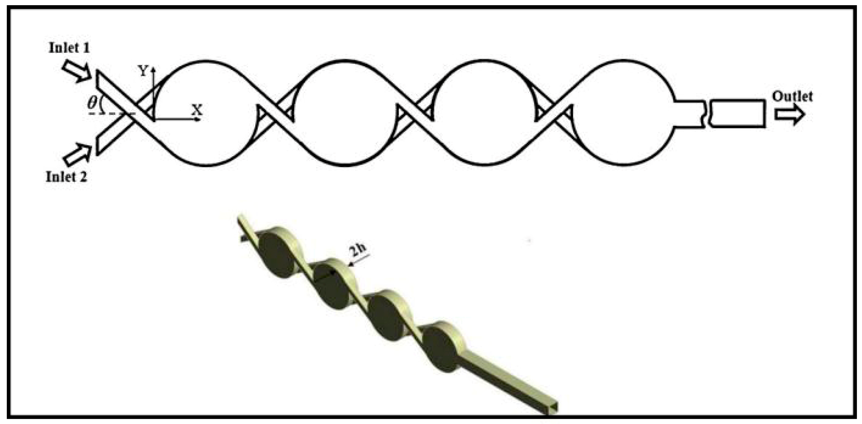
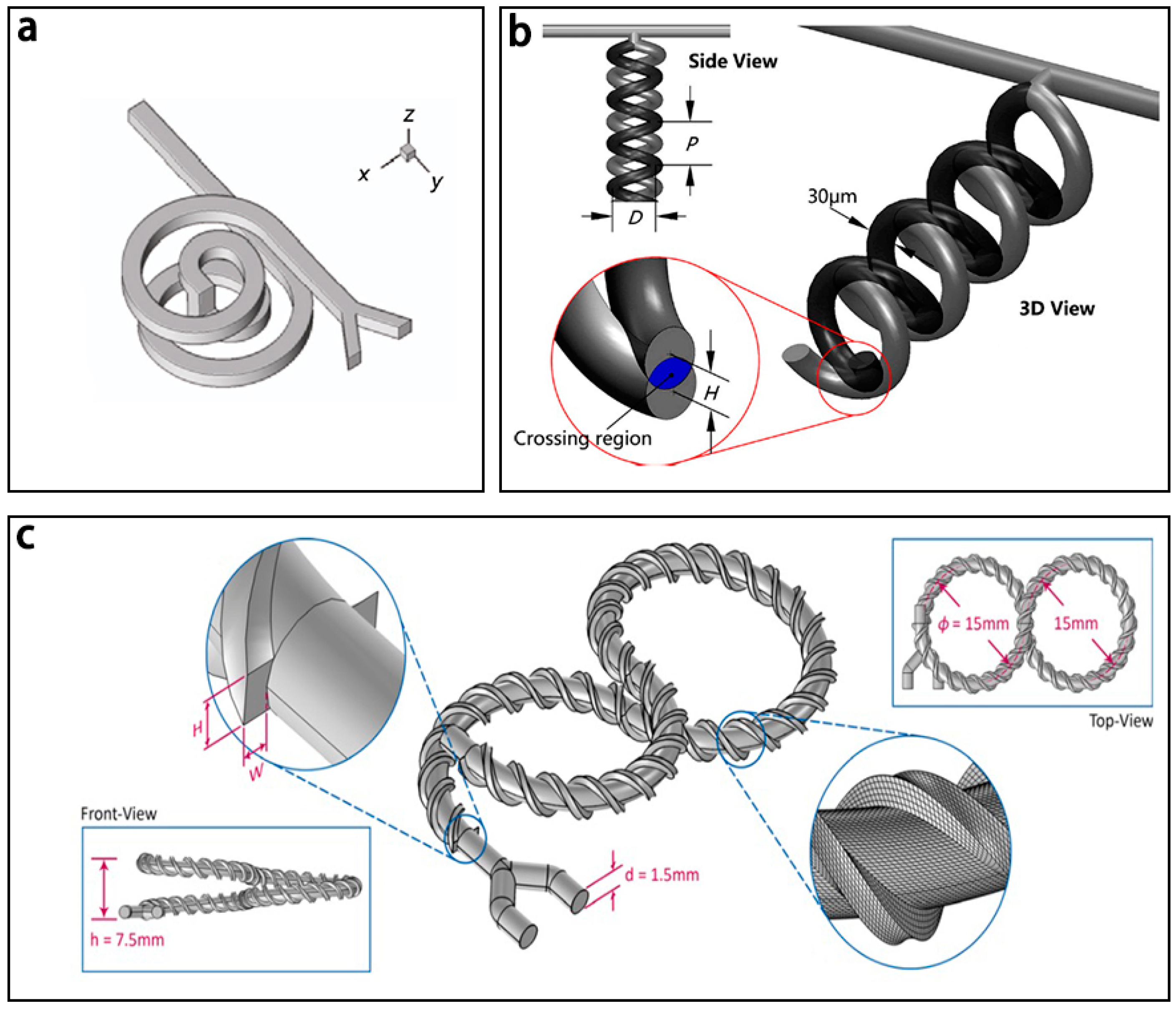
| 3D Spiral | Three dimensional spirals | 40 | 2340 | 90% 1 | [112] c | |
| Cross-linked dual helicals | 0.003–30 | 320 | 99% 2 | [113] a | ||
| Tapered structures | 50 | 10,500 | 90% 3 | [114] c | ||
| Overbridge | Overbridge-shaped channel | 0.01–50 | 2000 | 90% 4 | [115] c | |
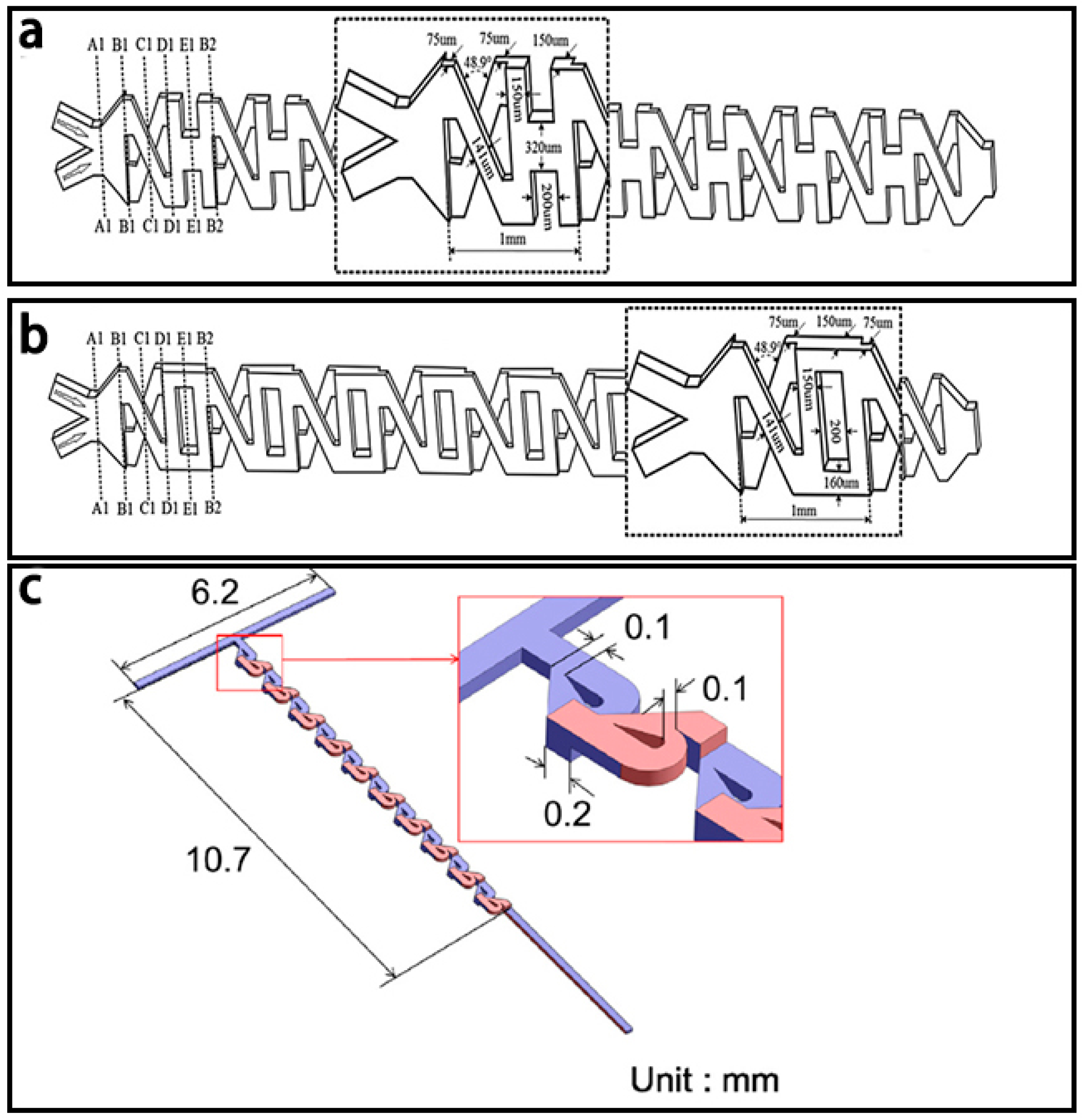
| Tesla structures | 0.1–100 | 10,700 | 94% 2 | [116] c | ||
| X-shape structures combined with H-shape structures | 0.3–60 | 102,500 | 87.7% 3 | [117] c | ||
| X-shape structures combined with O-shape structures | 0.3–60 | 102,500 | 72.9% 3 | [117] c | ||
| Serpentine crossing channels | 0.2–10 | 7500 | 99% 3 | [118] c |
© 2017 by the authors. Licensee MDPI, Basel, Switzerland. This article is an open access article distributed under the terms and conditions of the Creative Commons Attribution (CC BY) license (http://creativecommons.org/licenses/by/4.0/).
Share and Cite
Cai, G.; Xue, L.; Zhang, H.; Lin, J. A Review on Micromixers. Micromachines 2017, 8, 274. https://doi.org/10.3390/mi8090274
Cai G, Xue L, Zhang H, Lin J. A Review on Micromixers. Micromachines. 2017; 8(9):274. https://doi.org/10.3390/mi8090274
Chicago/Turabian StyleCai, Gaozhe, Li Xue, Huilin Zhang, and Jianhan Lin. 2017. "A Review on Micromixers" Micromachines 8, no. 9: 274. https://doi.org/10.3390/mi8090274