Review

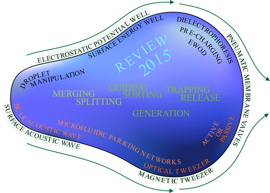
Droplet Manipulations in Two Phase Flow Microfluidics

Physics of Complex Fluids Group, MESA+ Institute, University of Twente, P.O. Box 217, 7500 AE Enschede, The Netherlands
*
Author to whom correspondence should be addressed.
Micromachines 2015, 6(11), 1768-1793; https://doi.org/10.3390/mi6111455
Submission received: 25 September 2015 / Revised: 3 November 2015 / Accepted: 6 November 2015 / Published: 13 November 2015
(This article belongs to the Special Issue Droplet Microfluidics: Techniques and Technologies)

Abstract

:
Even though droplet microfluidics has been developed since the early 1980s, the number of applications that have resulted in commercial products is still relatively small. This is partly due to an ongoing maturation and integration of existing methods, but possibly also because of the emergence of new techniques, whose potential has not been fully realized. This review summarizes the currently existing techniques for manipulating droplets in two-phase flow microfluidics. Specifically, very recent developments like the use of acoustic waves, magnetic fields, surface energy wells, and electrostatic traps and rails are discussed. The physical principles are explained, and (potential) advantages and drawbacks of different methods in the sense of versatility, flexibility, tunability and durability are discussed, where possible, per technique and per droplet operation: generation, transport, sorting, coalescence and splitting.

Graphical Abstract

1. Introduction

Droplet microfluidics has been around since the early 1980s, but the number of examples that have made it towards commercial applications are limited. In his 2006 overview, Whitesides [1] stated that microfluidics was still in its infancy, but might offer revolutionary new capabilities for the future. Indeed, great advances have been made since then, leading to commercial devices for genome sequencing, Polymerase Chain Reaction (PCR) and flow cytometry. Each of these techniques uses some form of microfluidics and droplet control for the automation of complex laboratory protocols.
The first tool required for droplet microfluidics is, of course, a system to generate droplets in the order of picoliter or even femtoliter [2] volumes. To generate a droplet, one needs a flow geometry (sometimes supplemented with an external field) that causes the continuous (mostly aqueous) phase to form a neck, followed by a break-up. This should preferably work in a highly controlled manner leading to a large continuous production of monodisperse droplets. Secondly, one or more methods of droplet manipulation are required, which force a droplet to execute the desired protocol. These methods do not necessarily have to be active. Some elegant passive methods have been developed for splitting [3,4], guiding [5] and trapping [5,6,7] drops at a certain location. Thirdly, most protocols require a certain type of analysis or detection, which mostly is optical (scattering, transmission, adsorption, fluorescence, Raman, surface plasmon resonance) or electrical (measuring current, voltage, impedance).
Over the years, several excellent reviews on droplet microfluidics have been published. There are short overviews on available techniques for droplet generation [8,9,10], methods for single cell encapsulation [11], passive microfluidic techniques [12], manipulations using electrowetting [13,14], as well as on the fundamental challenges involved [15], on the (need for) integration of biology, chemistry and physics in biological assays [16,17,18], on the choice of optimal surfactants [19], and even comprehensive review articles [20,21,22] and books [23] covering the entire field of droplet based microfluidics. The theoretical fluid physics aspects behind microfluidics have also been covered [24].
The present review is oriented towards techniques that have recently become available to manipulate the droplets in microchannels—both actively and passively. We try to give an impartial view of what are the advantages of each technique, and the downsides, as far as researchers are willing to divulge these. Some of these techniques are still in the academic research stage, waiting to be used for practical and commercial applications. This paper is further organized as follows: we first discuss the existing techniques from the physics point of view, and then separately how they have been translated to passive and active manipulations for which are able to execute laboratory protocols for biophysical and biochemical purposes.

2. Passive Manipulation Techniques

2.1. Drag Force and Viscous Dissipation

We define passive control as the use of a dedicated microfluidic geometry to control droplets entirely via the flow field, without any controller interference. In steady state flow the velocity of a droplet is governed by the drag exerted on the droplet by the continuous carrier medium. The terminal droplet velocity depends on how the two liquids flow through a channel. When a droplet is much smaller than the channel cross section the resulting terminal (i.e., steady state) velocity of the droplet equals the average local velocity of the continuous phase. In general, a small drop will follow the streamlines of the flow of the continuous phase. In Poiseuille flow, this means that droplets move faster in the center of the channel.
When droplets take up a larger portion of the channel cross section they are confined by two or four walls, resulting in the formation of lubrication films around the slug. As Baroud et al. [10] explain, the pressure drop ΔP across (and thus the terminal velocity of) slugs of droplets in a rectangular channel is influenced by corner flow of the continuous phase around the droplet. From this, it follows that not only viscosity and geometry play a role, but also the interfacial tension (thus deformability) influences the terminal velocity of the droplet. Using a microfluidic comparator, the influence of drop size, viscosity, interfacial tension and flow rate on the hydrodynamic resistance in a rectangular channel has been measured [25].
As an example, let us assume a confined droplet in a microchannel that only undergoes small deformations. This assumption is often valid in microchannels where the capillary number is very small and capillary forces (surface tension) dominate over viscous forces (viscosity and velocity). Such a droplet experiences a friction force due to the confinement, balanced by a drag force due to the surrounding flow field. The drag force exerted on such a droplet can be written as Fdrag = αLµvrel, with α a dimensionless prefactor determined by the geometry, L the characteristic length scale of the problem dependent on droplet radius and channel geometry, µ the dynamic viscosity, and vrel the continuous flow velocity relative to the dispersed phase. For an example of such a situation the reader could examine the supplementary information of [26], where the drag force on a droplet confined in a Hele-Shaw channel geometry in oil flow is described analytically.
When droplet deformations are no longer negligible, the relation between drag force and velocity is no longer linear because the deformation (and thus prefactor α) becomes velocity dependent. This brings us to another related factor that can influence droplet velocity: the presence of surfactants at the interface. The circulating flow fields inside and outside the slug can transport surfactants across the interface resulting in accumulation of surfactants at the rear of the droplet. This surfactant concentration gradient at the interface results in Marangoni stresses, leading to increased dissipation, slowing down the droplet. The interplay of these different mechanisms can make it difficult to predict the terminal velocity of a slug. For instance, in the presence of surfactants it can be possible for an air bubble to have a lower terminal velocity than a water droplet [3].
These basic insights can be helpful in designing passive control systems. As an example, one can use the different properties of droplets, and the resulting difference in drag forces exhibited on them, to change their behavior. For instance, drops of different viscosity will obtain a different terminal velocity. Partially confined, high viscosity droplets undergo a stronger viscous dissipation and therefore move slower than low viscosity droplets of equal radius (and confinement). This allows low viscosity droplets to catch up with high viscosity droplets, resulting in coalescence [27]. Similarly, droplets of different radius behave differently. In the regime of terminal velocity, a drop with smaller radius will move faster than a larger drop. This is because in Poiseuille flow the velocity of the continuous phase is higher near the center of the channel. Therefore a smaller droplet in the center of the channel will obtain a larger average velocity than a larger droplet. The same principle allows for the hydrodynamic separation of particles of different sizes [28]. In most cases however, droplets will neither have a different viscosity, nor a different size.

2.2. Geometric Structures

It is possible to design the geometry of a channel such that the flow field alters the drop behavior. For instance, the splitting of a droplet can be facilitated by dividing one channel into two branches, or using a pillar as a flow obstruction in the channel. Depending on channel widths and hydraulic resistances, this allows creating pairs of identical daughter droplets, or to split the volume of the mother droplet into a larger and a smaller fraction [4].
As shown by the Vanapalli group [29], so-called microfluidic parking networks can be used to let one droplet alter the flow field (and hence also the fate) for consecutive drops. When given the choice to enter different channels, a droplet will tend to follow the path of least hydraulic resistance. However, if that path contains a constriction much smaller than the droplet size, trapping of the droplet will occur, because the pressure drop over the parallel channel is smaller than the large Laplace pressure required to pass through the constriction. The droplet then effectively blocks that channel for consecutive droplets, forcing them to take the parallel channel. Depending on ratios of channel resistances a regime can be found where for instance every first drop is captured, or even regimes where the first droplet goes into the bypass channel, effectively increasing the resistance of this parallel channel, so that only the second or third droplet are captured. By letting consecutive drops coalesce, Bithi et al., also showed the ability to control the droplet volume accurately (Figure 5b), or change the (bio)molecular concentrations inside the droplet [7]. Other geometric structures, like an array of traps, can be built in a wide microchannel as well; in that case chance dictates the trapping of droplets (Figure 5a) [6].
Another great example of passive channel geometries has been shown by Korczyk et al., only by changing the flows their channel geometries are able to precisely meter a volume from a larger drop, merge droplets to create droplets of different concentration, delay a droplet and have a droplet shift register [30].

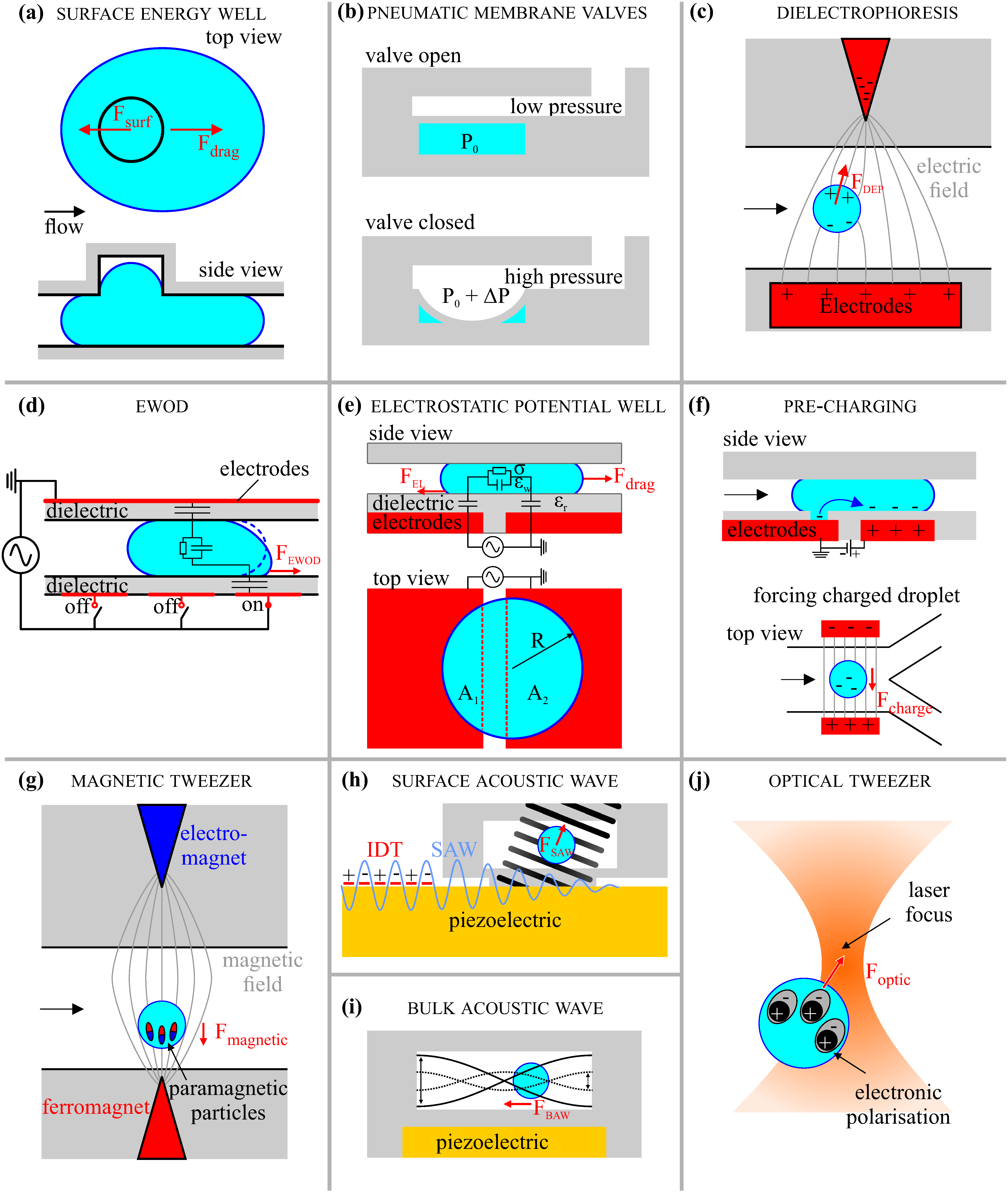
2.3. Surface Energy Wells

After a droplet is generated in a microchannel it is often confined by two walls and takes a pancake or disc shape. Alternatively, if it is confined by four walls, it becomes a slug. If there had been no walls (or other external forces) the droplet would have taken the shape of lowest surface energy, a sphere. Therefore it stands to reason that if the squeezed droplet was able to decrease its interfacial area that such change would be energetically favored. Creating a small hole in the top of a microchannel allows a drop to reduce its curvature, and thus its interfacial energy by locally expanding into the hole. Once a droplet is lodged in this surface energy well it will require force to pull it out (see Figure 1a). This makes it possible to trap a drop against the drag force [31], or split a droplet [32]. Building further on this idea, also thin trenches or “rails” were created, effectively creating elongated (directional) energy wells. These allow to steer a droplet in flow along these rails [33], or to fuse two droplets by using two converging rails [34]. Other researchers used similar rails for the fusion and sorting of droplets [35]. As is the case with other passive techniques: it is difficult to release the drop once trapped, or to select which way to steer a drop. Using active laser forcing (see Section 3.5) these problems can be overcome [5].
Figure 1. Schematic overview of the droplet manipulation techniques. (a) A squeezed droplet can decrease its interfacial energy by expanding in a hole; (b) Increasing the air pressure above the local water pressure expands the membrane into the crossing microchannel, effectively blocking it; (c) A polarizable medium will move towards the region with highest electric field intensity; (d) The electrostatic energy will be minimal when a droplet covers the activated electrode; (e) A droplet passing two electrodes finds a minimum energy when centered above the electrodes; (f) By taking charges from the open electrode, a droplet can be precharged. A precharged droplet will move towards the oppositely charged electrode; (g) Paramagnetic particles move towards the highest magnetic field strength and can drag a droplet along with them; (h) The interdigital transducer creates a surface acoustic wave that is attenuated at the PDMS pillar, creating an upward pressure wave that can move droplets; (i) At specific frequencies the piezo can create resonating pressure waves in a channel, forcing a droplet towards the antinodes; (j) A medium with better polarizability at optical frequencies than the surrounding medium will move towards the region of high intensity laser light.
Micromachines 06 01455 g001

3. Active Manipulation Techniques

Active manipulation entails changing the behavior or fate of a droplet (in flow) by an external, user-controlled mechanism. Below we discuss the more common techniques that are used for active control, selected on their proven ability to control droplets accurately and reliably. Our main focus will be on techniques that can control a droplet after it has been formed, but some of these techniques can also be used before or during droplet generation.

3.1. Pneumatic Membrane (Quake) Valves

A common material for fabrication of microfluidic devices is polydimethylsiloxane (PDMS), a polymer that can be molded using standard soft lithography techniques [36,37]. Multiple layers of PDMS are used as the basis for pneumatic membrane valves. One layer contains the microchannel structure through which the liquids will flow. Another layer consists of gas filled channels, which cross over the microchannel. At the point where the channels cross, the two layers are only separated by a thin PDMS membrane. By increasing the pressure of the gaseous phase the membrane expands into the liquid channel (see Figure 1b). When enough pressure is applied the liquid channel can be blocked, effectively forming a pneumatic valve [38]. This technique has been applied for creating a peristaltic pump [38], for the sorting of droplets [39], and for droplet generation [40]. Especially for droplet generation this technique has some advantages over other methods. Single droplets are generated on-demand, and the amplitude and duration of the pressure pulse can be used to control the size of the droplet [41]. Placing multiple droplet generators in series allows merging droplets of different content and size. In turn this enables the creation of large sets of droplets, covering wide ranges in concentrations and content [42]. Using many valves, such droplets can be individually guided and stored in a multiplex array of 95 wells for cell culturing or PCR analysis [43].

3.2. Electrical Techniques

3.2.1. Dielectrophoresis

Dielectropheresis (DEP) is the motion of polarizable objects caused by application of a non-uniform electric field. In microfluidics, DEP is mainly used to sort small particles with a different dielectric constant ϵ r than the surrounding medium [44]. There are multiple ways to understand how DEP works. For small droplets the easiest way to visualize DEP is to look at the charge distribution within the droplet. As we know, opposite charges attract. Thus, in an electric field any polarizable medium will orient its electric charges such that they oppose the electric field. Three main ways for a medium to polarize are: ionic, dipolar and electronic. If the medium contains ion pairs, like a salt dissolved in water, these can quickly shift the charges at the droplet interface. If the molecule is in itself a dipole, like a water molecule, it can rotate and orient itself against the electric field. Much faster, within each atom the positively charged nucleus and negative charged electron cloud can shift slightly to oppose the electric field.
Regardless of the polarization mechanism, the end result is a droplet that can be considered as a dipole which is oriented against the electric field. In an inhomogeneous field this means that the electrostatic attraction is larger at the side of the dipole where the electric field is stronger, resulting in a net force in the direction of increasing field strength (see Figure 1c). There are analytical expressions for the DEP force on spherical objects [45]. For different (droplet) shapes and volumes numerical modeling is needed to calculate the electric field and potential, and subsequently the DEP force.
In practical DEP applications an electric field inside a microfluidic channel is generally created by applying a voltage across two (or more) electrodes just outside the channel. A simple way to get gradients in the electric field is to use a pointed electrode where all the electric field lines converge. Especially interesting for two-phase flow microfluidics is that water droplets in an electric field can on average be considered as a large dipole. The consequence hereof is that not only small particles, but also water droplets in oil can be sorted with DEP, even at high speeds (>1 kHz) [46].
When dealing with larger volumes instead of dielectric droplets or particles, it can also be insightful to describe DEP (and electrowetting as well, see Section 3.2.2) via a capacitive energy approach. From electrostatics we know that when a voltage source charges a capacitor, the total electrostatic energy of the system decreases: E e l = 1 2 C U 2 with C the total lumped capacitance and U the applied potential. In microfluidic systems, a pair of electrodes next to a microchannel with either water, oil or another dielectric material in between also forms a capacitor. Since the electrostatic energy decreases with increasing capacitance, it is thermodynamically favorable to have a system with large capacitance. Using a lumped capacitance model, i.e., taking into account the capacitances of all different media between the electrodes, Eel can be calculated. The simplest case is a parallel plate capacitor, for which C = ϵ 0 ϵ r d A , with d the thickness of the dielectric between the electrodes and A the electrode area. Since displacement of the medium between the electrodes (e.g., oil) by one that has a higher polarizability (e.g., water) increases the lumped capacitance, it is energetically favorable for highly polarizable media to move towards the region of high electric field strength.

3.2.2. EWOD/DMF

In the context of microfluidics, ElectroWetting-On-Dielectric (EWOD) (also known as digital microfluidics, DMF) generally uses arrays of electrodes insulated by a thin dielectric layer to control conductive droplets [47]. This enables highly accurate, on-demand control over individual droplets like transportation, generation, splitting, coalescence and mixing [22].
The term electrowetting originates from the observation that a grounded water droplet atop an insulated electrode spreads when a voltage is applied, effectively decreasing the droplet contact angle with the substrate and thus “wetting the surface better”. This concept is explained by the Young-Lippmann model, which balances the surface energy cost with the gain in electrostatic energy when a droplet spreads. The model allows to calculate the (oil/water) interfacial tension, or the insulator thickness when measuring the contact angle as a function of voltage [48]. As an applied theoretical example the model also predicts the position of the droplet in an electrode wedge structure, dependent on applied voltage and the resulting droplet contact angle [49]. In droplet based microfluidics, however, it is difficult or even impossible to determine the contact angle. This makes application of the Young-Lippmann model less useful. To explain the droplet motion, it might be better to use an electrostatic model, in this case the same lumped capacitive model as mentioned before for DEP.
Although it is not always mentioned, EWOD is very similar to DEP [50]. Both techniques use the difference in response of the media to an applied electric field. One difference is that EWOD mainly uses aqueous droplets which are conductive due to the addition of ions. The high conductivity allows to consider the droplet as an electrode with resistance but negligible capacitance. This also makes a second difference between DEP and EWOD clear: the insulating layers are required to prevent the short circuiting of the electrodes. The continuous phase can be air, or an oil of low permittivity. In presence of a potential difference across electrodes but absence of a water droplet, the capacitance is intrinsically low. However, if the oil or air is replaced by a conductive drop, the total applied voltage now falls across the thin dielectric, insulating layers. The capacitance of the droplet can then be ignored, and the electrostatic energy of the system can be calculated using the a similar formula as before: E e l = 1 2 ϵ 0 ϵ r d A U 2 , but now with d being the total thickness of the insulating layers, not the distance between electrodes. By switching on an electrode from the array of electrodes, the droplet will find a minimum energy by spreading across the activated electrode, increasing its capacitive area. The resulting force pulls on the three-phase contact line allowing to move droplets (see Figure 1d).
To further show the similarity between DEP and EWOD, the conductive liquid in EWOD can be described with an effective permittivity ϵ e f f = ϵ r 2 + σ 2 ω 2 , with σ the conductivity and ω the applied voltage frequency. At low conductivity or high frequency ϵ e f f reduces to ϵ r . This means that the water droplet can no longer be considered as a perfect conductor, and thus that the capacitance of the aqueous phase can no longer be neglected. Since the dielectric constant of the water phase must be taken into account EWOD has effectively become DEP.
The main advantage of EWOD is the sheer number of droplet manipulations that are possible on-demand. The fact that it works well with conductive droplets makes it ideal for biological and cell applications. Another advantage of EWOD is that it is a relatively basic electromechanical technique, which ensures that the control over water droplets is accurate, switchable, high speed and predictable. EWOD can be integrated in more complex (control) systems by using state-of-the-art techniques from the immense field of electronics. Nice examples are for instance the ability to print electrodes on thin films, allowing the manipulation of droplets on bent surfaces [51]. In addition, real-time detection of the droplet position by measuring the capacitance of a set of electrodes [52], or electronic paper displays [53] illustrate this point. Thin film transistor arrays used in liquid crystal displays have also been used for EWOD, giving control to over 4000 electrodes with impedance spectroscopy for droplet position detection [54].
There are also some disadvantages to consider when using EWOD. One is the high voltage that is required for thick dielectric layers. Another is that relatively complex electronic systems are required when using many individually activated electrodes. The longevity of a device is also strongly dependent on the dielectric materials used. Many different materials have been used aiming for good hydrophobicity, low hysteresis and high resistance to dielectric breakdown. Some researchers have focused on making the dielectric as thin as possible, to allow use of low voltages. This would make EWOD compatible with standard low voltage electrical systems (no need for expensive amplifiers and switches), while still allowing for high speed droplet actuation [55]. Others have used relatively porous dielectrics like PDMS which are infused with the continuous oil phase, ensuring low hysteresis and sufficient hydrophobicity [26,56]. It is interesting to see how an open source project like DropBot brings researchers together to make EWOD cheaper, automated, more reliable and effectively crossing the divide between laboratory research and commercial application [57].

3.2.3. Electrostatic Potential Wells

EWOD devices are mostly used as large arrays of electrodes that completely control every motion of each droplet. In an attempt to acquire the strengths of both worlds, the high throughput of two-phase flow channel-based microfluidics has been combined with the individual drop control achieved using electrical actuation [26]. Two-phase flow allows for high-speed droplet generation and the transport of droplets over large distances without the need for many electrodes. By having dielectric covered electrodes below the microchannel, the accurate on-demand control of EWOD is used to manipulate (conductive) aqueous droplets in flow. A disadvantage, as compared to EWOD alone, is that the ability to transport droplets upstream is lost.
The electrode geometries in this technique are chosen to be co-planar electrodes separated by a gap that is comparable to the thickness of the dielectric layer. When a potential is applied across such a gap, a passing droplet will try to equalize the areas of droplet contact above the electrodes since this maximizes the lumped capacitance. Effectively the electrodes form an energy well, where the electrostatic energy is minimal if the droplet centers over the gap (see Figure 1e). The similarity with surface energy wells (Section 2.3) is clear, and therefore this method was coined “electrostatic potential wells”. The technique has been able to trap, coalesce and release droplets in flow, split a droplet in two equal volumes, guide droplets to different lateral positions on electrostatic rails [26], and sort droplets at >1 kHz [58].

3.2.4. Pre-Charging

A third electrostatic manipulation technique that needs to be mentioned is the pre-charging of droplets. Several ways for pre-charging droplets have been described in literature. One method applies a DC electric field perpendicular to the flow in the channel. The positive and negative charges (ions) in the droplet separate to either side of the droplet. While the charges are separated the water droplet is split in two at the crossing of a T-junction, resulting in two oppositely charged water droplets [59]. A second method uses two closely spaced electrodes below the channel. A positive or negative DC voltage is applied across the electrodes as a droplet passes and covers both electrodes. An opposite charge q is induced in the droplet at the active, insulated electrode interface. The charges originate from the grounded electrode that has no insulating layer (see Figure 1f). The charges remain in the droplet as it detaches from the electrodes resulting in a charged droplet [60].
Charging a droplet in itself has little use. A secondary electrode pair further downstream the channel is required to apply another electric field. In this second electric field charged droplets will feel an electric force F e = q E , with E the electric field strength. Negatively charged droplets move towards the positively charged electrodes and vice versa. This technique is capable of sorting of pre-charged droplets into three different outlet channels at 3 drops per second [61]. A secondary utilization of this technique arises from the coalescence of droplets. Two oppositely charged droplets will feel an attractive electrostatic force enabling an easier coalescence of droplets, even when the droplets are covered by surfactants [59].

3.3. Magnetic Manipulations

Similar to DEP where polarizable materials are influenced by an electric field, so can magnetic particles be manipulated by a magnetic field. One example is the magnetic tweezer (see Figure 1g). Here, an electromagnet above the channel in combination with a ferromagnet built in the substrate below the channel generate a magnetic field with increasing intensity towards the ferromagnet. Paramagnetic particles inside droplets will orient to oppose the magnetic field and move towards the region of high magnetic field strength. In some cases the particles are able to drag a droplet with them, which allows the movement of a droplet. In other cases the particles are extracted from the droplet and later merged with a consecutive droplet. By functionalizing the particles, for instance with antibodies, this allows the execution of biological assays [62,63].
By integrating stripes of paramagnetic PDMS below a microfluidic channel, magnetic field gradients can be created around the stripes by providing an external, homogeneous magnetic field. Water droplets loaded with paramagnetic microparticles will then move towards the stripes, where the magnetic field gradient is highest. This technique provides an energy landscape very similar to the surface energy rails and the electrostatic potential rails, discussed in Section 2.3 and Section 3.2.3, and has been used to guide and sort droplets in oil flow along the rails and trap and merge droplets at the end of the magnetic rail [64]. Similarly, rotating external magnetic fields have been used to let ferrofluidic droplets perform automatic tasks, effectively creating logic gates (see Section 4.6) [65].

3.4. Acoustic Waves

3.4.1. Surface Acoustic Waves

As the name suggests, a surface acoustic wave (SAW) is an acoustic pressure wave that propagates across a substrate. It is created by interdigitated electrodes on a piezo-electric substrate. The resonance frequency of the interdigitated transducer (IDT) depends on the pitch between the electrodes and the characteristic velocity at which a sound wave travels across a specific surface material. When a potential is applied over the IDT at the resonance frequency a high pressure Rayleigh wave of MHz frequency and nanometer amplitudes is created, which propagates across the substrate. An encounter with a fluidic channel attenuates the wave by coupling its energy into the fluid. This results in a (standing or travelling) bulk pressure wave propagating through the liquid at an angle (the Rayleigh angle) that is determined by the differences in acoustic impedance (material density and wave speed) of the media. This bulk wave can generate an acoustic radiation force on droplets or cause acoustic streaming within a liquid. The first manipulates droplets, the latter influences particles in flow.
While the technique for creating SAWs has been demonstrated in the 1960s [66], it has only recently been rediscovered as a means for external control in microfluidics. Firstly, for the focusing of beads [67], and soon after for the sorting of droplets [68]. Very recently the technique has been used for steering of slugs [69]. By using a tapered electrode geometry localized pressure fields can be created in the channel. In this local field a droplet can be trapped temporarily and then merged with a consecutive droplet [70,71]. Another way to localize the region where the pressure wave will occur is by using a PDMS pillar to connect the IDT substrate with the channel (see Figure 1h). Only at the pillar the SAW will be attenuated and form an upwards pressure wave. This clever design allowed the sorting of droplets containing cells from empty droplets at a rate of 3 kHz [72]. Combining multiple tapered IDTs with multiple pillars enables the sorting towards multiple outlet channels. Besides forcing individual droplets, the SAWs are also capable of providing enough pressure to break up a thin co-flowing stream of water in oil. This enabled to generate cell-containing droplets directly from co-flow [72].
Numerical simulations can be used to predict the acoustic field in a channel [72], and the displacement of a surface by the SAW can be measured using Laser Doppler vibrometry [70]. Recently, another optical technique has been developed which is able to measure the acoustic field in a microchannel directly [73]. Advantages of SAW are that only small voltages are required to create very large forces, and that pressure waves will manipulate any object in the channel, independent of permittivity, conductivity, refractive index or size. A disadvantage could be that the brute force from SAWs is not localized and SAWs are therefore not convenient for highly accurate control. Within these limits it is still possible to perform several protocols that do require accuracy, like splitting [71] a droplet in two, by using multiple IDTs and carefully tuned voltage actuation sequences.

3.4.2. Ultrasonic Acoustophoresis

Besides SAWs it is of course also possible to create bulk acoustic waves by simply using a flat piezo-electric surface in contact with the channel walls, instead of the interdigitated transducer. This directly creates bulk acoustic waves (BAWs) in the microchannel. Unlike SAWs, BAWs are restricted to discrete, harmonic resonance modes such that the wavelength fits the channel dimension (see Figure 1i). If a particle or droplet is large enough it will move towards the nearest anti-node. This allows to sort large objects from small particles. BAWs have also been used for stretching and mixing of droplets [74], as well as for sorting and coalescing droplets [75].

3.5. Optical Manipulation Techniques

The use of focused laser spots generates various possibilities for droplet manipulation. Light waves can interact with objects in different ways. A focused light beam is in fact nothing more than an electric field gradient with the highest field strength in the center. Very similar to how dielectric objects respond to an electric field, as described in Section 3.2.1, so do objects of high permittivity move towards the center of the highest electric field strength created by the laser. The difference is that electric field frequency for laser light lies in the order of 1014 Hz. The orientational and ionic polarization mechanisms of molecules cannot follow these frequencies and the permittivity thus only depends on the electronic screening abilities of the atoms. Perhaps the best-known example of this principle are optical tweezers (see Figure 1j) [76]. A collimated laser beam enters an infinity-corrected objective lens and is focused into a narrow beam in the focal plane. This focal spot is used to trap and transport a high permittivity particle or droplet. By changing the angle at which the collimated beam enters the objective the focal spot is translated laterally, while changing the incoming beam to slightly diverging or converging translates the focal spot axially. The technique is not limited to just water of course, but can for instance also manipulate liquid crystals [77], as long as there is a gradient in refractive index. To be able to manipulate multiple droplets or particles, multiple individually changeable beam wave fronts are required. Towards this end, spatial light modulators have been used to create up to 400 dynamically addressable optical tweezers [78]. A disadvantage of optical manipulation techniques is that the absolute force that can be generate is quite low in the order of 100 pN or lower [79]. This means optical techniques are probably only useful at low flow rates.
Electrostatic interaction is not the only influence light has on particles. Light waves also refract at the interface of a spherical particle of different refractive index than the surrounding medium. And because photons are known to have momentum this means that photons which are scattered or absorbed actually transfer this momentum to the particle or droplet and force it in the direction of laser beam propagation, as well as towards the beam center. This principle makes it possible to selectively sort droplets towards different outlets [80]. To prevent optical trapping of the particle, the laser beam is not focused.
A different method to use focused laser light to manipulate droplets is using the light to locally heat the interface of surfactant covered droplets. This heating increases the local interfacial tension of the droplet, probably by removing or destroying the surfactant, effectively creating an interfacial tension gradient at the droplet interface. As a result Marangoni flows are created around the laser hot spot yielding a force that pushes the droplet away from the hot spot. This technique has been used for influencing droplet generation, coalescence and fusion [81]. It also has been used in combination with the passive surface energy wells described in Section 2.3 to transport droplets from one rail to another, and to dislodge trapped droplets from their surface energy trap [5].
The final optical technique worth mentioning is used for on-demand generation of droplets by using intense pulsed laser light to create rapidly expanding cavitation vapor bubbles [82]. The cavity comes to existence when the strong optical field induces breakdown of the water molecules, forming plasma. The energy quickly dissipates and the heat generated in this process creates a quickly expanding cavity vapor bubble of which the pressure wave moves through the water and perturbs a nearby oil-water interface. The water pushes into the oil phase to form an aqueous droplet. Droplet generation rates of up to 10 kHz and droplet volumes of 1–150 pL were realized. The authors report volume deviations of just 1%, which would make this technique one of the most accurate ways for droplet generation.

4. Required Manipulations

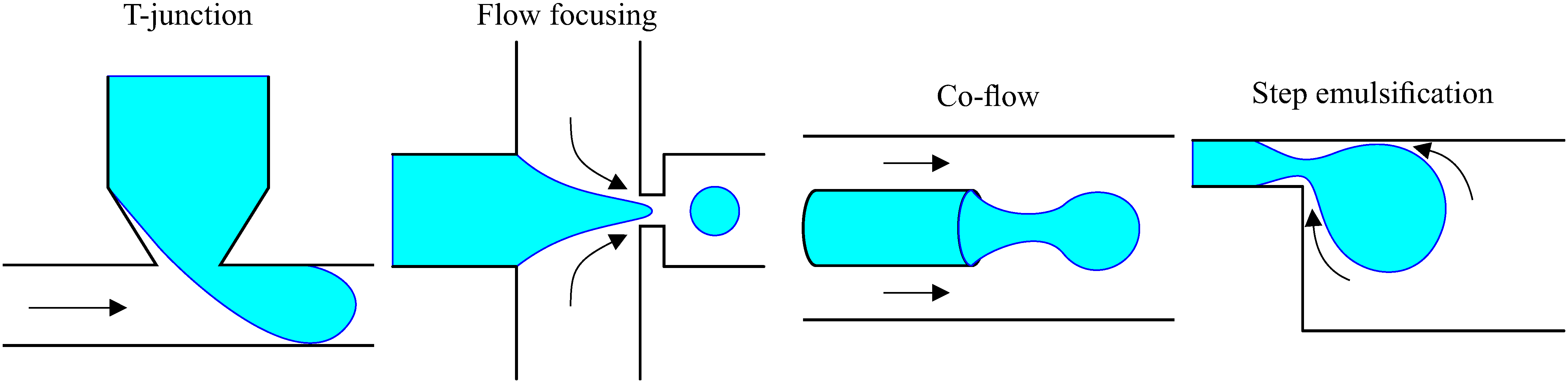
4.1. Droplet Generation

The creation of droplets is the basis of any two-phase flow microfluidic chip [8,9,10]. Especially in the early days of droplet microfluidics, many different channel designs have been thought of to generate droplets. Most common techniques are based on hydrodynamic interaction between the two immiscible phases, where the continuous phase applies shear on the eventually dispersed phase. See Figure 2 for an overview of such flow based techniques.
Figure 2. Schematic representation of the most popular droplet generation methods. Black arrows indicate the flow direction of the continuous phase.
Micromachines 06 01455 g002
One option is the T-junction [83], where two perpendicular channels bring the two phases together. When the front of the dispersed phase fluid intrudes into the main channel, a pressure drop occurs between the front and rear of the emerging droplet. The droplet grows under the balance of pressure, interfacial tension and shearing force until the neck at the rear becomes thin enough—and the pressure low enough—to break into a small droplet [84]. In practice, the T-junction creates slugs of droplets in the exiting channel with a minimal length of twice the channel width, or larger if the pressure in the dispersed phase channel is increased. Smaller droplet sizes can be obtained at higher flowrates, but these are generated by a Plateau-Rayleigh instability, which is generally not considered to be the best method to create monodisperse droplets.
Another option for generating droplets is the flow focusing device (FFD) [85]. In an FFD the dispersed phase is located in a center channel while the continuous phase enters from two perpendicular side channels. In this way, the dispersed phase is squeezed between the two continuous phase flows. By shear stress a neck is formed and broken from the dispersed phase creating a droplet. Often a smaller orifice through which all the liquids must flow is positioned behind the FFD. This creates a high local shear stress at the orifice, which ensures the neck is broken in this region. In practice, droplet size and generation frequency are influenced by the FFD geometry, the viscosities of the two phases and the flowrates. The droplet sizes are more uniform as compared to techniques that use the Plateau-Rayleigh instability to break the neck. Droplet generation frequencies can go up to several kHz.
Very similar to the FFD, drops can also be generated by a co-flowing geometry [86]. In this geometry a thin (glass) capillary or (metal) needle is inserted as a center channel inside the main channel. The dispersed phase—often water since it wets the glass capillary well—enters via the capillary and is segmented by the shear force of the external continuous fluid on the dispersed phase. At higher flowrates a jet is formed and droplet break up is again caused by Plateau-Rayleigh instability [87]. One advantage is that the dispersed phase is completely surrounded by the continuous phase. This ensures that the dispersed phase does not interact with the channel walls, which can significantly increase the durability of the microfluidic channel when using biological media. Another advantage is the ability to create double or even triple emulsions-inside-emulsions [88].
Another method is called step emulsification [89,90]. This technique is based on the fact that a soon-to-be-dispersed liquid filling a thin channel is always confined by the (non-wetting) side walls. A confined liquid is forced into strong curvature, resulting in a large Laplace pressure drop across the interface. If a region is offered where the channel expands in both width and height (a step) the tip of the water phase will accelerate into the wider channel to decrease its high curvature. As it accelerates a neck is formed behind the droplet as the continuous phase flows upwards in the channel [91]. When the neck has become thin enough, it eventually breaks due to Rayleigh-Plateau instability. The step can also be a gradual change in height where the gradient influences the eventual droplet size [34]. The step emulsification method has the advantage that the drop size is mainly controlled by the geometry and the resulting change in Laplace pressure, and less influenced by pressure differences between the liquid phases. This allows parallelizing the step geometry, and thus generates a high throughput of reasonably uniform droplets [34,89].
Active control over the droplet generation frequency can easily be achieved by changing the flow rates or pressures of the liquid phases. A very elegant technique for actively controlling the droplet generation frequency is dielectrophoresis (DEP) [92]. By applying a high-frequency voltage across four electrodes positioned around the FFD an electrostatic force is applied on the water interface. Increasing the voltage increases this force, pulling the water interface further downstream in the FFD and effectively increasing the droplet generation frequency. Compared to syringe pumps, electrical control allows for much faster switching between generation frequencies.
So far, the discussed techniques generate continuous streams of drops. To generate single droplets on-demand active control is required. Firstly, the dispersed phase has to be static for this application. This can be achieved by stopping the flow, but in case of syringe pumps, control can be hindered by elastic effects from the tubing and is therefore not very fast or stable. A simpler approach is to use a pressure controller for the dispersed liquid phase. Stopping the soon-to-be-dispersed liquid phase can be facilitated by using a tapered channel: as the liquid traverses through the tapering channel, its curvature increases. Ultimately the increasing Laplace pressure will match the applied pressure on the liquid phase, causing the flow to stop. By applying a short pressure pulse a droplet can be generated on demand. Other active methods for on demand drop generation include electrowetting [13,93,94], SAWs [95], pneumatic valves [41,96,97] and laser-induced cavitation [82]. A nice feature of the pneumatic valves is that consecutive pneumatically controlled droplet generators can directly combine different solutions into one droplet at controllable ratios [42].

4.2. Droplet Transport/Guiding/Steering

In some protocols it is required to transport a droplet to a specific location, for instance towards a position where it should be held for incubation, or where it can be analyzed by some optical technique, or the starting location of another protocol on the same chip. Both passive and active techniques have been devised to transport droplets in the desired direction. Arguably the most accurate technique that offers external, on-demand control over droplet transport is EWOD. Protocols for electrode actuation can be preset, but also changed by the user depending on what is needed. Optical tweezers are able to trap a droplet in the focal waist and by moving the focal spot the droplet can be transported.
The simplest passive technique for droplet transport is to let it follow the flow of the continuous phase. Microfluidic walls or obstructions determine where a droplet goes. More interesting are manipulation techniques that can be used in combination with flow. In Section 2.3, surface energy rails were discussed that can passively guide droplets, assisted by flow. Inspired by the simple physics behind these surface energy rails, electrostatic potential rails have been designed to actively guide droplets towards six different lateral positions in a wide channel, depending on which electrodes are activated (See Figure 3) [26]. An intricate network of microchannels and pneumatic valves has been used to direct flows of drops towards 95 wells independently [43].
Figure 3. (a) Guiding of droplets by surface energy rails. The laser spot is used to select and force droplets onto the rail. A local widening of the rail serves as a deeper surface energy well where trapping will occur. A droplet can be pushed out of the well by a consecutive droplet. Adapted from [5] with permission of The Royal Society of Chemistry; (b) Guiding of droplets by electrostatic potential rails. Depending on which electrodes are activated a droplet will be guided towards one of six lateral positions in the channel. Adapted from [26] with permission of The Royal Society of Chemistry.
Micromachines 06 01455 g003

4.2.1. Droplet Sorting

The sorting of droplets is perhaps the most important application in microfluidics, especially for chemical or biological applications. Most researchers use fluorescence detection to determine whether a droplet should be sorted or not, called fluorescence assisted droplet sorting (FADS). Whether it is a fluorescently labeled cell in a droplet that needs to be separated from empty droplets, or proof whether a chemical reaction has taken place, fluorescence is an easy-to-use and fast technique enabling detection at high speeds.
The sorting of droplets is actually a subset of guiding droplets, so all previous techniques for active droplet transport can be used for sorting as well. Albeit a relatively slow process, the surface energy rails achieved active sorting control by laser forcing [5]. In addition, the novel method of magnetic rails has room for improvement at sorting rates of four drops per minute. Pre-charging of droplets allowed to sort droplets at 3 Hz so far [61]. Standing SAWs have been shown to reach sorting frequencies of 222 Hz [98]. By using a pneumatic valve to close the waste outlet (with low hydrodynamic resistance) droplets can be sorted towards the other outlet at 250 Hz [39]. The electrostatic energy rails have been converted into a smaller electrode geometry allowing for active sorting at 1200 Hz [58]. As mentioned before DEP was one of the first applied, active sorting techniques for droplets [46], later improved with another electrode geometry and laser detection to accomplish active sorting up to 2000 Hz [99]. But the technique that is able to apply the largest force on a droplet is the travelling SAW, able to sort at 3000 Hz [72]. It must be noted that not all experiments have been done on comparable droplet systems. For instance the electrostatic energy rails used droplets with a two times larger radius than the DEP experiments, approximately multiplying the drag force that needs to be overcome by four. For the travelling SAW experiments, the authors also claim that the maximum applied force was not limited by the technique itself, but by the fact that more force could harm the droplet content. See Figure 4 for an overview of drop sorting.
Figure 4. Active sorting of droplets. (a) Magnetic particles in droplets force the droplet towards the magnetic rail when a magnetic field is applied over the entire chip. With kind permission from Springer Science+Business Media: Microfluidics and Nanofluidics, Selective handling of droplets in a microfluidic device using magnetic rails. 2015, 19, 1, 141–153, Teste et al. [64]; (b) Applying a pressure to the pneumatic valve changes the path of least resistance from the upper to the lower channel. Reprinted with permission from [39]. Copyright 2014, AIP Publishing LLC; (c) Depending on the frequency of the SSAW droplets will be forced towards one of the five outlets. Adapted with permission from [98]. Copyright 2013, American Chemical Society; (d) By switching on or off the central electrode the electrostatic potential rails will force a droplet to the upper or lower channel. Adapted with permission from [58]. Copyright 2015, AIP Publishing LLC; (e) By activating the electrode (red) an electric field gradient is created forcing water droplets to the upper channel. In the inset the droplets go to the lower channel by default. Adapted from [99] with permission of The Royal Society of Chemistry; (f) Left: The IDT generates a SAW, which is attenuated at the PDMS pillar. This locally creates a upwards pressure wave that forces a droplet to the upper channel. Right: Using two IDTs and two pillars allows to sort to multiple outlets. Adapted from [72] with permission of The Royal Society of Chemistry.
Micromachines 06 01455 g004

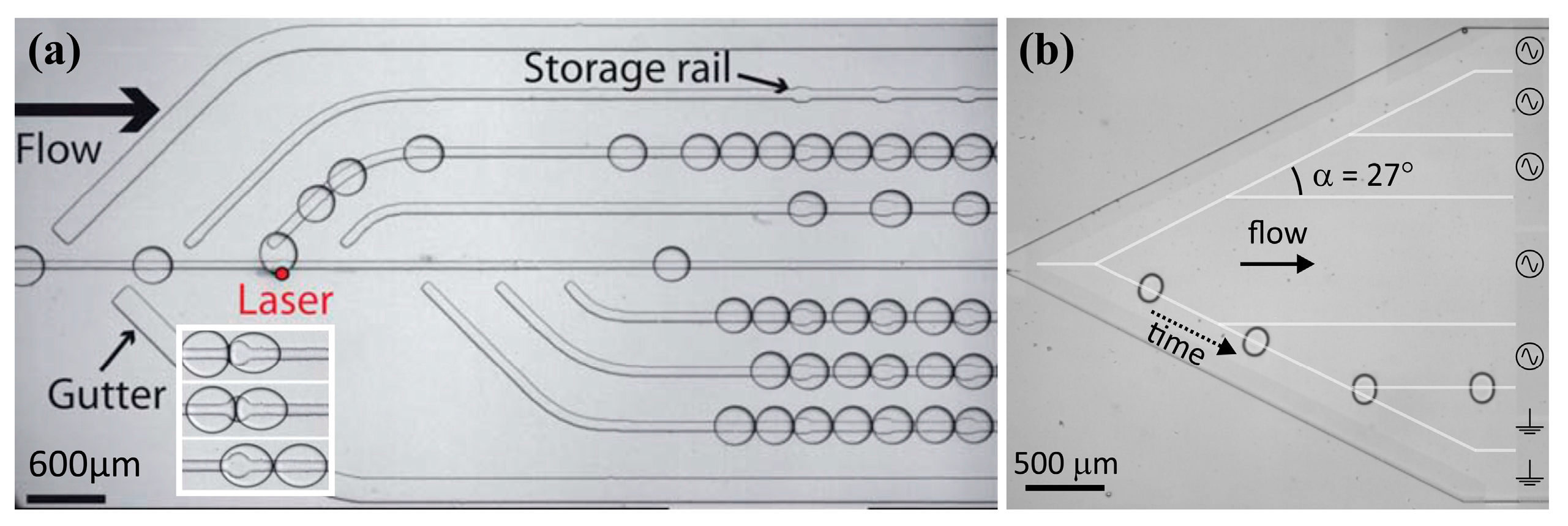
4.3. Droplet Trapping and Release

Holding droplets at a specific location in a microchip during flow can be used for several protocol steps. One step could be an incubation, where a droplet needs to wait for a chemical or biological process to reach completion. Or a step where droplets need to be analyzed over a longer time, which is easier if the droplets are not moving. As an example one could think of following the interaction kinetics of a (droplet based) protein to a ligand bound on one of the channel walls, using the change in refractive index near the surface as the signal (e.g., using SPR).
Optical tweezers can be used to trap one droplet at a time, and a two-electrode geometry is able to create an energy well and hold a droplet using DEP [100]. Here, however, only the more practical trapping techniques are mentioned, specifically the ones that are able to trap multiple droplets simultaneously which should allow for multiplex assays. For practical reasons, like re-using a chip or analyzing droplets off-chip, it is also useful to be able to release a droplet after analysis is complete.
Geometrical structures are the simplest method of trapping droplets [6]. The microfluidic parking networks are a typical example of a passive, geometrical technique for trapping droplets at specific on-chip locations [29]. Concentration gradients of trapped droplets can be created, and the trapped volume can also be rectified [7]. Releasing of the droplets is not mentioned by the authors, but could perhaps be possible by reversing the flow.
Arrays of surface energy wells (holes in the microchip substrate) have shown their ability to trap multiple drops [33]. One disadvantage is that the trapping is determined by chance and thus non-specific. This issue has been resolved by combining the traps with surface energy rails and laser forcing, allowing to select which droplets will be trapped at which position on the chip. The success of this method was demonstrated via the creation of an array of trapped droplets with increasing concentration gradient [5]. The droplets can be released by increasing the flow rate [31], which can also break up the droplet, leaving behind a controlled volume in the trap [32], or, as before, the droplet can be actively released by laser forcing [5].
An intricate network of microchannels and pneumatic valves has been used to route flows through the microchannels and selectively guide droplets towards 95 wells. The droplets can be loaded one by one, and as the authors mention, their chip allows for automated cross-contamination free release and recovery of the reaction products from the individual chambers for downstream analysis. Combined with the ability to easily create concentration gradients of droplet content, this technique can be very useful for automating multiplex laboratory protocols [43].
It is clear that EWOD is intrinsically capable of trapping and release, since it controls all motions of the droplet. The only flow-based technique shown to be able to trap and release multiple droplets on demand without the need for geometric obstructions is the electrostatic potential well. By applying a potential over two channel-wide electrodes separated by a zigzagging gap, droplets can be trapped at each lateral location where the gap forms a tip. Upstream the electrostatic potential rails are used to transport droplets laterally in the channel towards the desired trapping location. The angle of the zigzag structure ensures that a droplet is corrected for errors in lateral position. One zigzagging electrode geometry forms a column where six drops can be trapped on-demand by switching just one electrode. Releasing of the six droplets is simply done by turning off the active electrode. By placing multiple zigzagging structures after another arrays of droplet traps are created [26]. Figure 5 shows an overview of the discussed trapping techniques.
Figure 5. Overview of trapping mechanisms of droplets in oil flow. (a) Array of passive geometric traps. Reversing the oil flow releases the droplets. Adapted from [6] with permission of The Royal Society of Chemistry; (b) Array of multiple, consecutive microfluidic parking networks of different volume. Reprinted with permission from [7]. Copyright 2014, AIP Publishing LLC; (c) Surface energy wells, for trapping droplets and release by laser forcing. Adapted from [5] with permission of The Royal Society of Chemistry; (d) Top: Gradients of droplet content created and guided by pneumatic membrane valves to 95 individually addressable traps. Bottom: Magnification of the passive trapping geometry. Adapted with permission from [43]. Copyright 2012, National Academy of Sciences, USA; (e) Left: Three different electrode geometries for electrostatic potential wells. Right: Six by six electrostatic potential well arrays for the trapping and release of 36 droplets. Adapted from [26] with permission of The Royal Society of Chemistry.
Micromachines 06 01455 g005

4.4. Droplet Splitting/Fission

The on-chip splitting of droplets could have several purposes. For instance if the volume of a droplet needs to be reduced, or if a protocol requires two identical droplets of which one for instance serves as the blank/control experiment. The first requires the asymmetric splitting of a droplet in controlled volume ratios, the second requires the splitting in two equally sized droplets. Since water in air or oil has a relatively high surface tension sometimes surfactants are added to the oil and/or water phase to reduce the interfacial tension, which facilitates droplet splitting.
Basically, each technique used for the generation of droplets (Section 4.1) is capable of breaking up the droplet phase. Pneumatic valves can break up an existing droplet while it passes, or a flow focusing junction with smaller orifice or higher continuous flow rate can break a droplet into multiple smaller drops.
Many passive break up methods use a combination of flow and geometric structures. Splitting slugs of droplets can be done by dividing a channel in two, so a droplet can break up at the T-junction. Breakup can be facilitated by adding a pointy structure to the T-junction [3]. The volume ratios can be predetermined by having different hydrodynamic resistances of either outlet channel. Very similarly, a pillar obstruction in the channel can split droplets. Again changing the relative pathway resistances by placing the pillar off-center determines the volume ratio of the split droplets [4]. An overview of splitting techniques is given in Figure 6.
Active techniques capable of splitting droplets are quite rare. EWOD is good example for the splitting into equally sized droplets, even without need for surfactants [13,101]. By activating 3 (or more) electrodes in a row a droplet will be elongated. Deactivation of the center electrode ensures the droplet wants to reduce its contact area with that particular electrode, while still being pulled towards the outer electrodes. This results in the droplet splitting in two equal volumes, or in discrete volume ratios depending on how many, and which electrodes used. Similarly the electrostatic potential wells have also been able to split a droplet in two equal volumes [26].
Figure 6. Overview of splitting methods. (a) Two off-axis IDTs create two SAWs that apply a torque on a 3 µL droplet, splitting it in two. Adapted from [71] with permission of The Royal Society of Chemistry; (b) Passively, using a multiple consecutive T-junctions, a slug can be split into 16 equal sized droplets. Reproduced from [3] with permission of The Royal Society of Chemistry; (c) Top: A pillar in the center of a channel splits droplets into equal volumes. Bottom: An off-center pillar splits droplets in unequal volumes. Reprinted with permission from [4]: Link et al., Phys. Rev. Lett. 2004, 92, 054503. Copyright 2004 by the American Physical Society; (d) By activating a row of three EWOD electrodes a drop will elongate. After deactivating the central electrode, a bridge is formed, splitting the droplet in two equal volumes. Copyright 2003 IEEE. Reprinted, with permission, from [13]; (e) Similar to EWOD, a droplet in oil flow will split in two equal volumes if the voltage across the electrostatic potential rails is high enough. The drag force assists in the breakup of the neck. Reproduced from [26] with permission of The Royal Society of Chemistry.
Micromachines 06 01455 g006
SAWs can be used for droplet splitting as well. By using two off-axis IDTs on either side of a droplet SAWs can be created that apply a torque on the droplet. Low amplitude SAWs enable the stretching or rotation of a droplet. When followed by higher amplitude SAWs a droplet can be split in two [71]. Depending on the ratio of amplitudes of each SAW it is possible to alter the eventual volume ratio of the split droplets. It must be noted that in this case the droplets were in the order of microliters, and not the more conventional picoliter range in droplet microfluidics.

4.5. Droplet Merging/Coalescence/Fusion

Many protocols require the merging of droplets, e.g., two droplets with different content coalescing in order to start or stop a chemical reaction, or to dilute a sample [9]. Passive techniques are available to aid in droplet coalescence. A simple passive approach is to widen the microchannel, and thus reducing the flow rate locally. This effectively reduces the distance between two consecutive droplets and promotes coalescence when the channel width is reduced once more [102]. Theoretically, all that is required for droplets to coalesce is to bring them close together, and wait for the thin film between droplets to be squeezed out. Therefore any technique that can transport or trap droplets (Section 4.2 and Section 4.3) is capable of bringing two drops together and merge them. For instance optical forcing [103] and SAW [70] have been used to trap a droplet until a secondary droplet flows against it. Optical tweezers have been used to fuse two femtoliter droplets together [104], while the more powerful SAW technique has also been used to push two microliter sized drops together [71].
Figure 7. Overview of droplet merging techniques. (a) Merging two microliter sized droplets using two SAWs focused by a tapered electrode geometry. Adapted from [71] with permission of The Royal Society of Chemistry; (b) Electrocoalescence of two cell-containing, surfactant-covered droplets, while travelling through the electric field created by two electrodes as indicated by the dashed triangles. Coalescence frequency is > 1 kHz. Adapted with permission from [107]. Copyright 2014 by John Wiley & Sons Inc., Hoboken, NJ, USA; (c) EWOD electrode geometry used to bring two droplets together after splitting. Copyright 2003 IEEE. Reprinted, with permission, from [13]; (d) After trapping two surfactant-covered droplets with different content in surface energy wells, they are merged using a laser spot focused at the droplet-droplet interface. Adapted from [5] with permission of The Royal Society of Chemistry; (e) Similar to electrocoalescence, interdigitated electrodes below a microchannel will merge two surfactant-covered droplets within milliseconds. Adapted with permission from [93]. Copyright 2011, AIP Publishing LLC.
Micromachines 06 01455 g007
Frequently, and especially in biological applications, surfactants are added to the oil and/or water phase, which separates droplets and helps to ensure that each droplet is one small reaction container less influenced by neighboring droplets. Surfactants can also mitigate wetting problems, and can provide a means for exchanging small molecules between droplets through the continuous phase [19]. Specifically fluorinated surfactants can create highly stable emulsions and are capable of storing droplet emulsions for multiple years [105]. To still be able to coalescence these surfactant stabilized droplets an external force that destabilizes the interface is required. For instance, as a chemical method an extra inlet for a destabilizing alcohol can locally increase the chance of coalescence [106]. As a passive method, gaseous bubbles have been placed in between multiple water droplets of different content, serving to separate trains of droplets. Since a confined gaseous bubble moves slower through a channel than the surfactant covered water droplets, the water droplets are pushed together. Over time the thin oil film between the droplets is squeezed out and the droplets coalesce [3]. Active coalescence is mostly achieved by electrical actuation (electrocoalescence). First, two droplets are brought in close proximity for instance by the channel geometry. By using a DEP-like electrode geometry, two droplets in an electric field will polarize and charges accumulate at the surface. At the interface between the droplets the charges are opposite (if the droplet pair is aligned in the direction of the electric field), which results in an electrostatic force that brings the droplets closer together. The thin oil film is squeezed out until the droplets merge. Applying a high frequency (kHz) electric field perturbs the interface between the droplets increasing the efficacy of merging [107]. In the same manner for EWOD and electrostatic potential wells two droplets have to be brought towards neighboring electrodes and the AC frequency of the applied voltage helps to destabilize the interface and speeds up the coalescence of droplets [13]. Interdigitated electrode structures are capable of merging surfactant covered droplets on-demand within milliseconds [93]. Surface energy wells have also been used to trap two surfactant covered, highly stabilized droplets. Laser forcing was required to break the interface and merge the droplets [5]. See Figure 7 for an overview of the discussed droplet merging techniques.

4.6. Droplet Logics

So far, in all active techniques the external control is governed by computers and electronics. Understandably so, since digital logics offer fast and reliable actuation. It could, however, make sense to build (part of) the logics into the microfluidic chip, where the presence or state of one drop is influenced by the state of other droplets, or the state of the chip. Theoretically, this could allow droplets to perform more complex routines automatically and determined by the current state of the microfluidic device. As an example, pneumatic membrane valves have been used to open and close different channels and force droplets to execute a certain protocol depending on which valves are activated or not [108]. This allowed the creation of NOT, NAND and NOR gates, flip-flops, oscillators, self-driven peristaltic pumps, and a 12-bit shift register. Another method generates gas bubbles in the channel, and uses the hydrodynamic interaction between bubbles to automatically perform logic operations, forming AND/OR/NOT gates, a toggle flip-flop, a ripple counter, timing restoration and a ring oscillator [109]. As a purely passive technique, a channel geometry has been designed that serves as a shift register for water droplet in oil [110,111]. Very recently, ferrofluidic droplets atop a substrate incorporating multiple permalloy geometries were shown to automatically perform logic operations when a continuous rotating magnetic field is applied [65]. This enabled AND, OR, XOR, NOT and NAND logic gates, fanouts, a full adder, a flip-flop and a finite-state machine without any external control. Specifically the interaction of serial and parallel logic gates could be useful in droplet microfluidics to perform the required protocols.

5. Discussion/Conclusions

One protocol step that is not extensively covered in this review is mixing. The homogenization of droplets with volumes in the picoliter regime generally requires ~1 s, assuming a molecular diffusivity of 5 × 10⁻¹⁰ m2/s, as is typical for small molecules. And that is not taking into account internal flows inside the droplet that are created by velocity gradients at the interface. It has been shown that droplets traversing a channel can passively mix within 25 ms [112]. Faster passive mixing (within 2 ms) can be achieved by letting the droplet traverse a meandering channel: mixing is then further enhanced by the internal flow patterns [113,114]. Active mixing could be achieved through application of an AC voltage, either in EWOD or in DEP. EWOD droplet mixers using electrode arrays have been demonstrated in closed chips [115], while perturbation of the interface of a sessile droplet was found to enhance mixing as well [116].
The absolute forces in surface energy wells are comparatively small, which limits the operation speeds. However, the technique is easily understood, easily implemented in microfluidic devices and, perhaps its best attribute, passive. This makes the surface energy wells very cheap to implement, since no expensive peripheral equipment (pressure regulators, amplifiers, data acquisition cards, laser optics etc.) are required.
EWOD (DMF) is a technique that offers the most versatile control, being able to perform all protocol steps mentioned in this review. It is also one of the more powerful techniques. The durability of EWOD still appears to be an “Achilles heel”, where dielectric breakdown or wetting can occur during prolonged application of high voltages. In general, DEP has the electrode geometry outside the channel, and therefore does not have such issues with durability. This geometry does however require (much) higher voltages, and cannot generate forces as large as with EWOD. Moreover, with DEP, it is not possible to perform each of the protocol steps.
SAW offers the largest forces from all techniques discussed, making it stand out as a powerful technique for sorting. Perhaps more focus could be put on making the high intensity pressure fields more localized in the channel, e.g., in a range comparable to the droplet radius, to obtain more precise control for the more subtle protocol requirements like splitting or trapping.
Pneumatic membrane valves offer an entirely different way of implementing the required protocol steps. The valves are capable of performing all the drop manipulations discussed in this review. Specifically the ability to actively change the flow direction of the continuous phase is quite unique as an active control method. One downside of the membrane valves is that they are generally an order of magnitude slower in operation than the electronically actuated methods of drop manipulation.
Optical techniques in general offer much smaller forces than the other techniques. Increasing the light intensity can generate larger forces, but also causes heating inside the liquid. Still, this heating can be used to generate droplets at high rates, or to assist in the coalescence of droplets. The use of focused laser light has also been demonstrated to be effective for several manipulations in case of surfactant covered droplets.
In short, many different methods have been devised to manipulate droplets in microchannels, each with their own specific (and sometimes inherent) advantages and drawbacks. We have given an overview of techniques that are well-established by now, and of methods which we currently consider to be amongst the most promising or ingenious. For many applications it would be desirable to use only passive techniques; each droplet would then simply execute its process without any need for outside control or feedback. Unfortunately, for the more complicated protocols that is simply impossible and external control is required. It is up to the chip designer to decide which technique will suit his purposes best, finding the optimum between the technique’s possibilities, actuation speed, power, accuracy, reliability, ease-of-use, safety and costs. Table 1 gives an overview of the specific positive and negative aspects of each technique.
In some cases, high performance applications have been realized by combining multiple techniques, as exemplified by the combination of (passive) surface energy wells and (active) laser forcing, or (active) EWOD and (passive) two-phase flow. EWOD (active) has also been combined with antibody-coated paramagnetic particles (active) for the execution of complex immunoassays [117]. The combination of (passive) microfluidic parking networks with (active) pneumatic membrane valves has resulted in parking networks with active control for merging, storage and release while reducing the number of required pneumatic valves [118]. More of such developments towards high standard lab-on-a-chip applications can be expected, since none of the mentioned techniques seem to limit the application of another technique.
Table 1. Overview of the techniques discussed in this review and their capabilities.
TechniqueGeneral AttributesDroplet GenerationDroplet Manipulation
ActivePowerControl/AccuracyDurabilityCostFrequencyOn DemandControlGuidingSortingTrappingSplittingCoalescing
Passive (flow based)N+ ++/−+ ++ ++ +− −++− −+/−+ ++
Passive (pressure based)N+ +++ ++ ++ ++ ++ ++− −+/−+ ++
Surface energyN+/−+ ++ +− −− −− −++/−+ +++ +
Pneumatic valvesY++ +++/−++ ++ ++ +++ ++ ++ +
DEPY+ +++++ ++ +++ ++/−+/−+
EWOD/DMFY+ ++ +++ ++ ++ +++ ++ ++ +
Electrostatic potential wellsY+ ++ +++ ++ ++ ++ ++ ++ ++ +
Pre-chargingY++++++− −+ +
MagneticY++/−++/−++++/−+
SAWY+ + ++++++/−++ + +++/−+
BAWY+++++− −+
OpticalY+/−+++ ++ ++ ++++/−+

Acknowledgments

We specifically thank Dirk van den Ende for his insightful contributions to the discussion about drag force and viscous dissipation. This research was supported by the Dutch Technology Foundation STW, which is part of the Netherlands Organization for Scientific Research (NWO), and which is partly funded by the Ministry of Economic Affairs.

Conflicts of Interest

The authors declare no conflict of interest.

References

  1. Whitesides, G.M. The origins and the future of microfluidics. Nature 2006, 442, 368–373. [Google Scholar] [CrossRef] [PubMed]
  2. Leman, M.; Abouakil, F.; Griffiths, A.D.; Tabeling, P. Droplet-based microfluidics at the femtolitre scale. Lab Chip 2015, 15, 753–765. [Google Scholar] [CrossRef] [PubMed]
  3. Um, E.; Rogers, M.E.; Stone, H.A. Combinatorial generation of droplets by controlled assembly and coalescence. Lab Chip 2013, 13, 4674–4680. [Google Scholar] [CrossRef] [PubMed]
  4. Link, D.R.; Anna, S.L.; Weitz, D.A.; Stone, H.A. Geometrically mediated breakup of drops in microfluidic devices. Phys. Rev. Lett. 2004, 92, 054503. [Google Scholar] [CrossRef] [PubMed]
  5. Fradet, E.; McDougall, C.; Abbyad, P.; Dangla, R.; McGloin, D.; Baroud, C.N. Combining rails and anchors with laser forcing for selective manipulation within 2D droplet arrays. Lab Chip 2011, 11, 4228–4234. [Google Scholar] [CrossRef] [PubMed] [Green Version]
  6. Huebner, A.; Bratton, D.; Whyte, G.; Yang, M.; deMello, A.J.; Abell, C.; Hollfelder, F. Static microdroplet arrays: A microfluidic device for droplet trapping, incubation and release for enzymatic and cell-based assays. Lab Chip 2009, 9, 692–698. [Google Scholar] [CrossRef] [PubMed]
  7. Bithi, S.S.; Wang, W.S.; Sun, M.; Blawzdziewicz, J.; Vanapalli, S.A. Coalescing drops in microfluidic parking networks: A multifunctional platform for drop-based microfluidics. Biomicrofluidics 2014, 8, 034118. [Google Scholar] [CrossRef] [PubMed]
  8. Chen, J.S.; Jiang, J.H. Droplet Microfluidic Technology: Mirodroplets Formation and Manipulation. Chin. J. Anal. Chem. 2012, 40, 1293–1300. [Google Scholar] [CrossRef]
  9. Gu, H.; Duits, M.H.G.; Mugele, F. Droplets Formation and Merging in Two-Phase Flow Microfluidics. Int. J. Mol. Sci. 2011, 12, 2572–2597. [Google Scholar] [CrossRef] [PubMed]
  10. Baroud, C.N.; Gallaire, F.; Dangla, R. Dynamics of microfluidic droplets. Lab Chip 2010, 10, 2032–2045. [Google Scholar] [CrossRef] [PubMed]
  11. Collins, D.J.; Neild, A.; deMello, A.; Liu, A.Q.; Ai, Y. The Poisson distribution and beyond: Methods for microfluidic droplet production and single cell encapsulation. Lab Chip 2015, 15, 3439–3459. [Google Scholar] [CrossRef] [PubMed]
  12. Solvas, X.C.; deMello, A. Droplet microfluidics: Recent developments and future applications. Chem. Commun. 2011, 47, 1936–1942. [Google Scholar] [CrossRef] [PubMed]
  13. Cho, S.K.; Moon, H.J.; Kim, C.J. Creating, transporting, cutting, and merging liquid droplets by electrowetting-based actuation for digital microfluidic circuits. J. Microelectromech. Syst. 2003, 12, 70–80. [Google Scholar] [CrossRef]
  14. Kaler, K.; Prakash, R. Droplet Microfluidics for Chip-Based Diagnostics. Sensors 2014, 14, 23283–23306. [Google Scholar] [CrossRef] [PubMed]
  15. Mugele, F. Fundamental challenges in electrowetting: From equilibrium shapes to contact angle saturation and drop dynamics. Soft Matter 2009, 5, 3377–3384. [Google Scholar] [CrossRef]
  16. Guo, M.T.; Rotem, A.; Heyman, J.A.; Weitz, D.A. Droplet microfluidics for high-throughput biological assays. Lab Chip 2012, 12, 2146–2155. [Google Scholar] [CrossRef] [PubMed]
  17. Takinoue, M.; Takeuchi, S. Droplet microfluidics for the study of artificial cells. Anal. Bioanal. Chem. 2011, 400, 1705–1716. [Google Scholar] [CrossRef] [PubMed]
  18. Theberge, A.B.; Courtois, F.; Schaerli, Y.; Fischlechner, M.; Abell, C.; Hollfelder, F.; Huck, W.T.S. Microdroplets in Microfluidics: An Evolving Platform for Discoveries in Chemistry and Biology. Angew. Chem. Int. Ed. 2010, 49, 5846–5868. [Google Scholar] [CrossRef] [PubMed]
  19. Baret, J.C. Surfactants in droplet-based microfluidics. Lab Chip 2012, 12, 422–433. [Google Scholar] [CrossRef] [PubMed]
  20. Seemann, R.; Brinkmann, M.; Pfohl, T.; Herminghaus, S. Droplet based microfluidics. Rep. Prog. Phys. 2012, 75, 016601. [Google Scholar] [CrossRef] [PubMed]
  21. Song, H.; Chen, D.L.; Ismagilov, R.F. Reactions in droplets in microfluidic channels. Angew. Chem. Int. Ed. Engl. 2006, 45, 7336–7356. [Google Scholar] [CrossRef] [PubMed]
  22. Choi, K.; Ng, A.H.C.; Fobel, R.; Wheeler, A.R. Digital Microfluidics. Annu. Rev. Anal. Chem. 2012, 5, 413–440. [Google Scholar] [CrossRef] [PubMed]
  23. Day, P.; Manz, A.; Zhang, Y. Microdroplet Technology: Principles and Emerging Applications in Biology and Chemisty; Springer: New York, NY, USA, 2012. [Google Scholar]
  24. Bruus, H. Theoretical Microfluidics; Oxford Master Series in Physics; Oxford University Press: Oxford, UK, 2008. [Google Scholar]
  25. Vanapalli, S.A.; Banpurkar, A.G.; van den Ende, D.; Duits, M.H.G.; Mugele, F. Hydrodynamic resistance of single confined moving drops in rectangular microchannels. Lab Chip 2009, 9, 982–990. [Google Scholar] [CrossRef] [PubMed]
  26. De Ruiter, R.; Pit, A.M.; de Oliveira, V.M.; Duits, M.H.G.; van den Ende, D.; Mugele, F. Electrostatic potential wells for on-demand drop manipulation in microchannels. Lab Chip 2014, 14, 883–891. [Google Scholar] [CrossRef] [PubMed]
  27. Jin, B.J.; Kim, Y.W.; Lee, Y.; Yoo, J.Y. Droplet merging in a straight microchannel using droplet size or viscosity difference. J. Micromech. Microeng. 2010, 20, 035003. [Google Scholar] [CrossRef]
  28. Blom, M.T.; Chmela, E.; Oosterbroek, R.E.; Tijssen, R.; van den Berg, A. On-chip hydrodynamic chromatography separation and detection of nanoparticles and biomolecules. Anal. Chem. 2003, 75, 6761–6768. [Google Scholar] [CrossRef] [PubMed]
  29. Bithi, S.S.; Vanapalli, S.A. Collective dynamics of non-coalescing and coalescing droplets in microfluidic parking networks. Soft Matter 2015, 11, 5122–5132. [Google Scholar] [CrossRef] [PubMed]
  30. Korczyk, P.M.; Derzsi, L.; Jakiela, S.; Garstecki, P. Microfluidic traps for hard-wired operations on droplets. Lab Chip 2013, 13, 4096–4102. [Google Scholar] [CrossRef] [PubMed]
  31. Dangla, R.; Lee, S.; Baroud, C.N. Trapping microfluidic drops in wells of surface energy. Phys. Rev. Lett. 2011, 107, 124501. [Google Scholar] [CrossRef] [PubMed]
  32. Amselem, G.; Brun, P.T.; Gallaire, F.; Baroud, C.N. Breaking Anchored Droplets in a Microfluidic Hele-Shaw Cell. Phys. Rev. Appl. 2015, 3, 054006. [Google Scholar] [CrossRef]
  33. Abbyad, P.; Dangla, R.; Alexandrou, A.; Baroud, C.N. Rails and anchors: Guiding and trapping droplet microreactors in two dimensions. Lab Chip 2011, 11, 813–821. [Google Scholar] [CrossRef] [PubMed]
  34. Dangla, R.; Kayi, S.C.; Baroud, C.N. Droplet microfluidics driven by gradients of confinement. Proc. Natl. Acad. Sci. USA 2013, 110, 853–858. [Google Scholar] [CrossRef] [PubMed]
  35. Xu, L.F.; Lee, H.; Panchapakesan, R.; Oh, K.W. Fusion and sorting of two parallel trains of droplets using a railroad-like channel network and guiding tracks. Lab Chip 2012, 12, 3936–3942. [Google Scholar] [CrossRef] [PubMed]
  36. McDonald, J.C.; Duffy, D.C.; Anderson, J.R.; Chiu, D.T.; Wu, H.; Schueller, O.J.; Whitesides, G.M. Fabrication of microfluidic systems in poly(dimethylsiloxane). Electrophoresis 2000, 21, 27–40. [Google Scholar] [CrossRef]
  37. Duffy, D.C.; McDonald, J.C.; Schueller, O.J.; Whitesides, G.M. Rapid Prototyping of Microfluidic Systems in Poly(dimethylsiloxane). Anal. Chem. 1998, 70, 4974–4984. [Google Scholar] [CrossRef] [PubMed]
  38. Unger, M.A.; Chou, H.P.; Thorsen, T.; Scherer, A.; Quake, S.R. Monolithic microfabricated valves and pumps by multilayer soft lithography. Science 2000, 288, 113–116. [Google Scholar] [CrossRef] [PubMed]
  39. Abate, A.R.; Agresti, J.J.; Weitz, D.A. Microfluidic sorting with high-speed single-layer membrane valves. Appl. Phys. Lett. 2010, 96, 203509. [Google Scholar] [CrossRef]
  40. Lee, W.S.; Jambovane, S.; Kim, D.; Hong, J.W. Predictive model on micro droplet generation through mechanical cutting. Microfluid. Nanofluid. 2009, 7, 431–438. [Google Scholar] [CrossRef]
  41. Zeng, S.J.; Li, B.W.; Su, X.O.; Qin, J.H.; Lin, B.C. Microvalve-actuated precise control of individual droplets in microfluidic devices. Lab Chip 2009, 9, 1340–1343. [Google Scholar] [CrossRef] [PubMed]
  42. Jambovane, S.; Kim, D.J.; Duin, E.C.; Kim, S.K.; Hong, J.W. Creation of Stepwise Concentration Gradient in Picoliter Droplets for Parallel Reactions of Matrix Metalloproteinase II and IX. Anal. Chem. 2011, 83, 3358–3364. [Google Scholar] [CrossRef] [PubMed]
  43. Leung, K.; Zahn, H.; Leaver, T.; Konwar, K.M.; Hanson, N.W.; Page, A.P.; Lo, C.C.; Chain, P.S.; Hallam, S.J.; Hansen, C.L. A programmable droplet-based microfluidic device applied to multiparameter analysis of single microbes and microbial communities. Proc. Natl. Acad. Sci. USA 2012, 109, 7665–7670. [Google Scholar] [CrossRef] [PubMed]
  44. Cetin, B.; Li, D. Dielectrophoresis in microfluidics technology. Electrophoresis 2011, 32, 2410–2427. [Google Scholar] [CrossRef] [PubMed] [Green Version]
  45. Pethig, R. Review article-dielectrophoresis: Status of the theory, technology, and applications. Biomicrofluidics 2010, 4, 022811. [Google Scholar] [CrossRef] [PubMed]
  46. Ahn, K.; Kerbage, C.; Hunt, T.P.; Westervelt, R.M.; Link, D.R.; Weitz, D.A. Dielectrophoretic manipulation of drops for high-speed microfluidic sorting devices. Appl. Phys. Lett. 2006, 88, 024104. [Google Scholar] [CrossRef]
  47. Mugele, F.; Baret, J.C. Electrowetting: From basics to applications. J. Phys. Condens. Matter 2005, 17, R705–R774. [Google Scholar] [CrossRef]
  48. De Ruiter, R.; Wennink, P.; Banpurkar, A.G.; Duits, M.H.; Mugele, F. Use of electrowetting to measure dynamic interfacial tensions of a microdrop. Lab Chip 2012, 12, 2832–2836. [Google Scholar] [CrossRef] [PubMed]
  49. Baratian, D.; Cavalli, A.; van den Ende, D.; Mugele, F. On the shape of a droplet in a wedge: New insight from electrowetting. Soft Matter 2015, 11, 7717–7721. [Google Scholar] [CrossRef] [PubMed]
  50. Jones, T.B. On the relationship of dielectrophoresis and electrowetting. Langmuir 2002, 18, 4437–4443. [Google Scholar] [CrossRef]
  51. Abdelgawad, M.; Freire, S.L.S.; Yang, H.; Wheeler, A.R. All-terrain droplet actuation. Lab Chip 2008, 8, 672–677. [Google Scholar] [CrossRef] [PubMed]
  52. Bhattacharjee, B.; Najjaran, H. Droplet sensing by measuring the capacitance between coplanar electrodes in a digital microfluidic system. Lab Chip 2012, 12, 4416–4423. [Google Scholar] [CrossRef] [PubMed]
  53. Hayes, R.A.; Feenstra, B.J. Video-speed electronic paper based on electrowetting. Nature 2003, 425, 383–385. [Google Scholar] [CrossRef] [PubMed]
  54. Hadwen, B.; Broder, G.R.; Morganti, D.; Jacobs, A.; Brown, C.; Hector, J.R.; Kubota, Y.; Morgan, H. Programmable large area digital microfluidic array with integrated droplet sensing for bioassays. Lab Chip 2012, 12, 3305–3313. [Google Scholar] [CrossRef] [PubMed]
  55. Banerjee, A.N.; Qian, S.Z.; Joo, S.W. High-speed droplet actuation on single-plate electrode arrays. J. Colloid Interface Sci. 2011, 362, 567–574. [Google Scholar] [CrossRef] [PubMed]
  56. Caputo, D.; de Cesare, G.; lo Vecchio, N.; Nascetti, A.; Parisi, E.; Scipinotti, R. Polydimethylsiloxane material as hydrophobic and insulating layer in electrowetting-on-dielectric systems. Microelectron. J. 2014, 45, 1684–1690. [Google Scholar] [CrossRef]
  57. Fobel, R.; Fobel, C.; Wheeler, A.R. DropBot: An open-source digital microfluidic control system with precise control of electrostatic driving force and instantaneous drop velocity measurement. Appl. Phys. Lett. 2013, 102, 193513. [Google Scholar] [CrossRef]
  58. Pit, A.M.; de Ruiter, R.; Kumar, A.; Wijnperlé, D.; Duits, M.H.G.; Mugele, F. High-throughput sorting of drops in microfluidic chips using electric capacitance. Biomicrofluidics 2015, 9, 044116. [Google Scholar] [CrossRef] [PubMed]
  59. Link, D.R.; Grasland-Mongrain, E.; Duri, A.; Sarrazin, F.; Cheng, Z.D.; Cristobal, G.; Marquez, M.; Weitz, D.A. Electric control of droplets in microfluidic devices. Angew. Chem. Int. Ed. 2006, 45, 2556–2560. [Google Scholar] [CrossRef] [PubMed]
  60. Ahn, B.; Lee, K.; Panchapakesan, R.; Oh, K.W. On-demand electrostatic droplet charging and sorting. Biomicrofluidics 2011, 5, 024113. [Google Scholar] [CrossRef] [PubMed]
  61. Rao, L.; Cai, B.; Wang, J.L.; Meng, Q.F.; Ma, C.; He, Z.B.; Xu, J.H.; Huang, Q.Q.; Li, S.S.; Cen, Y.; et al. A microfluidic electrostatic separator based on pre-charged droplets. Sens. Actuators B Chem. 2015, 210, 328–335. [Google Scholar] [CrossRef]
  62. Ali-Cherif, A.; Begolo, S.; Descroix, S.; Viovy, J.L.; Malaquin, L. Programmable Magnetic Tweezers and Droplet Microfluidic Device for High-Throughput Nanoliter Multi-Step Assays. Angew. Chem. Int. Ed. 2012, 51, 10765–10769. [Google Scholar] [CrossRef] [PubMed]
  63. Teste, B.; Ali-Cherif, A.; Viovy, J.L.; Malaquin, L. A low cost and high throughput magnetic bead-based immuno-agglutination assay in confined droplets. Lab Chip 2013, 13, 2344–2349. [Google Scholar] [CrossRef] [PubMed]
  64. Teste, B.; Jamond, N.; Ferraro, D.; Viovy, J.L.; Malaquin, L. Selective handling of droplets in a microfluidic device using magnetic rails. Microfluid. Nanofluid. 2015, 19, 141–153. [Google Scholar] [CrossRef]
  65. Katsikis, G.; Cybulski, J.S.; Prakash, M. Synchronous universal droplet logic and control. Nat. Phys. 2015, 11, 588–596. [Google Scholar] [CrossRef]
  66. White, R.M.; Voltmer, F.W. Direct Piezoelectric Coupling to Surface Elastic Waves. Appl. Phys. Lett. 1965, 7, 314–316. [Google Scholar] [CrossRef]
  67. Shi, J.J.; Mao, X.L.; Ahmed, D.; Colletti, A.; Huang, T.J. Focusing microparticles in a microfluidic channel with standing surface acoustic waves (SSAW). Lab Chip 2008, 8, 221–223. [Google Scholar] [CrossRef] [PubMed]
  68. Franke, T.; Abate, A.R.; Weitz, D.A.; Wixforth, A. Surface acoustic wave (SAW) directed droplet flow in microfluidics for PDMS devices. Lab Chip 2009, 9, 2625–2627. [Google Scholar] [CrossRef] [PubMed]
  69. Sesen, M.; Alan, T.; Neild, A. Microfluidic plug steering using surface acoustic waves. Lab Chip 2015, 15, 3030–3038. [Google Scholar] [CrossRef] [PubMed]
  70. Sesen, M.; Alan, T.; Neild, A. Microfluidic on-demand droplet merging using surface acoustic waves. Lab Chip 2014, 14, 3325–3333. [Google Scholar] [CrossRef] [PubMed]
  71. Collignon, S.; Friend, J.; Yeo, L. Planar microfluidic drop splitting and merging. Lab Chip 2015, 15, 1942–1951. [Google Scholar] [CrossRef] [PubMed]
  72. Schmid, L.; Weitz, D.A.; Franke, T. Sorting drops and cells with acoustics: Acoustic microfluidic fluorescence-activated cell sorter. Lab Chip 2014, 14, 3710–3718. [Google Scholar] [CrossRef] [PubMed]
  73. Oever, J.V.T.; Frentrop, R.; Wijnperlé, D.; Offerhaus, H.; van den Ende, D.; Herek, J.; Mugele, F. Imaging local acoustic pressure in microchannels. Appl. Opt. 2015, 54, 6482–6490. [Google Scholar] [CrossRef] [PubMed]
  74. Cheung, Y.N.; Nguyen, N.T.; Wong, T.N. Droplet manipulation in a microfluidic chamber with acoustic radiation pressure and acoustic streaming. Soft Matter 2014, 10, 8122–8132. [Google Scholar] [CrossRef] [PubMed]
  75. Leibacher, I.; Reichert, P.; Dual, J. Microfluidic droplet handling by bulk acoustic wave (BAW) acoustophoresis. Lab Chip 2015, 15, 2896–2905. [Google Scholar] [CrossRef] [PubMed]
  76. Ashkin, A.; Dziedzic, J.M.; Bjorkholm, J.E.; Chu, S. Observation of a Single-Beam Gradient Force Optical Trap for Dielectric Particles. Opt. Lett. 1986, 11, 288–290. [Google Scholar] [CrossRef] [PubMed]
  77. Sanders, J.L.; Yang, Y.M.; Dickinson, M.R.; Gleeson, H.F. Pushing, pulling and twisting liquid crystal systems: Exploring new directions with laser manipulation. Philos. Trans. A 2013, 371, 20120265. [Google Scholar] [CrossRef] [PubMed]
  78. Curtis, J.E.; Koss, B.A.; Grier, D.G. Dynamic holographic optical tweezers. Opt. Commun. 2002, 207, 169–175. [Google Scholar] [CrossRef]
  79. Zhao, Y.Q.; Milne, G.; Edgar, J.S.; Jeffries, G.D.M.; McGloin, D.; Chiu, D.T. Quantitative force mapping of an optical vortex trap. Appl. Phys. Lett. 2008, 92, 161111. [Google Scholar] [CrossRef] [PubMed]
  80. Jung, J.H.; Lee, K.H.; Lee, K.S.; Ha, B.H.; Oh, Y.S.; Sung, H.J. Optical separation of droplets on a microfluidic platform. Microfluid. Nanofluid. 2014, 16, 635–644. [Google Scholar] [CrossRef]
  81. Baroud, C.N.; de Saint Vincent, M.R.; Delville, J.P. An optical toolbox for total control of droplet microfluidics. Lab Chip 2007, 7, 1029–1033. [Google Scholar] [CrossRef] [PubMed] [Green Version]
  82. Park, S.Y.; Wu, T.H.; Chen, Y.; Teitell, M.A.; Chiou, P.Y. High-speed droplet generation on demand driven by pulse laser-induced cavitation. Lab Chip 2011, 11, 1010–1012. [Google Scholar] [CrossRef] [PubMed]
  83. Thorsen, T.; Roberts, R.W.; Arnold, F.H.; Quake, S.R. Dynamic pattern formation in a vesicle-generating microfluidic device. Phys. Rev. Lett. 2001, 86, 4163–4166. [Google Scholar] [CrossRef] [PubMed]
  84. Li, X.B.; Li, F.C.; Yang, J.C.; Kinoshita, H.; Oishi, M.; Oshima, M. Study on the mechanism of droplet formation in T-junction microchannel. Chem. Eng. Sci. 2012, 69, 340–351. [Google Scholar] [CrossRef]
  85. Anna, S.L.; Bontoux, N.; Stone, H.A. Formation of dispersions using “flow focusing” in microchannels. Appl. Phys. Lett. 2003, 82, 364–366. [Google Scholar] [CrossRef]
  86. Cramer, C.; Fischer, P.; Windhab, E.J. Drop formation in a co-flowing ambient fluid. Chem. Eng. Sci. 2004, 59, 3045–3058. [Google Scholar] [CrossRef]
  87. Guillot, P.; Colin, A.; Utada, A.S.; Ajdari, A. Stability of a jet in confined pressure-driven biphasic flows at low reynolds numbers. Phys. Rev. Lett. 2007, 99, 104502. [Google Scholar] [CrossRef] [PubMed]
  88. Utada, A.S.; Chu, L.Y.; Fernandez-Nieves, A.; Link, D.R.; Holtze, C.; Weitz, D.A. Dripping, jetting, drops, and wetting: The magic of microfluidics. MRS Bull. 2007, 32, 702–708. [Google Scholar] [CrossRef]
  89. Mittal, N.; Cohen, C.; Bibette, J.; Bremond, N. Dynamics of step-emulsification: From a single to a collection of emulsion droplet generators. Phys. Fluids 2014, 26, 082109. [Google Scholar] [CrossRef]
  90. Li, Z.; Leshansky, A.M.; Pismen, L.M.; Tabeling, P. Step-emulsification in a microfluidic device. Lab Chip 2015, 15, 1023–1031. [Google Scholar] [CrossRef] [PubMed]
  91. Dangla, R.; Fradet, E.; Lopez, Y.; Baroud, C.N. The physical mechanisms of step emulsification. J. Phys. D Appl. Phys. 2013, 46, 114003. [Google Scholar] [CrossRef]
  92. Tan, S.H.; Maes, F.; Semin, B.; Vrignon, J.; Baret, J.C. The Microfluidic Jukebox. Sci. Rep. 2014, 4, 4787. [Google Scholar] [CrossRef] [PubMed]
  93. Gu, H.; Murade, C.U.; Duits, M.H.G.; Mugele, F. A microfluidic platform for on-demand formation and merging of microdroplets using electric control. Biomicrofluidics 2011, 5, 011101. [Google Scholar] [CrossRef] [PubMed]
  94. Pollack, M.G.; Shenderov, A.D.; Fair, R.B. Electrowetting-based actuation of droplets for integrated microfluidics. Lab Chip 2002, 2, 96–101. [Google Scholar] [CrossRef] [PubMed]
  95. Collins, D.J.; Alan, T.; Helmerson, K.; Neild, A. Surface acoustic waves for on-demand production of picoliter droplets and particle encapsulation. Lab Chip 2013, 13, 3225–3231. [Google Scholar] [CrossRef] [PubMed]
  96. Lin, R.; Fisher, J.S.; Simon, M.G.; Lee, A.P. Novel on-demand droplet generation for selective fluid sample extraction. Biomicrofluidics 2012, 6, 024103. [Google Scholar] [CrossRef] [PubMed]
  97. Lin, B.C.; Su, Y.C. On-demand liquid-in-liquid droplet metering and fusion utilizing pneumatically actuated membrane valves. J. Micromech. Microeng. 2008, 18, 115005. [Google Scholar] [CrossRef]
  98. Li, S.X.; Ding, X.Y.; Guo, F.; Chen, Y.C.; Lapsley, M.I.; Lin, S.C.S.; Wang, L.; McCoy, J.P.; Cameron, C.E.; Huang, T.J. An On-Chip, Multichannel Droplet Sorter Using Standing Surface Acoustic Waves. Anal. Chem. 2013, 85, 5468–5474. [Google Scholar] [CrossRef] [PubMed]
  99. Baret, J.C.; Miller, O.J.; Taly, V.; Ryckelynck, M.; El-Harrak, A.; Frenz, L.; Rick, C.; Samuels, M.L.; Hutchison, J.B.; Agresti, J.J.; et al. Fluorescence-activated droplet sorting (FADS): Efficient microfluidic cell sorting based on enzymatic activity. Lab Chip 2009, 9, 1850–1858. [Google Scholar] [CrossRef] [PubMed]
  100. Thomas, R.S.; Morgan, H.; Green, N.G. Negative DEP traps for single cell immobilisation. Lab Chip 2009, 9, 1534–1540. [Google Scholar] [CrossRef] [PubMed]
  101. Pollack, M.G.; Fair, R.B.; Shenderov, A.D. Electrowetting-based actuation of liquid droplets for microfluidic applications. Appl.Phys. Lett. 2000, 77, 1725–1726. [Google Scholar] [CrossRef]
  102. Bremond, N.; Thiam, A.R.; Bibette, J. Decompressing emulsion droplets favors coalescence. Phys. Rev. Lett. 2008, 100, 024501. [Google Scholar] [CrossRef] [PubMed]
  103. Jung, J.H.; Lee, K.H.; Destgeer, G.; Lee, K.S.; Cho, H.; Ha, B.H.; Sung, H.J. In situ seriate droplet coalescence under an optical force. Microfluid. Nanofluid. 2015, 18, 1247–1254. [Google Scholar] [CrossRef]
  104. Lorenz, R.M.; Edgar, J.S.; Jeffries, G.D.M.; Zhao, Y.Q.; McGloin, D.; Chiu, D.T. Vortex-trap-induced fusion of femtoliter-volume aqueous droplets. Anal. Chem. 2007, 79, 224–228. [Google Scholar] [CrossRef] [PubMed]
  105. Follana, R.; Klein, D.; Krafft, M.P.; Long, D.M.; Long, C.D.; Ni, Y.; Riess, J.G.; Valla, A. Prolonged Shelf Stability and Biocompatibility of a Concentrated Injectable Fluorocarbon Emulsion. Biomater. Artif. Cells Immobil. Biotechnol. 1992, 20, 1059–1061. [Google Scholar] [CrossRef]
  106. Akartuna, I.; Aubrecht, D.M.; Kodger, T.E.; Weitz, D.A. Chemically induced coalescence in droplet-based microfluidics. Lab Chip 2015, 15, 1140–1144. [Google Scholar] [CrossRef] [PubMed]
  107. Schoeman, R.M.; Kemna, E.W.; Wolbers, F.; van den Berg, A. High-throughput deterministic single-cell encapsulation and droplet pairing, fusion, and shrinkage in a single microfluidic device. Electrophoresis 2014, 35, 385–392. [Google Scholar] [CrossRef] [PubMed]
  108. Devaraju, N.S.G.K.; Unger, M.A. Pressure driven digital logic in PDMS based microfluidic devices fabricated by multilayer soft lithography. Lab Chip 2012, 12, 4809–4815. [Google Scholar] [CrossRef] [PubMed]
  109. Prakash, M.; Gershenfeld, N. Microfluidic bubble logic. Science 2007, 315, 832–835. [Google Scholar] [CrossRef] [PubMed]
  110. Zagnoni, M.; Cooper, J.M. A microdroplet-based shift register. Lab Chip 2010, 10, 3069–3073. [Google Scholar] [CrossRef] [PubMed]
  111. Schlicht, B.; Zagnoni, M. Droplet-interface-bilayer assays in microfluidic passive networks. Sci. Rep. 2015, 5, 9951. [Google Scholar] [CrossRef] [PubMed]
  112. Tice, J.D.; Song, H.; Lyon, A.D.; Ismagilov, R.F. Formation of droplets and mixing in multiphase microfluidics at low values of the Reynolds and the capillary numbers. Langmuir 2003, 19, 9127–9133. [Google Scholar] [CrossRef]
  113. Brouzes, E.; Medkova, M.; Savenelli, N.; Marran, D.; Twardowski, M.; Hutchison, J.B.; Rothberg, J.M.; Link, D.R.; Perrimon, N.; Samuels, M.L. Droplet microfluidic technology for single-cell high-throughput screening. Proc. Natl. Acad. Sci. USA 2009, 106, 14195–14200. [Google Scholar] [CrossRef] [PubMed]
  114. Song, H.; Tice, J.D.; Ismagilov, R.F. A microfluidic system for controlling reaction networks in time. Angew. Chem. Int. Ed. 2003, 42, 768–772. [Google Scholar] [CrossRef] [PubMed]
  115. Paik, P.; Pamula, V.K.; Fair, R.B. Rapid droplet mixers for digital microfluidic systems. Lab Chip 2003, 3, 253–259. [Google Scholar] [CrossRef] [PubMed]
  116. Mampallil, D.; van den Ende, D.; Mugele, F. Controlling flow patterns in oscillating sessile drops by breaking azimuthal symmetry. Appl. Phys. Lett. 2011, 99, 154102. [Google Scholar] [CrossRef]
  117. Ng, A.H.C.; Choi, K.; Luoma, R.P.; Robinson, J.M.; Wheeler, A.R. Digital Microfluidic Magnetic Separation for Particle-Based Immunoassays. Anal. Chem. 2012, 84, 8805–8812. [Google Scholar] [CrossRef] [PubMed]
  118. Jin, S.H.; Jeong, H.H.; Lee, B.; Lee, S.S.; Lee, C.S. A programmable microfluidic static droplet array for droplet generation, transportation, fusion, storage, and retrieval. Lab Chip 2015, 15, 3677–3686. [Google Scholar] [CrossRef] [PubMed]

