
A Fast Soft Continuum Catheter Robot Manufacturing Strategy Based on Heterogeneous Modular Magnetic Units
 , , and
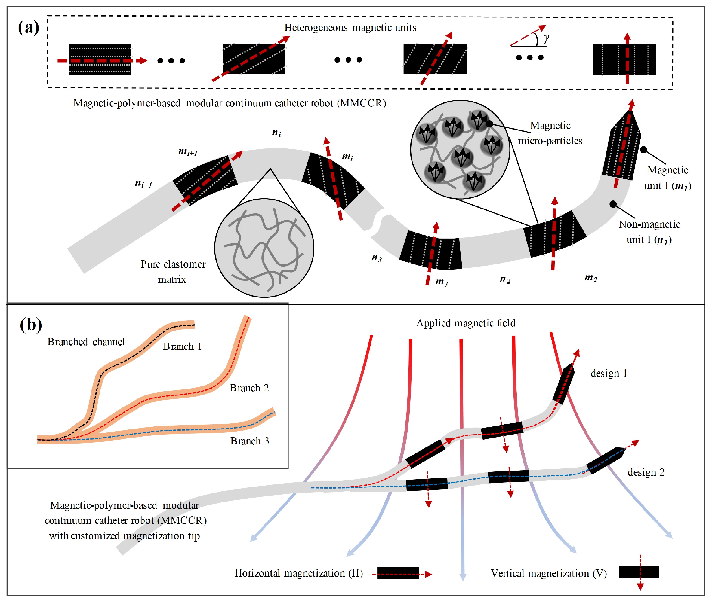
Abstract
:1. Introduction
2. Materials and Methods
2.1. MMCCR Design
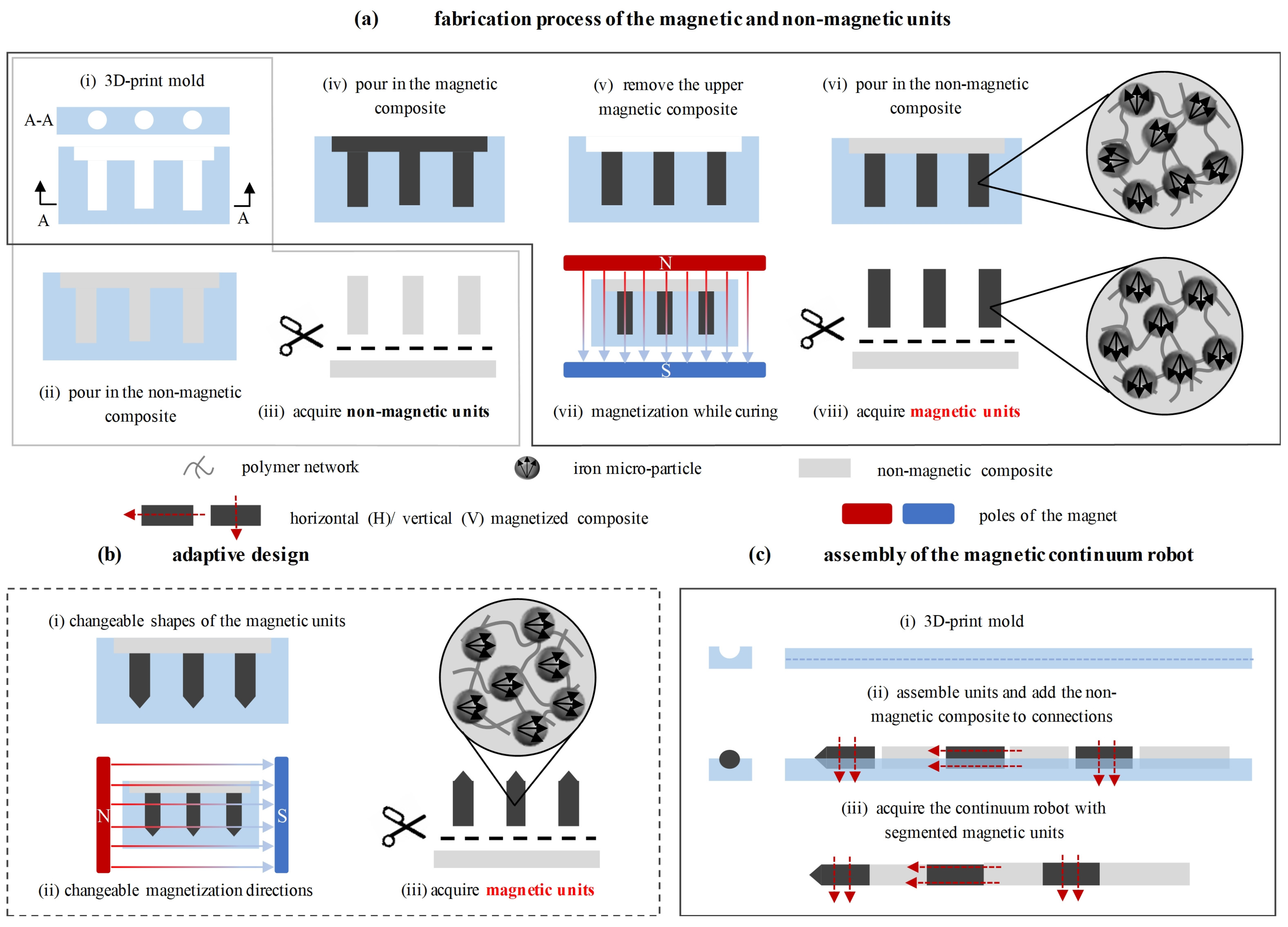
2.2. MMCCR Fabrication
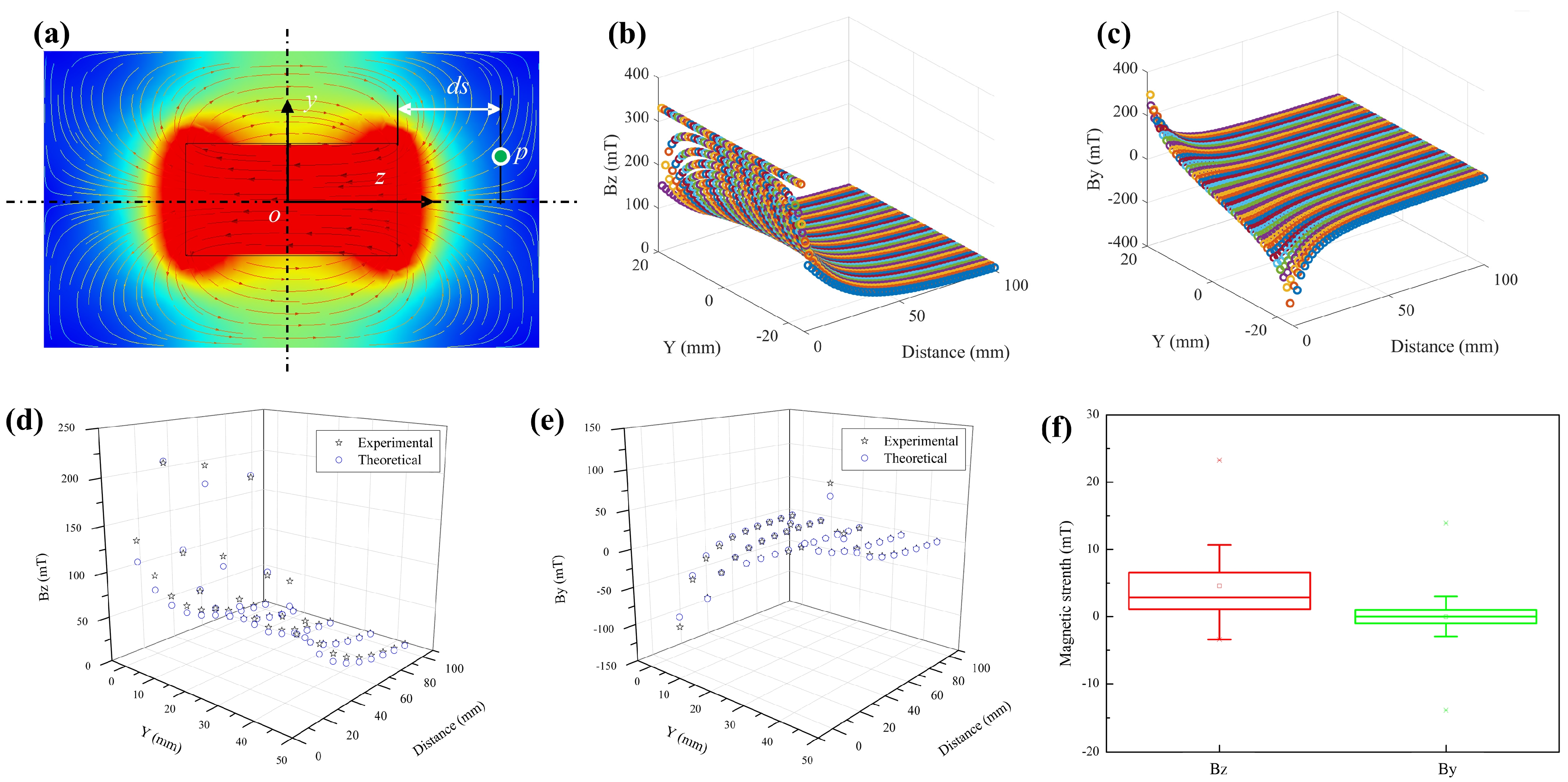
2.3. Characterization of the Applied Magnetic Field
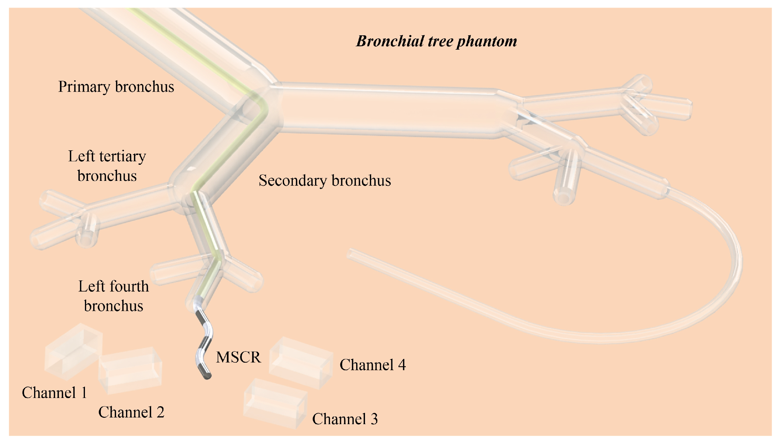
2.4. Test Model Preparation
3. Results
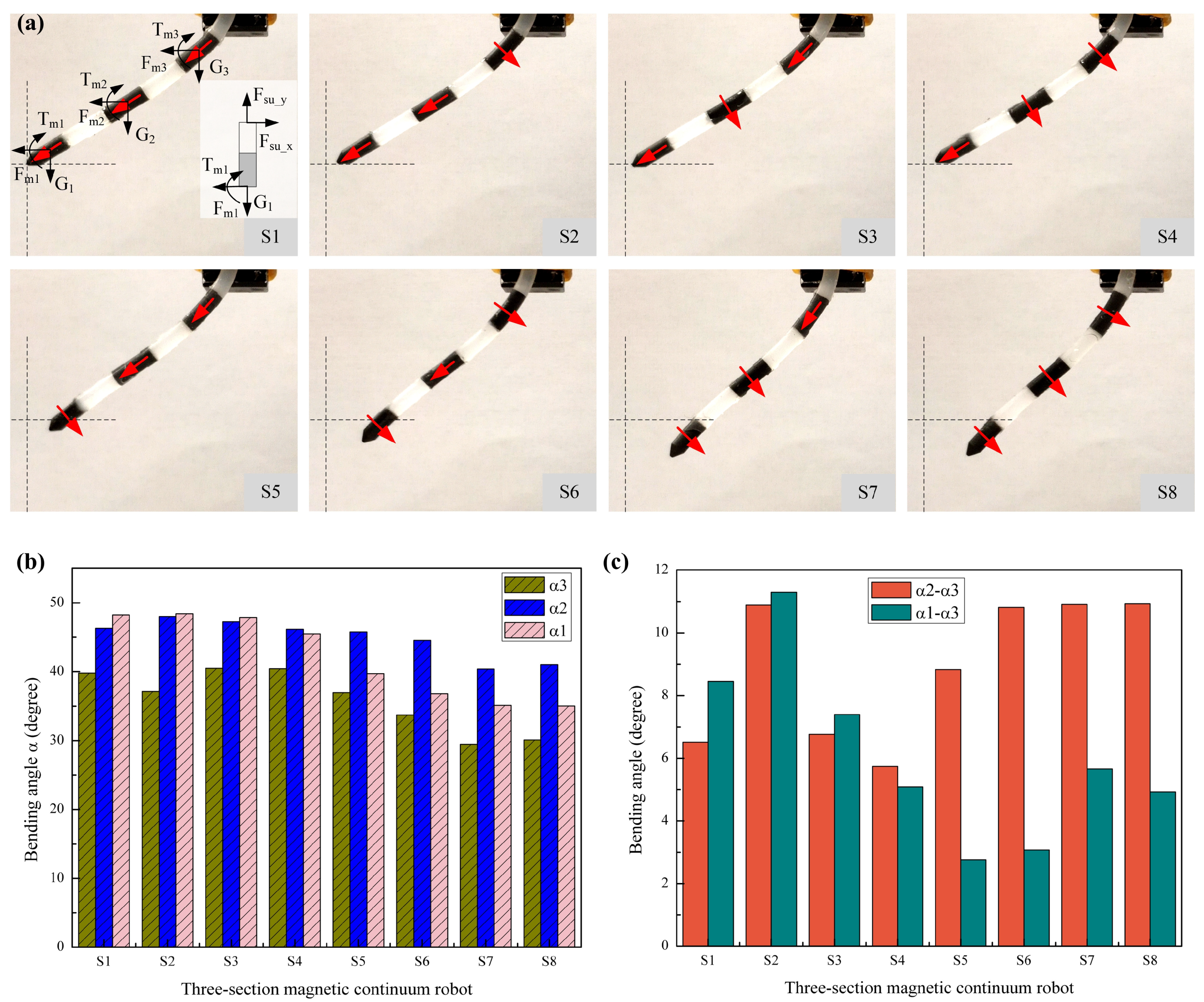
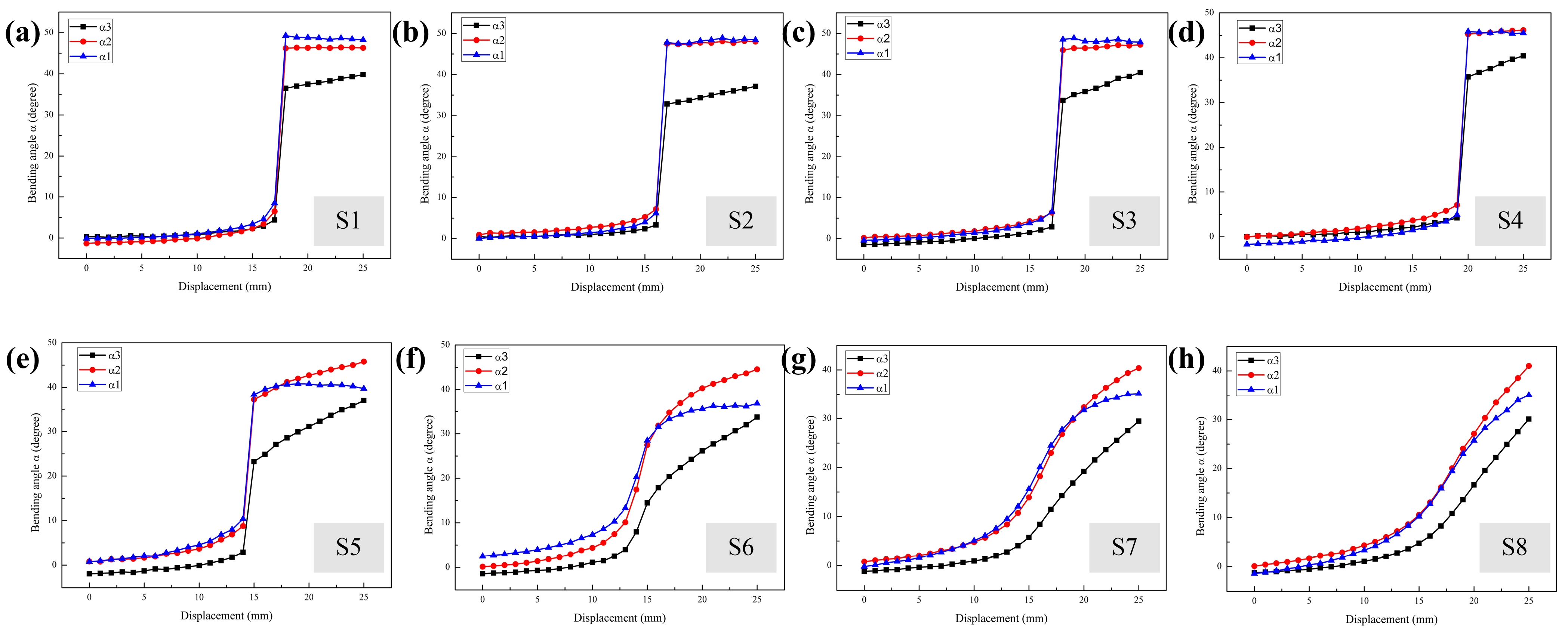
3.1. Static Bending Analysis of MMCCRs
3.2. Dynamic Deformation of MMCCRs
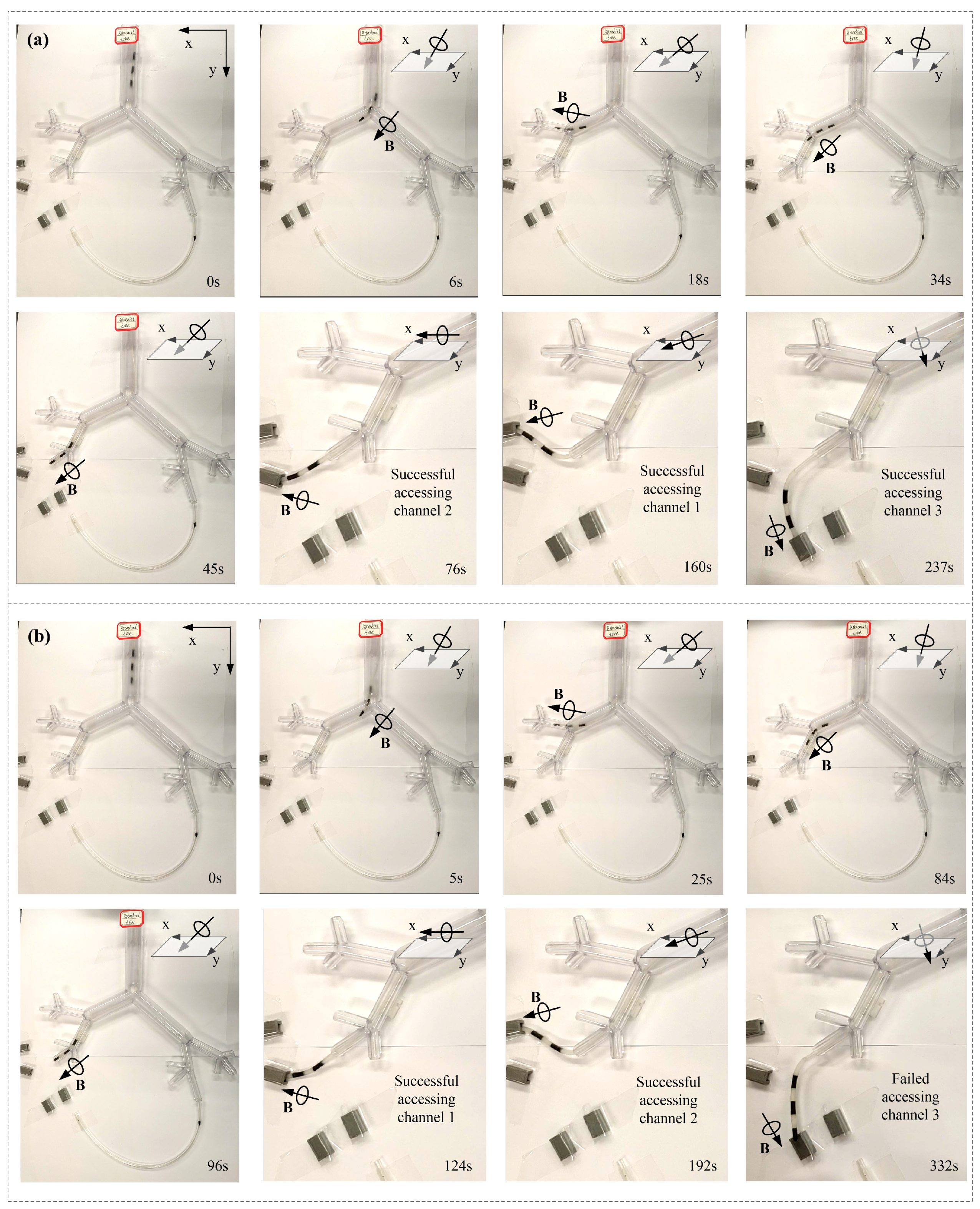
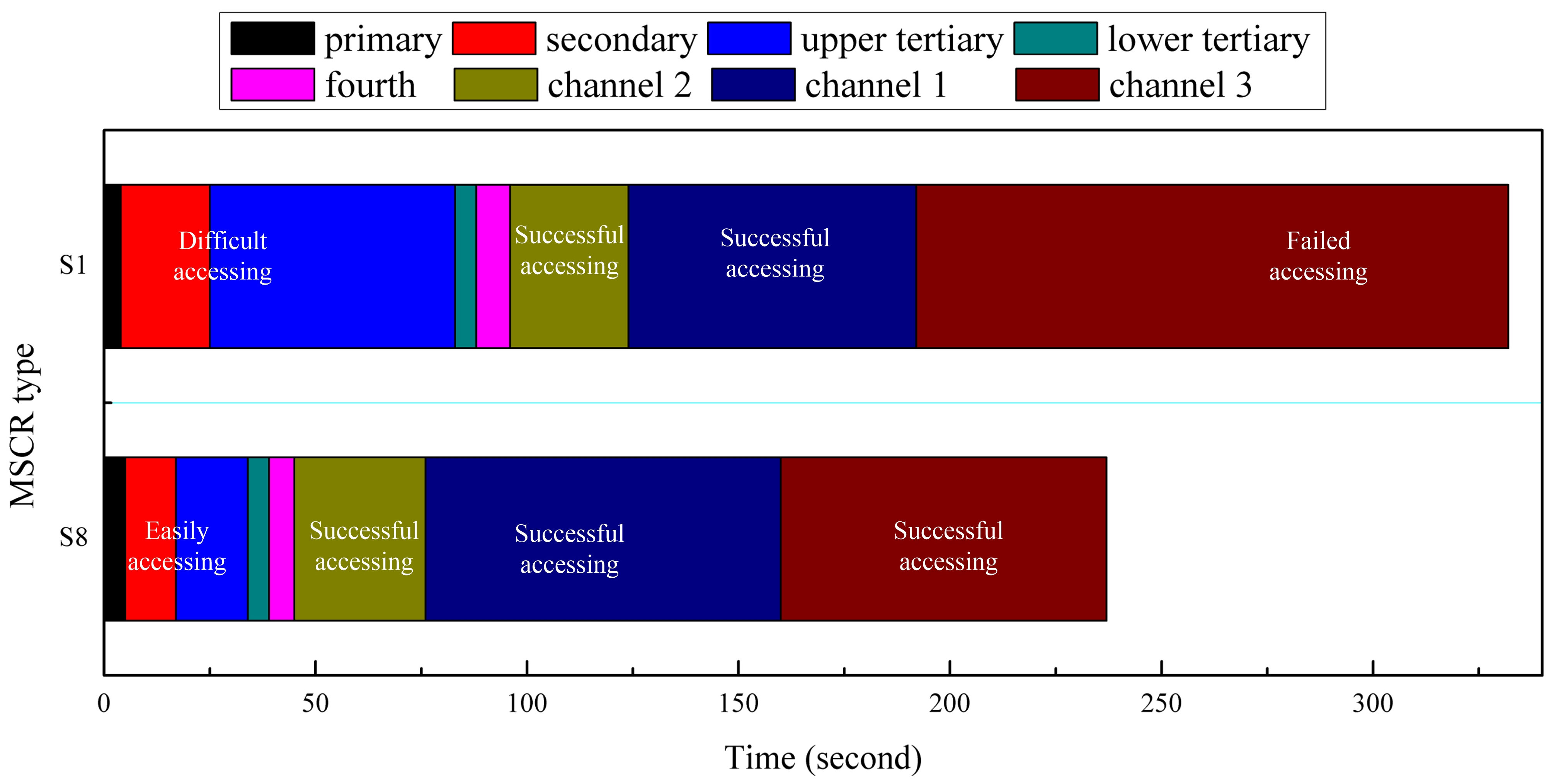
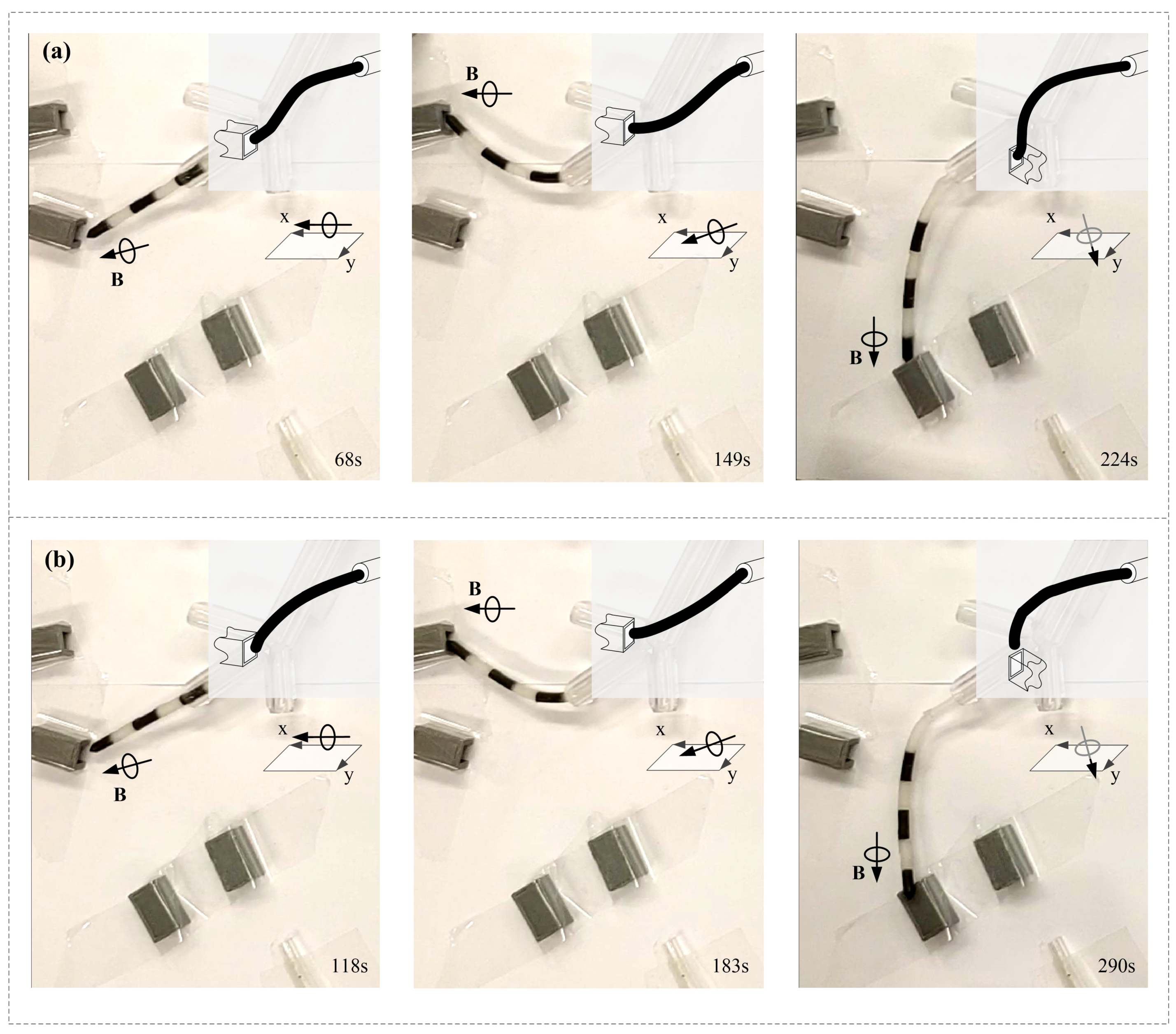
3.3. Adaptive Navigation of MMCCRs
4. Discussion
5. Conclusions
Supplementary Materials
Author Contributions
Funding
Data Availability Statement
Conflicts of Interest
References
- Kim, Y.; Zhao, X. Magnetic soft materials and robots. Chem. Rev. 2022, 122, 5317–5364. [Google Scholar] [CrossRef] [PubMed]
- Wang, B.; Kostarelos, K.; Nelson, B.J.; Zhang, L. Trends in micro-/nanorobotics: Materials development, actuation, localization, and system integration for biomedical applications. Adv. Mater. 2021, 33, 2002047. [Google Scholar] [CrossRef]
- Wu, S.; Hu, W.; Ze, Q.; Sitti, M.; Zhao, R. Multifunctional magnetic soft composites: A review. Multifunct. Mater. 2020, 3, 042003. [Google Scholar] [CrossRef] [PubMed]
- Zhang, J. Evolving from laboratory toys towards life-savers: Small-scale magnetic robotic systems with medical imaging modalities. Micromachines 2021, 12, 1310. [Google Scholar] [CrossRef] [PubMed]
- Xu, T.; Zhang, J.; Salehizadeh, M.; Onaizah, O.; Diller, E. Millimeter-scale flexible robots with programmable three-dimensional magnetization and motions. Sci. Robot. 2019, 4, eaav4494. [Google Scholar] [CrossRef]
- Li, G.; Zhang, T.; Shen, Y. Transparent Magnetic Soft Millirobot Actuated by Micro-Node Array. Adv. Mater. Technol. 2021, 6, 2100131. [Google Scholar] [CrossRef]
- Nelson, B.J.; Kaliakatsos, I.K.; Abbott, J.J. Microrobots for minimally invasive medicine. Annu. Rev. Biomed. Eng. 2010, 12, 55–85. [Google Scholar] [CrossRef]
- Sitti, M.; Ceylan, H.; Hu, W.; Giltinan, J.; Turan, M.; Yim, S.; Diller, E. Biomedical applications of untethered mobile milli/microrobots. Proc. IEEE 2015, 103, 205–224. [Google Scholar] [CrossRef]
- Hu, W.; Lum, G.Z.; Mastrangeli, M.; Sitti, M. Small-scale soft-bodied robot with multimodal locomotion. Nature 2018, 554, 81–85. [Google Scholar] [CrossRef]
- Gwisai, T.; Mirkhani, N.; Christiansen, M.G.; Nguyen, T.T.; Ling, V.; Schuerle, S. Magnetic torque–driven living microrobots for increased tumor infiltration. Sci. Robot. 2022, 7, eabo0665. [Google Scholar] [CrossRef]
- Tan, R.; Yang, X.; Lu, H.; Yang, L.; Zhang, T.; Miao, J.; Feng, Y.; Shen, Y. Nanofiber-based biodegradable millirobot with controllable anchoring and adaptive stepwise release functions. Matter 2022, 5, 1277–1295. [Google Scholar] [CrossRef]
- Dong, Y.; Wang, L.; Zhang, Z.; Ji, F.; Chan, T.K.F.; Yang, H.; Chan, C.P.L.; Yang, Z.; Chen, Z.; Chang, W.T.; et al. Endoscope-assisted magnetic helical micromachine delivery for biofilm eradication in tympanostomy tube. Sci. Adv. 2022, 8, eabq8573. [Google Scholar] [CrossRef] [PubMed]
- Yang, X.; Shang, W.; Lu, H.; Liu, Y.; Yang, L.; Tan, R.; Wu, X.; Shen, Y. An agglutinate magnetic spray transforms inanimate objects into millirobots for biomedical applications. Sci. Robot. 2020, 5, eabc8191. [Google Scholar] [CrossRef] [PubMed]
- Yang, X.; Tan, R.; Lu, H.; Fukuda, T.; Shen, Y. Milli-scale cellular robots that can reconfigure morphologies and behaviors simultaneously. Nat. Commun. 2022, 13, 4156. [Google Scholar] [CrossRef]
- Yang, L.; Zhang, T.; Tan, R.; Yang, X.; Guo, D.; Feng, Y.; Ren, H.; Tang, Y.; Shang, W.; Shen, Y. Functionalized Spiral-Rolling Millirobot for Upstream Swimming in Blood Vessel. Adv. Sci. 2022, 9, 2200342. [Google Scholar] [CrossRef] [PubMed]
- Edelmann, J.; Petruska, A.J.; Nelson, B.J. Magnetic control of continuum devices. Int. J. Robot. Res. 2017, 36, 68–85. [Google Scholar] [CrossRef]
- Jeon, S.; Hoshiar, A.K.; Kim, K.; Lee, S.; Kim, E.; Lee, S.; Kim, J.; Nelson, B.J.; Cha, H.-J.; Yi, B.-J.; et al. A magnetically controlled soft microrobot steering a guidewire in a three-dimensional phantom vascular network. Soft Robot. 2019, 6, 54–68. [Google Scholar] [CrossRef] [PubMed]
- Liu, D.; Liu, X.; Chen, Z.; Zuo, Z.; Tang, X.; Huang, Q.; Arai, T. Magnetically driven soft continuum microrobot for intravascular operations in microscale. Cyborg Bionic Syst. 2022, 2022, 9850832. [Google Scholar] [CrossRef]
- Kim, Y.; Parada, G.A.; Liu, S.; Zhao, X. Ferromagnetic soft continuum robots. Sci. Robot. 2019, 4, eaax7329. [Google Scholar] [CrossRef]
- Kim, Y.; Genevriere, E.; Harker, P.; Choe, J.; Balicki, M.; Regenhardt, R.W.; Vranic, J.E.; Dmytriw, A.A.; Patel, A.B.; Zhao, X. Telerobotic neurovascular interventions with magnetic manipulation. Sci. Robot. 2022, 7, eabg9907. [Google Scholar] [CrossRef]
- Zhang, T.; Yang, L.; Yang, X.; Tan, R.; Lu, H.; Shen, Y. Millimeter-scale soft continuum robots for large-angle and high-precision manipulation by hybrid actuation. Adv. Intell. Syst. 2021, 3, 2000189. [Google Scholar] [CrossRef] [PubMed]
- Lussi, J.; Gervasoni, S.; Mattille, M.; Dreyfus, R.; Boehler, Q.; Reinehr, M.; Ochsenbein, N.; Nelson, B.J.; Moehrlen, U. Magnetically Guided Laser Surgery for the Treatment of Twin-to-Twin Transfusion Syndrome. Adv. Intell. Syst. 2022, 4, 2200182. [Google Scholar] [CrossRef]
- Zhang, J.; Fang, Q.; Xiang, P.; Sun, D.; Xue, Y.; Jin, R.; Qiu, K.; Xiong, R.; Wang, Y.; Lu, H. A survey on design, actuation, modeling, and control of continuum robot. Cyborg Bionic Syst. 2022, 2022, 9754697. [Google Scholar] [CrossRef]
- Camarillo, D.B.; Milne, C.F.; Carlson, C.R.; Zinn, M.R.; Salisbury, J.K. Mechanics modeling of tendon-driven continuum manipulators. IEEE Trans. Robot. 2008, 24, 1262–1273. [Google Scholar] [CrossRef]
- Kato, T.; Okumura, I.; Song, S.E.; Golby, A.J.; Hata, N. Tendon-driven continuum robot for endoscopic surgery: Preclinical development and validation of a tension propagation model. IEEE/ASME Trans. Mechatron. 2014, 20, 2252–2263. [Google Scholar] [CrossRef]
- Kato, T.; Okumura, I.; Kose, H.; Takagi, K.; Hata, N. Tendon-driven continuum robot for neuroendoscopy: Validation of extended kinematic mapping for hysteresis operation. Int. J. Comput. Assist. Radiol. Surg. 2016, 11, 589–602. [Google Scholar] [CrossRef]
- Sander, I.L.; Dvorak, N.; Stebbins, J.A.; Carr, A.J.; Mouthuy, P.A. Advanced Robotics to Address the Translational Gap in Tendon Engineering. Cyborg Bionic Syst. 2022, 2022, 9842169. [Google Scholar] [CrossRef]
- Marchese, A.D.; Rus, D. Design, kinematics, and control of a soft spatial fluidic elastomer manipulator. Int. J. Robot. Res. 2016, 35, 840–869. [Google Scholar] [CrossRef]
- Mosadegh, B.; Polygerinos, P.; Keplinger, C.; Wennstedt, S.; Shepherd, R.F.; Gupta, U.; Shim, J.; Bertoldi, K.; Walsh, C.J.; Whitesides, G.M. Pneumatic networks for soft robotics that actuate rapidly. Adv. Funct. Mater. 2014, 24, 2163–2170. [Google Scholar] [CrossRef]
- Miao, J.; Zhang, T.; Li, G.; Guo, D.; Sun, S.; Tan, R.; Shi, J.; Shen, Y. Flagellar/Ciliary Intrinsic Driven Mechanism Inspired All-in-One Tubular Robotic Actuator. Engineering 2023, 1–11. [Google Scholar] [CrossRef]
- Gul, J.Z.; Yang, Y.J.; Su, K.Y.; Choi, K.H. Omni directional multimaterial soft cylindrical actuator and its application as a steerable catheter. Soft Robot. 2017, 4, 224–240. [Google Scholar] [CrossRef] [PubMed]
- Yang, C.; Geng, S.; Walker, I.; Branson, D.T.; Liu, J.; Dai, J.S.; Kang, R. Geometric constraint-based modeling and analysis of a novel continuum robot with Shape Memory Alloy initiated variable stiffness. Int. J. Robot. Res. 2020, 39, 1620–1634. [Google Scholar] [CrossRef]
- Kafash Hoshiar, A.; Jeon, S.; Kim, K.; Lee, S.; Kim, J.Y.; Choi, H. Steering algorithm for a flexible microrobot to enhance guidewire control in a coronary angioplasty application. Micromachines 2018, 9, 617. [Google Scholar] [CrossRef]
- Lin, D.; Wang, J.; Jiao, N.; Wang, Z.; Liu, L. A flexible magnetically controlled continuum robot steering in the enlarged effective workspace with constraints for retrograde intrarenal surgery. Adv. Intell. Syst. 2021, 3, 2000211. [Google Scholar] [CrossRef]
- Lin, D.; Li, N.; Jiao, N.; Wang, Z.; Liu, L. Kinematic Analysis of Multi-Section Opposite Magnetic Catheter Robots with Solution Multiplicity. IEEE Trans. Autom. Sci. Eng. 2022, 1–12. [Google Scholar] [CrossRef]
- Wang, L.; Guo, C.F.; Zhao, X. Magnetic soft continuum robots with contact forces. Extreme Mech. Lett. 2022, 51, 101604. [Google Scholar] [CrossRef]
- Wang, L.; Zheng, D.; Harker, P.; Patel, A.B.; Guo, C.F.; Zhao, X. Evolutionary design of magnetic soft continuum robots. Proc. Natl. Acad. Sci. USA 2021, 118, e2021922118. [Google Scholar] [CrossRef]
- Lin, D.; Jiao, N.; Wang, Z.; Liu, L. A magnetic continuum robot with multi-mode control using opposite-magnetized magnets. IEEE Robot. Autom. Lett. 2021, 6, 2485–2492. [Google Scholar] [CrossRef]
- Lum, G.Z.; Ye, Z.; Dong, X.; Marvi, H.; Erin, O.; Hu, W.; Sitti, M. Shape-programmable magnetic soft matter. Proc. Natl. Acad. Sci. USA 2016, 113, E6007–E6015. [Google Scholar] [CrossRef]
- Alapan, Y.; Karacakol, A.C.; Guzelhan, S.N.; Isik, I.; Sitti, M. Reprogrammable shape morphing of magnetic soft machines. Sci. Adv. 2020, 6, eabc6414. [Google Scholar] [CrossRef]
- Gou, X.; Yang, Y.; Zheng, X. Analytic expression of magnetic field distribution of rectangular permanent magnets. Appl. Math. Mech. 2004, 25, 297–306. [Google Scholar]


Disclaimer/Publisher’s Note: The statements, opinions and data contained in all publications are solely those of the individual author(s) and contributor(s) and not of MDPI and/or the editor(s). MDPI and/or the editor(s) disclaim responsibility for any injury to people or property resulting from any ideas, methods, instructions or products referred to in the content. |
© 2023 by the authors. Licensee MDPI, Basel, Switzerland. This article is an open access article distributed under the terms and conditions of the Creative Commons Attribution (CC BY) license (https://creativecommons.org/licenses/by/4.0/).
Share and Cite
Zhang, T.; Li, G.; Yang, X.; Ren, H.; Guo, D.; Wang, H.; Chan, K.; Ye, Z.; Zhao, T.; Zhang, C.; et al. A Fast Soft Continuum Catheter Robot Manufacturing Strategy Based on Heterogeneous Modular Magnetic Units. Micromachines 2023, 14, 911. https://doi.org/10.3390/mi14050911
Zhang T, Li G, Yang X, Ren H, Guo D, Wang H, Chan K, Ye Z, Zhao T, Zhang C, et al. A Fast Soft Continuum Catheter Robot Manufacturing Strategy Based on Heterogeneous Modular Magnetic Units. Micromachines. 2023; 14(5):911. https://doi.org/10.3390/mi14050911
Chicago/Turabian StyleZhang, Tieshan, Gen Li, Xiong Yang, Hao Ren, Dong Guo, Hong Wang, Ki Chan, Zhou Ye, Tianshuo Zhao, Chengfei Zhang, and et al. 2023. "A Fast Soft Continuum Catheter Robot Manufacturing Strategy Based on Heterogeneous Modular Magnetic Units" Micromachines 14, no. 5: 911. https://doi.org/10.3390/mi14050911