
Design of Hybrid Beamforming System Based on Practical Circuit Parameter of 6-Bit Millimeter-Wave Phase Shifters


Abstract
:1. Introduction
2. Phase Shifter Circuit and Hybrid Beamforming Design
3. Results and Discussions
4. Conclusions
Author Contributions
Funding
Data Availability Statement
Conflicts of Interest
References
- Feng, W.; Li, Y.; Jin, D.; Su, L.; Chen, S. Millimetre-wave backhaul for 5G networks: Challenges and solutions. Sensors 2016, 16, 892. [Google Scholar] [CrossRef] [PubMed]
- Hemadeh, I.A.; Satyanarayana, K.; El-Hajjar, M.; Hanzo, L. Millimeter-Wave Communications: Physical Channel Models, Design Considerations, Antenna Constructions, and Link-Budget. IEEE Commun. Surv. Tutor. 2018, 20, 870–913. [Google Scholar] [CrossRef]
- Berlo, B.v.; Elkelany, A.; Ozcelebi, T.; Meratnia, N. Millimeter Wave Sensing: A Review of Application Pipelines and Building Blocks. IEEE Sens. J. 2021, 21, 10332–10368. [Google Scholar] [CrossRef]
- Al-Saman, A.; Cheffena, M.; Elijah, O.; Al-Gumaei, Y.A.; Abdul Rahim, S.K.; Al-Hadhrami, T. Survey of millimeter-wave propagation measurements and models in indoor environments. Electronics 2021, 10, 1653. [Google Scholar] [CrossRef]
- He, R.; Ai, B.; Stüber, G.L.; Wang, G.; Zhong, Z. Geometrical-based modeling for millimeter-wave MIMO mobile-to-mobile channels. IEEE Trans. Veh. Technol. 2017, 67, 2848–2863. [Google Scholar] [CrossRef]
- Wu, S.; Wang, C.-X.; Alwakeel, M.M.; You, X. A general 3-D non-stationary 5G wireless channel model. IEEE Trans. Commun. 2017, 66, 3065–3078. [Google Scholar] [CrossRef]
- Chen, X.; Abdullah, M.; Li, Q.; Li, J.; Zhang, A.; Svensson, T. Characterizations of mutual coupling effects on switch-based phased array antennas for 5G millimeter-wave mobile communications. IEEE Access 2019, 7, 31376–31384. [Google Scholar] [CrossRef]
- Hefnawi, M. Hybrid beamforming for millimeter-wave heterogeneous networks. Electronics 2019, 8, 133. [Google Scholar] [CrossRef]
- Lialios, D.I.; Ntetsikas, N.; Paschaloudis, K.D.; Zekios, C.L.; Georgakopoulos, S.V.; Kyriacou, G.A. Design of true time delay millimeter wave beamformers for 5G multibeam phased arrays. Electronics 2020, 9, 1331. [Google Scholar] [CrossRef]
- Liu, G.; Deng, H.; Yang, K.; Zhu, Z.; Liu, J.; Dong, H. A New Design of Codebook for Hybrid Precoding in Millimeter-Wave Massive MIMO Systems. Symmetry 2021, 13, 743. [Google Scholar] [CrossRef]
- Dahrouj, H.; Yu, W. Coordinated beamforming for the multicell multi-antenna wireless system. IEEE Trans. Wirel. Commun. 2010, 9, 1748–1759. [Google Scholar] [CrossRef]
- Rappaport, T.S.; Sun, S.; Mayzus, R.; Zhao, H.; Azar, Y.; Wang, K.; Wong, G.N.; Schulz, J.K.; Samimi, M.; Gutierrez, F. Millimeter wave mobile communications for 5G cellular: It will work! IEEE Access 2013, 1, 335–349. [Google Scholar] [CrossRef]
- Kinol, A.; Nisha, A.; Marshiana, D.; Krishnamoorthy, N. Hybrid Multi Beamforming and Multi-User Detection Technique for MU MIMO System. Wirel. Pers. Commun. 2022, 124, 3375–3385. [Google Scholar] [CrossRef]
- Kononchuk, R.; Suwunnarat, S.; Hilario, M.S.; Baros, A.E.; Hoff, B.W.; Vasilyev, V.; Vitebskiy, I.; Kottos, T.; Chabanov, A.A. A reflective millimeter-wave photonic limiter. Sci. Adv. 2022, 8, eabh1827. [Google Scholar] [CrossRef]
- Ahmed, I.; Khammari, H.; Shahid, A.; Musa, A.; Kim, K.S.; De Poorter, E.; Moerman, I. A survey on hybrid beamforming techniques in 5G: Architecture and system model perspectives. IEEE Commun. Surv. Tutor. 2018, 20, 3060–3097. [Google Scholar] [CrossRef]
- Chen, Y.; Wen, X.; Lu, Z. Achievable spectral efficiency of hybrid beamforming massive MIMO systems with quantized phase shifters, channel non-reciprocity and estimation errors. IEEE Access 2020, 8, 71304–71317. [Google Scholar] [CrossRef]
- Zhang, J.; Yu, X.; Letaief, K.B. Hybrid beamforming for 5G and beyond millimeter-wave systems: A holistic view. IEEE Open J. Commun. Soc. 2019, 1, 77–91. [Google Scholar] [CrossRef]
- Kim, D.-C.; Chi, Y.-E.; Park, J.; Minz, L.; Park, S.-O. High Resolution Digital Beamforming Receiver Using DDS-PLL Signal Generator for 5G Mobile Communication. IEEE Trans. Antennas Propag. 2021, 70, 1428–1439. [Google Scholar] [CrossRef]
- Zheng, B.; Jie, L.; Flynn, M.P. A 6-GHz MU-MIMO Eight-Element Direct Digital Beamforming TX Utilizing FIR H-Bridge DAC. IEEE Trans. Microw. Theory Tech. 2021, 69, 2832–2840. [Google Scholar] [CrossRef]
- Rangan, S.; Rappaport, T.S.; Erkip, E. Millimeter-wave cellular wireless networks: Potentials and challenges. Proc. IEEE 2014, 102, 366–385. [Google Scholar] [CrossRef]
- Hansen, C.J. WiGiG: Multi-gigabit wireless communications in the 60 GHz band. IEEE Wirel. Commun. 2011, 18, 6–7. [Google Scholar] [CrossRef]
- Raviteja, P.; Hong, Y.; Viterbo, E. Millimeter Wave Analog Beamforming With Low Resolution Phase Shifters for Multiuser Uplink. IEEE Trans. Veh. Technol. 2018, 67, 3205–3215. [Google Scholar] [CrossRef]
- Alkhateeb, A.; Mo, J.; Gonzalez-Prelcic, N.; Heath, R.W. MIMO precoding and combining solutions for millimeter-wave systems. IEEE Commun. Mag. 2014, 52, 122–131. [Google Scholar] [CrossRef]
- Zhang, J.A.; Huang, X.; Dyadyuk, V.; Guo, Y.J. Massive hybrid antenna array for millimeter-wave cellular communications. IEEE Wirel. Commun. 2015, 22, 79–87. [Google Scholar] [CrossRef]
- Bogale, T.E.; Le, L.B.; Haghighat, A.; Vandendorpe, L. On the number of RF chains and phase shifters, and scheduling design with hybrid analog–digital beamforming. IEEE Trans. Wirel. Commun. 2016, 15, 3311–3326. [Google Scholar] [CrossRef]
- Sohrabi, F.; Yu, W. Hybrid digital and analog beamforming design for large-scale antenna arrays. IEEE J. Sel. Top. Signal Process. 2016, 10, 501–513. [Google Scholar] [CrossRef]
- Wang, W.; Yin, H.; Chen, X.; Wang, W. Robust and low-overhead hybrid beamforming design with imperfect phase shifters in multi-user millimeter wave systems. IEEE Access 2020, 8, 74002–74014. [Google Scholar] [CrossRef]
- Wan, S.; Zhu, H.; Kang, K.; Qian, H. On the Performance of Fully-Connected and Sub-Connected Hybrid Beamforming System. IEEE Trans. Veh. Technol. 2021, 70, 11078–11082. [Google Scholar] [CrossRef]
- Abdulkawi, W.M.; Alqaisei, M.A.; Sheta, A.-F.A.; Elshafiey, I. New Compact Antenna Array for MIMO Internet of Things Applications. Micromachines 2022, 13, 1481. [Google Scholar] [CrossRef]
- El Ayach, O.; Rajagopal, S.; Abu-Surra, S.; Pi, Z.; Heath, R.W. Spatially sparse precoding in millimeter wave MIMO systems. IEEE Trans. Wirel. Commun. 2014, 13, 1499–1513. [Google Scholar] [CrossRef]
- Du, J.; Xu, W.; Zhao, C.; Vandendorpe, L. Hybrid beamforming design for multiuser massive MIMO-OFDM systems. In Proceedings of the 2018 15th International Symposium on Wireless Communication Systems (ISWCS), Lisbon, Portugal, 28–31 August 2018; pp. 1–6. [Google Scholar]
- Yuan, H.; Yang, N.; Yang, K.; Han, C.; An, J. Hybrid beamforming for terahertz multi-carrier systems over frequency selective fading. IEEE Trans. Commun. 2020, 68, 6186–6199. [Google Scholar] [CrossRef]
- Magueta, R.; Teodoro, S.; Castanheira, D.; Silva, A.; Dinis, R.; Gameiro, A. Multiuser equalizer for hybrid massive MIMO mmWave CE-OFDM systems. Appl. Sci. 2019, 9, 3363. [Google Scholar] [CrossRef]
- Alkhateeb, A.; Heath, R.W. Frequency selective hybrid precoding for limited feedback millimeter wave systems. IEEE Trans. Commun. 2016, 64, 1801–1818. [Google Scholar] [CrossRef]
- Yu, X.; Shen, J.-C.; Zhang, J.; Letaief, K.B. Alternating minimization algorithms for hybrid precoding in millimeter wave MIMO systems. IEEE J. Sel. Top. Signal Process. 2016, 10, 485–500. [Google Scholar] [CrossRef]
- Cheng, Z.; He, Z.; Liao, B. Hybrid Beamforming for Multi-Carrier Dual-Function Radar-Communication System. IEEE Trans. Cogn. Commun. Netw. 2021, 7, 1002–1015. [Google Scholar] [CrossRef]
- Ioushua, S.S.; Eldar, Y.C. Hybrid analog-digital beamforming for massive MIMO systems. arXiv 2017, arXiv:1712.03485. [Google Scholar]
- Gao, X.; Dai, L.; Sayeed, A.M. Low RF-complexity technologies to enable millimeter-wave MIMO with large antenna array for 5G wireless communications. IEEE Commun. Mag. 2018, 56, 211–217. [Google Scholar] [CrossRef]
- Nasir, A.A.; Tuan, H.D.; Duong, T.Q.; Poor, H.V.; Hanzo, L. Hybrid beamforming for multi-user millimeter-wave networks. IEEE Trans. Veh. Technol. 2020, 69, 2943–2956. [Google Scholar] [CrossRef]
- Fettweis, G.; Löhning, M.; Petrovic, D.; Windisch, M.; Zillmann, P.; Zimmermann, E. Dirty RF. In Proceedings of the Wireless World Research Forum (WWRF) Meeting; Available online: https://wwrf.ch/ (accessed on 4 January 2023).
- Fettweis, G.; Löhning, M.; Petrovic, D.; Windisch, M.; Zillmann, P.; Rave, W. Dirty RF: A new paradigm. Int. J. Wirel. Inf. Netw. 2007, 14, 133–148. [Google Scholar] [CrossRef]
- Ariaudo, M.; Fijalkow, I.; Gautier, J.-L.; Brandon, M.; Aziz, B.; Milevsky, B. Green radio despite “Dirty RF” front-end. EURASIP J. Wirel. Commun. Netw. 2012, 2012, 1–9. [Google Scholar] [CrossRef]
- Kodak, U.; Rebeiz, G.M. A 5G 28-GHz common-leg T/R front-end in 45-nm CMOS SOI with 3.7-dB NF and− 30-dBc EVM with 64-QAM/500-MBaud modulation. IEEE Trans. Microw. Theory Tech. 2018, 67, 318–331. [Google Scholar] [CrossRef]
- Gösele, U.; Tong, Q.-Y. Semiconductor wafer bonding. Annu. Rev. Mater. Sci. 1998, 28, 215–241. [Google Scholar] [CrossRef]
- Kononchuk, O.; Nguyen, B.-Y. Silicon-On-Insulator (SOI) Technology: Manufacture and Applications; Elsevier: Amsterdam, The Netherlands, 2014. [Google Scholar]
- Pu, M.; Liu, L.; Xue, W.; Ding, Y.; Frandsen, L.H.; Ou, H.; Yvind, K.; Hvam, J.M. Tunable microwave phase shifter based on silicon-on-insulator microring resonator. IEEE Photonics Technol. Lett. 2010, 22, 869–871. [Google Scholar] [CrossRef]
- Ehteshami, N.; Zhang, W.; Yao, J. Optically tunable full 360° microwave photonic phase shifter using three cascaded silicon-on-insulator microring resonators. Opt. Commun. 2016, 373, 53–58. [Google Scholar] [CrossRef]
- GlobalFoundries. Available online: www.globalfoundries.com (accessed on 4 January 2022).
- Li, S.; Nguyen, H.T.; Chi, T.; Li, C.; Cahoon, N.; Kumar, A.; Freeman, G.; Harame, D.; Wang, H. Performance of v-band on-chip antennas in globalfoundries 45nm CMOS SOI process for mm-wave 5G applications. In Proceedings of the 2018 IEEE/MTT-S International Microwave Symposium-IMS, Philadelphia, PA, USA, 10–15 June 2018; pp. 1593–1596. [Google Scholar]
- Dilli, R. Performance analysis of multi user massive MIMO hybrid beamforming systems at millimeter wave frequency bands. Wirel. Netw. 2021, 27, 1925–1939. [Google Scholar] [CrossRef]
- Alqaisei, M.A.; Sheta, A.-F.A.; Elshafiey, I. Hybrid Beamforming for Multi-User Massive MIMO Systems at Millimeter-Wave Networks. In Proceedings of the 2022 39th National Radio Science Conference (NRSC), Cairo, Egypt, 29 November–1 December 2022; pp. 181–187. [Google Scholar]
- El Ayach, O.; Heath, R.W.; Rajagopal, S.; Pi, Z. Multimode precoding in millimeter wave MIMO transmitters with multiple antenna sub-arrays. In Proceedings of the 2013 IEEE Global Communications Conference (GLOBECOM), Atlanta, GA, USA, 9–13 December 2013; pp. 3476–3480. [Google Scholar]
- Spencer, Q.H.; Swindlehurst, A.L.; Haardt, M. Zero-forcing methods for downlink spatial multiplexing in multiuser MIMO channels. IEEE Trans. Signal Process. 2004, 52, 461–471. [Google Scholar] [CrossRef]
- Uzunkol, M.; Rebeiz, G.M. A 65 GHz LNA/phase shifter with 4.3 dB NF using 45 nm CMOS SOI. IEEE Microw. Wirel. Compon. Lett. 2012, 22, 530–532. [Google Scholar] [CrossRef]
- Inac, O.; Uzunkol, M.; Rebeiz, G.M. 45-nm CMOS SOI technology characterization for millimeter-wave applications. IEEE Trans. Microw. Theory Tech. 2014, 62, 1301–1311. [Google Scholar] [CrossRef]
- Chiu, H.-C.; Chen, C.-M.; Chang, L.-C.; Kao, H.-L. A 5-Bit X-Band GaN HEMT-Based Phase Shifter. Electronics 2021, 10, 658. [Google Scholar] [CrossRef]
- Siegrist, K. Probability, Mathematical Statistics, Stochastic Processes; LibreTexts: Los Angeles, CA, USA, 2017. [Google Scholar]


| Phase Degrees | L1 (pH) | L2 (pH) | C1 (fF) | C2 (fF) |
|---|---|---|---|---|
| 180° | 284 | 384 | 125 | 80 |
| 90° | 223 | 157 | 500 | 5.5 |
| 45° | 6200 | 246 | 1680 | 38.8 |
| 22.5° | 1783 | 46.9 | 1227 | 40.8 |
| Distribution Type | RMS EVM for Actual Model of Phase Shifters | RMS EVM for Ideal Phase Shifters | Difference between Actual and Ideal |
|---|---|---|---|
| Exponential | −4877.62 | −4650.74 | ---------- |
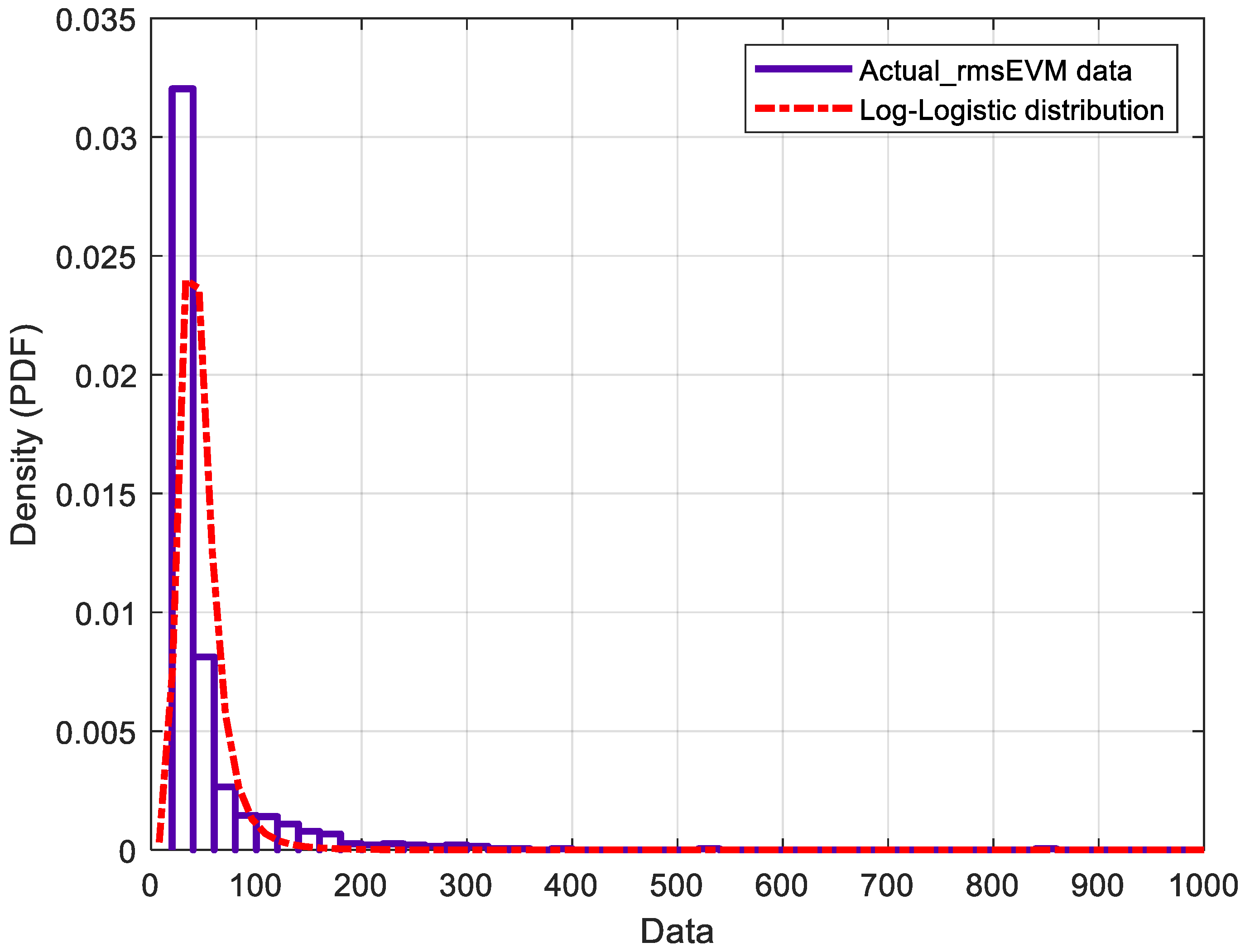
| Log-Logistic | −4317.32 | −2756.11 | ---------- |
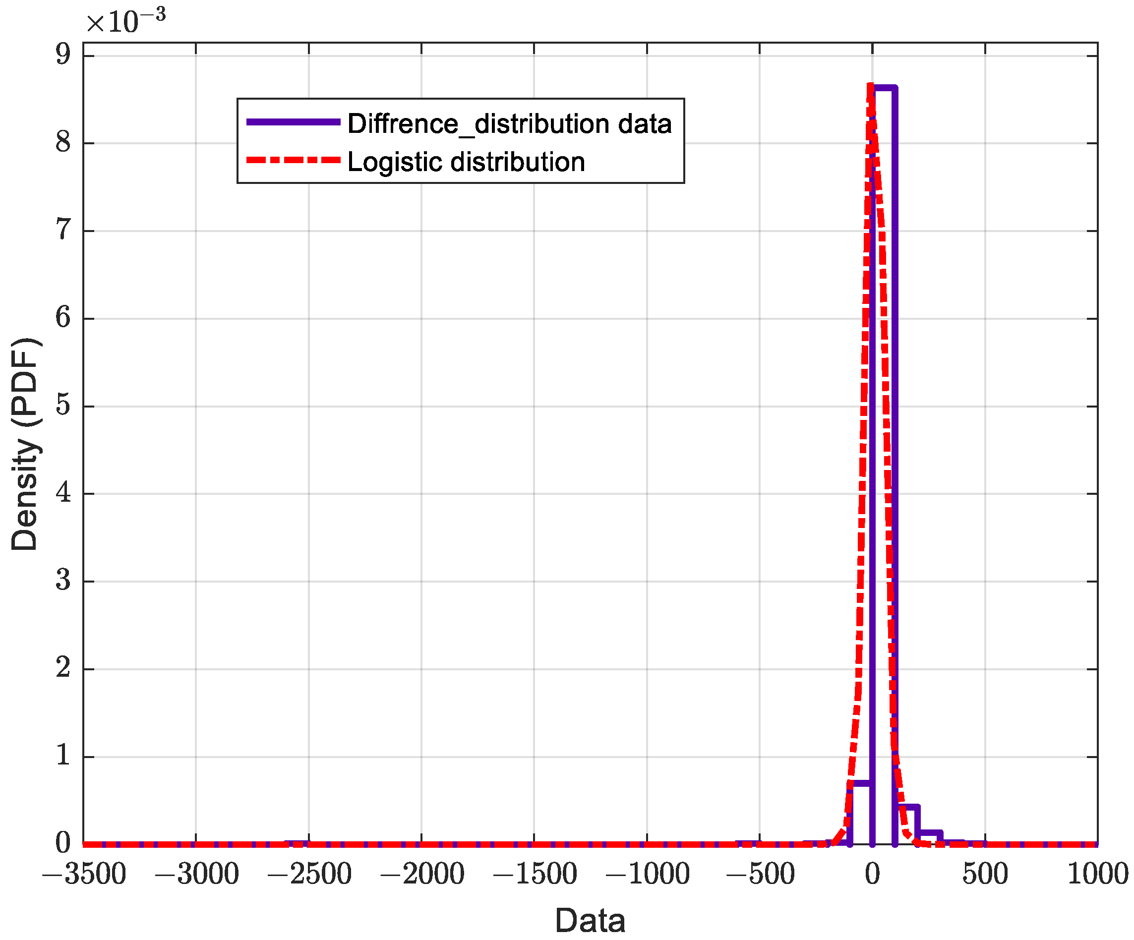
| Logistic | −4920.82 | −2344.26 | −5151.58 |
| Nakagami | −5011.59 | −5341.06 | ---------- |
| Normal | −5401.58 | −6232.33 | −6240.35 |
| Distribution Type | Log-Likelihood | Mean | Variance | Parameter Estimate Standard Error | ||||
|---|---|---|---|---|---|---|---|---|
| µ | µ Error | σ | σ-Error | |||||
| RMS EVM for Actual Model | Log-Logistic | −4317.32 | 46.997 | 481.359 | 3.7622 | 0.01226 | 0.2291 | 0.006769 |
| RMS EVM for Ideal Model | Logistic | −2756.11 | 36.4697 | 10.4387 | 3.5926 | 0.00235 | 0.04862 | 0.001503 |
| Difference between actual and ideal | Logistic | −5151.58 | 10.9149 | 1852.58 | 10.915 | 1.18592 | 23.7301 | 0.719523 |
Disclaimer/Publisher’s Note: The statements, opinions and data contained in all publications are solely those of the individual author(s) and contributor(s) and not of MDPI and/or the editor(s). MDPI and/or the editor(s) disclaim responsibility for any injury to people or property resulting from any ideas, methods, instructions or products referred to in the content. |
© 2023 by the authors. Licensee MDPI, Basel, Switzerland. This article is an open access article distributed under the terms and conditions of the Creative Commons Attribution (CC BY) license (https://creativecommons.org/licenses/by/4.0/).
Share and Cite
Alqaisei, M.A.; Sheta, A.-F.A.; Elshafiey, I.; Altamimi, M. Design of Hybrid Beamforming System Based on Practical Circuit Parameter of 6-Bit Millimeter-Wave Phase Shifters. Micromachines 2023, 14, 875. https://doi.org/10.3390/mi14040875
Alqaisei MA, Sheta A-FA, Elshafiey I, Altamimi M. Design of Hybrid Beamforming System Based on Practical Circuit Parameter of 6-Bit Millimeter-Wave Phase Shifters. Micromachines. 2023; 14(4):875. https://doi.org/10.3390/mi14040875
Chicago/Turabian StyleAlqaisei, Mohammed A., Abdel-Fattah A. Sheta, Ibrahim Elshafiey, and Majid Altamimi. 2023. "Design of Hybrid Beamforming System Based on Practical Circuit Parameter of 6-Bit Millimeter-Wave Phase Shifters" Micromachines 14, no. 4: 875. https://doi.org/10.3390/mi14040875