

Design and Analysis of Circular Polarized Two-Port MIMO Antennas with Various Antenna Element Orientations
 , , , , , and
Abstract
:1. Introduction
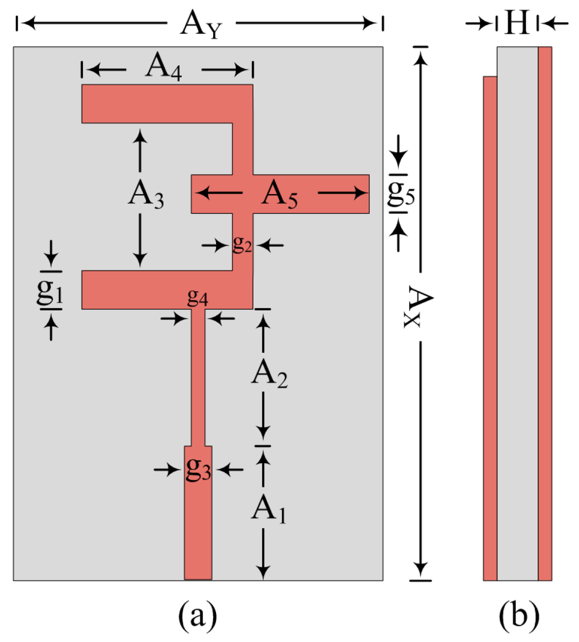
2. Design of Broadband CP Antenna
2.1. Antenna Design Approach
2.2. Paraneteric Analysis
2.2.1. Width of the Middle Stub (g5)
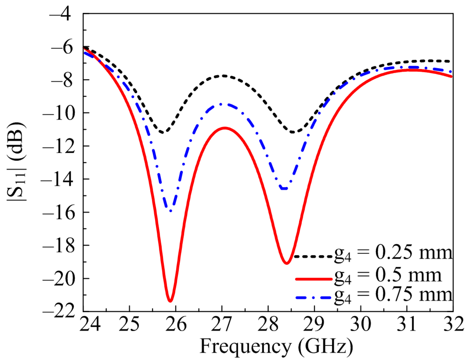
2.2.2. Width of the Extended Feedline (g4)
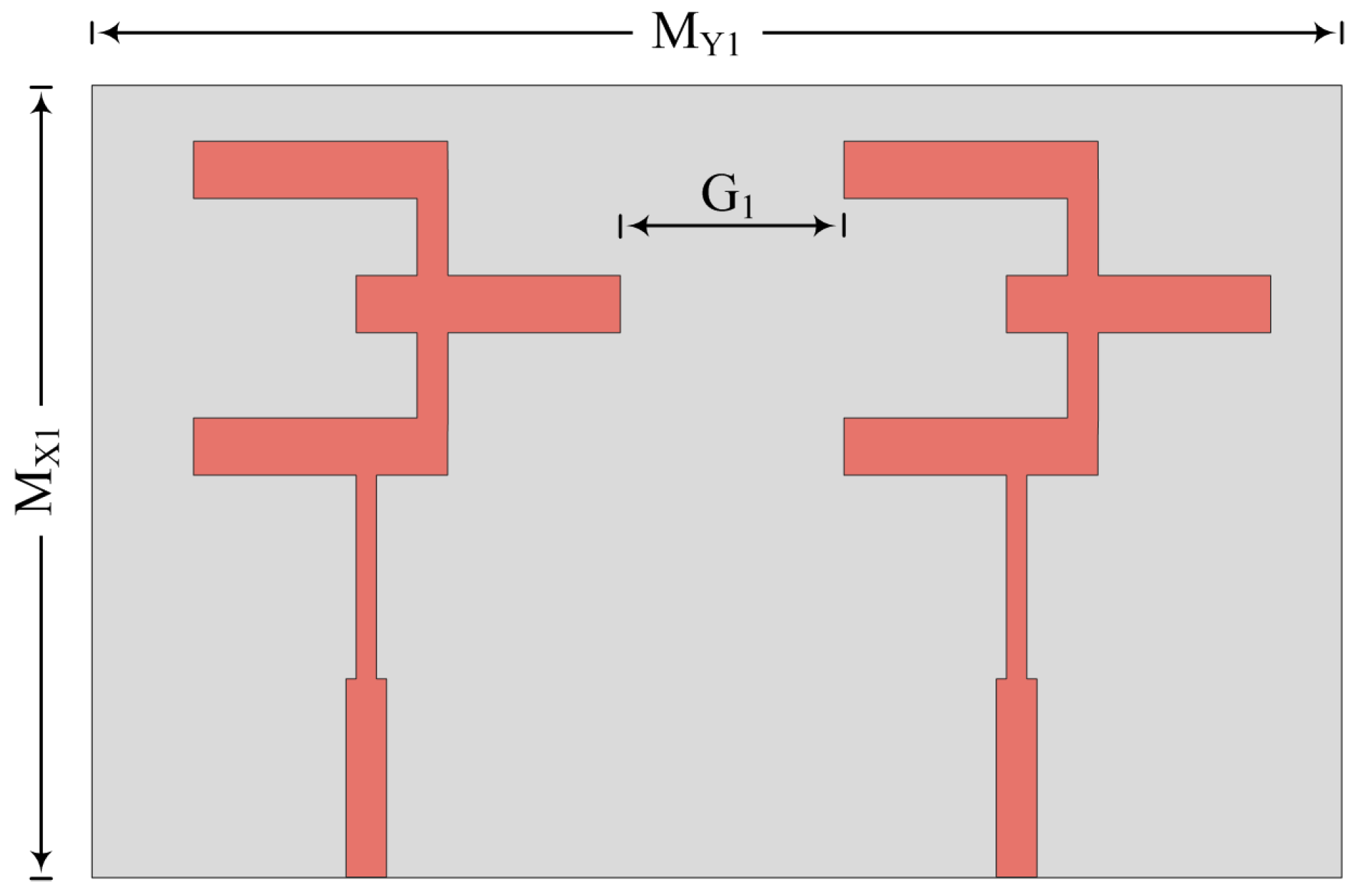
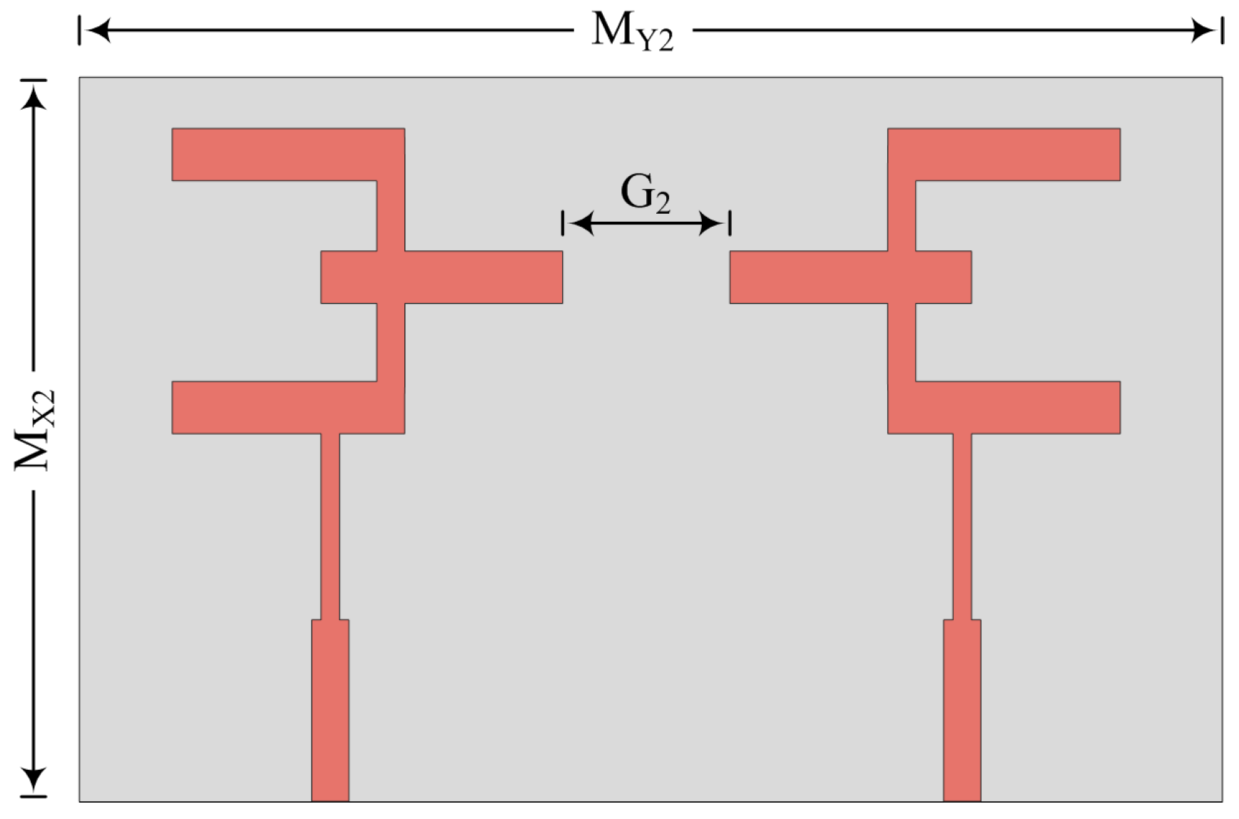
3. MIMO Antenna Configuration Analysis
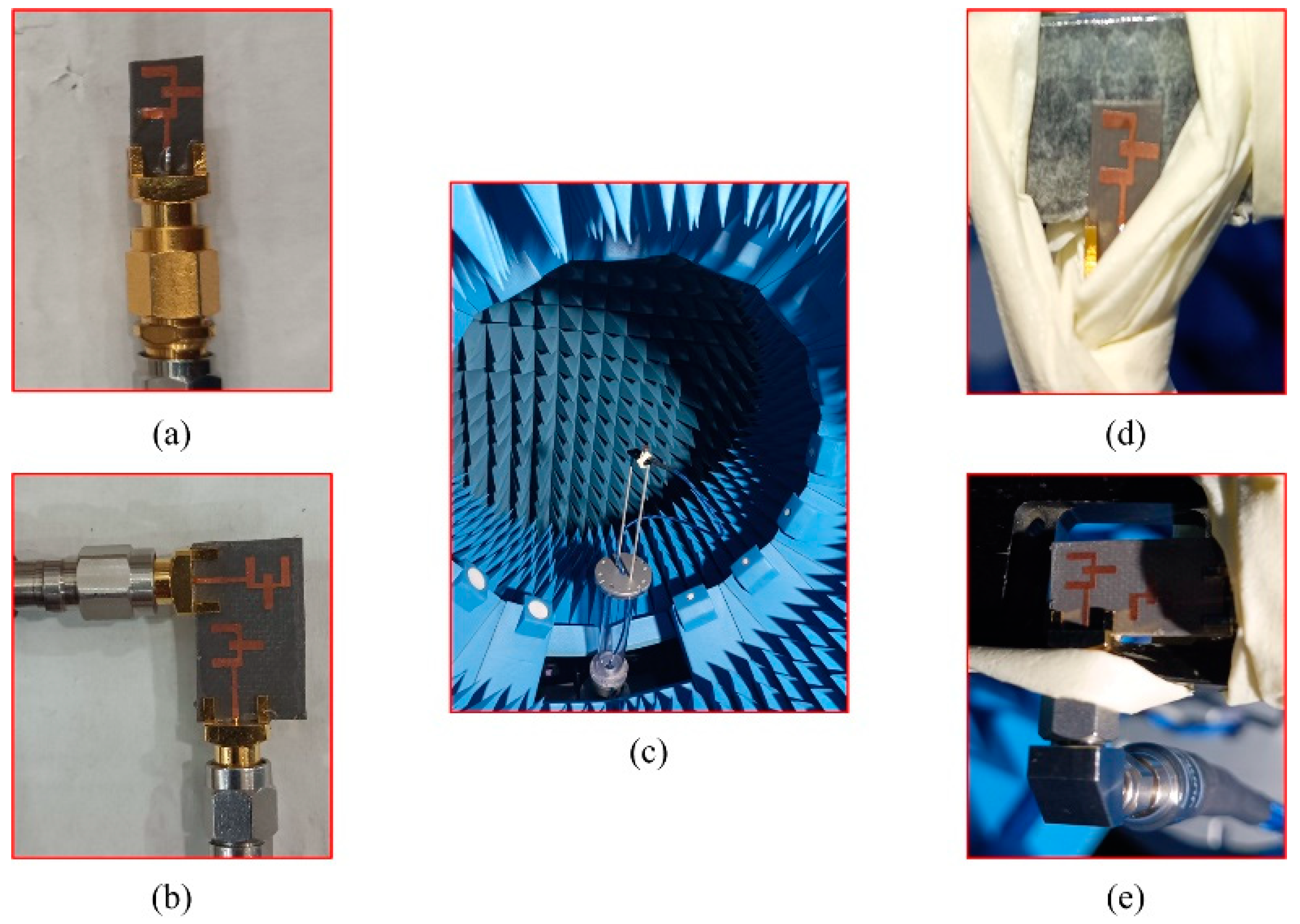
3.1. Measurement Setup
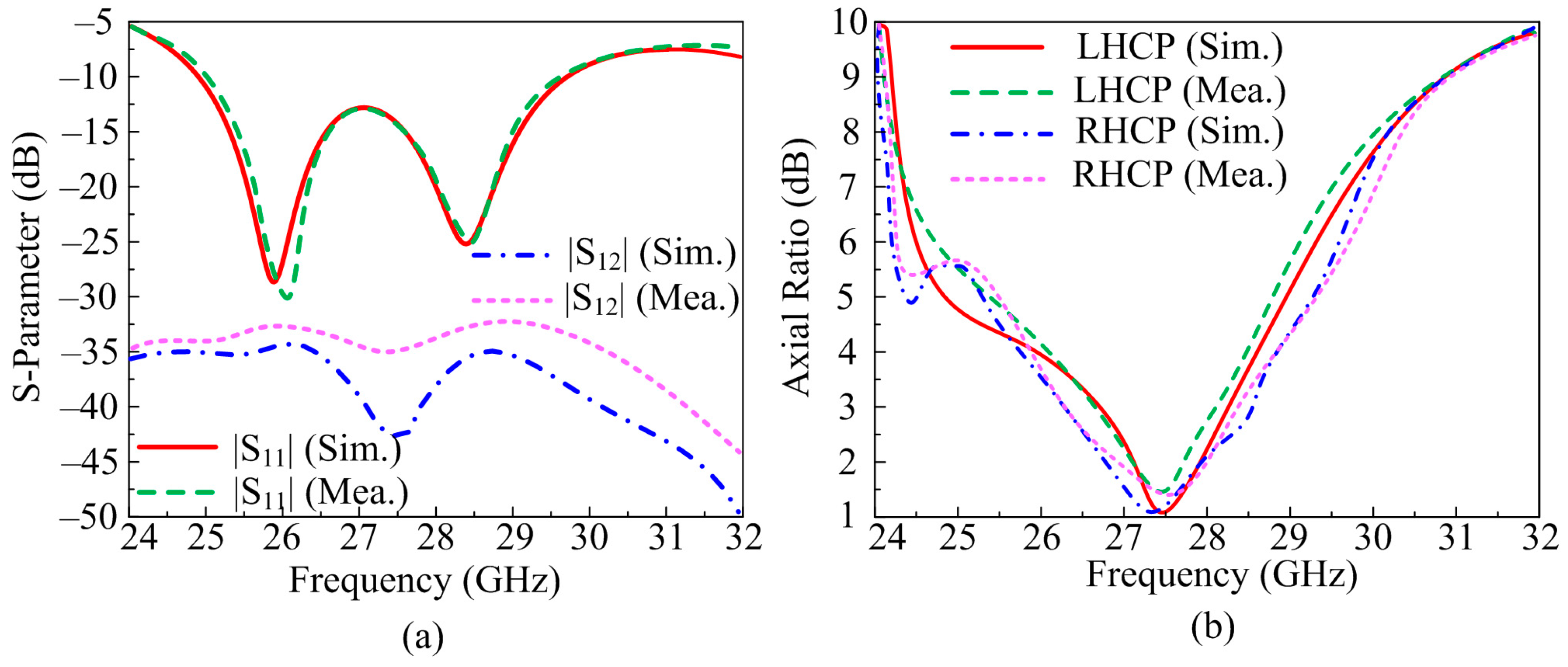
3.2. Parallel Placement
3.3. Parallel Placement with Inverted Structure
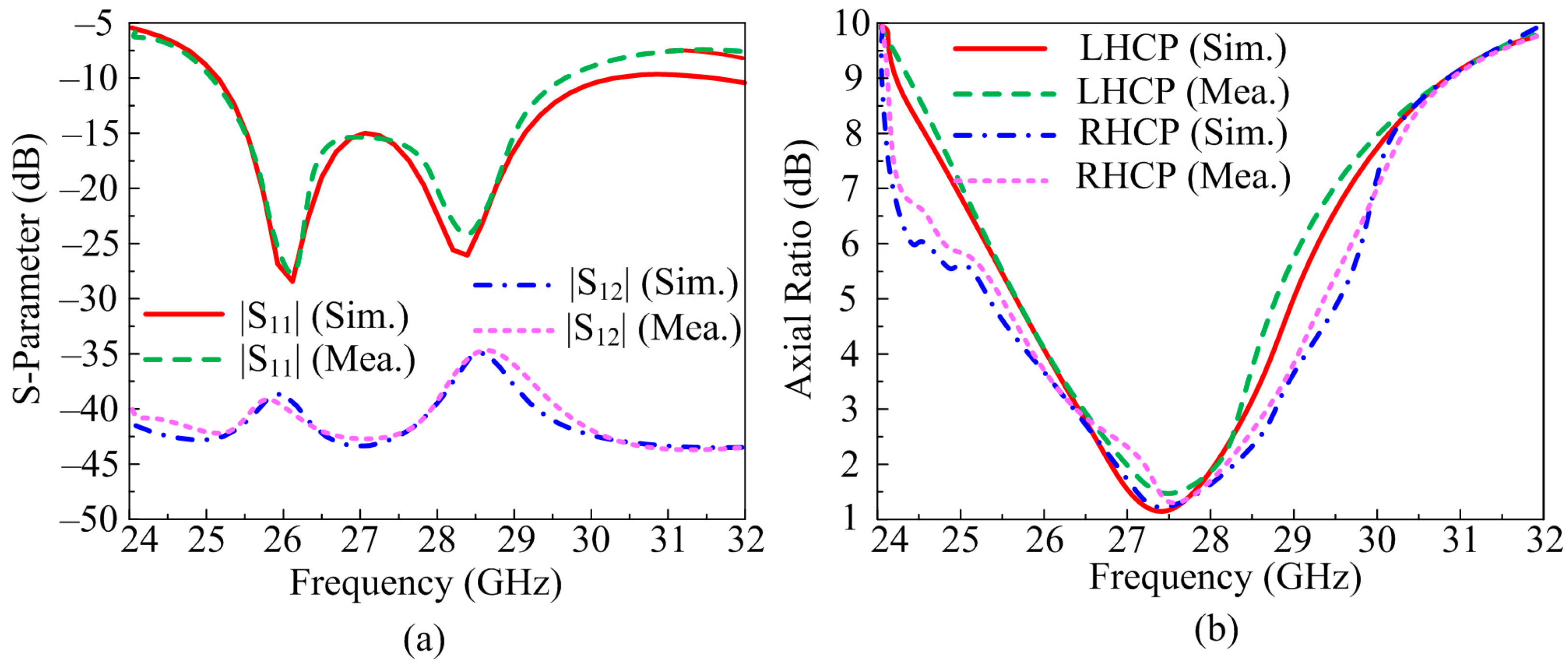
3.4. Orthognal Placement
3.5. Inverted Structure Placement
3.6. Comparison among Various MIMO Configurations
3.7. Comparison with State-of-the-Art
4. Conclusions
Author Contributions
Funding
Data Availability Statement
Acknowledgments
Conflicts of Interest
References
- Hussain, M.; Ali, E.M.; Awan, W.A.; Hussain, N.; Alibakhshikenari, M.; Virdee, B.S.; Falcone, F. Electronically reconfigurable and conformal triband antenna for wireless communications systems and portable devices. PLoS ONE 2022, 17, e0276922. [Google Scholar] [CrossRef]
- Ali, E.M.; Awan, W.A.; Naqvi, S.I.; Alzaidi, M.S.; Alzahrani, A.; Elkamchouchi, D.H.; Falcone, F.; Alharbi, T.E.A. A low-profile antenna for on-body and off-body applications in the lower and upper ISM and WLAN bands. Sensors 2023, 23, 709. [Google Scholar] [CrossRef] [PubMed]
- Ali, E.M.; Awan, W.A.; Alizaidi, M.S.; Alzahrani, A.; Elkamchouchi, D.H.; Falcone, F.; Ghoneim, S.S.M. A shorted stub loaded UWB flexible antenna for small IoT devices. Sensors 2023, 23, 748. [Google Scholar] [CrossRef] [PubMed]
- Hussain, N.; Naqvi, S.I.; Awan, W.A.; Le, T.T. A metasurface-based wideband bidirectional same-sense circularly polarized antenna. Int. J. RF Microw. Comput-Aided Eng. 2020, 30, e22262. [Google Scholar] [CrossRef]
- Chen, Q.; Li, J.Y.; Yang, G.; Cao, B.; Zhang, Z. A polarization-reconfigurable high-gain microstrip antenna. IEEE Trans. Antennas Propag. 2019, 67, 3461–3466. [Google Scholar] [CrossRef]
- Dicandia, F.A.; Fonseca, N.J.G.; Bacco, M.; Mugnaini, S.; Genovesi, S. Space-air-ground integrated 6G wireless communication networks: A review of antenna technologies and application scenarios. Sensors 2022, 22, 3136. [Google Scholar] [CrossRef]
- Berg, M.; Lighari, R.U.R.; Tuovinen, T.; Salonen, E.T. Circularly polarized GPS antenna for simultaneous LHCP and RHCP reception with high isolation. In Proceedings of the 2016 Loughborough Antennas & Propagation Conference (LAPC), Loughborough, UK, 14–15 November 2016; IEEE: Piscataway, NJ, USA, 2016; pp. 1–4. [Google Scholar]
- Khan, I.; Wu, Q.; Ullah, I.; Rahman, S.U.; Ullah, H.; Zhang, K. Designed Circularly Polarized Two-Port Microstrip MIMO Antenna for WLAN Applications. Appl. Sci. 2022, 12, 1068. [Google Scholar] [CrossRef]
- Dong, J.; Ding, C.; Mo, J. A Low-Profile Wideband Linear-to-Circular Polarization Conversion Slot Antenna Using Metasurface. Materials 2020, 13, 1164. [Google Scholar] [CrossRef]
- Le, T.T.; Park, H.-Y.; Yun, T.-Y. Simple Reconfigurable Circularly Polarized Antenna at Three Bands. Sensors 2019, 19, 2316. [Google Scholar] [CrossRef]
- Mallat, N.K.; Nouri, M.; Aghdam, S.A.; Zia, M.T.; Harb, B.; Jafarieh, A. A dual circularly reconfigurable polarization patch antenna for fifth generation mobile communication systems. Prog. Electromagn. Res. C 2020, 105, 73–84. [Google Scholar] [CrossRef]
- Martinez-de-Rioja, E.; Martinez-de-Rioja, D.; López-Sáez, R.; Linares, I.; Encinar, J.A. High-Efficiency Polarizer Reflectarray Antennas for Data Transmission Links from a CubeSat. Electronics 2021, 10, 1802. [Google Scholar] [CrossRef]
- Park, S.J.; Park, S.O. LHCP and RHCP substrate integrated waveguide antenna arrays for millimeter-wave applications. IEEE Antennas Wirel. Propag. Lett. 2016, 16, 601–604. [Google Scholar] [CrossRef]
- Ullah, U.; Al-Hasan, M.; Koziel, S.; Mabrouk, I.B. Series-slot-fed circularly polarized multiple-input–multiple-output antenna array enabling circular polarization diversity for 5G 28 GHz indoor applications. IEEE Trans. Antennas Propag. 2021, 69, 5607–5616. [Google Scholar] [CrossRef]
- Hussain, N.; Jeong, M.J.; Abbas, A.; Kim, N. Metasurface-based single-layer wideband circularly polarized MIMO antenna for 5G millimeter-wave systems. IEEE Access 2020, 8, 130293–130304. [Google Scholar] [CrossRef]
- Baghdadi, H.; Royo, G.; Bel, I.; Cortés, F.J.; Celma, S. Compact 2 × 2 Circularly Polarized Aperture-Coupled Antenna Array for Ka-Band Satcom-on-the-Move Applications. Electronics 2021, 10, 1621. [Google Scholar] [CrossRef]
- Sharma, S.; Mehra, R. A dual-band, dual-polarized, CPW-fed wideband antenna loaded with via less CRLH-MTM TL for 5G mm-Wave communication. AEU-Int. J. Electron. Commun. 2021, 141, 153950. [Google Scholar] [CrossRef]
- Kesavan, A.; Al-Hassan, M.; Ben Mabrouk, I.; Denidni, T.A. Wideband Circular Polarized Dielectric Resonator Antenna Array for Millimeter-Wave Applications. Sensors 2021, 21, 3614. [Google Scholar] [CrossRef]
- Askari, H.; Hussain, N.; Sufian, M.A.; Lee, S.M.; Kim, N. A Wideband Circularly Polarized Magnetoelectric Dipole Antenna for 5G Millimeter-Wave Communications. Sensors 2022, 22, 2338. [Google Scholar] [CrossRef]
- Wei, Y.; Arnold, C.; Hong, J.; Rao, J. Reconfigurable Wideband Linear-Polarized and Dual Left/Right-Hand Circularly-Polarized Waveguide Antennas for Beamforming Antenna array. In Proceedings of the 2022 16th European Conference on Antennas and Propagation (EuCAP), Madrid, Spain, 27 March–1 April 2022; IEEE: Piscataway, NJ, USA, 2022; pp. 1–5. [Google Scholar]
- Dicandia, F.A.; Genovesi, S.; Monorchio, A. Analysis of the performance enhancement of MIMO systems employing circular polarization. IEEE Trans. Antennas Propag. 2017, 65, 4824–4835. [Google Scholar] [CrossRef]
- Kovitz, J.M.; Rajagopalan, H.; Rahmat-Samii, Y. Design and implementation of broadband MEMS RHCP/LHCP reconfigurable arrays using rotated E-shaped patch elements. IEEE Trans. Antennas Propag. 2015, 63, 2497–2507. [Google Scholar] [CrossRef]
- Yang, Y.H.; Sun, B.H.; Guo, J.L. A single-layer wideband circularly polarized antenna for millimeter-wave applications. IEEE Trans. Antennas Propag. 2020, 68, 4925–4929. [Google Scholar] [CrossRef]
- Hussain, M.; Abbas, S.; Alibakhshikenari, M.; Dalarsson, M.; Falcone, F. Circularly Polarized Wideband Antenna for 5G Millimeter Wave Application. In Proceedings of the 2022 IEEE International Symposium on Antennas and Propagation and USNC-URSI Radio Science Meeting (AP-S/URSI), Denver, CO, USA, 10–15 July 2022; IEEE: Piscataway, NJ, USA, 2022; pp. 830–831. [Google Scholar]
- Zahra, H.; Awan, W.A.; Ali, W.A.E.; Hussain, N.; Abbas, S.M.; Mukhopadhyay, S. A 28 GHz broadband helical inspired end-fire antenna and its MIMO configuration for 5G pattern diversity applications. Electronics 2021, 10, 405. [Google Scholar] [CrossRef]
- Park, S.-H.; Jang, G.-H.; Seo, Y.-H.; Keum, H.-S.; Bang, S.-I. High-Speed Antenna Measurement System Using Multi-Probe Array Technique for 5G Applications. Electronics 2022, 11, 3435. [Google Scholar] [CrossRef]


| Antenna Design | Element Placement | Operational Bandwidth (GHz) | Transmission Co-Efficient (dB) | Maximum Axial Ratio Bandwidth (GHz) | Peak Gain (dBi) | Radiation Efficiency (%) |
|---|---|---|---|---|---|---|
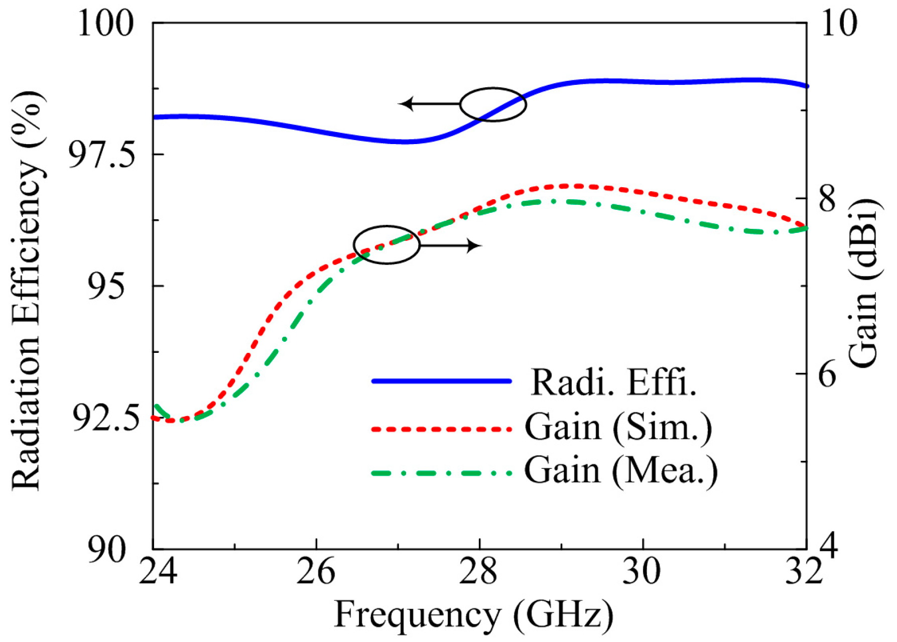
| Antenna 1 | Parallel placed | 25.25–29.25 | <−39 | 2.5 | 8.1 | 98 |
| Antenna 2 | Parallel placed with opposite direction | 25.4–29.4 | <−42 | 3 | 8.6 | 98.2 |
| Antenna 3 | Orthogonal placement | 26–29 | <−45 | 3 | 8.2 | 98 |
| Antenna 4 | Inverted placement | 25.5–30 | <−40 | 3.1 | 8.75 | 99 |
| Ref. | Antenna Size mm3 | Operating Frequency (GHz) | Bandwidth (GHz) | Gain (dBi) | Polarization Type | Axial Ratio Bandwidth (GHz) | Antenna Type and Mechanism |
|---|---|---|---|---|---|---|---|
| [11] | 19 × 17 × 0.8 | 28 38 | 27–29.5 35–38.2 | 8 8.7 | RHCP LHCP | 27.3–29 35–38.2 | Microstrip Patch antenna |
| [12] | 180 × 180 × 1.67 | 19.7 | 17.2–22.7 | - | RHCP LHCP | 17–19 | Reflect array Antenna |
| [13] | 70 × 63.5 × 2.2 | 28 | 27–29.5 | - | RHCP LHCP | 27.7–28.3 | SIW Antenna Array |
| [14] | 28.7 × 27 × 2.5 | 28 | 26.9–30.7 | 11.86 | CP | 27.3–29.65 | Series slot fed MIMO array |
| [15] | 20.4 ×20.4 × 0.5 | 27.5 | 24.5–31 | 11 | CP | 25–29.3 | Meta-surface-based antenna |
| [17] | 10 × 10 × 0.51 | 32 | 28–39.2 | 12 | CP LP | 34–38 | CPW fed Antenna with CRLH-MTM |
| [18] | 20 × 20 × 0.254 | 30 | 26.5–34.7 | 9.5 | RHCP LHCP | 28.5–32 | DRA array |
| [19] | 10 × 10 × 15 | 28 | 24.2–30.4 | 8.5 | CP | 24.5–30 | ME dipole Antenna |
| [22] | 10 × 10 × 2.199 | 28 | 27.7–29.55 | - | RHCP LHCP | 27.7–29.25 | SIW Array Antenna |
| This Work | 20.5 × 12 × 0.79 | 28 | 25.5–30 | 8.75 | RHCP LHCP | 25.2–28.3 | MIMO Configuration |
Disclaimer/Publisher’s Note: The statements, opinions and data contained in all publications are solely those of the individual author(s) and contributor(s) and not of MDPI and/or the editor(s). MDPI and/or the editor(s) disclaim responsibility for any injury to people or property resulting from any ideas, methods, instructions or products referred to in the content. |
© 2023 by the authors. Licensee MDPI, Basel, Switzerland. This article is an open access article distributed under the terms and conditions of the Creative Commons Attribution (CC BY) license (https://creativecommons.org/licenses/by/4.0/).
Share and Cite
Taher, F.; Hamadi, H.A.; Alzaidi, M.S.; Alhumyani, H.; Elkamchouchi, D.H.; Elkamshoushy, Y.H.; Haweel, M.T.; Sree, M.F.A.; Fatah, S.Y.A. Design and Analysis of Circular Polarized Two-Port MIMO Antennas with Various Antenna Element Orientations. Micromachines 2023, 14, 380. https://doi.org/10.3390/mi14020380
Taher F, Hamadi HA, Alzaidi MS, Alhumyani H, Elkamchouchi DH, Elkamshoushy YH, Haweel MT, Sree MFA, Fatah SYA. Design and Analysis of Circular Polarized Two-Port MIMO Antennas with Various Antenna Element Orientations. Micromachines. 2023; 14(2):380. https://doi.org/10.3390/mi14020380
Chicago/Turabian StyleTaher, Fatma, Hussam Al Hamadi, Mohammed S. Alzaidi, Hesham Alhumyani, Dalia H. Elkamchouchi, Yasser H. Elkamshoushy, Mohammad T. Haweel, Mohamed Fathy Abo Sree, and Sara Yehia Abdel Fatah. 2023. "Design and Analysis of Circular Polarized Two-Port MIMO Antennas with Various Antenna Element Orientations" Micromachines 14, no. 2: 380. https://doi.org/10.3390/mi14020380