
Post-Electric Current Treatment Approaching High-Performance Flexible n-Type Bi2Te3 Thin Films

1
School of Machinery and Automation, Weifang University, Weifang 261061, China
2
Australian Institute for Bioengineering and Nanotechnology, The University of Queensland, St Lucia, Brisbane, QLD 4072, Australia
3
School of Materials Science and Engineering, Inner Mongolia University of Technology, Hohhot 010051, China
4
Shenzhen Key Laboratory of Advanced Thin Films and Applications, Key Laboratory of Optoelectronic Devices and Systems of Ministry of Education and Guangdong Province, College of Physics and Optoelectronic Engineering, Shenzhen University, Shenzhen 518060, China
*
Author to whom correspondence should be addressed.
†
These authors contributed equally to this work.
Micromachines 2022, 13(9), 1544; https://doi.org/10.3390/mi13091544
Submission received: 1 September 2022
/
Revised: 12 September 2022
/
Accepted: 15 September 2022
/
Published: 17 September 2022
(This article belongs to the Special Issue Advances in Nanostructured Thermoelectric Materials and Devices)
Abstract
:Inorganic n-type Bi2Te3 flexible thin film, as a promising near-room temperature thermoelectric material, has attracted extensive research interest and application potentials. In this work, to further improve the thermoelectric performance of flexible Bi2Te3 thin films, a post-electric current treatment is employed. It is found that increasing the electric current leads to increased carrier concentration and electric conductivity from 1874 S cm−1 to 2240 S cm−1. Consequently, a high power factor of ~10.70 μW cm−1 K−2 at room temperature can be achieved in the Bi2Te3 flexible thin films treated by the electric current of 0.5 A, which is competitive among flexible n-type Bi2Te3 thin films. Besides, the small change of relative resistance <10% before and after bending test demonstrates excellent bending resistance of as-prepared flexible Bi2Te3 films. A flexible device composed of 4 n-type legs generates an open circuit voltage of ~7.96 mV and an output power of 24.78 nW at a temperature difference of ~35 K. Our study indicates that post-electric current treatment is an effective method in boosting the electrical performance of flexible Bi2Te3 thin films.
1. Introduction
Flexible thermoelectric (TE) devices, with the advantages of being self-powering, sustainable, and of small volume, provide a reliable power supply solution for wearable electronics, implantable electronics, and chip-sensors at near-room temperature [1,2,3]. The main challenge for flexible TE devices lies in the TE material performance and device integration technology. The performance of TE materials is evaluated by dimensionless figure-of-merit ZT (ZT = S2σT/κ, where S, σ, S2σ, T, and κ represent Seebeck coefficient, electrical conductivity, power factor, absolute temperature, and thermal conductivity, respectively) [4,5]. Recently, the flexible thin film (f-TF) provides an avenue for flexible TE devices due to the excellent flexibility, comparing with the bulk TE counterparts [6,7]. Organic f-TFs, including P3HT (S2σ < ~0.04 μW cm−1 K−2 at room temperature) [8], PEDOT:PSS (S2σ < ~0.5 μW cm−1 K−2 at 300 K) [9], and PANI (S2σ < ~0.6 μW cm−1 K−2 at 300 K) [10], are typically highly flexible with relatively low TE performance compared with the inorganic f-TFs. Inorganic f-TFs with excellent TE performance have received extensive attention, such as SnSe (S2σ = ~3.5 μW cm−1 K−2 at 300 K) [11], CuI (S2σ = ~3.75 μW cm−1 K−2 at 300 K) [12], Ca0.35CoO2 (S2σ = ~0.5 μW cm−1 K−2 at 300 K) [13], Ag2Se (S2σ = ~9.874 μW cm−1 K−2 at 300 K) [14], and Bi2Te3-based f-TFs (S2σ = ~25 μW cm−1 K−2 at 300 K) [15].
Among many inorganic f-TFs, Bi2Te3 based ones are the most widely applied due to the excellent TE performance at room temperature [16,17]. Wu et al. [18] reported that hybridizing Bi2Te3 f-TFs with graphene oxide by vacuum filtration and annealing, and an S2σ of ~1.08 μW cm−1 K−2, is approached at ~297 K. Chen et al. [19] successful prepared Bi2Te3 nanowire-based f-TFs with an S2σ o of 1.10 μW cm−1 K−2 at 400 K by solution phase printing methods. Madan et al. [20] successfully fabricated Se-doped Bi2Te3 based f-TFs with the S2σ of ~2.65 μW cm−1 K−2 at ~297 K by mechanically alloyed and dispense printing method. Bi2Te3 f-TFs fabricated by in situ solution method has approached ~7.4 μW cm−1 K−2 at ~297 K [21]. Bi2Te3 f-TFs fabricated by thermal diffusion methods can achieve the S2σ of ~14.65 μW cm−1 K−2 at room temperature [22]. Additionally, many post-treatment techniques have been used to further improve the TE performance of n-type Bi2Te3 based f-TFs, such as such as heat treatment [23], laser treatment [24,25], infrared treatment [26], and electric current treatment [27].
Electric current treatment, as an effective and fast method, has attracted research interest [28]. Tan et al. [29] strengthened the anisotropy of electron mobility of Bi2Te3 based thin films by introducing electric current during the deposition process, and achieved a high S2σ of 45 μW cm−1 K−2. Zhu et al. [27] also used post-electric current treatment (P-ECT) methods to optimize phase transformations and crystal orientation of Bi0.5Sb1.5Te3 thin film, resulting in an increase in σ. It is typically understood that P-ECT can enhance the recrystallization kinetics, promote dislocation movement, and facilitate the formation of oriented microstructures in a short time [30,31]. It was worth mentioning that the thermal annealing effect is Joule thermal effect, and the athermal effect was mainly attributed to the electronic wind on atom diffusion [31]. Further research will analyze the effect of thermal effect and athermal effect on the doped Bi2Te3 f-TFs, respectively.
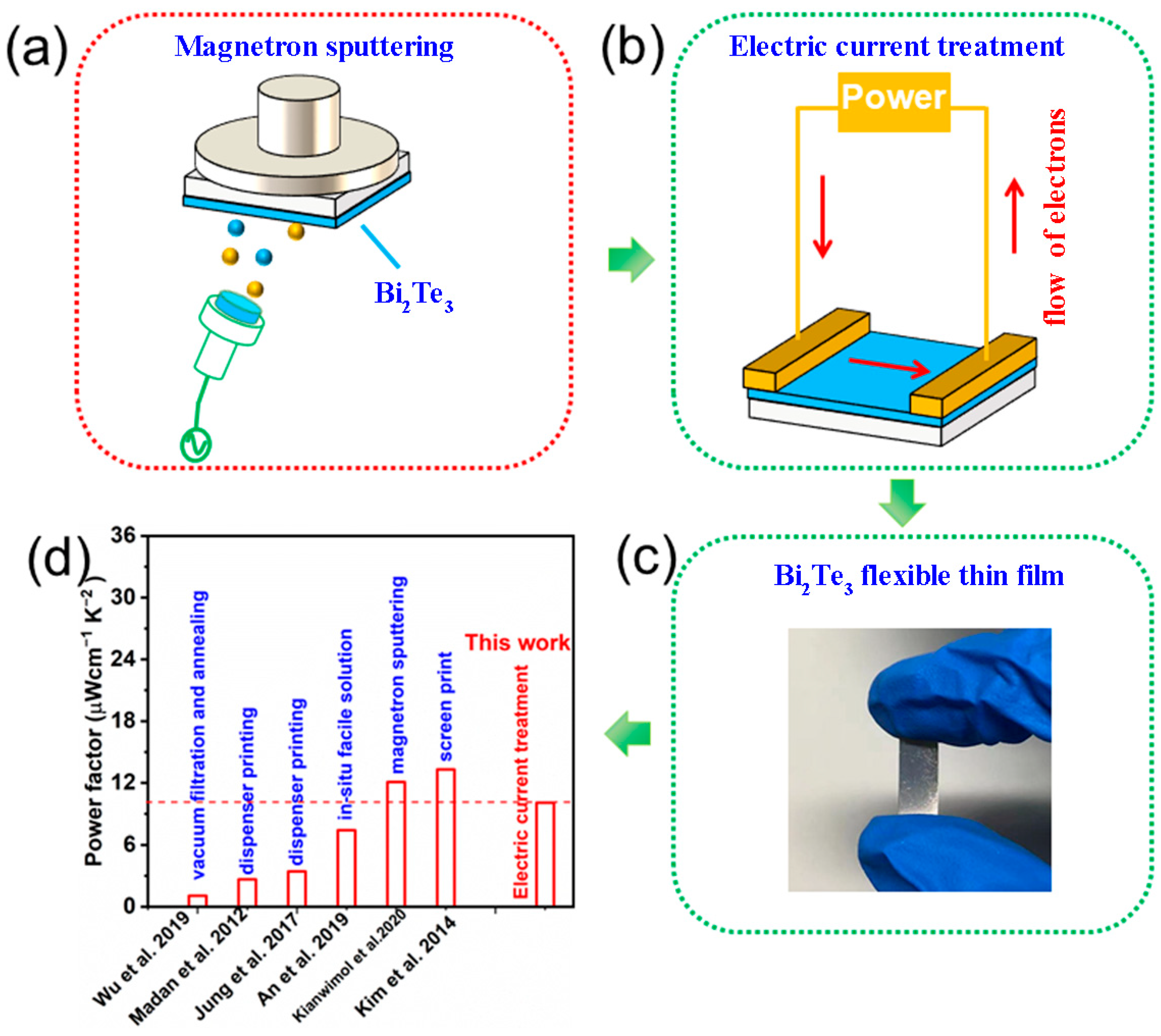
In this study, the magnetron sputtering is combined with P-ECT to prepare n-type Bi2Te3 f-TF on polyimide (PI) substrate (Figure 1a,b). Figure 1c shows an optical image of a typical n-type Bi2Te3 f-TF. Through optimizing the P-ECT current, the increase of carrier concentration (ne) is achieved, leading to a high σ of ~2065 S cm−1. The corresponding S2σ is ~10.70 μW cm−1 K−2, which is comparable with the reported n-type Bi2Te3 f-TF (Figure 1d). Applications of as-prepared n-type Bi2Te3 f-TFs were investigated via an assembled TE device, which is composed of 4 n-type Bi2Te3 legs. The device can generate the maximum open circuit voltage of ~7.96 mV and the maximum output power of 24.78 nW at the temperature difference (∆T) of ~35 K.
2. Experimental Section
The n-type Bi2Te3 f-TFs were deposited on a flexible PI substrate using a magnetron sputtering method. The deposition parameters of the thin film are presented as follows: the working pressure of 1 Pa, radio frequency sputtering power of 50 W, the sputtering temperature of 573 K, the background vacuum of 7.0 × 10⁻⁴ Pa, and argon flow of 40 Sccm. The KPS-3005D generator with the maximum output of 5.000 A was used to provide an electric pulse current. Bi2Te3 f-TFs were post-treated by electric current with duration of 1 s and interval of 1 s. The electric current was set as 0.3 A, 0.5 A, and 0.6 A, respectively, and the electric current time was 10 min. The thickness range of the Bi2Te3 f-TFs was ~580 nm. Finally, the flexible thermoelectric device was assembled with 4 n-type single-legs.
X-ray diffraction (XRD, D/max 2500 Rigaku Corporation, Tokyo, Japan, CuKα radiation) was employed to investigate the crystal structures of as-prepared Bi2Te3 f-TFs. SEM (Zeiss supra 55) was used to characterize the surface morphology. EDS (Bruker Quantax 200) was used to analyze the compositions of Bi2Te3 f-TFs. Hall measurement system (HL5500PC, Nano metrics) was employed to record ne and mobility (μ) values. A profilometer (Dektak XT, BRUKER, Germany) was employed to measure the thickness of flexible n-type Bi2Te3 thin films. And σ and S were simultaneously measured by the SBA458 (Nezsch, Germany).
3. Results and Discussion
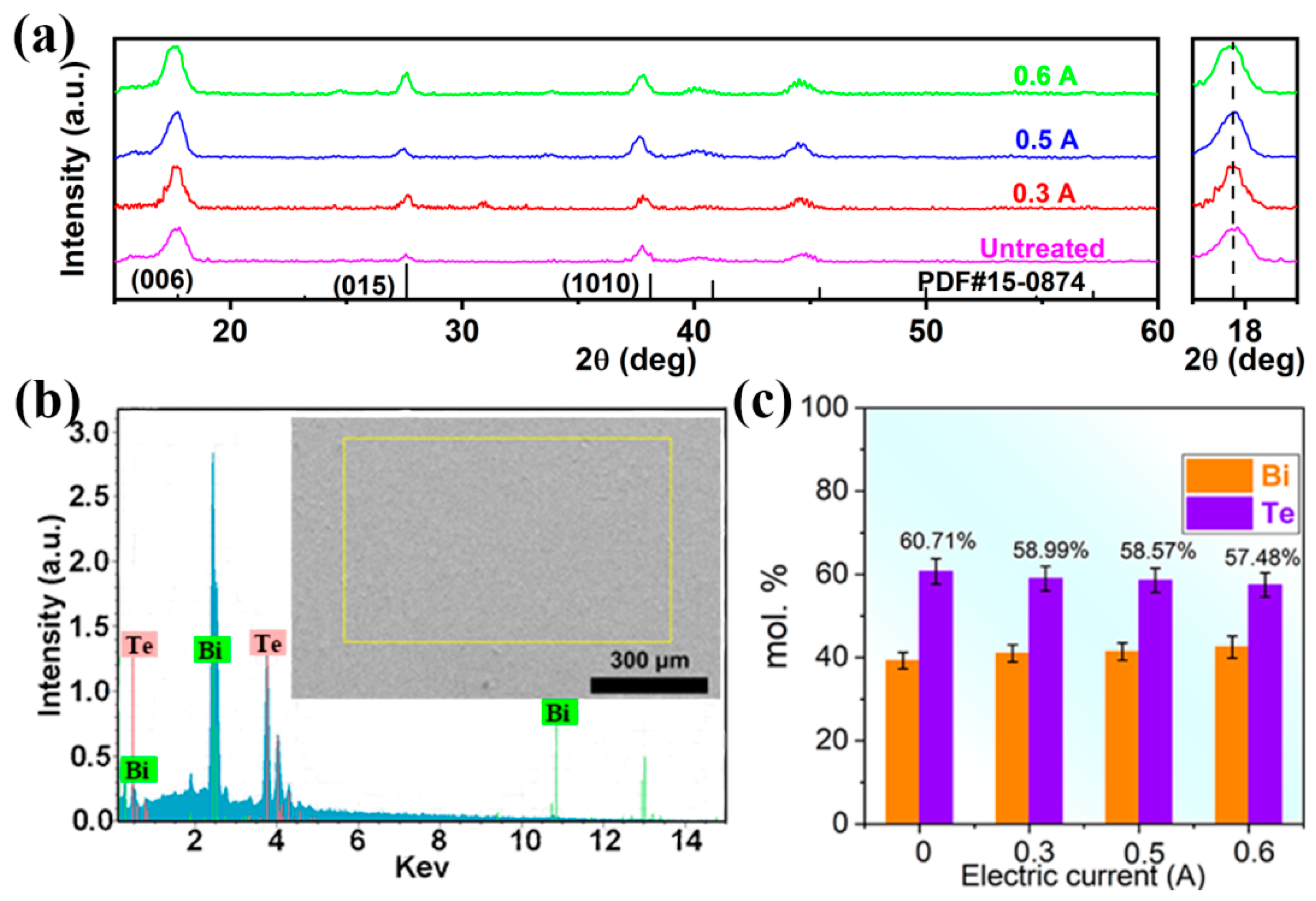
XRD patterns were employed to analyze the crystal structure of as-prepared Bi2Te3 f-TFs as shown in Figure 2a. As can be seen, all the diffraction peaks can be indexed as the Bi2Te3 (PDF#15-0874), and no impurity peaks were observed. The right inset of Figure 2a shows the enlarged (006) peaks. The strongest peaks of all XRD patterns can be indexed as (006), indicating (00l) preferred orientation of all as-prepared Bi2Te3 f-TFs. Figure S1 shows that no obvious crystallinity changes have been observed due to similar peak intensity and Full-Width Half-Maximum. Figure 2b shows a typical SEM-EDS pattern of Bi2Te3 f-TFs treated under the electric current of 0.5 A. The chemical compositions of as-prepared Bi2Te3 f-TFs are shown in Figure 2c and Table 1. Before P-ECT, the as-deposited Bi2Te3 f-TF presents the standard chemical stoichiometric ratio of ~2:3. With the increase of electric current, the Te content decreases due to the release of the unstable Te. With increasing the electric current from 0 to 0.6 A, the Bi content increases from 39.29 to 42.52 at. %, and Te content decreases from 60.71 to 57.48 at. %, indicating the increasing content of Te vacancies
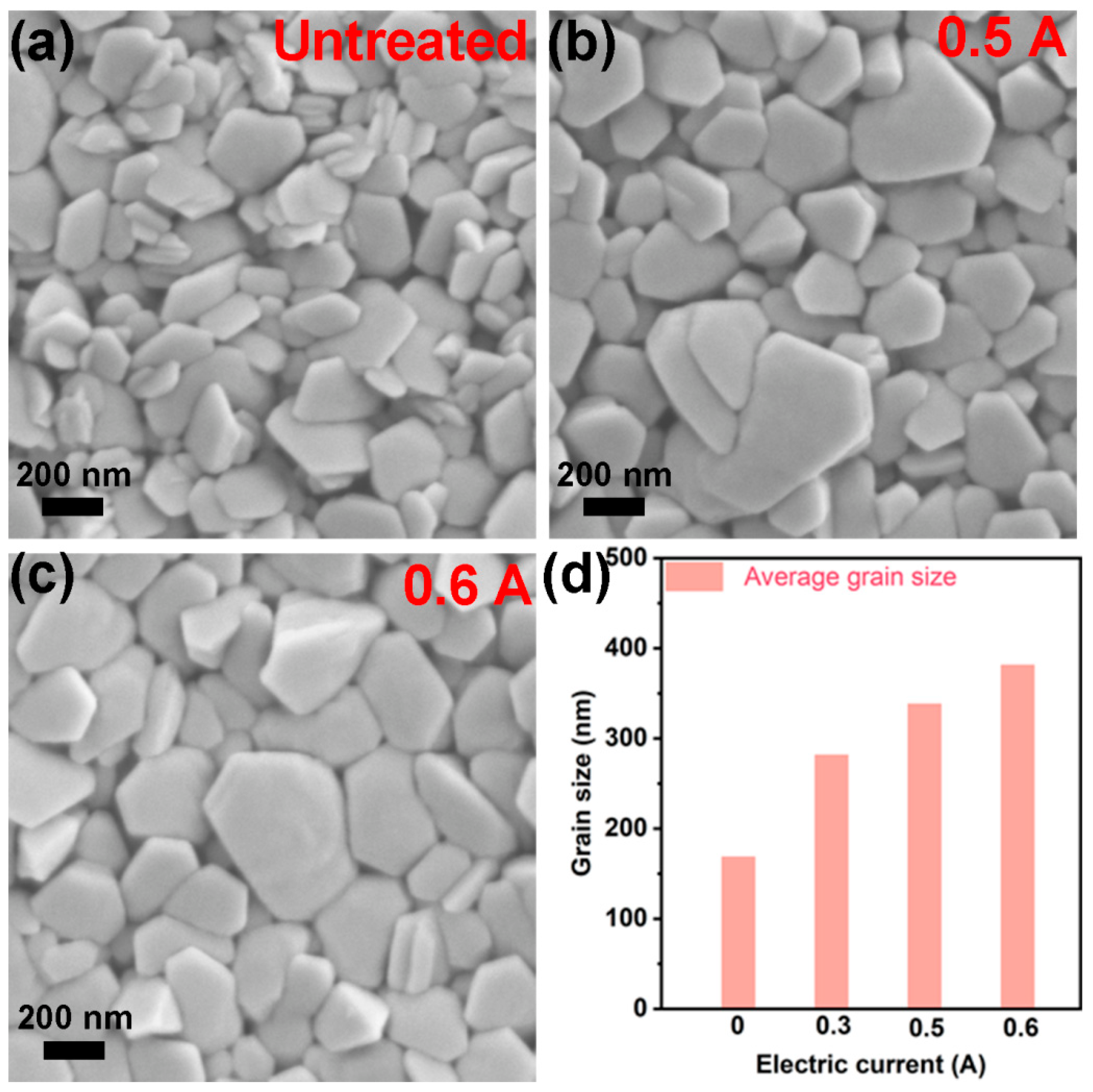
To characterize the morphology of Bi2Te3 grains, the SEM images of as-prepared Bi2Te3 f-TFs treated under the electric current 0, 0.5, and 0.6 A are shown in Figure 3a–c, respectively. As can be seen, the as-prepared BT f-TFs are composed of hexagonal flakes stacking parallel to substrate. As the electric current increases from 0 A to 0.6 A, larger Bi2Te3 grains can be observed. Figure 3d shows the average grain size of as-prepared Bi2Te3 f-TF as a function of electric current. With the increasing of the electric current from 0 to 0.6 A, the average grain size increased from ~168 to ~381 nm. Figure S2 compares the morphologies of as-prepared 0.6 A-Bi2Te3 thin film before and after cycling measurement of TE performance, where no obvious difference has been observed, indicating excellent stability. The grain growth with increasing electric current can be attributed to the additional energy supply from post-electric treatment [28,30].
Room temperature TE performance of as-prepared Bi2Te3 f-TFs is shown in Figure 4. Figure 4a shows the room temperature σ, S, and S2σ for Bi2Te3 f-TF as a function of electric current. The σ increases from 1874 to 2240 S cm−1 with increasing the electric current from 0 to 0.6 A, and the |S| decreases from 74 to 61 μV K−1. To better understand the change of S and σ, the ne was measured as shown in Figure 4b. The ne increases from 2.03 × 10²⁰ to 3.84 × 1020 cm−3 with the increase of electric current. A simple relationship between ne and S can be exhibited by Mott formula [35]:
where KB, e, h, and m*DOS present Boltzmann constant, electron, Planck Constant, and, the density of state’s effective mass, respectively. The reduced |S| is attributed to the increase of ne according to their inverse relationship between S and ne as expressed in Equation (1). Furthermore, according to the relationship between σ and ne as expressed in formula σ = μene, the increase of σ is mainly attributed to the increase of ne. It is worth mentioning that the |S| of Bi2Te3 f-TFs is still lower than that of bulk materials due to the high ne > 1 × 10²⁰ (detailed discussion in Supplementary Materials). And the increased ne should be mainly attributed to the increased amount of Te vacancies with increasing the electrical current. The room temperature S2σ of Bi2Te3 f-TF as a function of electric current is shown in Figure 4a. The maximum S2σ of ~10.70 μW cm−1 K−2 can be achieved mainly due to the high σ of ~2065 S cm−1 and moderate S of −72 μV K−1. The TE performance tests of the 0.5 A-Bi2Te3 f-TF were repeated 3 times to verify the stability of as-prepared Bi2Te3 f-TFs as shown in Figure S3. Nearly unchanged TE performance during successive measurement cycles indicates high stability of our Bi2Te3 f-TFs. Element-doped Bi2Te3 based thin films usually have higher S2σ [36,37,38], and further research will analyze the effect of the electric current treatment on the doped Bi2Te3 f-TFs.
The bending tests were employed to investigate the bending resistance of as-prepared n-type Bi2Te3 f-TFs. Figure 5a,b shows the change of relative resistance (∆R/R0) as a function of bending cycles and bending radius, respectively. With the increase of cycles from 200 to 1000 under the bending radius of 9 mm, the ∆R/R0 increases from 3.39% to 8.34% as shown in Figure 5a. In addition, with the increase of bending radius from 7 mm to 13 mm, the ∆R/R0 decreases from 9.98% to 2.41% as shown in Figure 5b. The ∆R/R0 < 10% suggests that the Bi2Te3 f-TFs possess excellent bending resistance [22,39]. Figure S4 shows the repetitive test result of the bending resistance before and after cycling TE performance measurement, where high mechanical stability has been demonstrated. To demonstrate the practical applicability of Bi2Te3 f-TFs, a flexible TE device assembled of 4 Bi2Te3 legs (treated under the electric current of 0.5 A) was fabricated as schematically shown in the inset of Figure 5c. And Figure 5c shows the open circuit voltage and output power as a function of electric current at the temperature difference (∆T) ranging from 10 to 35 K. And a high temperature difference can be easily maintained between hot and cold side of thin films devices due to the polymide substrate (κ < 1 W m−1 K−1) [40]. As can be seen, the maximum open circuit voltage of ~7.96 mV can be achieved with the corresponding output power of 24.78 nW at ∆T of 35 K. The performance of the flexible TE device can be evaluated by power density Pdensity (Pdensity = Pmax/w·h, where w and h represent the width and height, respectively) [40,41]. Figure 5d shows that the Pdensity of the flexible TE device is 0.04 mW cm−2, 0.17 mW cm−2 and 0.36 mW cm−2, corresponding to the ∆T of 10, 20 and 30 K, respectively.
4. Conclusions
In conclusion, we have successfully improved n-type Bi2Te3 f-TFs by P-ECT. It is found that, with the increase of electric current, the ne increases and σ increases from 1874 to 2240 S cm−1. Consequently, the high S2σ of the Bi2Te3 f-TFs treated by 0.5 A achieves ~10.70 μW cm−1 K−2 at room temperature, which is competitive among the reported n-type Bi2Te3 f-TFs. Besides, a small ∆R/R0 < 10% is achieved after bending test, suggesting high bending resistance of our prepared Bi2Te3 f-TFs. Subsequently, a flexible TE device composed of 4 n-type single legs generates an open circuit voltage of ~7.96 mV and an output power is 24.78 nW at ΔT of ~35 K. Our work demonstrates that P-ECT method can effectively further improve the electrical performance of Bi2Te3 f-TFs.
Supplementary Materials
The following supporting information can be downloaded at: www.mdpi.com/article/10.3390/mi13091544/s1, Fgiure S1: Calculated crystallinity of 0.5 A-Bi2Te3 f-TF; Fgiure S2: (a) The SEM; Figure S3: The repetitive test of TE performance of the 0.5 A-Bi2Te3 thin film; Fgiure S4: (a,b) The repetitive test result of the bending resistance of 0.5 A-Bi2Te3 thin film at bending radius of 9 mm and bending cycle of 800, respectively. References [42,43] are cited in the Supplementary Materials.
Author Contributions
D.A.: Investigation, Conceptualization, Methodology, Formal analysis, writing—original draft. W.-D.L.: Conceptualization, Project administration, Formal analysis, writing—original draft. F.M.: Investigation, Data curation, Validation. W.B.: writing—review & editing. Y.C.: writing—review & editing. All authors have read and agreed to the published version of the manuscript.
Funding
The authors would like to acknowledge the financial support from Doctoral Research Start-up Foundation of Weifang University (2023BS01).
Data Availability Statement
The processed data required to reproduce these findings cannot be shared at this time as the data also forms part of an ongoing study.
Conflicts of Interest
The authors declare no conflict of interest.
References
- Zhou, Q.; Zhu, K.; Li, J.; Li, Q.; Deng, B.; Zhang, P.; Wang, Q.; Guo, C.; Wang, W.; Liu, W. Leaf Inspired Flexible Thermoelectric Generators with High Temperature Difference Utilization Ratio and Output Power in Ambient Air. Adv. Sci. 2021, 8, 2004947. [Google Scholar] [CrossRef] [PubMed]
- Lu, Y.; Qiu, Y.; Cai, K.; Li, X.; Gao, M.; Jiang, C.; He, J. Ultrahigh performance PEDOT/Ag2Se/CuAgSe composite film for wearable thermoelectric power generators. Mater. Today Phys. 2020, 14, 100223. [Google Scholar] [CrossRef]
- Kobayashi, A.; Konagaya, R.; Tanaka, S.; Takashiri, M. Optimized structure of tubular thermoelectric generators using n-type Bi2Te3 and p-type Sb2Te3 thin films on flexible substrate for energy harvesting. Sens. Actuators A 2020, 313, 112199. [Google Scholar] [CrossRef]
- Liu, W.D.; Wang, D.Z.; Liu, Q.F.; Zhou, W.; Shao, Z.P.; Chen, Z.G. High-Performance GeTe-Based Thermoelectrics: From Materials to Devices. Adv. Energy Mater. 2020, 10, 2000367. [Google Scholar] [CrossRef]
- Liu, W.D.; Shi, X.L.; Moshwan, R.; Yang, L.; Chen, Z.G.; Zou, J. Solvothermal synthesis of high-purity porous Cu1.7Se approaching low lattice thermal conductivity. Chem. Eng. J. 2019, 375, 121996. [Google Scholar] [CrossRef]
- Shi, X.L.; Zou, J.; Chen, Z.G. Advanced Thermoelectric Design: From Materials and Structures to Devices. Chem. Rev. 2020, 120, 7399–7515. [Google Scholar] [CrossRef]
- Yang, Q.Y.; Yang, S.Q.; Qiu, P.F.; Peng, L.M.; Wei, T.R.; Zhang, Z.; Shi, X.; Chen, L.D. Flexible thermoelectrics based on ductile semiconductors. Science 2022, 377, 854–858. [Google Scholar] [CrossRef]
- He, M.; Ge, J.; Lin, Z.; Feng, X.; Wang, X.; Lu, H.; Yang, Y.; Qiu, F. Thermopower enhancement in conducting polymer nanocomposites via carrier energy scattering at the organic–inorganic semiconductor interface. Energy Environ. Sci. 2012, 5, 8351. [Google Scholar] [CrossRef]
- Jiang, F.X.; Xiong, J.H.; Zhou, W.Q.; Liu, C.C.; Wang, L.Y.; Zhao, F.; Liu, H.X.; Xu, J.K. Use of organic solvent assisted exfoliated MoS2 for optimizing the thermoelectric performance of flexible PEDOT PSS thin films. J. Mater. Chem. A 2016, 4, 5265–5273. [Google Scholar] [CrossRef]
- Wang, L.; Yao, Q.; Bi, H.; Huang, F.; Wang, Q.; Chen, L. PANI/graphene nanocomposite films with high thermoelectric properties by enhanced molecular ordering. J. Mater. Chem. A 2015, 3, 7086–7092. [Google Scholar] [CrossRef]
- Rongione, N.A.; Li, M.; Wu, H.; Nguyen, H.D.; Kang, J.S.; Ouyang, B.; Xia, H.; Hu, Y. High Performance Solution Processable Flexible SnSe Nanosheet Films for Lower Grade Waste Heat Recovery. Adv. Electron. Mater. 2019, 5, 1800774. [Google Scholar] [CrossRef]
- Yang, C.; Souchay, D.; Kneiss, M.; Bogner, M.; Wei, H.M.; Lorenz, M.; Oeckler, O.; Benstetter, G.; Fu, Y.Q.; Grundmann, M. Transparent flexible thermoelectric material based on non-toxic earth-abundant p-type copper iodide thin film. Nat. Commun. 2017, 8, 16076. [Google Scholar] [CrossRef] [PubMed]
- Sinha, T.K.; Lee, J.; Kim, J.K.; Ray, S.K.; Paul, B. Rapid growth of fully-inorganic flexible CaxCoO2 thin films from a ligand free aqueous precursor ink for thermoelectric applications. Chem. Commun. 2019, 55, 7784–7787. [Google Scholar] [CrossRef]
- Ding, Y.; Qiu, Y.; Cai, K.; Yao, Q.; Chen, S.; Chen, L.; He, J. High performance n-type Ag2Se film on nylon membrane for flexible thermoelectric power generator. Nat. Commun. 2019, 10, 841. [Google Scholar] [CrossRef] [PubMed]
- Shang, H.J.; Ding, F.Z.; Deng, Y.; Zhang, H.; Dong, Z.B.; Xu, W.J.; Huang, D.X.; Gu, H.W.; Chen, Z.G. Highly (00l)-oriented Bi2Te3/Te heterostructure thin films with enhanced power factor. Nanoscale 2018, 10, 20189–20195. [Google Scholar] [CrossRef]
- Jin, Q.; Jiang, S.; Zhao, Y.; Wang, D.; Qiu, J.; Tang, D.M.; Tan, J.; Sun, D.M.; Hou, P.X.; Chen, X.Q.; et al. Flexible layer-structured Bi2Te3 thermoelectric on a carbon nanotube scaffold. Nat. Mater. 2019, 18, 62–68. [Google Scholar] [CrossRef]
- Li, Y.; Zhao, Y.; Qiao, J.; Jiang, S.; Qiu, J.; Tan, J.; Zhang, L.; Gai, Z.; Tai, K.; Liu, C. A Flexible and Infrared-Transparent Bi2Te3-Carbon Nanotube Thermoelectric Hybrid for both Active and Passive Cooling. ACS Appl. Electron. Mater. 2020, 2, 3008–3016. [Google Scholar] [CrossRef]
- Wu, B.; Guo, Y.; Hou, C.; Zhang, Q.; Li, Y.; Wang, H. High Performance Flexible Thermoelectric Devices Based on All-Inorganic Hybrid Films for Harvesting Low-Grade Heat. Adv. Funct. Mater. 2019, 29, 1900304. [Google Scholar] [CrossRef]
- Chen, B.; Kruse, M.; Xu, B.; Tutika, R.; Zheng, W.; Bartlett, M.D.; Wu, Y.; Claussen, J.C. Flexible thermoelectric generators with inkjet-printed bismuth telluride nanowires and liquid metal contacts. Nanoscale 2019, 11, 5222–5230. [Google Scholar] [CrossRef]
- Madan, D.; Wang, Z.Q.; Chen, A.; Juang, R.C.; Keist, J.; Wright, P.K.; Evans, J.W. Enhanced performance of dispenser printed MA n-type Bi(2)Te(3) composite thermoelectric generators. ACS Appl. Mater. Interfaces 2012, 4, 6117–6124. [Google Scholar] [CrossRef]
- Jung, Y.S.; Jeong, D.H.; Kang, S.B.; Kim, F.; Jeong, M.H.; Lee, K.S.; Son, J.S.; Baik, J.M.; Kim, J.S.; Choi, K.J. Wearable solar thermoelectric generator driven by unprecedentedly high temperature difference. Nano Energy 2017, 40, 663–672. [Google Scholar] [CrossRef]
- Ao, D.W.; Liu, W.D.; Chen, Y.X.; Wei, M.; Jabar, B.; Li, F.; Shi, X.L.; Zheng, Z.H.; Liang, G.X.; Zhang, X.H.; et al. Novel Thermal Diffusion Temperature Engineering Leading to High Thermoelectric Performance in Bi2 Te3 -Based Flexible Thin-Films. Adv. Sci. 2021, 9, e2103547. [Google Scholar] [CrossRef] [PubMed]
- Zheng, Z.H.; Fan, P.; Liang, G.X.; Zhang, D.P.; Cai, X.M.; Chen, T.B. Annealing temperature influence on electrical properties of ion beam sputtered Bi2Te3 thin films. J. Phys. Chem. Solids 2010, 71, 1713–1716. [Google Scholar] [CrossRef]
- Tsay, C.Y.; Wang, M.C. Structural and optical studies on sol–gel derived ZnO thin films by excimer laser annealing. Ceram. Int. 2013, 39, 469–474. [Google Scholar] [CrossRef]
- Escola, F.Z.; Mingolo, N.; Martinez, O.E.; Rocca, J.J.; Menoni, C.S. Investigation of laser annealing mechanisms in thin film coatings by photothermal microscopy. Opt. Express 2019, 27, 5729–5744. [Google Scholar] [CrossRef] [PubMed]
- Fan, P.; Zhang, P.C.; Liang, G.X.; Li, F.; Chen, Y.X.; Luo, J.T.; Zhang, X.H.; Chen, S.; Zheng, Z.H. High-performance bismuth telluride thermoelectric thin films fabricated by using the two-step single-source thermal evaporation. J. Alloys Compd. 2020, 819, 153027. [Google Scholar] [CrossRef]
- Zhu, Y.H.; Jiang, J.; Xiao, Y.K.; Luk, C.M.; Lai, W.E. Electropulsing-induced microstructure evolution and its effect on electrical conductivity of (Bi0.25Sb0.75)2Te3 thin films. Scr. Mater. 2013, 69, 219–222. [Google Scholar] [CrossRef]
- Ma, R.; Zhang, X. Refining the microstructure to strengthen casting titanium alloy by electric pulse. Mater. Sci. Eng. A 2022, 849, 143519. [Google Scholar] [CrossRef]
- Tan, M.; Liu, W.D.; Shi, X.L.; Gao, H.; Li, H.; Li, C.; Liu, X.B.; Deng, Y.; Chen, Z.G. Anisotropy Control–Induced Unique Anisotropic Thermoelectric Performance in the n-Type Bi2Te2.7Se0.3 Thin Films. Small Methods 2019, 3, 1900582. [Google Scholar] [CrossRef]
- Jeong, K.; Jin, S.W.; Kang, S.G.; Park, J.-W.; Jeong, H.J.; Hong, S.T.; Cho, S.H.; Kim, M.J.; Han, H.N. Athermally enhanced recrystallization kinetics of ultra-low carbon steel via electric current treatment. Acta Mater. 2022, 232, 117925. [Google Scholar] [CrossRef]
- Sheng, Y.; Hua, Y.; Wang, X.; Zhao, X.; Chen, L.; Zhou, H.; Wang, J.; Berndt, C.C.; Li, W. Application of High Density Electropulsing to Improve the Performance of Metallic Materials: Mechanisms, Microstructure and Properties. Materials 2018, 11, 185. [Google Scholar] [CrossRef] [PubMed]
- Kim, S.J.; We, J.H.; Cho, B.J. A wearable thermoelectric generator fabricated on a glass fabric. Energy Environ. Sci. 2014, 7, 1959. [Google Scholar] [CrossRef]
- An, H.; Pusko, M.; Chun, D.; Park, S.; Moon, J. In-situ synthesis of flexible hybrid composite films for improved thermoelectric performance. Chem. Eng. J. 2019, 357, 547–558. [Google Scholar] [CrossRef]
- Kianwimol, S.; Sakdanuphab, R.; Chanlek, N.; Harnwunggmoung, A.; Sakulkalavek, A. Effect of annealing temperature on thermoelectric properties of bismuth telluride thick film deposited by DC magnetron sputtering. Surf. Coat. Technol. 2020, 393, 125808. [Google Scholar] [CrossRef]
- Jia, N.; Cao, J.; Tan, X.Y.; Dong, J.; Liu, H.; Tan, C.K.I.; Xu, J.; Yan, Q.; Loh, X.; Suward, A. Thermoelectric materials and transport physics. Mater. Today Phys. 2021, 21, 100519. [Google Scholar] [CrossRef]
- Parashchuk, T.; Kostyuk, O.; Nykyruy, L.; Dashevsky, Z. High thermoelectric performance of p-type Bi0.5Sb1.5Te3 films on flexible substrate. Mater. Chem. Phys. 2020, 253, 123427. [Google Scholar] [CrossRef]
- Maksymuk, M.; Parashchuk, T.; Dzundza, B.; Nykyruy, L.; Chernyak, L.; Dashevsky, Z. Highly efficient bismuth tellurideebased thermoelectric microconverters. Mater. Today Energy 2021, 21, 100753. [Google Scholar] [CrossRef]
- Kostyuk, O.; Yavorsky, Y.; Dzundza, B.; Dashevsky, Z. Development of Thermal Detector Based on Flexible Film Thermoelectric Module. Phys. Solid State 2021, 22, 45–52. [Google Scholar] [CrossRef]
- Kong, D.Y.; Zhu, W.; Guo, Z.P.; Deng, Y. High performance flexible Bi2Te3 films based wearable thermoelectric generator for energy harvesting. Energy 2019, 175, 292–299. [Google Scholar] [CrossRef]
- Cao, J.; Zheng, J.; Liu, H.; Tan, C.K.I.; Wang, X.; Wang, W.; Zhu, Q.; Li, Z.; Zhang, G.; Wu, J.; et al. Flexible elemental thermoelectrics with ultra-high power density. Mater. Today Energy 2022, 25, 100964. [Google Scholar] [CrossRef]
- Lu, Y.; Qiu, Y.; Cai, K.; Ding, Y.; Wang, M.; Jiang, C.; Yao, Q.; Huang, C.; Chen, L.D.; He, J.Q. Ultrahigh power factor and flexible silver selenide-based composite film for thermoelectric devices. Energy Environ. Sci. 2020, 13, 1240. [Google Scholar] [CrossRef]
- Zhu, B.; Liu, X.; Wang, Q.; Qiu, Y.; Shu, Z.; Guo, Z.; Tong, Y.; Cui, J.; Gu, M.; He, J.Q. Realizing record high performance in n-type Bi2Te3-based thermoelectric materials. Energy Environ. Sci. 2020, 13, 2106. [Google Scholar] [CrossRef]
- Hao, F.; Xing, T.; Qiu, P.; Hu, P.; Wei, T.; Ren, D.; Shi, X.; Chen, L. Enhanced Thermoelectric Performance in n-Type Bi2Te3-Based Alloys via Suppressing Intrinsic Excitation. ACS Appl. Mater. Interfaces 2018, 10, 21372–21380. [Google Scholar] [CrossRef] [PubMed]
Figure 1.
Schematic diagram of: (a) magnetron sputtering, (b) electric current treatment, (c) Bi2Te3 f-TF, (d) mechanically alloyed and dispenser printing (2012) [20]; screen print (2014) [32]; disperser printing (2017) [21]; vacuum filtration and annealing (2019) [18]; in situ solution (2019) [33]; magnetron sputtering (2020) [34].

Figure 2.
(a) XRD patterns of Bi2Te3 f-TF fabricated under different electrical intensities. (b) The SEM-EDS pattern. (c) The pattern of chemical stoichiometric ratio of Bi2Te3 f-TF.
Figure 2.
(a) XRD patterns of Bi2Te3 f-TF fabricated under different electrical intensities. (b) The SEM-EDS pattern. (c) The pattern of chemical stoichiometric ratio of Bi2Te3 f-TF.

Figure 3.
The SEM images of (a) untreated Bi2Te3 f-TF; (b) 0.5 A-Bi2Te3 f-TF; (c) 0.6 A-Bi2Te3 f-TF. (d) The average grain size of Bi2Te3 f-TF.
Figure 3.
The SEM images of (a) untreated Bi2Te3 f-TF; (b) 0.5 A-Bi2Te3 f-TF; (c) 0.6 A-Bi2Te3 f-TF. (d) The average grain size of Bi2Te3 f-TF.

Figure 4.
(a) The room temperature σ, S, and S2σ of Bi2Te3 f-TF as a function of electric current. (b) Room temperature ne of Bi2Te3 f-TF as a function of electric current.
Figure 4.
(a) The room temperature σ, S, and S2σ of Bi2Te3 f-TF as a function of electric current. (b) Room temperature ne of Bi2Te3 f-TF as a function of electric current.

Figure 5.
(a) The ∆R/R0 as a function of bending cycles at bending radius of 9 mm. (b) The ∆R/R0 as a function of bending radius at bending cycle of 800. (c) Open circuit voltage and output power as a function of electric current at different ∆T. (d) The power density as a function of ∆T.
Figure 5.
(a) The ∆R/R0 as a function of bending cycles at bending radius of 9 mm. (b) The ∆R/R0 as a function of bending radius at bending cycle of 800. (c) Open circuit voltage and output power as a function of electric current at different ∆T. (d) The power density as a function of ∆T.


Table 1.
SEM-EDS results of Bi2Te3 f-TF.
| Electric Current | Thickness | Bi (at. %) | Te (at. %) |
|---|---|---|---|
| 0 A | ~580 nm ± 5 nm | 39.29 | 60.71 |
| 0.3 A | ~581 nm ± 5 nm | 41.01 | 58.99 |
| 0.5 A | ~583 nm ± 5 nm | 41.43 | 58.57 |
| 0.6 A | ~584 nm ± 5 nm | 42.52 | 57.48 |
Publisher’s Note: MDPI stays neutral with regard to jurisdictional claims in published maps and institutional affiliations. |
© 2022 by the authors. Licensee MDPI, Basel, Switzerland. This article is an open access article distributed under the terms and conditions of the Creative Commons Attribution (CC BY) license (https://creativecommons.org/licenses/by/4.0/).
Share and Cite
MDPI and ACS Style
Ao, D.; Liu, W.-D.; Ma, F.; Bao, W.; Chen, Y. Post-Electric Current Treatment Approaching High-Performance Flexible n-Type Bi2Te3 Thin Films. Micromachines 2022, 13, 1544. https://doi.org/10.3390/mi13091544
AMA Style
Ao D, Liu W-D, Ma F, Bao W, Chen Y. Post-Electric Current Treatment Approaching High-Performance Flexible n-Type Bi2Te3 Thin Films. Micromachines. 2022; 13(9):1544. https://doi.org/10.3390/mi13091544
Chicago/Turabian StyleAo, Dongwei, Wei-Di Liu, Fan Ma, Wenke Bao, and Yuexing Chen. 2022. "Post-Electric Current Treatment Approaching High-Performance Flexible n-Type Bi2Te3 Thin Films" Micromachines 13, no. 9: 1544. https://doi.org/10.3390/mi13091544
Note that from the first issue of 2016, this journal uses article numbers instead of page numbers. See further details here.