
Secure Transmission of Terahertz Signals with Multiple Eavesdroppers

Abstract
:1. Introduction
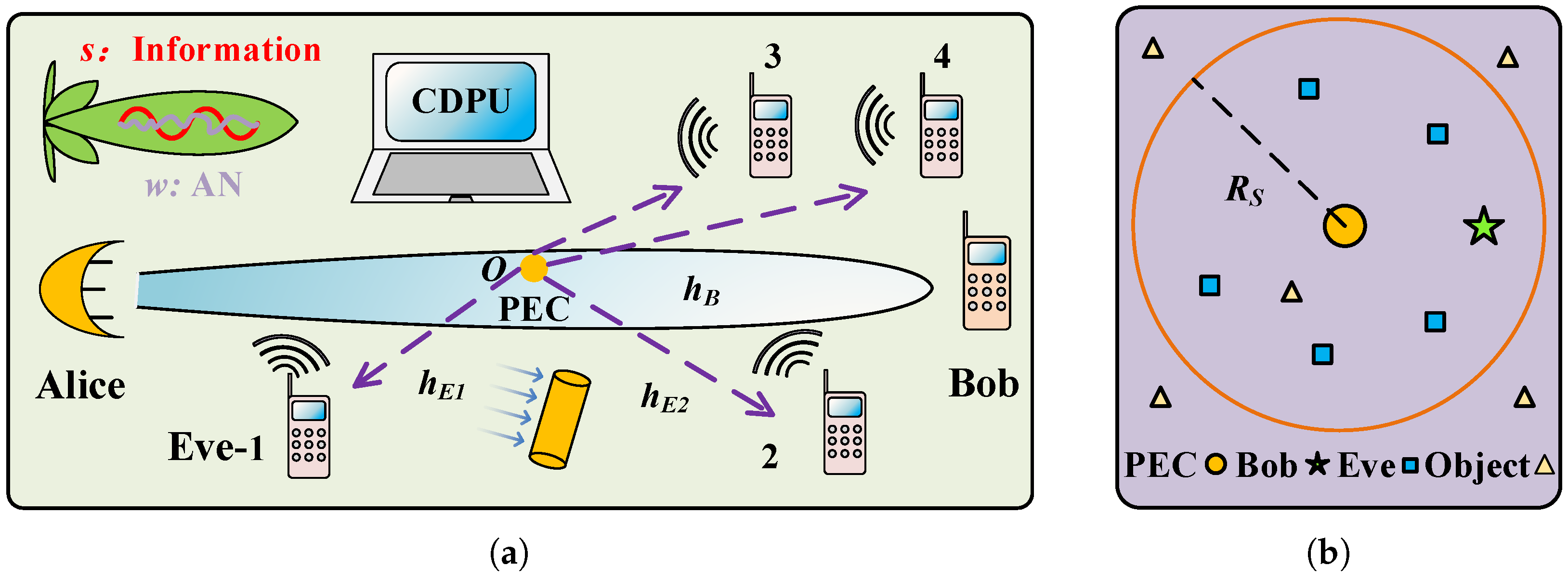
2. System Model
2.1. Signal Model
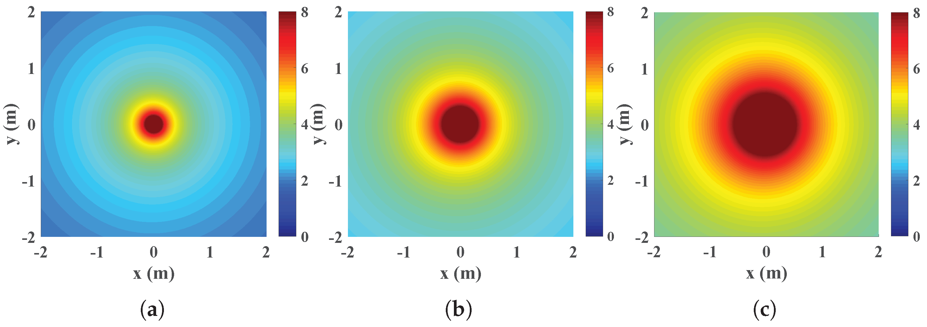
2.2. Highly Directive Channel
2.3. Scatter Channel
3. Secrecy Performance
3.1. Performance Metrics
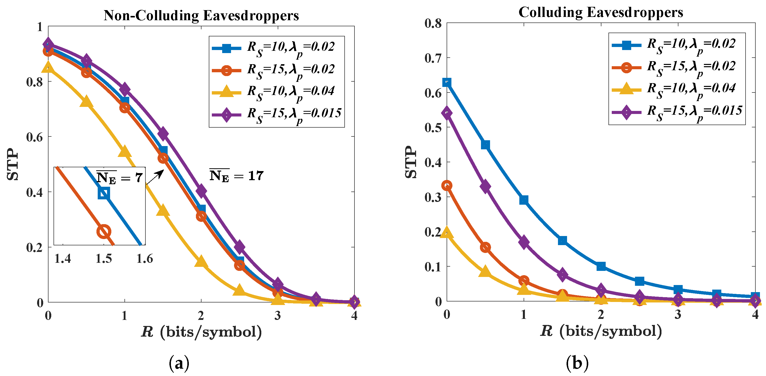
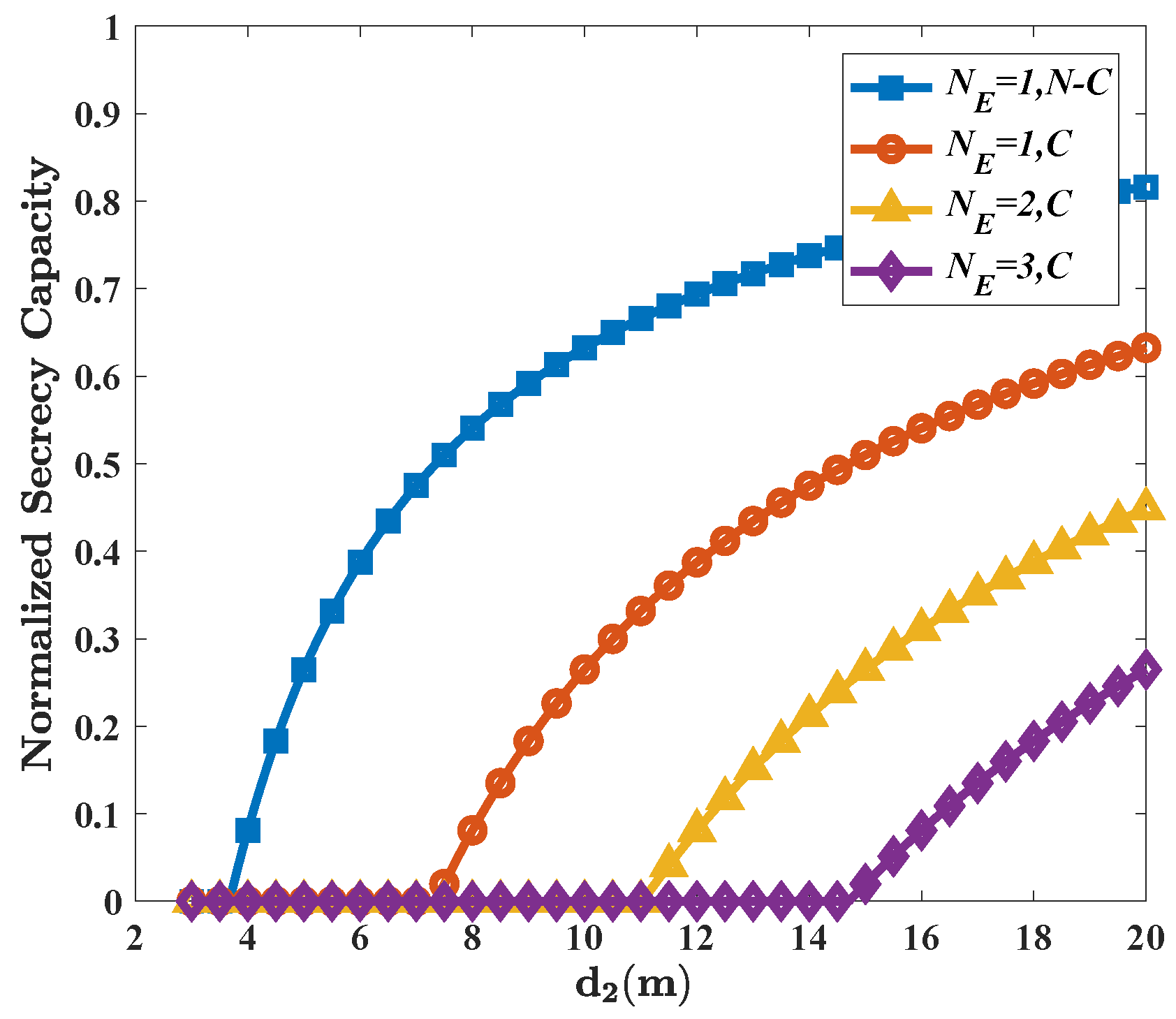
3.2. Non-Colluding Eavesdroppers
3.3. Colluding Eavesdroppers
4. Security Analysis
4.1. Eve’s Attack
4.2. AN as a Countermeasure
5. Discussion
6. Conclusions
Author Contributions
Funding
Data Availability Statement
Conflicts of Interest
Appendix A
References
- Nagatsuma, T.; Ducournau, G.; Renaud, C.C. Advances in terahertz communications accelerated by photonics. Nat. Photonics 2016, 10, 371–379. [Google Scholar] [CrossRef]
- Chen, S.; Liang, Y.C.; Sun, S.; Kang, S.; Cheng, W.; Peng, M. Vision, requirements, and technology trend of 6G: How to tackle the challenges of system coverage, capacity, user data-rate and movement speed. IEEE Wirel. Commun. 2020, 27, 218–228. [Google Scholar] [CrossRef]
- Huq, K.M.; Kazi, M.S.; Busari, S.A.; Rodriguez, J.; Frascolla, V.; Bazzi, W.; Sicker, D.C. Terahertz-enabled wireless system for beyond-5G ultra-fast networks: A brief survey. IEEE Netw. 2019, 33, 89–95. [Google Scholar] [CrossRef]
- Zhang, Z.; Xiao, Y.; Ma, Z.; Xiao, M.; Ding, Z.; Lei, X.; Karagiannidis, G.K.; Fan, P. 6G wireless networks: Vision, requirements, architecture, and key technologies. IEEE Veh. Technol. Mag. 2019, 14, 28–41. [Google Scholar] [CrossRef]
- Han, C.; Bicen, A.O.; Akyildiz, I.F. Multi-ray channel modeling and wideband characterization for wireless communications in the terahertz band. IEEE Trans. Wirel. Commun. 2015, 14, 2402–2412. [Google Scholar] [CrossRef]
- Yu, X.; Jia, S.; Hu, H.; Galil, M.; Morioka, T.; Jepsen, P.U.; Oxenløwe, L.K. 160 Gbit/s photonics wireless transmission in the 300–500 GHz band. Apl Photonics 2016, 1, 081301. [Google Scholar] [CrossRef]
- Jia, S.; Pang, X.; Ozolins, O.; Yu, X.; Hu, H.; Yu, J.; Guan, P.; Ros, F.D.; Po, S.; Jacobsen, G.; et al. 0.4 THz photonic-wireless link with 106 Gb/s single channel bitrate. J. Lightw. Technol. 2018, 36, 610–616. [Google Scholar] [CrossRef]
- Zhang, H.; Zhang, L.; Wang, S.; Lu, Z.; Yang, Z.; Liu, S.; Qiao, M.; He, Y.; Pang, X.; Zhang, X.; et al. Tbit/s multi-dimensional multiplexing THz-over-fiber for 6G wireless communication. J. Lightw. Technol. 2021, 39, 5783–5790. [Google Scholar] [CrossRef]
- Wang, S.; Lu, Z.; Li, W.; Jia, S.; Zhang, L.; Qiao, M.; Pang, X.; Idrees, N.; Saqlain, M.; Gao, X.; et al. 26.8-m THz wireless transmission of probabilistic shaping 16-QAM-OFDM signals. APL Photonics 2020, 5, 056105. [Google Scholar] [CrossRef]
- Harter, T.; Füllner, C.; Kemal, J.N.; Ummethala, S.; Steinmann, J.L.; Brosi, M.; Hesler, J.L.; Bründermann, E.; Müller, A.-S.; Freude, W.; et al. Generalized Kramers–Kronig receiver for coherent terahertz communications. Nat. Photonics 2020, 14, 601–606. [Google Scholar] [CrossRef]
- Idrees, N.M.; Lu, Z.; Saqlain, M.; Zhang, H.; Wang, S.; Zhang, L.; Yu, X. A W-Band Communication and Sensing Convergence System Enabled by Single OFDM Waveform. Micromachines 2022, 13, 312. [Google Scholar] [CrossRef]
- Yang, P.; Xiao, Y.; Xiao, M.; Li, S. 6G wireless communications: Vision and potential techniques. IEEE Netw. 2019, 33, 70–75. [Google Scholar] [CrossRef]
- Tariq, F.; Khandaker, M.R.; Wong, K.K.; Imran, M.A.; Bennis, M.; Debbah, M. A speculative study on 6G. IEEE Wirel. Commun. 2020, 27, 118–125. [Google Scholar] [CrossRef]
- Zou, Y.; Zhu, J.; Wang, X.; Hanzo, L. A survey on wireless security: Technical challenges, recent advances, and future trends. Proc. IEEE 2016, 104, 1727–1765. [Google Scholar] [CrossRef]
- Yang, N.; Wang, L.; Geraci, G.; Elkashlan, M.; Yuan, J.; Renzo, M.D. Safeguarding 5G wireless communication networks using physical layer security. Nat. Photonics 2015, 53, 20–27. [Google Scholar] [CrossRef]
- Goel, S.; Negi, R. Guaranteeing secrecy using artificial noise. IEEE Trans. Wirel. Commun. 2008, 7, 2180–2189. [Google Scholar] [CrossRef]
- Li, B.; Zhang, M.; Rong, Y.; Han, Z. Artificial Noise-Aided Secure Relay Communication With Unknown Channel Knowledge of Eavesdropper. IEEE Trans. Wirel. Commun. 2021, 20, 3168–3179. [Google Scholar] [CrossRef]
- Yang, F.; Zhang, K.; Zhai, Y.; Quan, J.; Dong, Y. Artificial Noise Design in Time Domain for Indoor SISO DCO-OFDM VLC Wiretap Systems. J. Lightw. Technol. 2021, 39, 6450–6458. [Google Scholar] [CrossRef]
- Xu, W.; Li, B.; Tao, L.; Xiang, W. Artificial Noise Assisted Secure Transmission for Uplink of Massive MIMO Systems. IEEE Trans. Veh. Technol. 2021, 70, 6750–6762. [Google Scholar] [CrossRef]
- Ding, X.; Song, T.; Zou, Y.; Chen, X.; Hanzo, L. Security-reliability tradeoff analysis of artificial noise aided two-way opportunistic relay selection. IEEE Trans. Veh. Technol. 2017, 66, 3930–3941. [Google Scholar] [CrossRef]
- Wyner, A.D. The wire-tap channel. Bell Syst. Tech. J. 1975, 54, 1355–1387. [Google Scholar] [CrossRef]
- Gopala, P.K.; Lai, L.; Gamal, H.E. On the secrecy capacity of fading channels. IEEE Trans. Inf. Theory 2008, 10, 4687–4698. [Google Scholar] [CrossRef]
- Shafiee, S.; Liu, N.; Ulukus, S. Towards the secrecy capacity of the Gaussian MIMO wire-tap channel: The 2-2-1 channel. IEEE Trans. Inf. Theory 2009, 55, 4033–4039. [Google Scholar] [CrossRef]
- Helena, R.P.; Jordi, H.J. Computational and energy costs of cryptographic algorithms on handheld devices. Future Internet 2011, 3, 31–48. [Google Scholar]
- Jia, S.; Lo, M.-C.; Zhang, L.; Ozolins, O.; Udalcovs, A.; Kong, D.; Pang, X.; Yu, X.; Xiao, S.; Popov, S.; et al. Integrated dual-DFB laser for 408 GHz carrier generation enabling 131 Gbit/s wireless transmission over 10.7 meters. In Proceedings of the Optical Fiber Communication Conference, San Diego, CA, USA, 7 March 2019. [Google Scholar]
- Guerboukha, H.; Shrestha, R.; Neronha, J.; Ryan, O.; Hornbuckle, M.; Fang, Z.; Mittleman, D.M. Efficient leaky-wave antennas at terahertz frequencies generating highly directional beams. Appl. Phys. Lett. 2020, 117, 261103. [Google Scholar] [CrossRef]
- Qiao, J.; Alouini, M. Secure Transmission for Intelligent Reflecting Surface-Assisted mmWave and Terahertz Systems. IEEE Wirel. Commun. Lett. 2020, 9, 1743–1747. [Google Scholar] [CrossRef]
- Qiao, J.; Zhang, C.; Dong, A.; Bian, J.; Alouini, M. Securing Intelligent Reflecting Surface Assisted Terahertz Systems. IEEE Trans. Veh. Technol. 2022. accepted. [Google Scholar] [CrossRef]
- Steinmetzer, D.; Chen, J.; Classen, J.; Knightly, E.; Hollick, M. Eavesdropping with periscopes: Experimental security analysis of highly directional millimeter waves. In Proceedings of the IEEE Conference on Communications and Network Security (CNS), Florence, Italy, 28–30 September 2015. [Google Scholar]
- Ma, J.; Shrestha, R.; Adelberg, J.; Yeh, C.Y.; Hossain, Z.; Knightly, E.; Jornet, J.M.; Mittleman, D.M. Security and eavesdropping in terahertz wireless links. Nature 2018, 563, 89–93. [Google Scholar] [CrossRef]
- Ju, Y.; Wang, H.W.; Zheng, T.X.; Yin, Q.; Lee, M.H. Safeguarding millimeter wave communications against randomly located eavesdroppers. IEEE Trans. Wirel. Commun. 2018, 17, 2675–2689. [Google Scholar] [CrossRef]
- Wu, Y.; Kokkoniemi, J.; Han, C.; Juntti, M. Interference and coverage analysis for terahertz networks with indoor blockage effects and line-of-sight access point association. IEEE Trans. Wirel. Commun. 2020, 20, 1472–1486. [Google Scholar] [CrossRef]
- Pinto, P.C.; Barros, J.; Win, M.Z. Wireless physical-layer security: The case of colluding eavesdroppers. In Proceedings of the IEEE International Symposium on Information Theory, Seoul, Korea, 28 June–3 July 2009. [Google Scholar]
- Zhou, X.; Ganti, R.K.; Andrews, J.G. Secure wireless network connectivity with multi-antenna transmission. IEEE Trans. Wirel. Commun. 2011, 10, 425–430. [Google Scholar] [CrossRef]
- Zhang, X.; Zhou, X.; McKay, M.R. Enhancing secrecy with multi-antenna transmission in wireless ad hoc networks. IEEE Trans. Inf. Forensics Secur. 2013, 11, 1802–1814. [Google Scholar] [CrossRef]
- Xu, Q.; Ren, P.; Song, H.; Du, Q. Security enhancement for IoT communications exposed to eavesdroppers with uncertain locations. IEEE Access 2016, 4, 2840–2853. [Google Scholar] [CrossRef]
- Zhou, X.; McKay, M.R. Secure transmission with artificial noise over fading channels: Achievable rate and optimal power allocation. IEEE Trans. Veh. Technol. 2010, 59, 3831–3842. [Google Scholar] [CrossRef]
- Wang, H.M.; Zheng, T.; Xia, X.G. Secure MISO wiretap channels with multiantenna passive eavesdropper: Artificial noise vs. artificial fast fading. IEEE Trans. Wirel. Commun. 2015, 14, 94–106. [Google Scholar] [CrossRef]
- Zhang, X.; McKay, M.R.; Zhou, X.; Heath, R.W. Artificial-noise-aided secure multi-antenna transmission with limited feedback. IEEE Trans. Wirel. Commun. 2015, 14, 2742–2754. [Google Scholar] [CrossRef]
- Papasotiriou, E.N.; Boulogeorgos, A.A.A.; Alexiou, A. Performance analysis of THz wireless systems in the presence of antenna misalignment and phase noise. IEEE Commun. Lett. 2020, 24, 1211–1215. [Google Scholar] [CrossRef]
- Ekti, A.R.; Boyaci, A.; Alparslan, A.; Ünal, İ.; Yarkan, S.; Görçin, A.; Arslan, H.; Uysal, M. Statistical modeling of propagation channels for terahertz band. In Proceedings of the IEEE Conference on Standards for Communications and Networking (CSCN), Helsinki, Finland, 18–20 September 2017. [Google Scholar]
- Sadiku, M.N. Numerical Techniques in Electromagnetics, 2nd ed.; CRC Press: Boca Raton, FL, USA, 2000. [Google Scholar]
- Stoyan, D.; Kendall, W.; Mecke, J. Stochastic Geometry and Its Applications, 2nd ed.; John Wiley and Sons: Hoboken, NJ, USA, 1996. [Google Scholar]
- Johnson, W. The curious history of Faà di Bruno’s formula. Am. Math. Mon. 2002, 109, 217–234. [Google Scholar]
- Shrestha, R.; Guerboukha, H.; Fang, Z.; Knightly, E.; Mittleman, D.M. Jamming a terahertz wireless link. Nat. Commun. 2022, 13, 3045. [Google Scholar] [CrossRef]
- Boulogeorgos, A.A.A.; Jornet, J.; Alexiou, A. Directional terahertz communication systems for 6G: Fact check: A quantitative look. IEEE Veh. Technol. Mag. 2021, 16, 68–77. [Google Scholar] [CrossRef]


| Side | Symbol | Parameter Setting | Value |
|---|---|---|---|
| Alice | P | Transmitting power | −10 dBm |
| Antenna gain | 25/27 dBi | ||
| N | Antenna number | Independent variable | |
| Power allocation ratio | Independent variable | ||
| Channel | Covering radius | 10/15 m | |
| Density of eavesdroppers | Independent variable | ||
| Number of eavesdroppers | Independent variable | ||
| a | Radius of cylinder | Independent variable | |
| Distance between Eve and PEC | Independent variable | ||
| Distance between Alice and PEC | Independent variable | ||
| m | Nakagami fading parameters | 2 | |
| Bob | Distance between Alice and Bob | Independent variable | |
| Antenna gain | 25/27 dBi | ||
| Other | c | Speed of light | 3 × 10 m/s |
| f | Frequency | Independent variable | |
| Noise power | −75 dBm | ||
| W | Bandwidth | 50 GHz | |
| N-C | Non-colluding case | - | |
| C | Colluding case | - |
Publisher’s Note: MDPI stays neutral with regard to jurisdictional claims in published maps and institutional affiliations. |
© 2022 by the authors. Licensee MDPI, Basel, Switzerland. This article is an open access article distributed under the terms and conditions of the Creative Commons Attribution (CC BY) license (https://creativecommons.org/licenses/by/4.0/).
Share and Cite
He, Y.; Zhang, L.; Liu, S.; Zhang, H.; Yu, X. Secure Transmission of Terahertz Signals with Multiple Eavesdroppers. Micromachines 2022, 13, 1300. https://doi.org/10.3390/mi13081300
He Y, Zhang L, Liu S, Zhang H, Yu X. Secure Transmission of Terahertz Signals with Multiple Eavesdroppers. Micromachines. 2022; 13(8):1300. https://doi.org/10.3390/mi13081300
Chicago/Turabian StyleHe, Yuqian, Lu Zhang, Shanyun Liu, Hongqi Zhang, and Xianbin Yu. 2022. "Secure Transmission of Terahertz Signals with Multiple Eavesdroppers" Micromachines 13, no. 8: 1300. https://doi.org/10.3390/mi13081300