
Experimental Investigation on the Effect of Surface Shape and Orientation in Magnetic Field Assisted Mass Polishing


Abstract
:1. Introduction
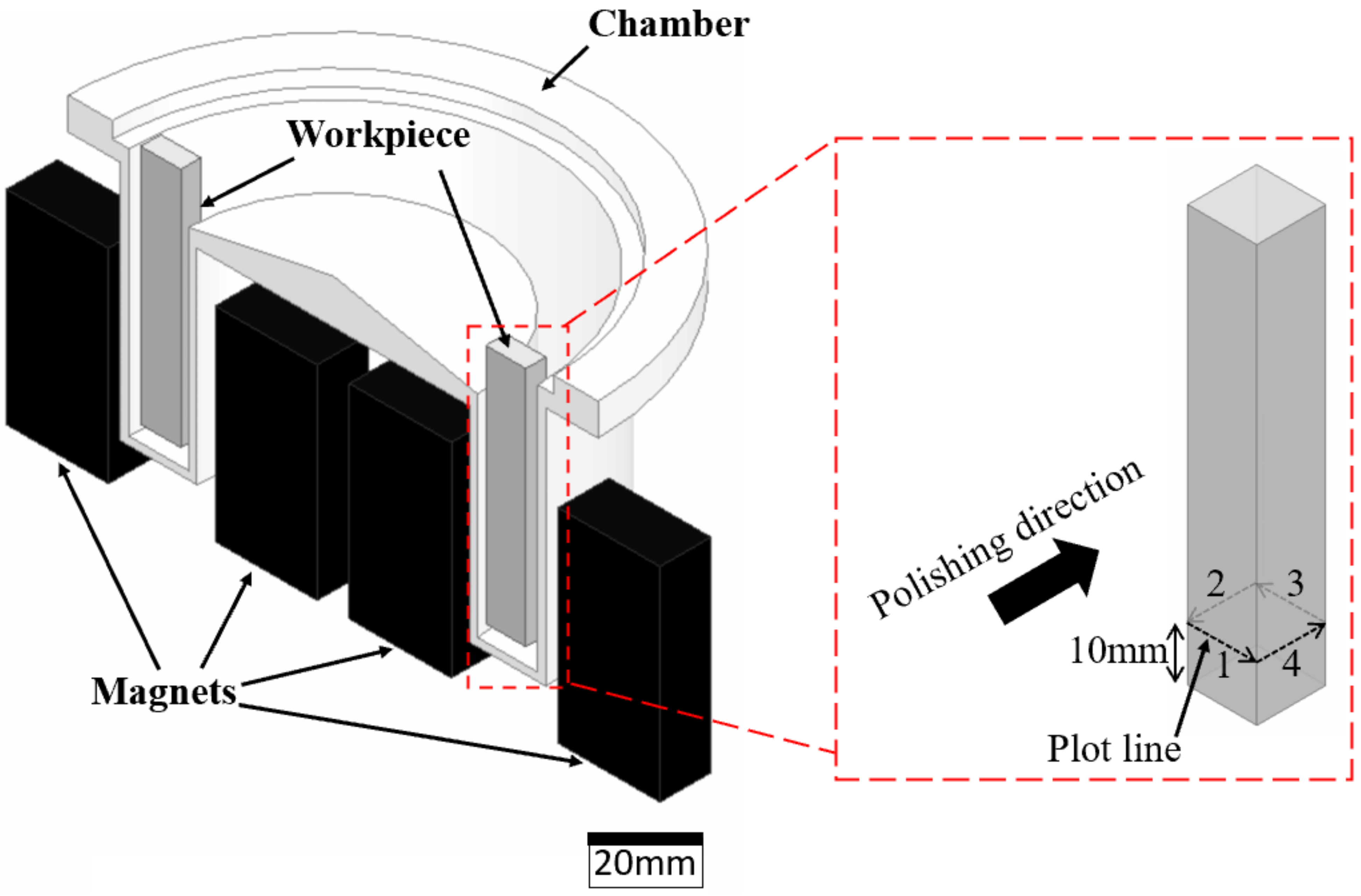
2. Experimental Procedures
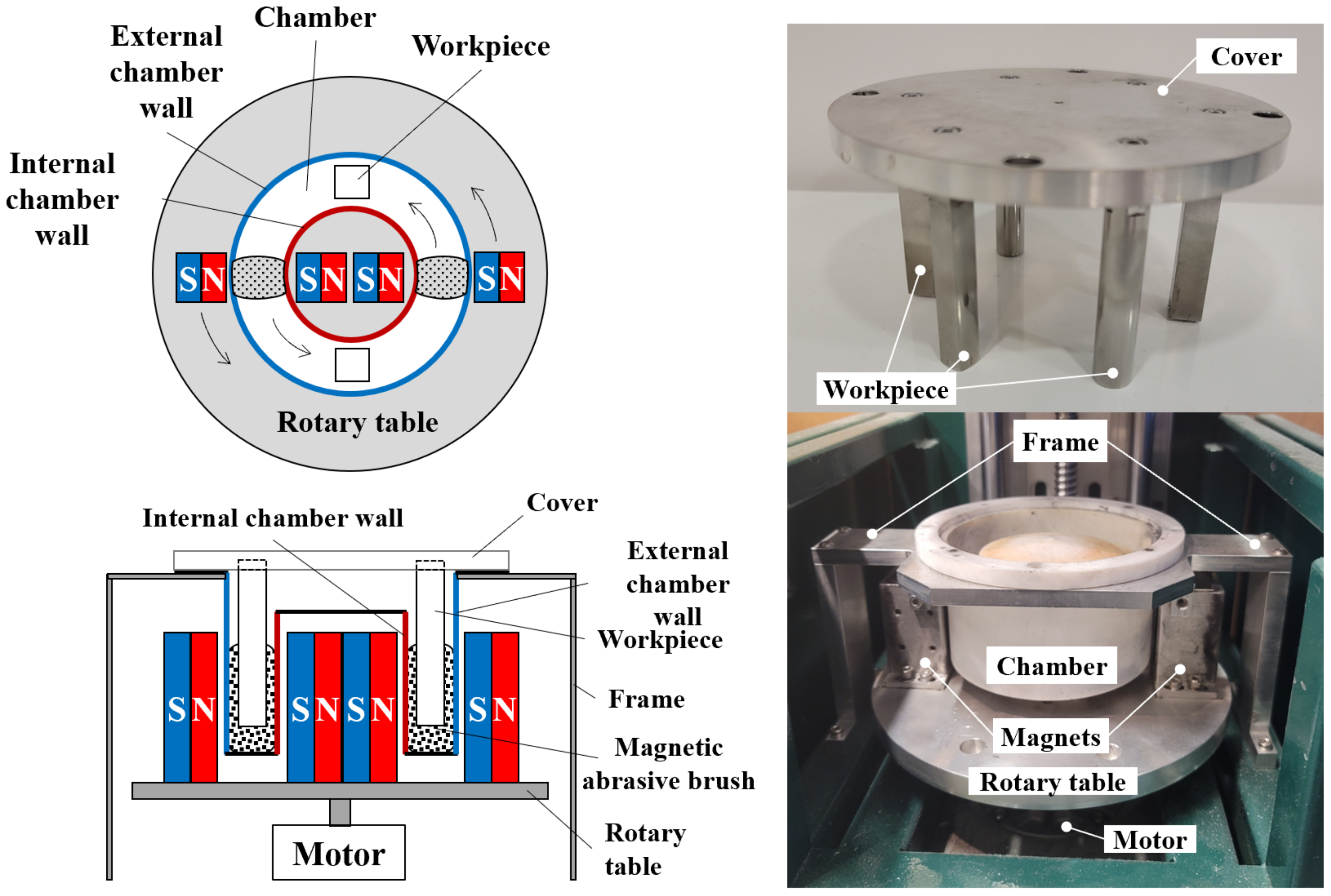
2.1. Experimental Setup
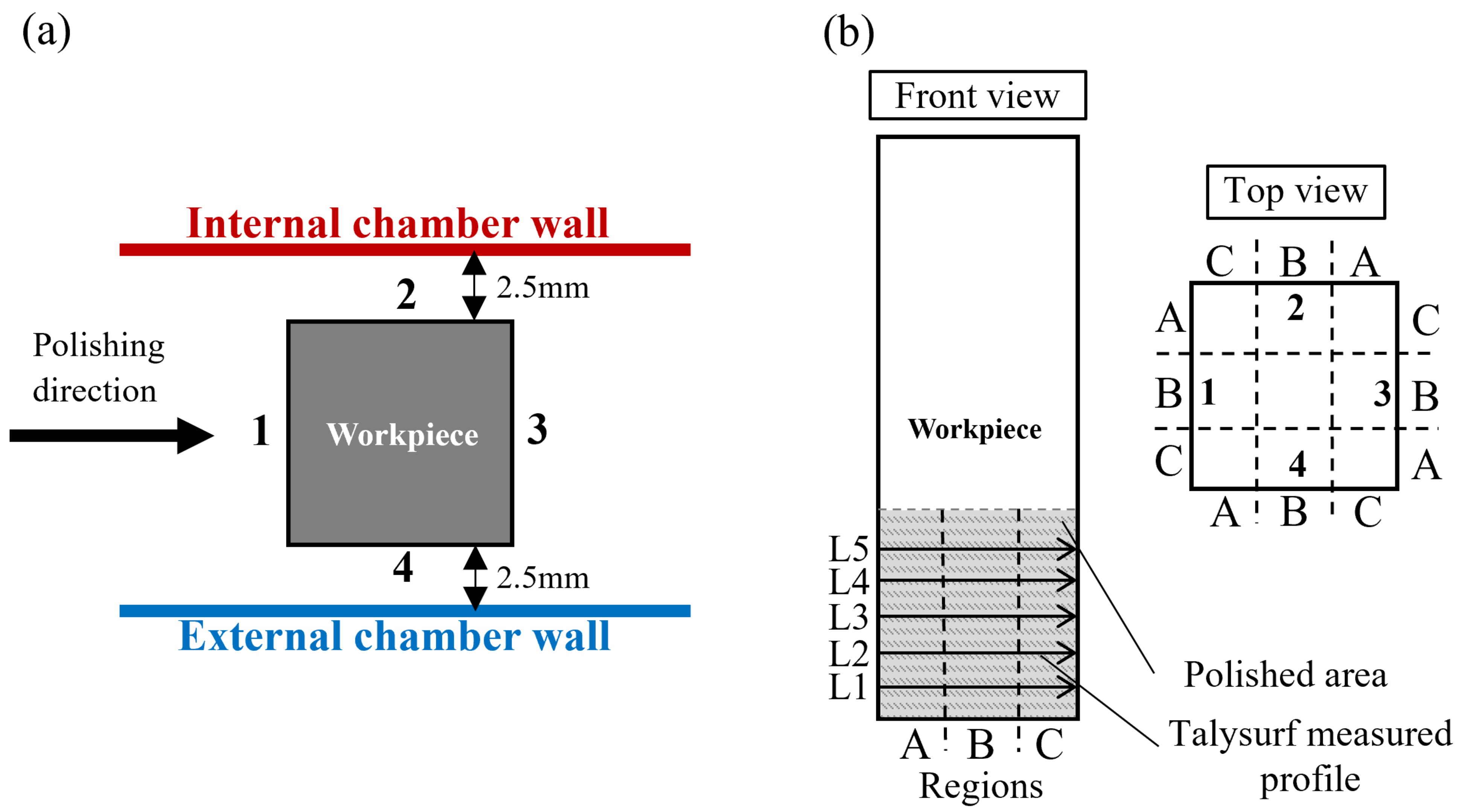
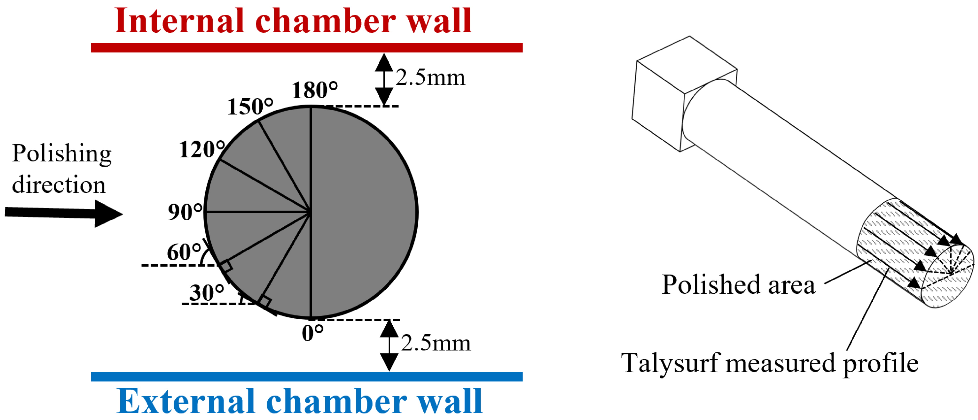
2.2. Experimental Design
3. Results
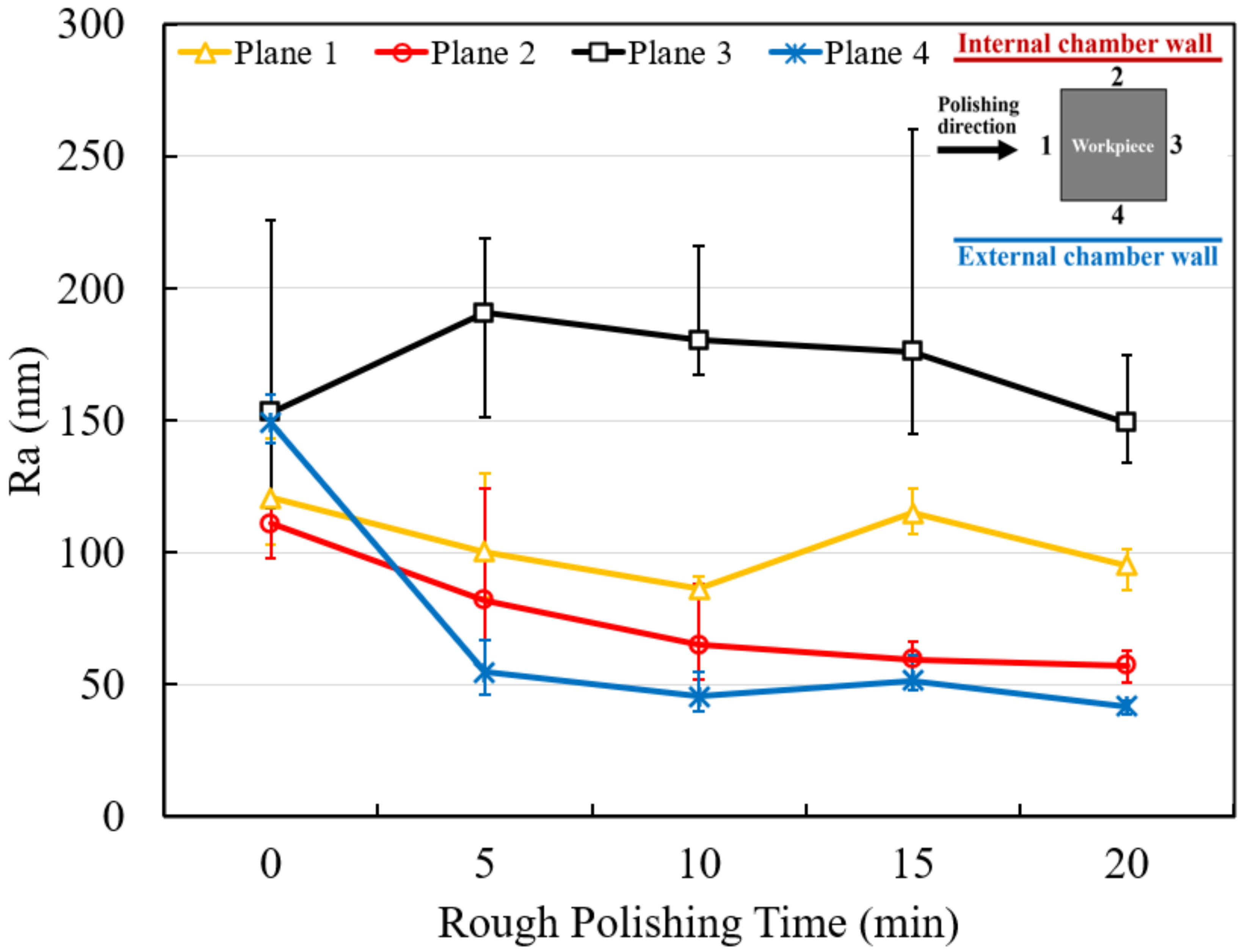
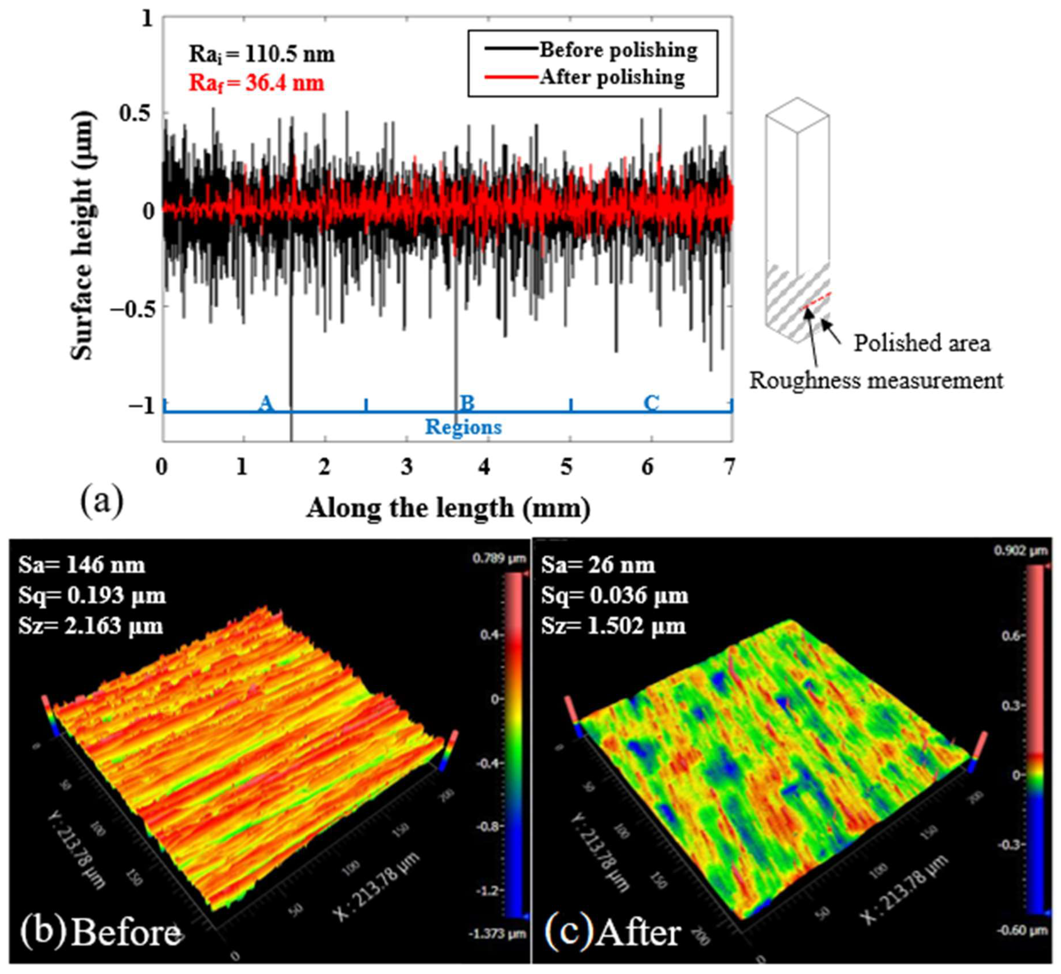
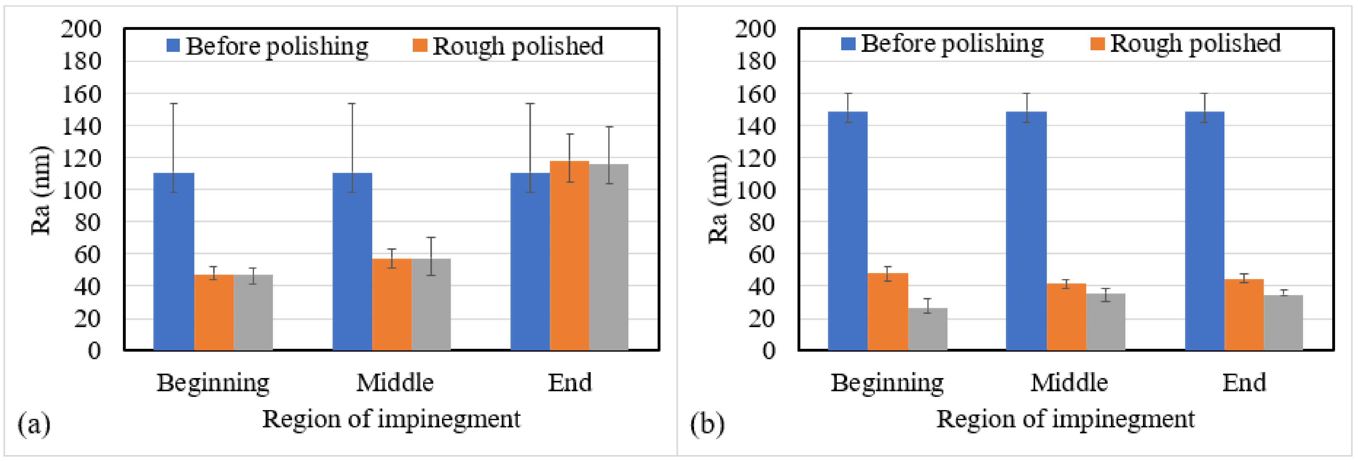
3.1. Polishing Performance in Four Different Orientations
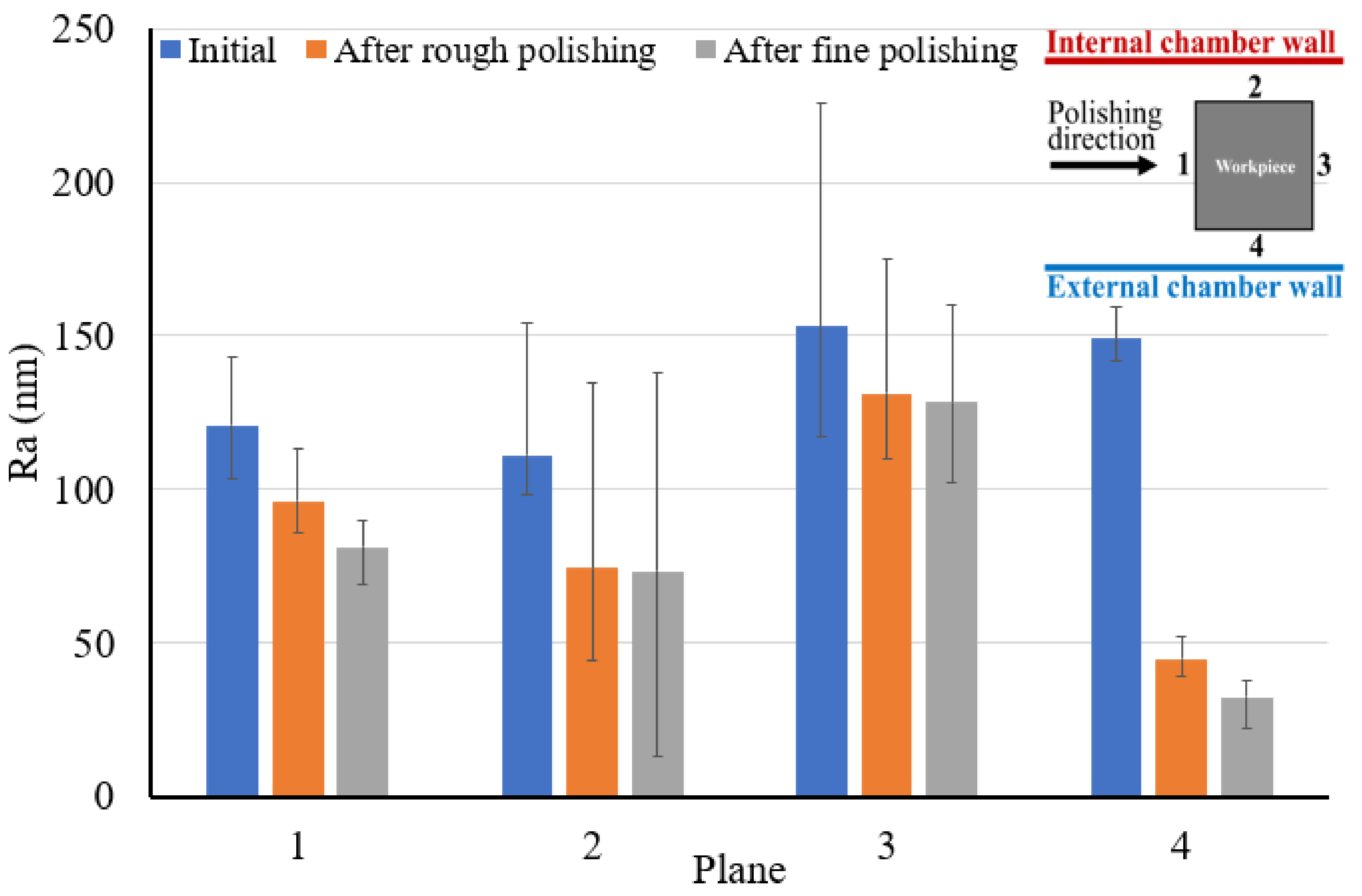
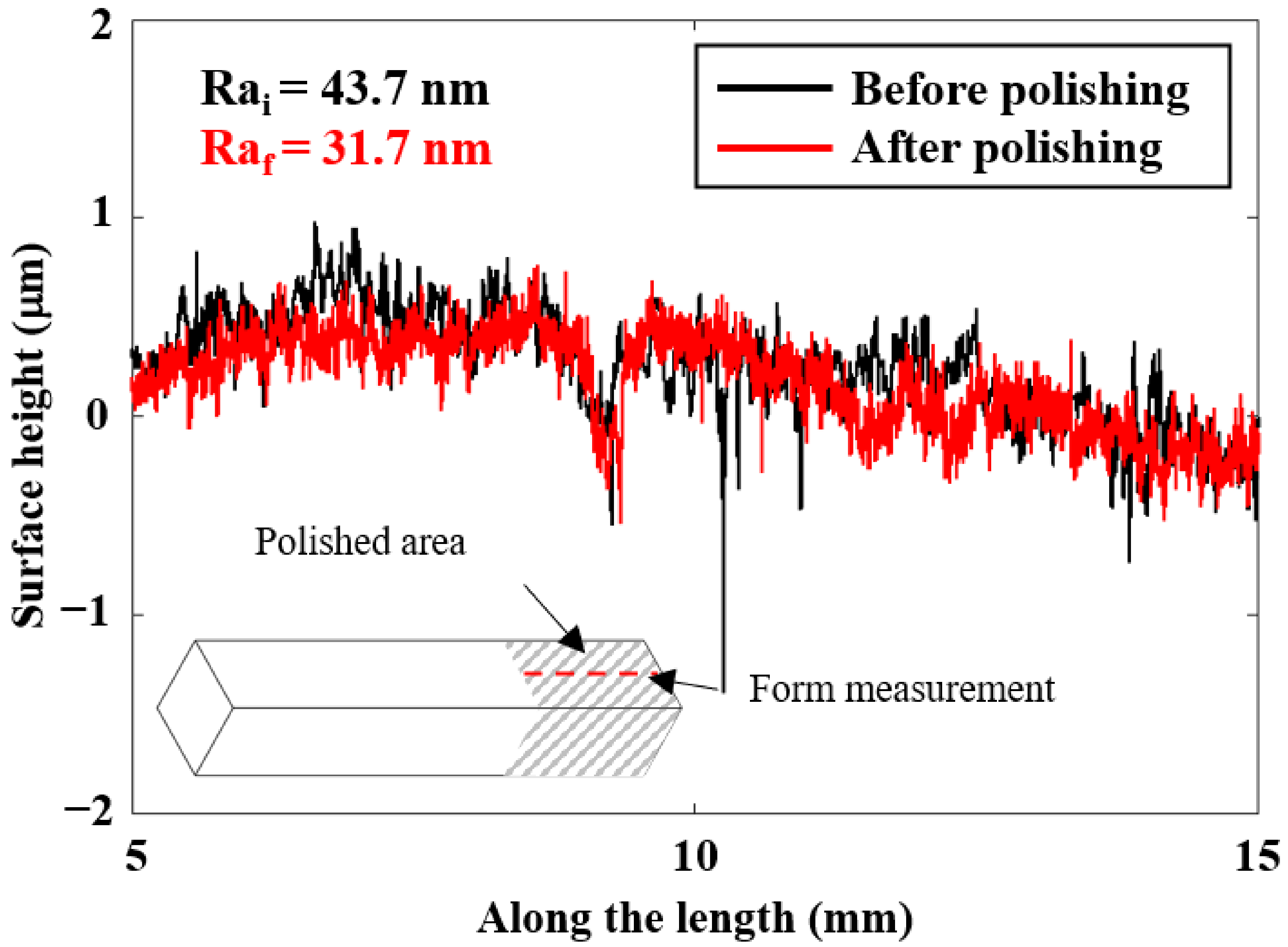
3.2. Polishing Performance on the Roller Surfaces
3.3. Simulations
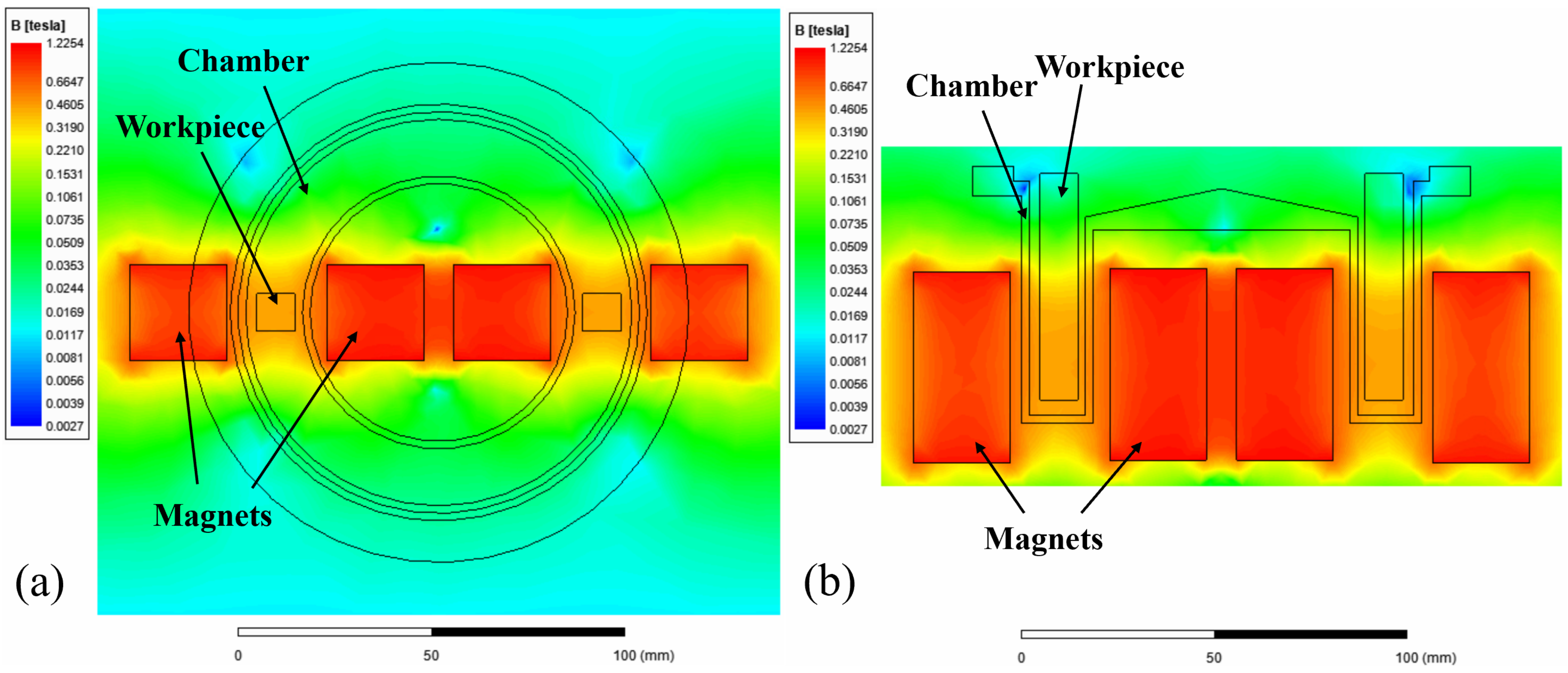
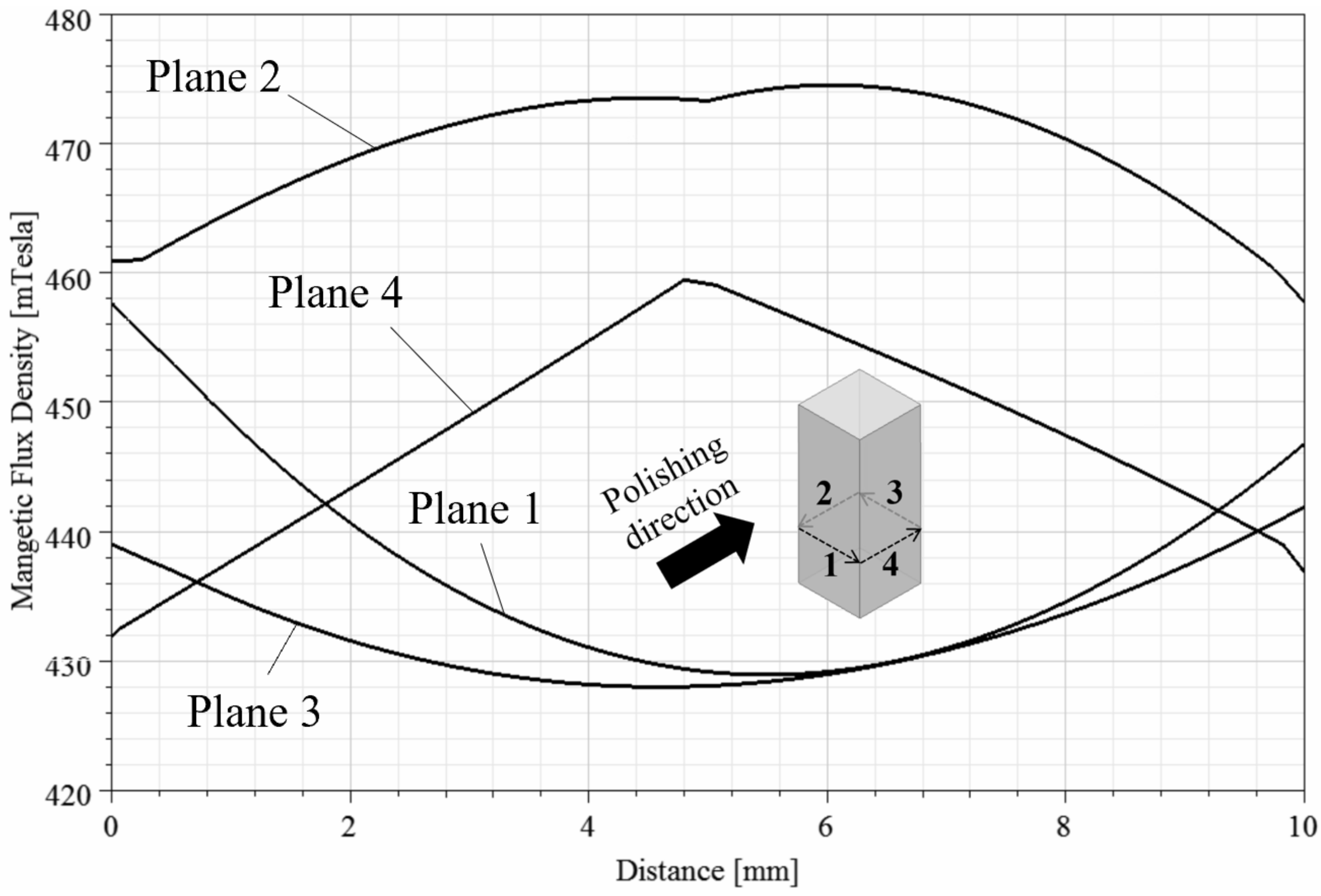
3.3.1. Simulation of the Magnetic Field Distribution
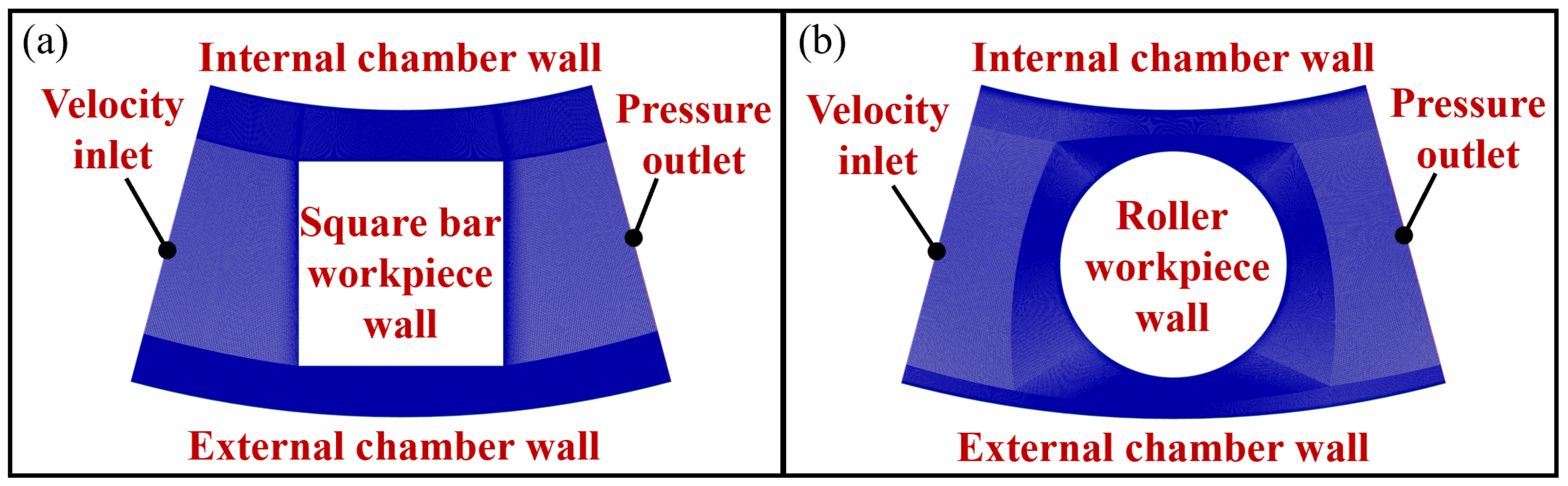
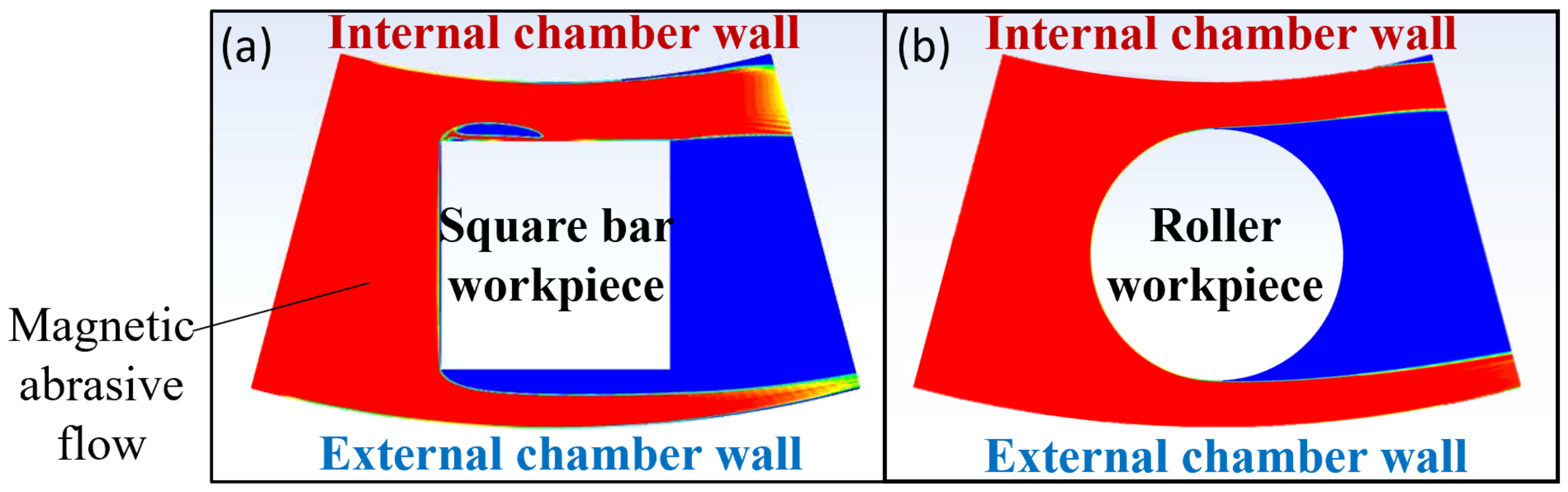
3.3.2. Simulation of Impingement
4. Discussion
4.1. Discussion on the Effect of Surface Orientation
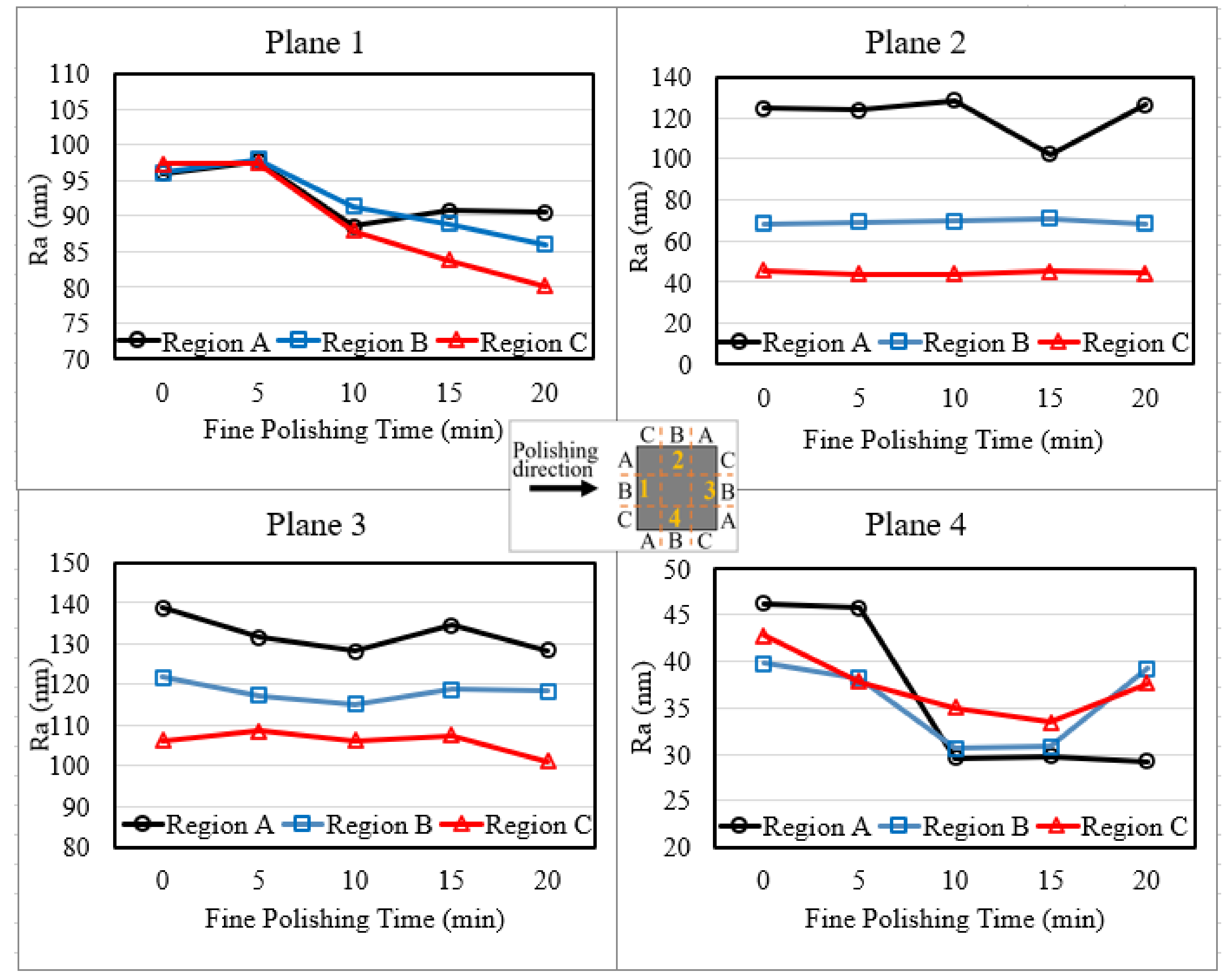
4.2. Discussion on the Effect of Different Region on the Same Surface
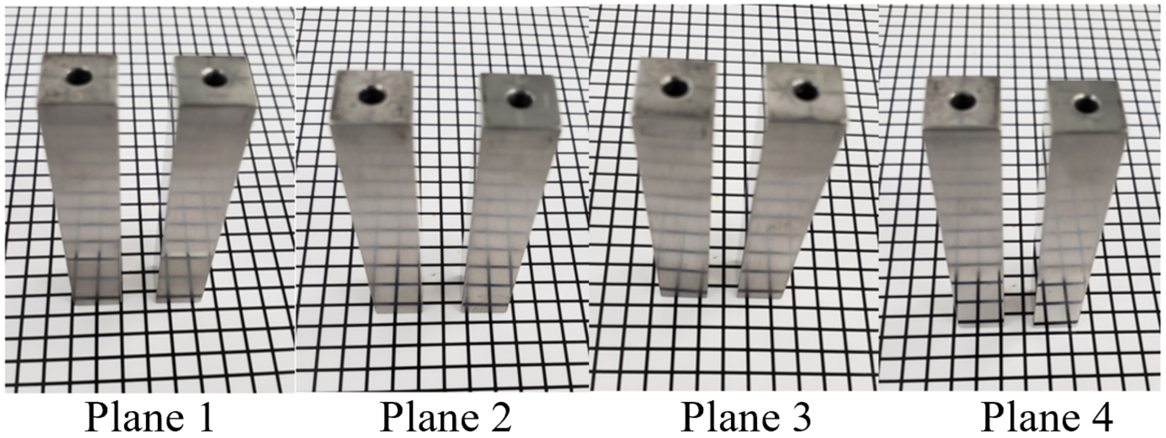
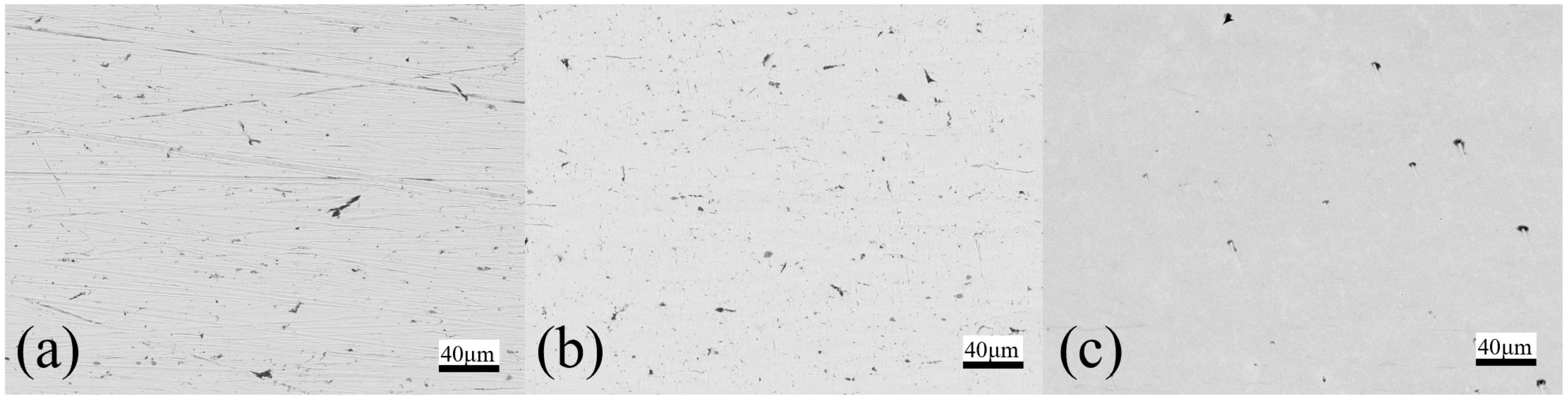
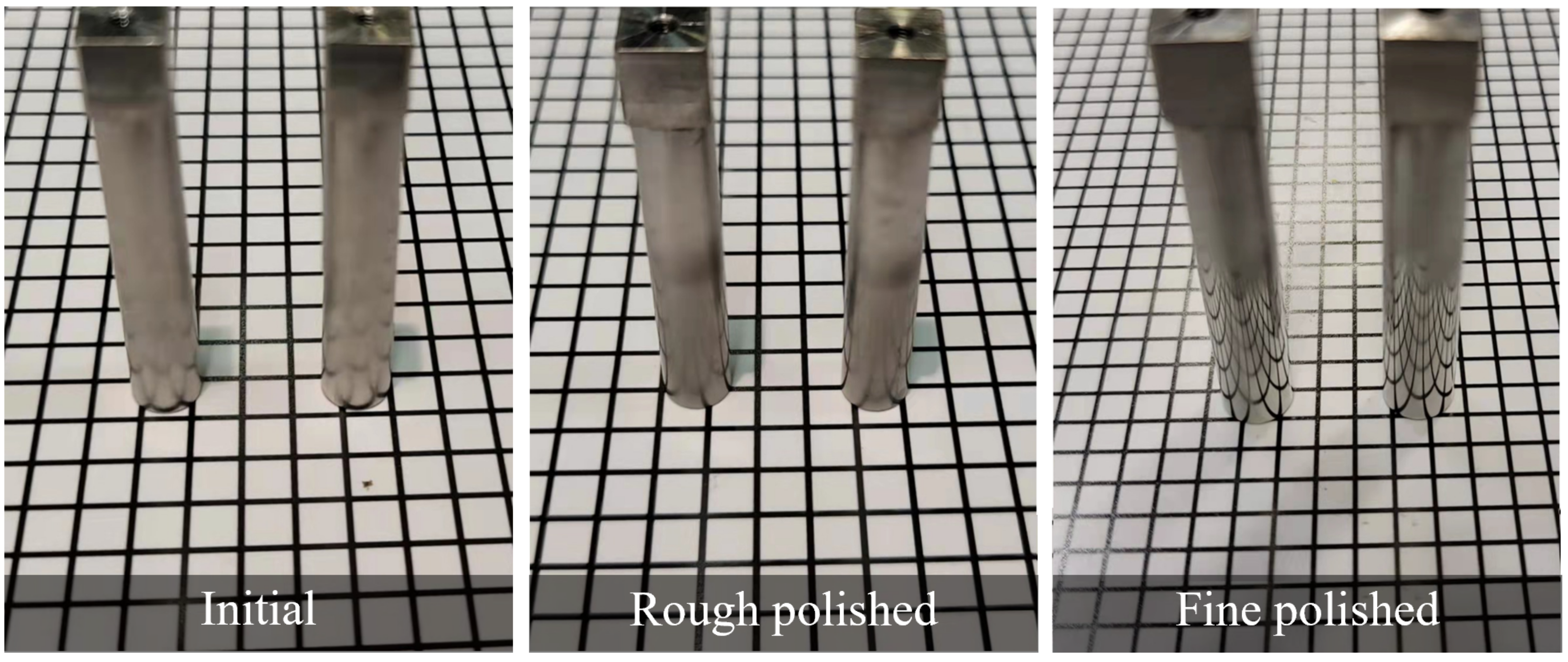
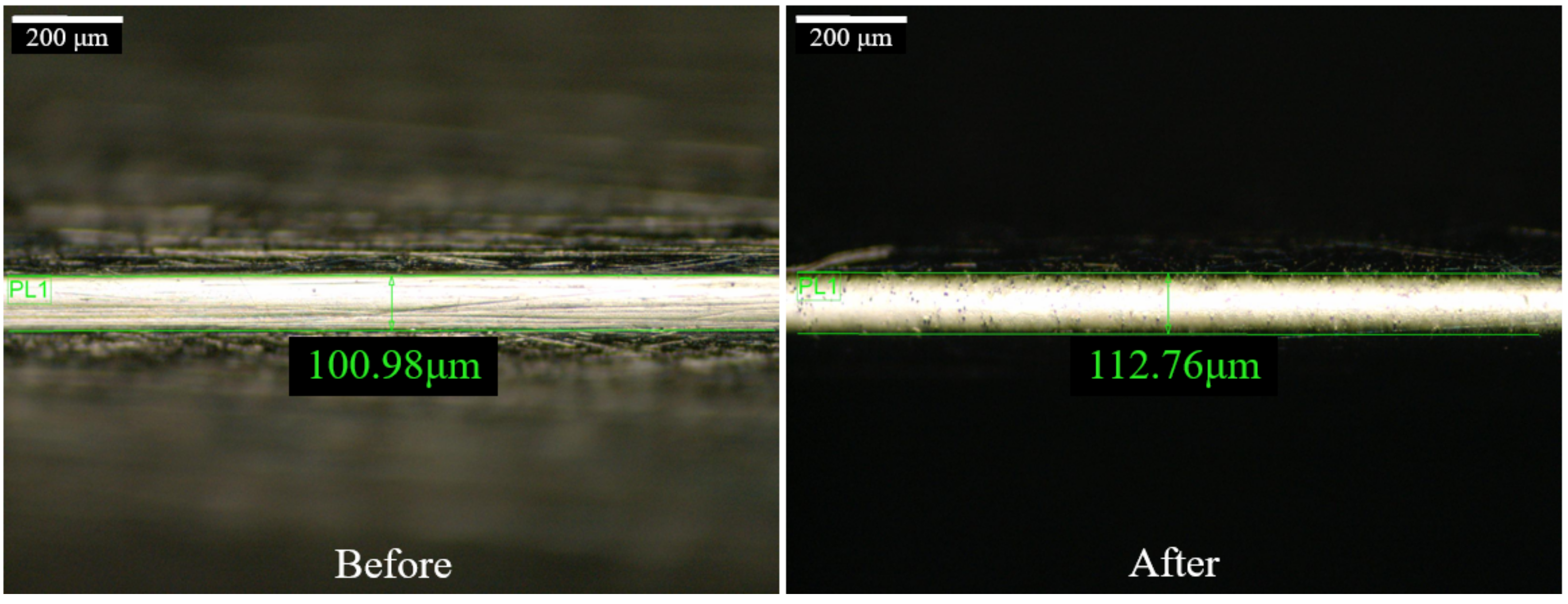
4.3. Discussion on the Edge-Rounding Effect of Square Bar Surface
4.4. Discussion on the Methods to Improve the Polishing Uniformity
5. Conclusions
- (1)
- Surfaces near the chamber wall experience higher magnetic strength, a stiffer magnetic brush is formed and thus generally performs better, and the target surface should be mounted facing outwards.
- (2)
- Regions at the beginning of impingement were polished better, as the abrasive brush was either obstructed or not conforming to the regions behind it due to the workpiece shape and high rotational speed; polishing angle adjustment will be needed to eliminate the limitations.
- (3)
- Both types of workpieces have partially achieved a final surface roughness of Ra = 20 nm after fine polishing.
- (4)
- Further investigation is still needed to study the polishing mechanism and improve the polishing uniformity.
Author Contributions
Funding
Institutional Review Board Statement
Informed Consent Statement
Conflicts of Interest
References
- Kim, D.W.; Burge, J.H.; Davis, J.M.; Martin, H.M.; Tuell, M.T.; Graves, L.R.; West, S.C. New and improved technology for manufacture of GMT primary mirror segments. In Proceedings of the SPIE Astronomical Telescopes and Instrumentation, Edinburgh, UK, 26 June–1 July 2016; SPIE: Bellingham, WA, USA, 2016; pp. 1–8. [Google Scholar]
- Fang, F.; Zhang, X.; Weckenmann, A.; Zhang, G.; Evans, C. Manufacturing and measurement of freeform optics. CIRP Ann. Manuf. Technol. 2013, 62, 823–846. [Google Scholar] [CrossRef]
- Chkhalo, N.; Kaskov, I.; Malyshev, I.; Mikhaylenko, M.; Pestov, A.; Polkovnikov, V.; Salashchenko, N.; Toropov, M.; Zabrodin, I. High-performance facility and techniques for high-precision machining of optical components by ion beams. Precis. Eng. 2017, 48, 338–346. [Google Scholar] [CrossRef]
- Wang, C.; Wang, Z.; Wang, Q.; Ke, X.; Zhong, B.; Guo, Y.; Xu, Q. Improved semirigid bonnet tool for high-efficiency polishing on large aspheric optics. Int. J. Adv. Manuf. Technol. 2016, 88, 1607–1617. [Google Scholar] [CrossRef]
- Wang, C.; Cheung, C.; Liu, M. Numerical modeling and experimentation of three dimensional material removal characteristics in fluid jet polishing. Int. J. Mech. Sci. 2017, 133, 568–577. [Google Scholar] [CrossRef]
- Yunata, E.E.; Aizawa, T.; Tamaoki, K.; Kasugi, M. Plasma Polishing and Finishing of CVD-Diamond Coated WC (Co) Dies for Dry Stamping. Procedia Eng. 2017, 207, 2197–2202. [Google Scholar] [CrossRef]
- Yamaguchi, H.; Shinmura, T.; Sato, T.; Taniguchi, A.; Tomura, T. Study of Surface Finishing Process using Magneto-rheological Fluid (MRF). J. Jpn. Soc. Precis. Eng. Contrib. Pap. 2006, 72, 100–105. [Google Scholar] [CrossRef] [Green Version]
- Hashimoto, F.; Yamaguchi, H.; Krajnik, P.; Wegener, K.; Chaudhari, R.; Hoffmeister, H.-W.; Kuster, F. Abrasive fine-finishing technology. CIRP Ann.-Manuf. Technol. 2016, 65, 597–620. [Google Scholar] [CrossRef]
- Yamaguchi, H.; Shinmura, T.; Kaneko, T. Development of a new internal finishing process applying magnetic abrasive finishing by use of pole rotation system. Int. J. Jpn. 1996, 30, 317–322. [Google Scholar]
- Yamaguchi, H.; Shinmura, T. Study of an internal magnetic abrasive finishing using a pole rotation system: Discussion of the characteristic abrasive behavior. Precis. Eng. 2000, 24, 237–244. [Google Scholar] [CrossRef]
- Vahdati, M.; Rasouli, S.A. Study of magnetic abrasive finishing on freeform surface. Int. J. Surf. Eng. Coat. 2016, 94, 294–302. [Google Scholar] [CrossRef]
- Guo, J.; Liu, K.; Wang, Z.F.; Tnay, G.L. Magnetic field-assisted finishing of a mold insert with curved microstructures for injection molding of microfluidic chips. Tribol. Int. 2017, 114, 306–314. [Google Scholar] [CrossRef]
- Yang, S.; Li, W. Surface Quality and Finishing Technology, in Surface Finishing Theory and New Technology; Springer: Berlin/Heidelberg, Germany, 2017; pp. 1–64. [Google Scholar]
- Guo, J.; Feng, W.; Jong, H.J.H.; Suzuki, H.; Kang, R. Finishing of rectangular microfeatures by localized vibration-assisted magnetic abrasive polishing method. J. Manuf. Process. 2019, 49, 204–213. [Google Scholar] [CrossRef]
- Guo, J.; Au, K.H.; Sun, C.-N.; Goh, M.H.; Kum, C.W.; Liu, K.; Wei, J.; Suzuki, H.; Kang, R. Novel rotating-vibrating magnetic abrasive polishing method for double-layered internal surface finishing. J. Mater. Process. Technol. 2018, 264, 422–437. [Google Scholar] [CrossRef]
- Sumit, Y.; Chhikara, G. Modern magnetic abrasive Finishing process. Int. J. Enhanc. Res. Sci. Technol. Eng. 2014, 3, 460–462. [Google Scholar]
- Deepak, B.; Walia, R.S.; Suri, N.M. Effect of rotational motion on the flat work piece magnetic abrasive Finishing. Int. J. Surf. Eng. Mater. Technol. 2012, 2, 550–554. [Google Scholar]
- Amnieh, S.K.; Mosaddegh, P.; Tehrani, A.F. Study on magnetic abrasive finishing of spiral grooves inside of aluminum cylinders. Int. J. Adv. Manuf. Technol. 2017, 91, 2885–2894. [Google Scholar] [CrossRef]
- Mulik, R.S.; Pandey, P.M. Ultrasonic assisted magnetic abrasive finishing of hardened AISI 52100 steel using unbonded SiC abrasives. Int. J. Refract. Met. Hard Mater. 2011, 29, 68–77. [Google Scholar] [CrossRef]
- Sihag, N.; Kala, P.; Pandey, P.M. Analysis of Surface Finish Improvement during Ultrasonic Assisted Magnetic Abrasive Finishing on Chemically treated Tungsten Substrate. Procedia Manuf. 2017, 10, 136–146. [Google Scholar] [CrossRef]
- Singh, L.; Khangura, S.S.; Mishra, P. Performance of abrasives used in magnetically assisted finishing: A state of the art review. Int. J. Abras. Technol. 2010, 3, 215–227. [Google Scholar] [CrossRef]
- Jiang, L.Z.; Zhang, G.X.; Du, J.J.; Zhu, P.X.; Cui, T.L.; Cui, Y.T. Processing performance of Al2O3/Fe-based composite spherical magnetic abrasive particles. J. Magn. Magn. Mater. 2021, 528, 167811. [Google Scholar] [CrossRef]
- Hong, S.-W.; Yoon, J.-Y.; Kim, S.-H.; Lee, S.-K.; Kim, Y.-R.; Park, Y.-J.; Kim, G.-W.; Choi, S.-B. 3D-Printed Soft Structure of Polyurethane and Magnetorheological Fluid: A Proof-of-Concept Investigation of its Stiffness Tunability. Micromachines 2019, 10, 655. [Google Scholar] [CrossRef] [Green Version]
- Yin, X.; Guo, S.; Song, Y. Magnetorheological Fluids Actuated Haptic-Based Teleoperated Catheter Operating System. Micromachines 2018, 9, 465. [Google Scholar] [CrossRef] [Green Version]
- Jacobs, S.D.; Golini, D.; Hsu, Y.L.; Puchebner, B.E.; Strafford, D.; Prokhorov, I.V.; Fess, E.M.; Pietrowski, D.; Kordonski, W.I. Magnetorheological finishing: A deterministic process for optics manufacturing. In Proceedings of the International Conference on Optical Fabrication and Testing, Tokyo, Japan, 5–7 June 1995; SPIE: Bellingham, WA, USA, 1995. [Google Scholar]
- Harris, D.C. History of magnetorheological finishing. In Proceedings of the Window and Dome Technologies and Materials XII, Orlando, FL, USA, 25–29 April 2011; Volume 8016. [Google Scholar]
- Kordonski, W.; Shorey, A.B.; Sekeres, A. New magnetically assisted finishing method: Material removal with magnetorheological fluid jet. In Proceedings of the International Conference on Optical Manufacturing and Testing V, San Diego, CA, USA, 22 December 2003. [Google Scholar]
- Pattanaik, L.N.; Agarwal, H. Magnetorheological Finishing (MRF) of a Freeform Non-magnetic Work Material. J. Manuf. Sci. Prod. 2015, 15, 249–256. [Google Scholar] [CrossRef]
- Kumar, S.; Jain, V.K.; Sidpara, A. Nanofinishing of freeform surfaces (knee joint implant) by rotational-magnetorheological abrasive flow finishing (R-MRAFF) process. Precis. Eng. 2015, 42, 165–178. [Google Scholar] [CrossRef]
- Saraswathamma, K.; Jha, S.; Rao, P. Experimental investigation into Ball end Magnetorheological Finishing of silicon. Precis. Eng. 2015, 42, 218–223. [Google Scholar] [CrossRef]
- Kansal, H.; Singh, A.K.; Grover, V. Magnetorheological nano-finishing of diamagnetic material using permanent magnets tool. Precis. Eng. 2018, 51, 30–39. [Google Scholar] [CrossRef]
- Anwesa, B.; Manas, D. Design and fabrication of a novel polishing tool for finishing freeform surfaces in magnetic field assisted finishing (MFAF) process. Precis. Eng. 2017, 49, 61–68. [Google Scholar]
- Song, W.; Peng, Z.; Li, P.; Shi, P.; Choi, S.-B. Annular Surface Micromachining of Titanium Tubes Using a Magnetorheological Polishing Technique. Micromachines 2020, 11, 314. [Google Scholar] [CrossRef] [Green Version]
- Wang, R.; Xiu, S.; Sun, C.; Li, S.; Kong, X. Study on Material Removal Model by Reciprocating Magnetorheological Polishing. Micromachines 2021, 12, 413. [Google Scholar] [CrossRef]
- Xiao, X.-L.; Li, G.-X.; Mei, H.-J.; Yan, Q.-S.; Lin, H.-T.; Zhang, F.-L. Polishing of Silicon Nitride Ceramic Balls by Clustered Magnetorheological Finish. Micromachines 2020, 11, 304. [Google Scholar] [CrossRef] [Green Version]
- Guo, J.; Wang, H.; Goh, M.H.; Liu, K. Investigation on Surface Integrity of Rapidly Solidified Aluminum RSA 905 by Magnetic Field-Assisted Finishing. Micromachines 2018, 9, 146. [Google Scholar] [CrossRef] [PubMed] [Green Version]
- Wang, C.; Cheung, C.F.; Ho, L.T.; Yung, K.L.; Kong, L. A novel magnetic field-assisted mass polishing of freeform surfaces. J. Mater. Process. Technol. 2020, 279, 116552. [Google Scholar] [CrossRef]
- Wang, C.; Loh, Y.M.; Cheung, C.F.; Wang, S.; Ho, L.T.; Li, Z. Shape-adaptive magnetic field-assisted batch polishing of three-dimensional surfaces. Precis. Eng. 2022, 76, 261–283. [Google Scholar] [CrossRef]
- Wang, C.; Loh, Y.M.; Cheung, C.F.; Wang, S.; Chen, K.; Ho, L.T.; Cheng, E. Magnetic field-assisted batch superfinishing on thin-walled components. Int. J. Mech. Sci. 2022, 223, 107279. [Google Scholar] [CrossRef]
- Shinmura, T. Study on Free Form Surface Finishing by Magnetic Abrasive Finishing Process: 1st Report, Fundamental Experiments. Trans. Jpn. Soc. Mech. Eng. Ser. C 1987, 53, 202–208. [Google Scholar] [CrossRef] [Green Version]
- Shinmura, T.; Takazawa, K.; Hatano, E.; Matsunaga, M.; Matsuo, T. Study on magnetic abrasive finishing. CIRP Ann. Manuf. Technol. 1990, 39, 325–328. [Google Scholar] [CrossRef]
- Fox, M.; Agrawal, K.; Shinmura, T.; Komanduri, R. Magnetic Abrasive Finishing of Rollers. CIRP Ann. 1994, 43, 181–184. [Google Scholar] [CrossRef]
- Shukla, V.C.; Pandey, P.M. Experimental investigations into sintering of magnetic abrasive powder for ultrasonic assisted magnetic abrasive finishing process. Mater. Manuf. Process. 2016, 32, 108–114. [Google Scholar] [CrossRef]


| Parameters | Values |
|---|---|
| Rotational speed | 1500 rpm |
| Polishing abrasive | Rough polishing 500~1000 µm Al2O3 sintered magnetic abrasives Fine polishing ~2 µm CIP (80 wt.%) + 150 nm Al2O3 (20 wt.%) |
| Polishing time | 20 min |
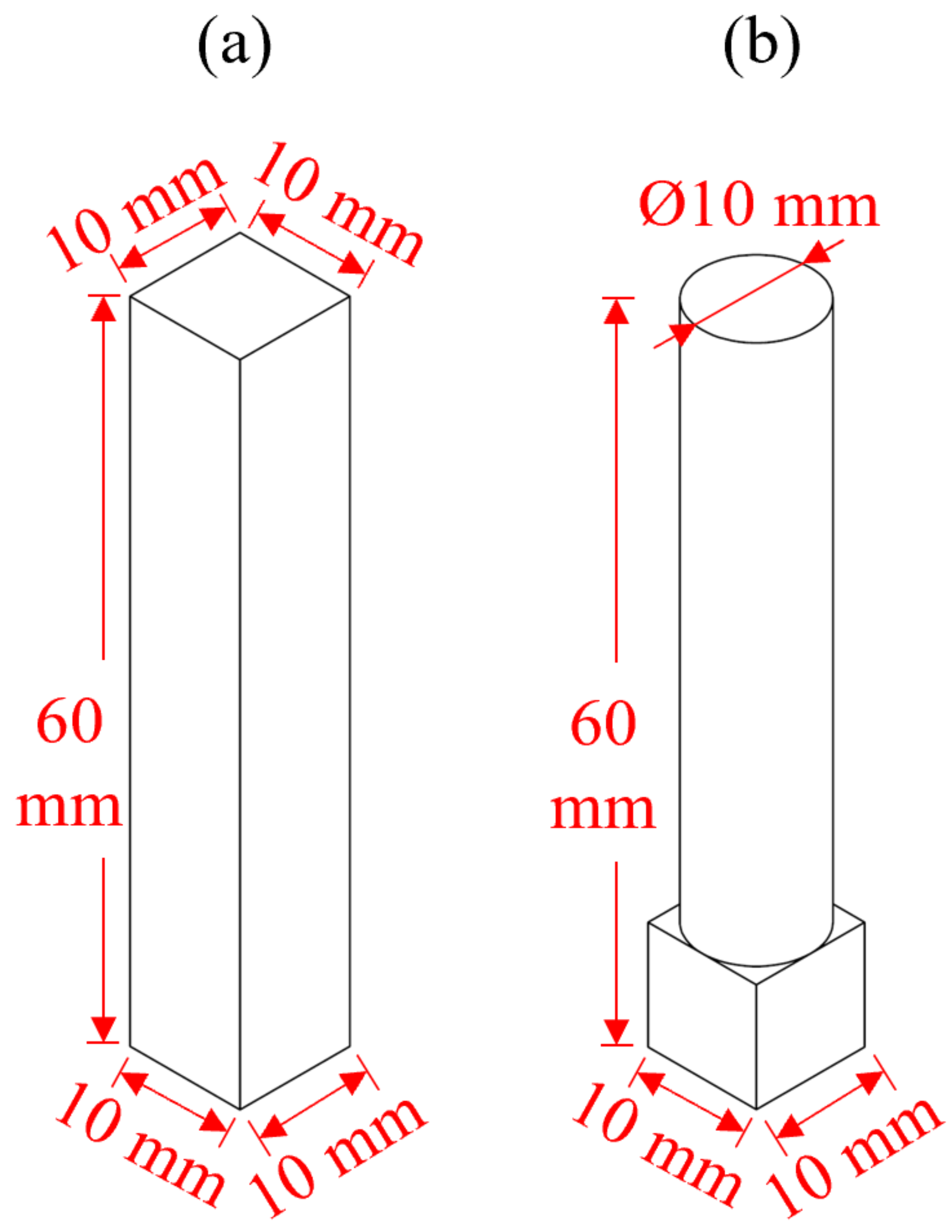
| Workpiece | Square bar (10 × 10 × 60 mm); SS304 Roller (Ø10 × 60 mm); SS304 |
| Magnets | N52 Neodymium permanent magnets, 25.4 × 25.4 × 50.8 mm; |
Publisher’s Note: MDPI stays neutral with regard to jurisdictional claims in published maps and institutional affiliations. |
© 2022 by the authors. Licensee MDPI, Basel, Switzerland. This article is an open access article distributed under the terms and conditions of the Creative Commons Attribution (CC BY) license (https://creativecommons.org/licenses/by/4.0/).
Share and Cite
Loh, Y.-M.; Cheung, C.-F.; Wang, C.; Ho, L.-T. Experimental Investigation on the Effect of Surface Shape and Orientation in Magnetic Field Assisted Mass Polishing. Micromachines 2022, 13, 1060. https://doi.org/10.3390/mi13071060
Loh Y-M, Cheung C-F, Wang C, Ho L-T. Experimental Investigation on the Effect of Surface Shape and Orientation in Magnetic Field Assisted Mass Polishing. Micromachines. 2022; 13(7):1060. https://doi.org/10.3390/mi13071060
Chicago/Turabian StyleLoh, Yee-Man, Chi-Fai Cheung, Chunjin Wang, and Lai-Ting Ho. 2022. "Experimental Investigation on the Effect of Surface Shape and Orientation in Magnetic Field Assisted Mass Polishing" Micromachines 13, no. 7: 1060. https://doi.org/10.3390/mi13071060