Article

Compact Wideband Four-Port MIMO Antenna for Sub-6 GHz and Internet of Things Applications

1
Wireless Communication Center, School of Electrical Engineering, Faculty of Engineering, Universiti Teknologi Malaysia, Johor Bahru 81310, Malaysia
2
Advanced Cyclotron Systems Inc. (ACSI), Richmond, BC V6X 1X5, Canada
3
Faculty of Engineering and Technology, Multimedia University, Melaka 75450, Malaysia
4
Department of Electrical Engineering, Faculty of Engineering, Islamic University of Madinah, P.O. Box 170, Madinah 41411, Saudi Arabia
*
Author to whom correspondence should be addressed.
Micromachines 2022, 13(12), 2202; https://doi.org/10.3390/mi13122202
Submission received: 11 October 2022 / Revised: 24 November 2022 / Accepted: 24 November 2022 / Published: 12 December 2022
(This article belongs to the Special Issue Broadband Terahertz Devices and Communication Technologies)

Abstract

:
A compact four-port multi-input, multi-output (MIMO) antenna with good isolation is proposed for sub-6 GHz and Internet of Things (IoT) applications. Four similar L-shaped antennae are placed orthogonally at 7.6 mm distance from the corner of the FR4 substrate. The wideband characteristics and the required frequency band are achieved through the L-shaped structure and with proper placement of the slots on the substrate. To obtain good isolation between the ports, rectangular slots are etched in the bottom layer and are interconnected. The proposed antenna has total dimensions of 40 mm × 40 mm × 1.6 mm. The interconnected ground plane provides good isolation of less than −17 dB between the ports, and the impedance bandwidth obtained by the proposed four-port antenna is about 54% between the frequency range of 3.2 GHz to 5.6 GHz, thus providing a wideband antenna characteristic covering sub-6 GHz 5G bands (from 3.4 to 3.6 GHz and 4.8 to 5 GHz) and the WLAN band (5.2 GHz). The proposed design antenna is fabricated and tested. Good experimental results are achieved when compared with the simulation results. As the proposed design is compact and low profile, this antenna could be a suitable candidate for 5G and IoT devices.

1. Introduction

With a large number of users and the rapid development of wireless communication technologies, higher data rates and channel capacities are in great demand [1,2]. Multiple antennae integrating in the same portable device is seen as a hopeful solution, which could enhance communication network quality and channel capacity. Hence, multi-input, multi-output (MIMO) technology plays a key role in the 5G research hotspot. The European Commission (EC) announced that the band from 3.4 to 3.8 GHz was allocated for 5G, and similarly the Ministry of Industry and Information Technology of China has also considered 3.3–3.6 GHz and 4.8–5 GHz as the operation frequency bands of the 5G system [3]. Recently, many MIMO antenna designs for 5G sub-6 GHz were reported in the literature [4,5,6,7,8,9,10,11,12], but these antennae provide less bandwidth or higher mutual coupling. Contradictorily, the mutual coupling reduction and low envelope correlation coefficients (ECCs) between nearby antenna elements could increase the antenna size, and hence these factors play a key role in antenna design for portable devices. Hence, embedding multiple antennae inside the device in a limited space while maintaining good isolation becomes an antenna design challenge for portable devices.
Different techniques were presented in [13] to reduce the mutual coupling. In order to enhance the isolation, parasitic elements [14,15] are placed between radiating elements to create extra coupling paths. Defected ground structures [16] inhibit surface waves to reduce mutual coupling between the antenna elements by acting as band-stop filters. However, this technique decreases the total antenna efficiency. The etching of slots [17] disturbs the surface current distribution and the path length, which reduces the electromagnetic energy coupling between the ports. Neutralization lines [18] are employed for isolation enhancement by creating an extra coupling path suitable for narrow band decoupling. In [19,20] high isolation is achieved through the orthogonal polarization diversity technique using different excitation modes, while in [21] the multimode decoupling technique is employed to improve the isolation between the antenna elements. However, these designs work only for a single band or less bandwidth. In [7,9,22,23], an antenna is designed for multiple bands for sub-6 GHz applications. Good isolation is achieved using the slotted ground plane method in [24], and similarly in [25], the rectangular slot is etched in the ground plane to stop the flow of current. Moreover, the antenna designs presented were either complex in structure or larger in size and thus integration into a compact MIMO structure for portable devices could be challenging. Therefore, a unique antenna design with the features of extended bandwidth and good isolation suitable for sub-6 GHz and IoT applications needs to be investigated urgently.
In this paper, a compact four-port wideband MIMO antenna design is presented, with four antenna elements positioned near each other in a symmetric fashion with a common ground plane. Simple techniques of etching the slots are used in the top layer and the ground plane to attain the required impedance bandwidth and enhance the isolation between the ports. A peak gain lies between 2.4 to 4.9 dBi for the entire operational bandwidth and the average radiation efficiency obtained is 93%. ECC achieved is less than 0.05, which satisfies the IEEE standards [6] for MIMO antennae for portable devices. The impedance bandwidth obtained by the proposed four-port antenna is about 54%, which ranges from 3.2 GHz to 5.6 GHz, thus providing wideband antenna characteristics covering sub-6 GHz 5G bands (from 3.4 to 3.6 GHz and 4.8 to 5 GHz) and the WLAN band (5.2 GHz).

2. Antenna Design

A compact four-port MIMO antenna is designed and fabricated on a FR4 substrate with thickness (t) = 1.6 mm, loss tangent (tanδ) = 0.025, and dielectric constant (εr) = 4.4. Figure 1 illustrates the geometry of the proposed antenna, and the optimum parameters related to the proposed antenna design are listed in Table 1. A simple decoupling structure is implemented in the ground plane to obtain good isolation. CST Microwave Studio has been used for simulation purposes to design and analyze the antenna parameters. The total dimensions of the MIMO antenna are 40 mm × 40 mm (~0.59λ × 0.59λ at center frequency of 4.45 GHz). The design stages are demonstrated in the subsequent sections.

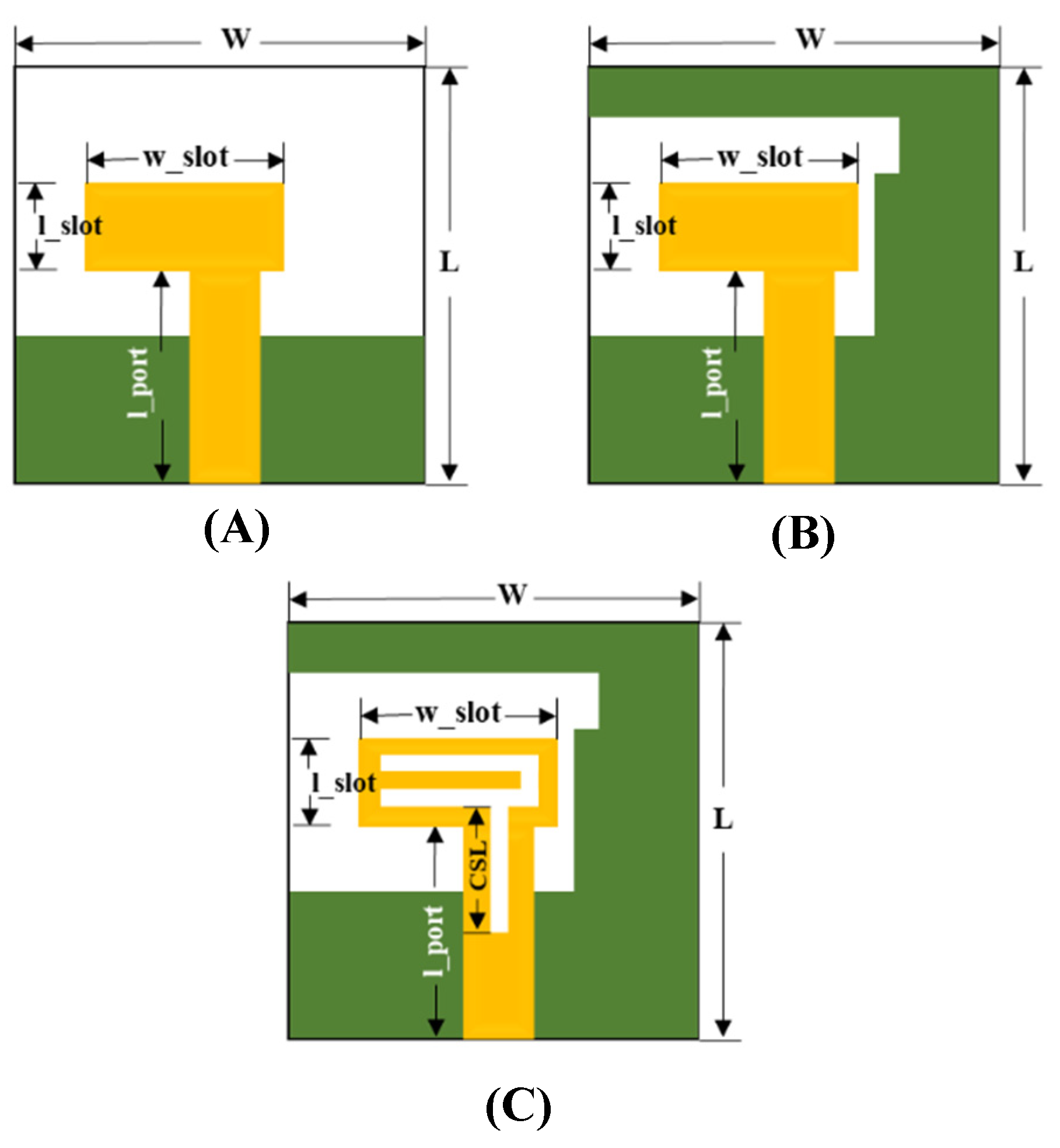
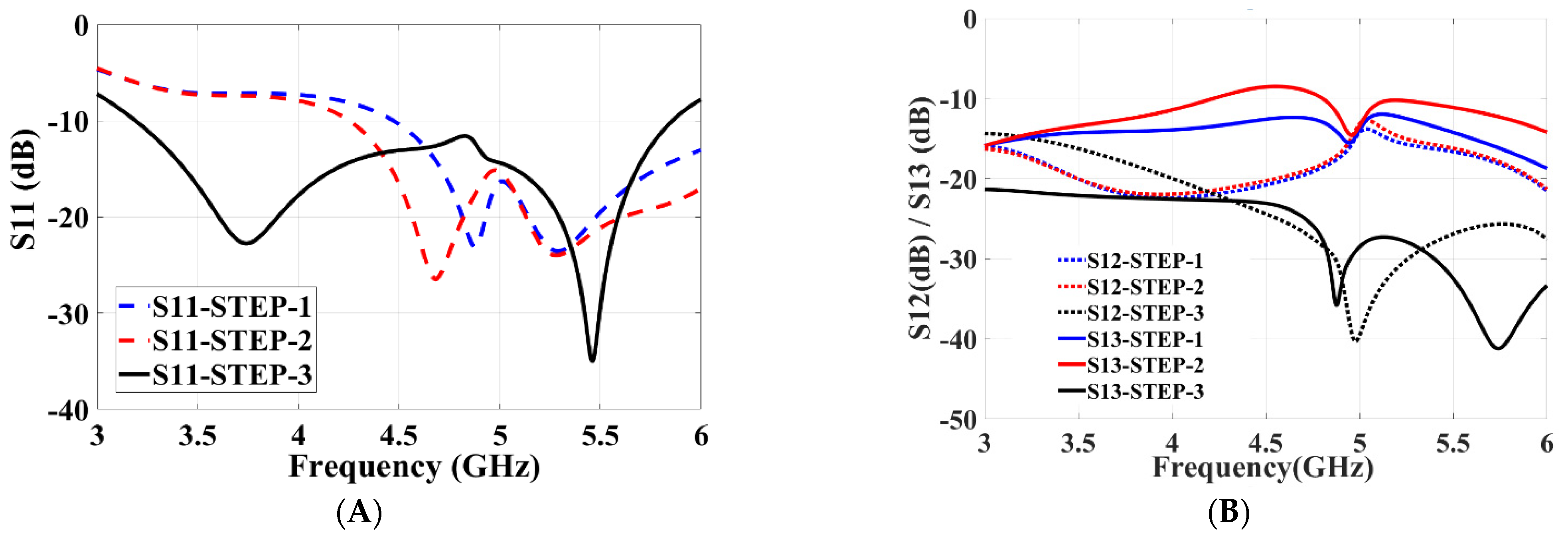
2.1. Single-Port Antenna

An initial configuration of the proposed MIMO system with a single-port antenna is shown in Figure 2C and its total dimensions is 20 mm × 20 mm × 1.6 mm. The design-evolution steps of the proposed antenna are shown in Figure 2. In Figure 3, the return-loss (S11) results obtained in each evolution step while designing the proposed MIMO antenna are shown.
Initially, an antenna with less than half ground plane and an L-shaped antenna element is designed, as shown in Figure 2A. It can be observed that the impedance bandwidth of 26% is achieved from 4.6 to 6 GHz (S11 < −10 dB). In the next steps, the ground plane is modified (Figure 2B) and then further improved (Figure 2C) to radiate for the required frequency band. The S-parameter plot in Figure 3 shows that S11 < −8 dB is achieved for the complete required frequency range from 3.5–5.4 GHz with impedance bandwidth of 43%.

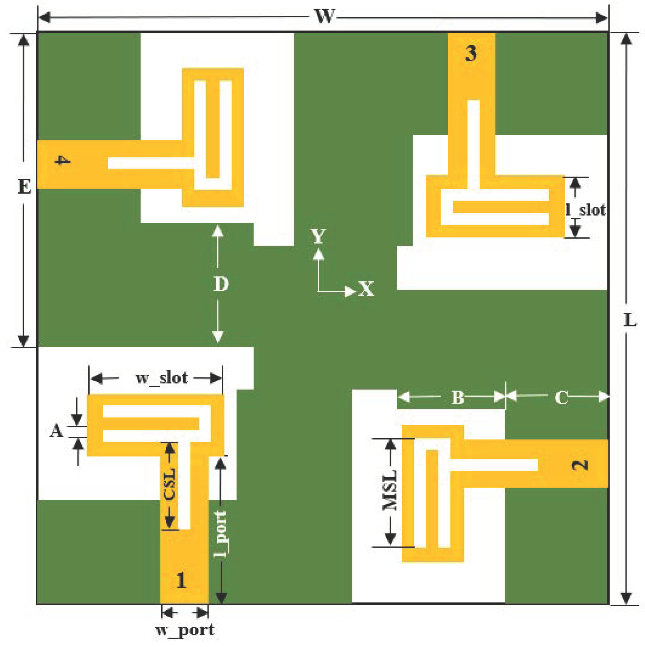
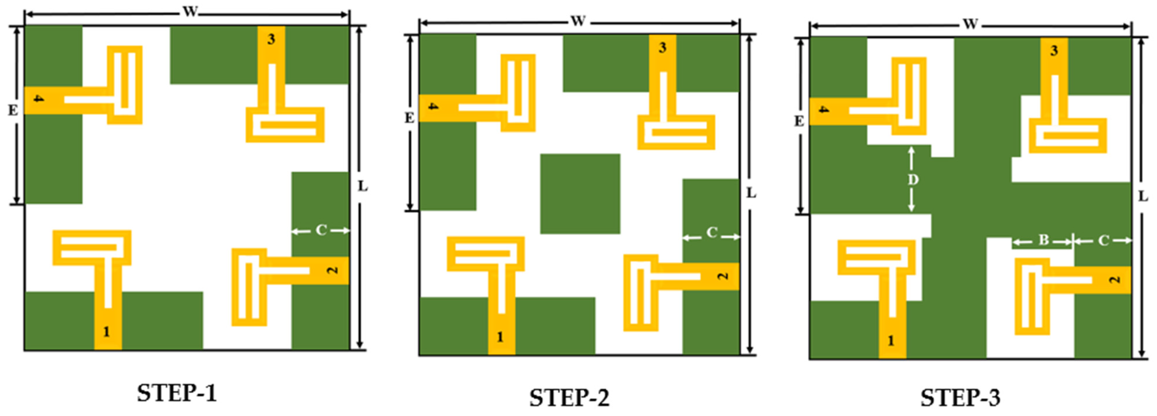
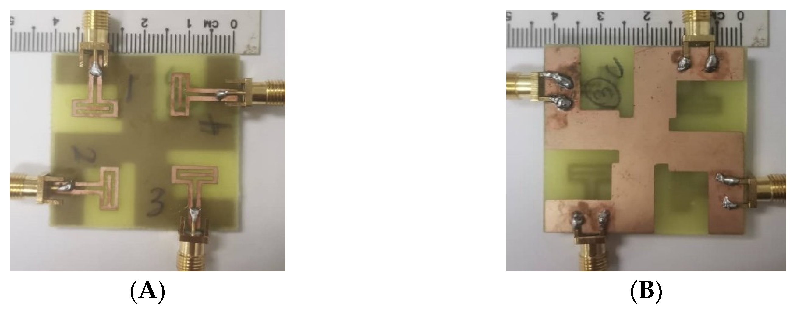
2.2. Four-Port MIMO Antenna

The four-port MIMO antenna is proposed from the single-port antenna design discussed in the preceding section. At the initial stage, four antennae are placed orthogonally to each other on the top layer of the FR4 substrate, as shown in Figure 4, and the total volume of the antenna is 40 mm × 40 mm × 1.6 mm. Each antenna element with its feeding port of width (w_port) = 3 mm is placed at a distance of 7.6 mm from the corner end of the substrate. The inter-element spacing between the two antenna elements is 12 mm. The dimensions are properly adjusted in such a way to achieve good bandwidth covering the required frequency range and to obtain good isolation.
The step-by-step configuration of the proposed antenna is shown in Figure 4. The simulated S-parameters plotted in Figure 5A clearly show that the return loss of −10 dB starts only from 4.5 GHz and from 4.2 GHz in steps 1 and 2, respectively. Similarly, both the step designs (STEP 1 and STEP 2) have high mutual coupling between the ports (Figure 5B). In order to achieve good isolation, the ground plane is modified as shown in Figure 4 (steps 2 and 3) by arranging a slot in the center of the antenna ground plane, connected to each other to form a common ground plane. It is also observed that, the currents almost penetrate between the nearby antenna elements in step 2 compared to current distribution in step 3. Good isolation and impedance bandwidth is achieved in the proposed design of step 3 (Figure 5B).

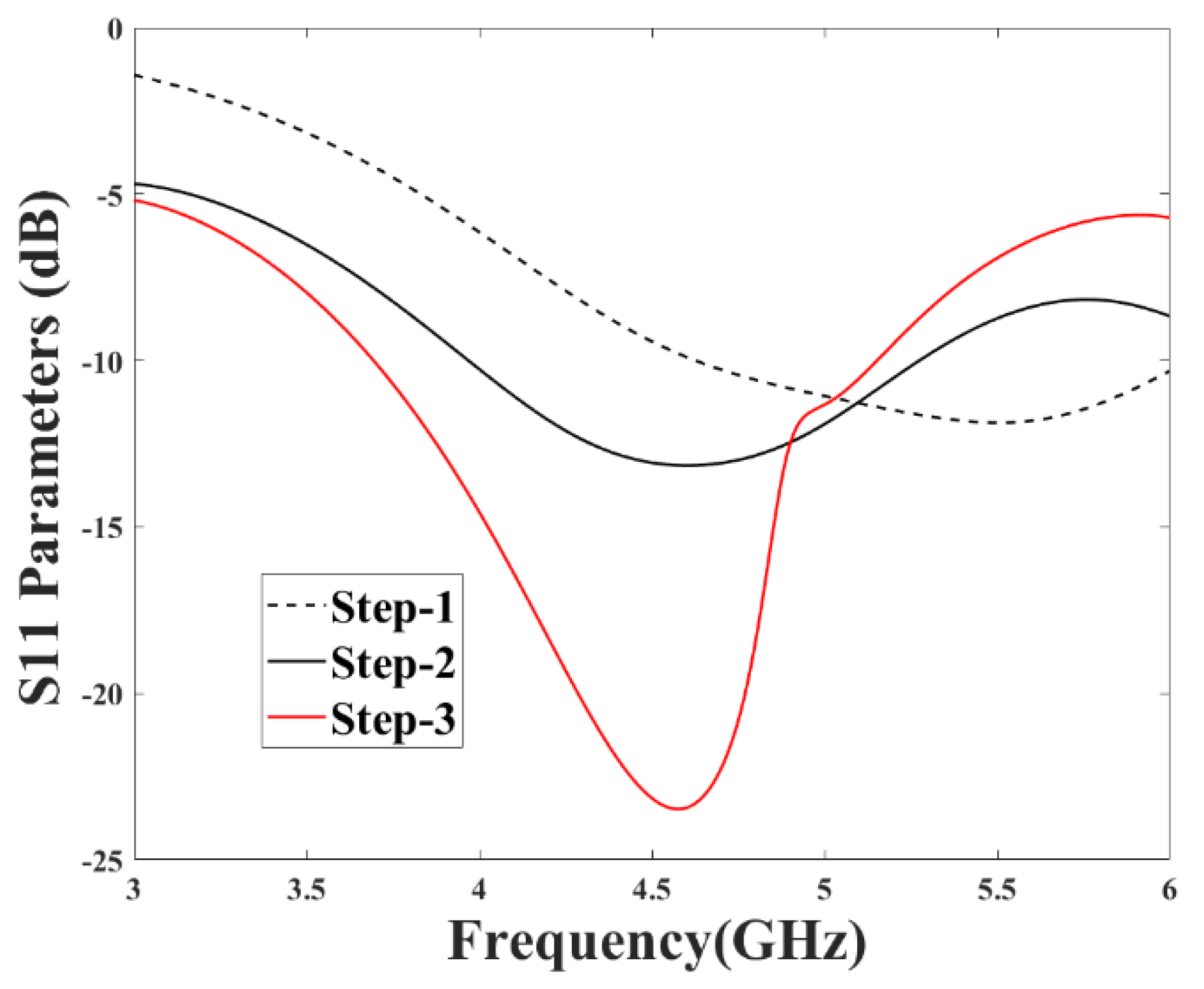
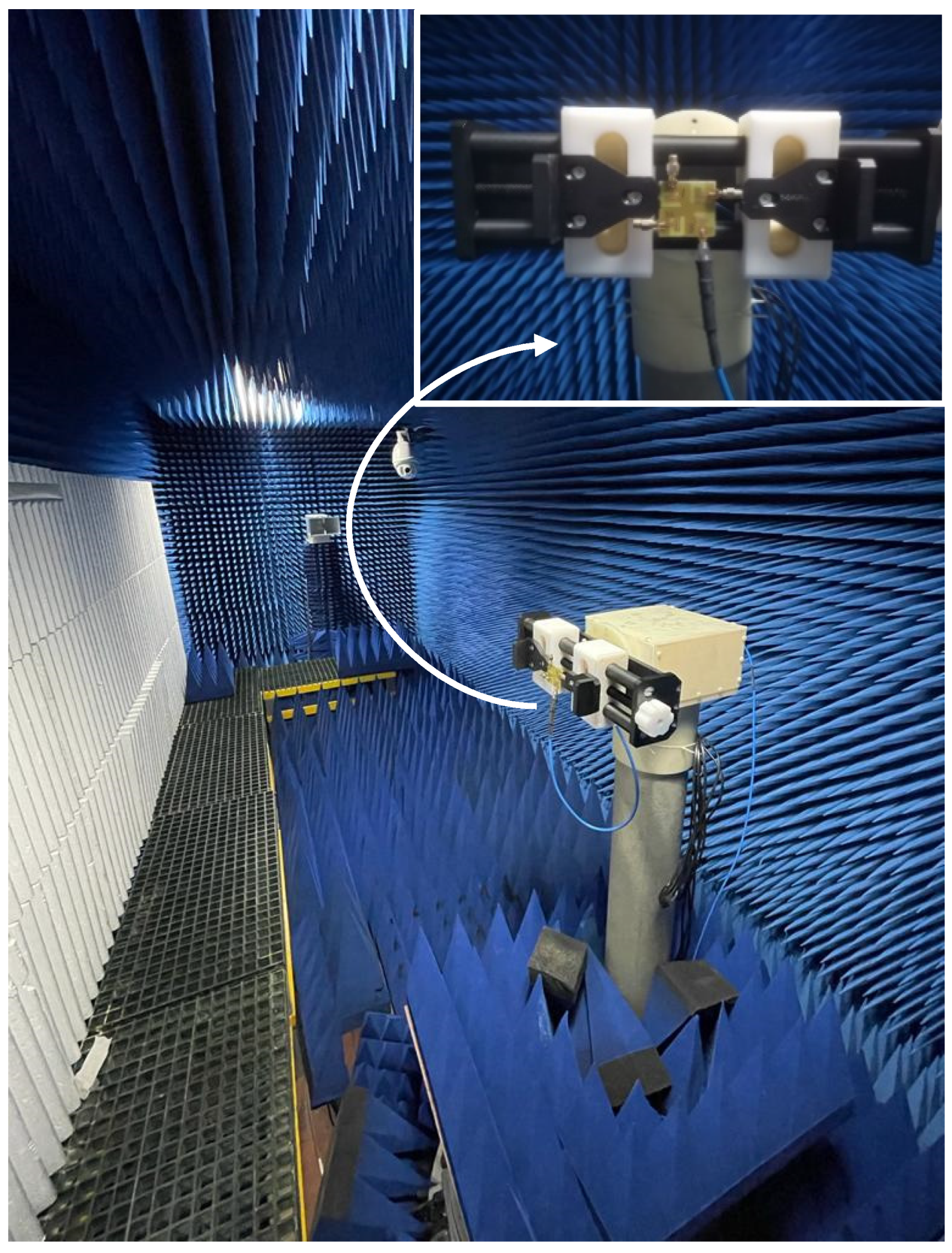
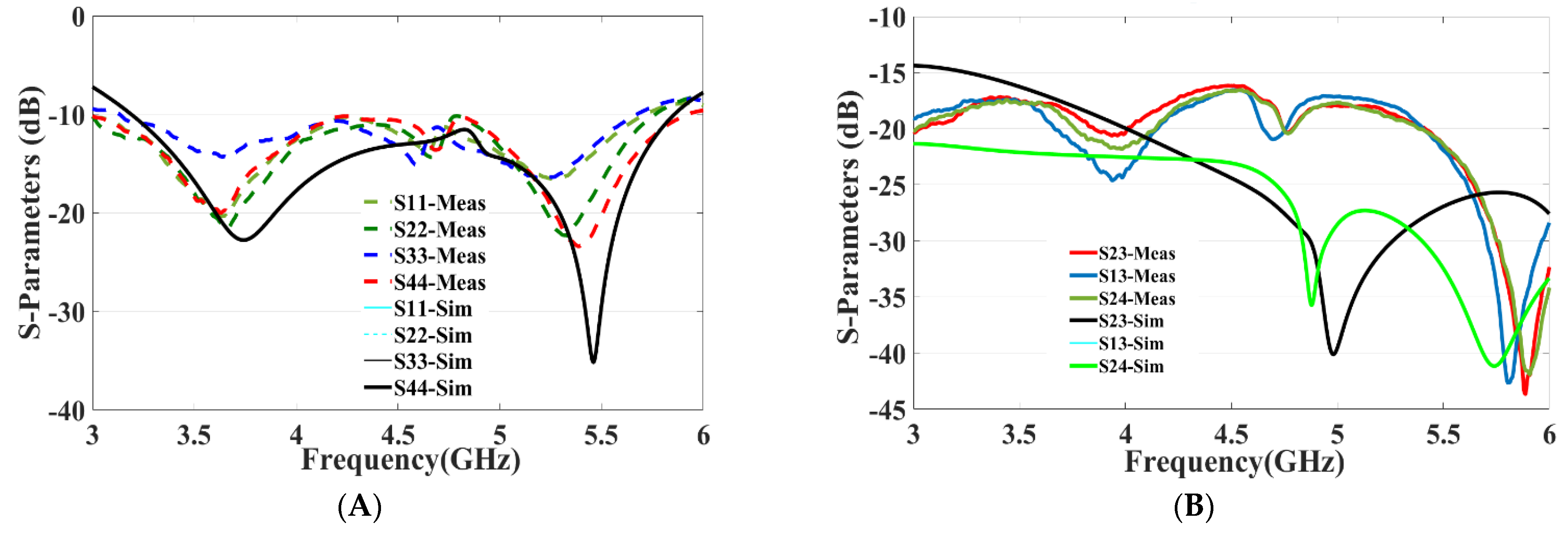
3. Results and Discussion

The fabricated four-port MIMO antenna is shown in Figure 6A (top view) and Figure 6B (bottom view). Using an Agilent PNA-X N5242A vector network analyzer (VNA), the S-parameters are measured. The radiation pattern is measured in an anechoic chamber by using a Nanjing Lopu Co. antenna measurement system. The measurement scenario of the proposed antenna is given in Figure 7 to show the measurement environment. The simulated and measured return loss for the designed antenna is represented in Figure 8A. The figure representation clearly shows that the simulated S11 results of all the four ports are the same due to its similar structure, and good impedance bandwidth of 57% is achieved between the frequency range of 3.2 GHz to 5.8 GHz.
On the other side, measured return-loss results of the proposed antenna show utmost similar results with good bandwidth of 54% covering the frequency range from 3.2 GHz to 5.6 GHz. The measured return-loss results show a slight difference in the frequency range. This difference is primarily due the fabrication process and slight alteration in the dielectric constant of the substrate.
Similarly, the simulation and measured isolation results between the antenna elements are shown in Figure 8B, and isolation between the antenna elements are greater than 16 dB throughout the expected frequency, which demonstrates that all the four antenna elements work independently. A sequence of parameter analyses is presented on the proposed MIMO antenna system to understand the process of the design principle. In Figure 5, the purpose of the rectangular slot at the ground plane is studied with S11 and S12 measurements by etching with and without the slot in the ground layer. The use of slot C in the ground not only improves the isolation to −22 dB but also enhances the frequency bandwidth. As slot C in the ground plane increases, the frequency bandwidth of the MIMO antenna gradually increases with the frequency range gradually moving back from 4.3 GHz to 3.3 GHz, and similarly the bandwidth also increases from 0.4 GHz to 2.5 GHz, as shown in Figure 9A. Similarly, to understand the effects of using slot E etched in the ground plane, the dimensions of slot E are adjusted from 2 mm to 7 mm while maintaining all other parameter values unchanged. It can be seen in Figure 9B, that the return-loss S11 gradually decreases to −10 dB covering the entire frequency range from 3.3 GHz to 5.8 GHz.
Figure 10B shows the working principle of the proposed four-port antenna with the surface current distribution for different frequency bands. This indicates that with the proposed antenna design, the surface current almost does not transfer between the nearby antenna elements at 3.4 GHz, 4.8 GHz, and 5 GHz. This feature assures good isolation between the antenna elements.
Figure 11A–D depicts the simulated and measured 2D YZ-plane and XZ-plane radiation patterns with port 1 excited at 3.4 GHz and 4.8 GHz. The other ports are connected to the 50–ohm match load. It is obvious that the radiation patterns of both the simulated and measured are similar while port 1 is excited and are radiating omnidirectionally. The peak gain achieved by all the four ports lies between 2.4 to 4.9 dBi over the entire operational bandwidth and the average radiation efficiency obtained is 93%. From Figure 11A,B, it can be seen that the maximum measured gain of 2.6 dBi is achieved in the YZ and XZ planes. Similarly, a maximum measured gain of 4 dBi at 4.8 GHz is achieved, as shown in Figure 11C,D.
The ECC and the diversity gain (DG) are important parameters to assess the performance of the MIMO system. The mutual coupling and return loss at the ports can be used to determine ECC, which helps to find the diversity performance of the MIMO antennae [23,24], and is given in Equation (1):
| ρ e ( i , j , N ) | = | n = 1 N S i , n * S n , j | | Π k ( = i , j ) 1 n = 1 N S i , n * S n , k |
The correlation can also be measured from MIMO antenna’s far-field radiation patterns [25], as given in Equation (2):
ECC = |   0 4 [ E i ( θ , ϕ ) * E j ( θ , ϕ ) ] d Ω | 2   0 4 | E i ( θ , ϕ ) | 2 d Ω   0 4 | E j ( θ , ϕ ) | 2 d Ω
where i and j are the antenna elements and N is the number of antennae. E i ( θ , ϕ ) and E j ( θ , ϕ ) are the three-dimensional radiation patterns of ith and jth antenna and Ω is the solid angle. The acceptable and standard value of ECC should be less than 0.5 for portable devices. Similarly, the antenna DG is a well-known performance parameter used to verify the efficacy of the diversity [26]. It can be defined as the ratio of rise in SNR of mixed signals from multiple antennae to the SNR from a single antenna in the system. The DG can be calculated using Equation (3):
D G = 1 | E C C | 2 10  
It can be observed that the ECC is less than 0.005 and DG is greater than 9.9 dB in the 3.4 to 6.5 GHz frequency band, as shown in Figure 12. This signifies good diversity performance and shows good performance results in the achieved frequency band. Table 2 provides a comparison between the proposed wideband MIMO antenna and other antenna designs [27,28,29,30,31,32,33,34] found in the literature. This comparison clearly indicates that the proposed antenna design is exceedingly competitive with other designs discussed in the literature in terms of impedance bandwidth, size, and isolation, along with good values of ECC and diversity gain.

4. Conclusions

A four-port fabricated compact MIMO antenna with interconnected ground plane and simple decoupling structure is proposed and developed covering different sub-6 GHz bands, including 5G and Wi-Fi bands. The measured results show that the impedance bandwidth of 54% (3.2–5.6 GHz) and approximate peak gain of 2.4 to 4.9 dBi over the entire operational bandwidth is achieved. Simple decoupling structure provided good, measured isolation results, better than 16 dB, for the proposed four-port MIMO antenna system, even though the antenna elements are placed close to each other. Furthermore, the measured results and the radiation patterns ensure that the fabricated MIMO antenna system provides a good solution for compact sub-6 GHz MIMO portable devices with diversity performance and for IoT devices.

Author Contributions

Conceptualization, N.S. and H.T.C.; methodology, N.S. and T.K.G.; software, N.S.; validation, H.T.C., B.A.K. and S.K.; formal analysis, H.T.C., N.S. and S.K.; investigation, N.S. and S.K.; resources, S.K. and T.K.G.; data curation, N.S. and H.T.C.; writing—original draft preparation, N.S.; writing—review and editing, H.T.C., B.A.K., S.K. and T.K.G.; visualization, T.K.G.; supervision, H.T.C. and S.K.; project administration, S.K., B.A.K. and T.K.G.; funding acquisition, S.K. and T.K.G. All authors have read and agreed to the published version of the manuscript.

Funding

The authors would like to thank the support of Telekom Malaysia Berhad (TM) under project MMUE/220012 and the Universiti Teknologi Malaysia—grants 03M81 and 4C599.

Institutional Review Board Statement

Not applicable.

Informed Consent Statement

Not applicable.

Data Availability Statement

Not applicable.

Conflicts of Interest

The authors declare no conflict of interest.

References

  1. Liaskos, C.; Mamatas, L.; Pourdamghani, A.; Tsioliaridou, A.; Ioannidis, S.; Pitsillides, A.; Akylidiz, I.F. Software-Defined Reconfigurable Intelligent Surfaces: From Theory to End-to-End Implementation. Proc. IEEE 2022, 110, 1466–1493. [Google Scholar] [CrossRef]
  2. Shafique, K.; Khawaha, B.A.; Sabir, F.; Qazi, S.; Mustaqim, M. Internet of things (IoT) for next-generation smart systems: A review of current challenges, future trends and prospects for emerging 5G-IoT scenarios. IEEE Access 2020, 8, 23022–23040. [Google Scholar] [CrossRef]
  3. Hua, Q.; Huang, Y.; Alieldin, A.; Song, C.; Jia, T.; Zhu, X. A Dual-Band Dual-Polarized Base Station Antenna Using a Novel Feeding Structure for 5G Communications. IEEE Access 2020, 8, 63710–63717. [Google Scholar] [CrossRef]
  4. Ban, Y.-L.; Li, C.; Wu, G.; Wong, K.L. 4G/5G multiple antennas for future multi-mode smartphone applications. IEEE Access 2016, 4, 2981–2988. [Google Scholar] [CrossRef]
  5. Guo, J.; Cui, L.; Li, C.; Sun, B. Side-edge frame printed eight-port dual-band antenna array for 5G smartphone applications. IEEE Trans. Antennas Propag. 2018, 66, 7412–7417. [Google Scholar] [CrossRef]
  6. Han, C.-Z.; Xiao, L.; Chen, Z.; Yuan, T. Co-Located Self-Neutralized Handset Antenna Pairs with Complementary Radiation Patterns for 5G MIMO Applications. IEEE Access 2020, 8, 73151–73163. [Google Scholar] [CrossRef]
  7. Hu, W.; Liu, X.; Gao, S.; Wen, L.H.; Qian, L.; Feng, T.; Liu, Y. Dual-band ten-element MIMO array based on dual-mode IFAs for 5G terminal applications. IEEE Access 2019, 7, 178476–178485. [Google Scholar] [CrossRef]
  8. Parchin, N.O.; Al-Yasir, Y.I.A.; Ali, A.H.; Elfergani, I.; Noras, J.; Rodriguez, J. Eight-element dual-polarized MIMO slot antenna system for 5G smartphone applications. IEEE Access 2019, 7, 15612–15622. [Google Scholar] [CrossRef]
  9. Ren, Z.; Zhao, A. Dual-band MIMO antenna with compact self-decoupled antenna pairs for 5G mobile applications. IEEE Access 2019, 7, 82288–82296. [Google Scholar] [CrossRef]
  10. Sun, L.; Feng, H.; Li, Y.; Zhang, Z. Compact 5G MIMO mobile phone antennas with tightly arranged orthogonal-mode pairs. IEEE Trans. Antennas Propag. 2018, 66, 6364–6369. [Google Scholar] [CrossRef]
  11. Wang, H.; Zhang, R.; Luo, Y.; Yang, G. Compact Eight-Element Antenna Array for Triple-Band MIMO Operation in 5G Mobile Terminals. IEEE Access 2020, 8, 19433–19449. [Google Scholar] [CrossRef]
  12. Zhao, A.; Ren, Z. Size reduction of self-isolated MIMO antenna system for 5G mobile phone applications. IEEE Antennas Wirel. Propag. Lett. 2018, 18, 152–156. [Google Scholar] [CrossRef]
  13. Nadeem, I.; Choi, D.-Y. Study on mutual coupling reduction technique for MIMO antennas. IEEE Access 2018, 7, 563–586. [Google Scholar] [CrossRef]
  14. Ding, K.; Gao, C.; Qu, D.; Yin, Q. Compact broadband MIMO antenna with parasitic strip. IEEE Antennas Wirel. Propag. Lett. 2017, 16, 2349–2353. [Google Scholar] [CrossRef]
  15. Ghalib, A.; Sharawi, M.S. TCM analysis of defected ground structures for MIMO antenna designs in mobile terminals. IEEE Access 2017, 5, 19680–19692. [Google Scholar] [CrossRef]
  16. Nandi, S.; Mohan, A. A compact dual-band MIMO slot antenna for WLAN applications. IEEE Antennas Wirel. Propag. Lett. 2017, 16, 2457–2460. [Google Scholar] [CrossRef]
  17. Su, S.-W.; Lee, C.-T.; Chang, F.-S. Printed MIMO-antenna system using neutralization-line technique for wireless USB-dongle applications. IEEE Trans. Antennas Propag. 2011, 60, 456–463. [Google Scholar] [CrossRef]
  18. Li, M.-Y.; Xu, Z.Q.; Ban, Y.L.; Sim, C.Y.D.; Yu, Z.F. Eight-port orthogonally dual-polarised MIMO antennas using loop structures for 5G smartphone. IET Microw. Antennas Propag. 2017, 11, 1810–1816. [Google Scholar] [CrossRef]
  19. Sun, L.; Li, Y.; Zhang, Z.; Feng, Z. Wideband 5G MIMO antenna with integrated orthogonal-mode dual-antenna pairs for metal-rimmed smartphones. IEEE Trans. Antennas Propag. 2019, 68, 2494–2503. [Google Scholar] [CrossRef]
  20. Xu, H.; Zhou, H.; Gao, S.; Wang, H.; Cheng, Y. Multimode decoupling technique with independent tuning characteristic for mobile terminals. IEEE Trans. Antennas Propag. 2017, 65, 6739–6751. [Google Scholar] [CrossRef]
  21. Jiang, W.; Cui, Y.; Liu, B.; Hu, W.; Xi, Y. A dual-band MIMO antenna with enhanced isolation for 5G smartphone applications. IEEE Access 2019, 7, 112554–112563. [Google Scholar] [CrossRef]
  22. Liu, D.Q.; Zhang, M.; Luo, H.J.; Wen, H.L.; Wang, J. Dual-band platform-free PIFA for 5G MIMO application of mobile devices. IEEE Trans. Antennas Propag. 2018, 66, 6328–6333. [Google Scholar] [CrossRef]
  23. Votis, C.; Tatsis, G.; Kostarakis, P. Envelope correlation parameter measurements in a MIMO antenna array configuration. Int. J. Commun. Netw. Syst. Sci. 2010, 3, 350. [Google Scholar] [CrossRef] [Green Version]
  24. Abbas, A.; Hussain, N.; Sufian, M.A.; Jung, J.; Park, S.M.; Kim, N. Isolation and Gain Improvement of a Rectangular Notch UWB-MIMO Antenna. Sensors 2022, 22, 1460. [Google Scholar] [CrossRef] [PubMed]
  25. Sufian, M.A.; Hussain, N.; Askari, H.; Park, S.G.; Shin, K.S.; Kim, N. Isolation enhancement of a metasurface-based MIMO antenna using slots and shorting pins. IEEE Access 2021, 9, 73533–73543. [Google Scholar] [CrossRef]
  26. Liu, X.; Amin, M.; Liang, J. Wideband MIMO antenna with enhanced isolation for wireless communication application. IEICE Electron. Express 2018, 15, 20180948. [Google Scholar] [CrossRef] [Green Version]
  27. Mohammad Saadh, A.; Khangarot, S.; Sravan, B.V.; Aluru, N.; Ramaswamy, P.; Ali, T.; Pai, M.M. A compact four-element MIMO antenna for WLAN/WiMAX/satellite applications. Int. J. Commun. Syst. 2020, 33, e4506. [Google Scholar] [CrossRef]
  28. Roy, S.; Ghosh, S.; Chakarborty, U. Compact dual wide-band four/eight elements MIMO antenna for WLAN applications. Int. J. RF Microw. Comput. Aided Eng. 2019, 29, e21749. [Google Scholar] [CrossRef]
  29. Srivastava, K.; Kumar, A.; Kanaujia, B.K.; Dwari, S.; Kumar, S. A CPW-fed UWB MIMO antenna with integrated GSM band and dual band notches. Int. J. RF Microw. Comput. Aided Eng. 2019, 29, e21433. [Google Scholar] [CrossRef] [Green Version]
  30. Nie, N.S.; Yang, X.S.; Wang, B.Z. A compact four-element multiple-input-multiple-output antenna with enhanced gain and bandwidth. Microw. Opt. Technol. Lett. 2019, 61, 1828–1834. [Google Scholar] [CrossRef]
  31. Nandi, S.; Mohan, A. A self-diplexing MIMO antenna for WLAN applications. Microw. Opt. Technol. Lett. 2019, 61, 239–244. [Google Scholar] [CrossRef]
  32. Barani, I.R.R.; Wong, K.L.; Zhang, Y.X.; Li, W.Y. Low-Profile Wideband Conjoined Open-Slot Antennas Fed by Grounded Coplanar Waveguides for 4 × 4 5 G MIMO Operation. IEEE Trans. Antennas Propag. 2019, 68, 2646–2657. [Google Scholar] [CrossRef]
  33. Megahed, A.A.; Abdelazim, M.; Abdelhay, E.H.; Soliman, H.Y. Sub-6 GHz highly isolated wideband MIMO antenna arrays. IEEE Access 2022, 10, 19875–19889. [Google Scholar] [CrossRef]
  34. Sarkar, D.; Srivastava, K. Compact four-element SRR-loaded dual-band MIMO antenna for WLAN/WiMAX/WiFi/4G-LTE and 5G applications. Electron. Lett. 2017, 53, 1623–1624. [Google Scholar] [CrossRef]
Figure 1. Structure and dimensions of proposed 4 × 4 MIMO antenna.
Micromachines 13 02202 g001
Figure 2. Design-evolution process of the single-element antenna. (A) Step–1, (B) Step–2, (C) Step–3.
Micromachines 13 02202 g002
Figure 3. S–parameters for different configuration.
Micromachines 13 02202 g003
Figure 4. Design evolution of the ground plane structure for the proposed antenna.
Micromachines 13 02202 g004
Figure 5. Frequency variation of S-parameters for different configuration: (A) S11 [dB], and (B) S13 [dB].
Micromachines 13 02202 g005
Figure 6. Fabricated prototype of the proposed antenna design: (A) top view and (B) bottom view.
Micromachines 13 02202 g006
Figure 7. MIMO antenna measurement setup in an anechoic chamber.
Micromachines 13 02202 g007
Figure 8. Simulated and measured results of the proposed antenna: (A) S11, S22, S33, S44 and (B) S13, S23, S23, S24.
Micromachines 13 02202 g008
Figure 9. Parametric Analysis: (A) S11 [dB] vs. Frequency [GHz] for slot C parameter values, (B) S11 [dB] vs. Frequency [GHz] for slot E parameter values.
Micromachines 13 02202 g009aMicromachines 13 02202 g009b
Figure 10. Current distributions in 3.4 GHz, 4.8 GHz and 5.2 GHz. (A) Step 2 design antenna; (B) final proposed antenna.
Micromachines 13 02202 g010
Figure 11. Simulation and measured radiation pattern for port 1: (A) 3.4 GHz at YZ plane, (B) 3.4 GHz at XZ plane, (C) 4.8 GHz at YZ plane, and (D) 4.8 GHz at XZ plane.
Micromachines 13 02202 g011
Figure 12. (A) Envelope correlation coefficient [dB] vs. frequency [GHz] (B) diversity gain [dB] vs. frequency [GHz].
Micromachines 13 02202 g012
Table 1. Antenna dimensions of the proposed design (mm).
Parameter Dimension (mm)
L40
W40
CSL6.5
MSL8
l_port10
w_port2.8
A0.8
B8
C7
D8.5
E22
W_slot10
L_slot4
Table 2. Comparison between the proposed antenna and other antenna designs in the literature.
Reference/YearIsolation
(dB)
Bandwidth
(GHz)
ECCIsolation/Diversity TechniqueImpedance BandwidthTotal Antenna Size(mm)Inter-Element SpacingCommon GroundNumber of Ports
[27]/[2020]194.3–6.50.004Orthogonal placement40%50 × 50~0.18λ No4
[28]/[2019]152.4, 5.2 and 5.80.5Orthogonal placement-52 × 50~0.10λNo4
[29]/[2019]153–10.740.1Parasitic T-shaped strip112%81 × 87~0.77λNo4
[30]/[2019]174.58–6.370.05Parasitic C-shaped32%40 × 36~0.20λNo4
[31]/[2019]155.1–5.70.05DGS/decoupling network11%50 × 27~0.16λNo4
[32]/[2019]133.3–4.20.06Slots/stubs24%42 × 42~0.15λYes4
[33]/[2022]203.2–5.70.002EBG56%46 × 46~0.3λYes4
[34]/[2017]152.3–3.2 and 5.4–5.60.05Polarization diversity/SRR36%40 × 40~0.18λYes4
This work/[2022]153.2–5.50.005Polarization diversity54%40 × 40~0.17λYes4
Publisher’s Note: MDPI stays neutral with regard to jurisdictional claims in published maps and institutional affiliations.

