
Concepts and Key Technologies of Microelectromechanical Systems Resonators
Abstract
:1. Introduction
2. MEMS Resonator Operation Principle
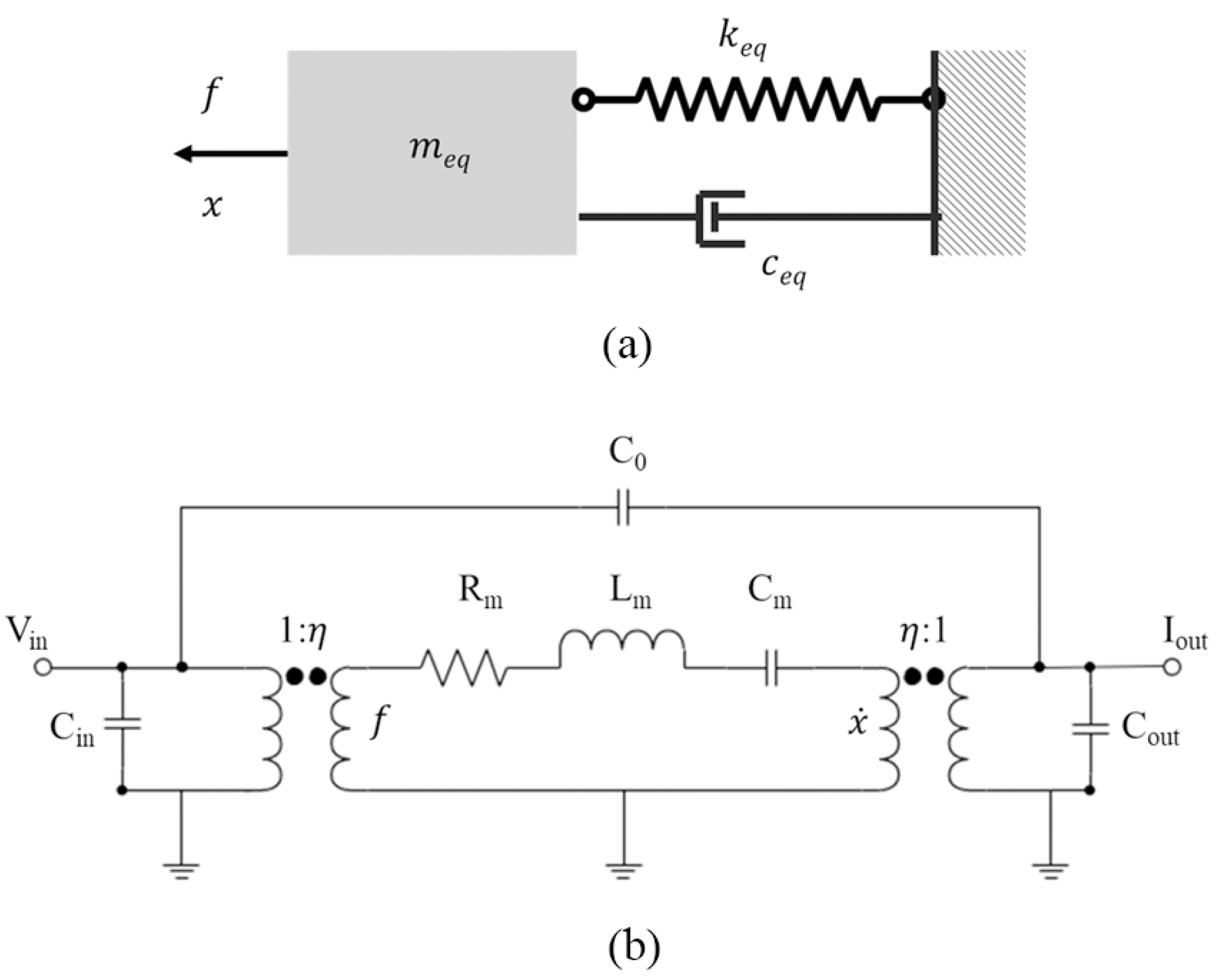
2.1. Equivalent Model
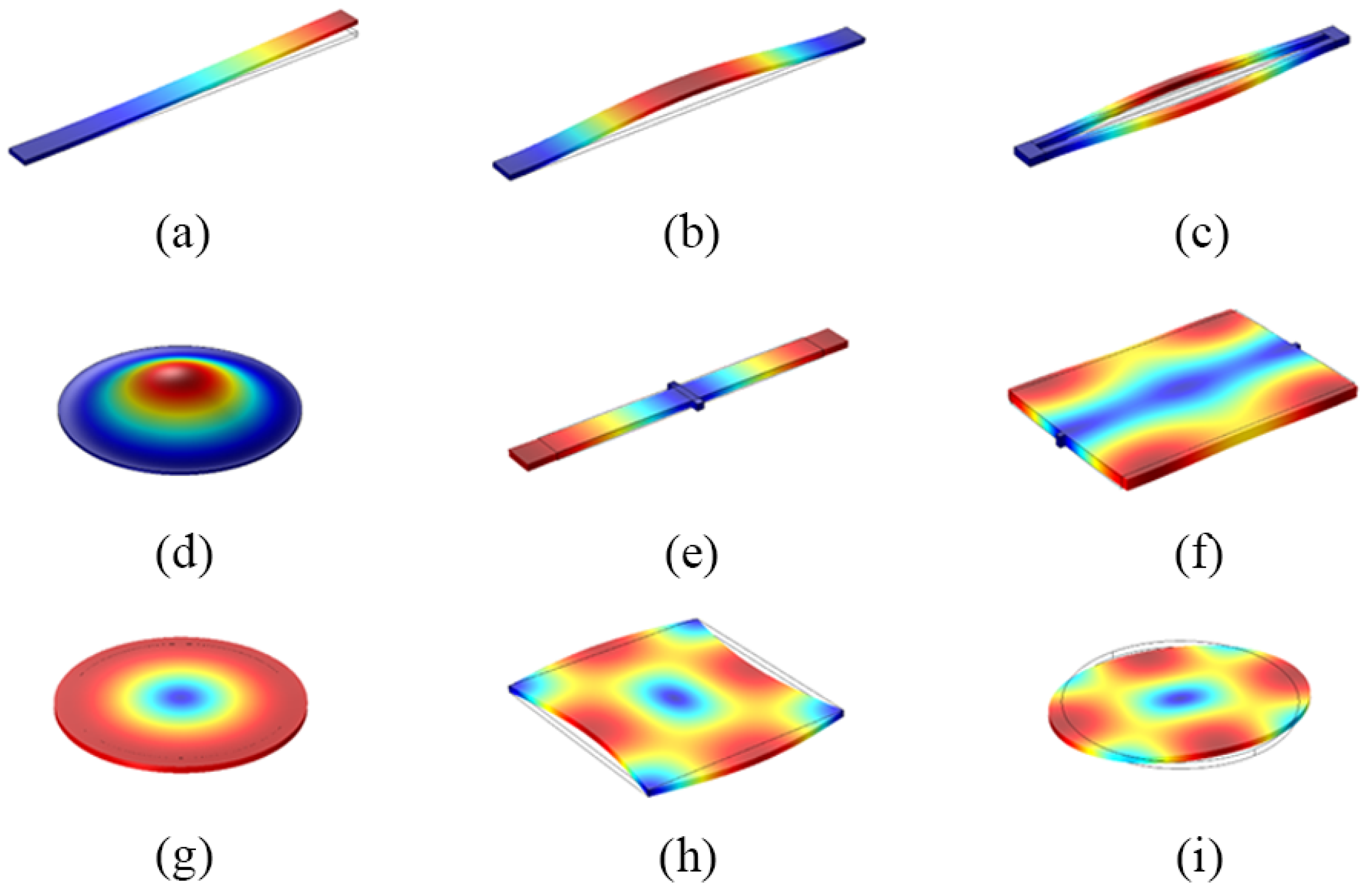
2.2. Vibration Modes
2.3. Transduction Mechanisms
3. Performance and Optimization
3.1. Quality Factor
3.1.1. Air Damping Loss
3.1.2. Anchor Loss
3.1.3. Thermoelastic Loss
3.1.4. Other Losses
3.2. Motional Resistance
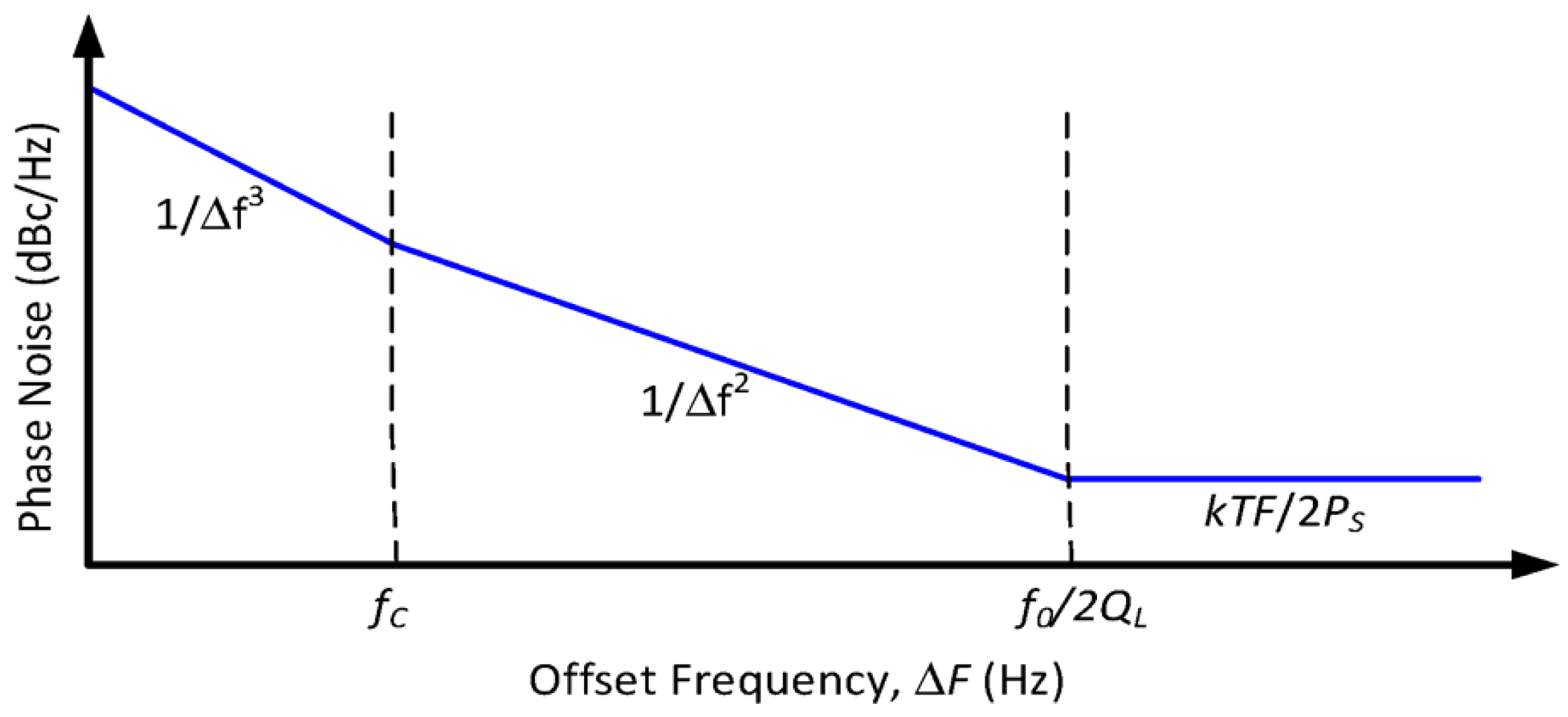
3.3. Frequency Accuracy
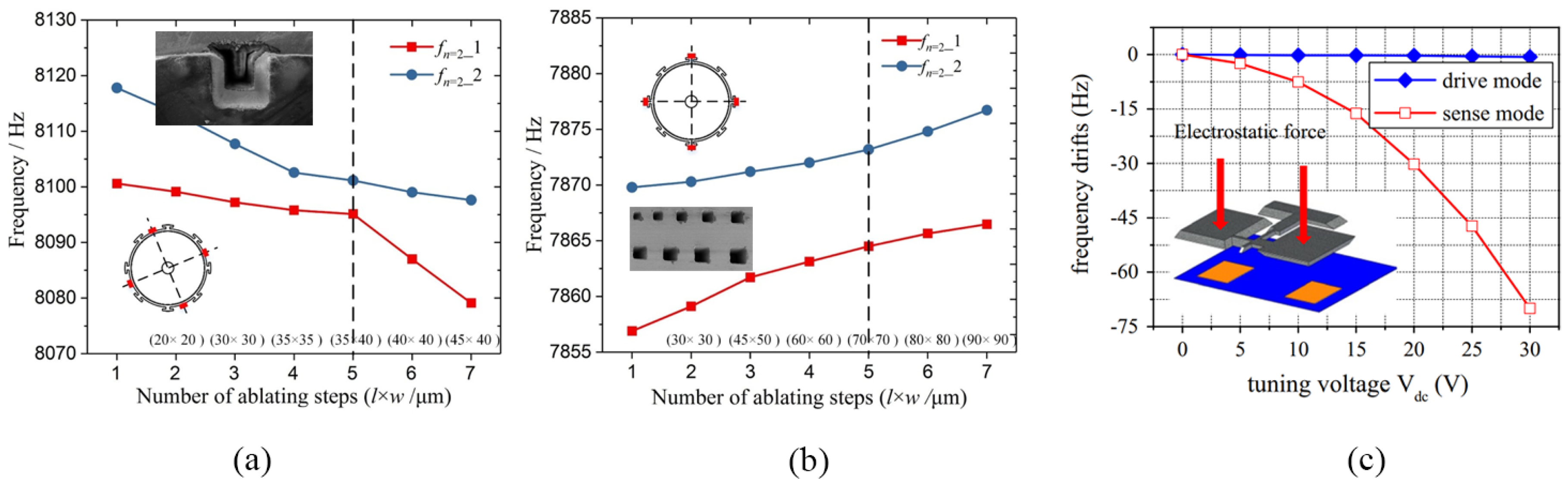
3.3.1. Mechanical Trimming
3.3.2. Electrical Tuning
3.4. Temperature Stability
3.4.1. Passive Compensation
3.4.2. Active Compensation
4. Summary and Future Perspective
Author Contributions
Funding
Data Availability Statement
Conflicts of Interest
References
- Shaeffer, D.K. MEMS Inertial Sensors: A Tutorial Overview. IEEE Commun. Mag. 2013, 51, 100–109. [Google Scholar] [CrossRef]
- Bannon, F.D.; Clark, J.R.; Nguyen, C.T.-C. High-Q HF Microelectromechanical Filters. IEEE J. Solid State Circuits 2000, 35, 512–526. [Google Scholar] [CrossRef] [Green Version]
- Nguyen, C.T.-c. MEMS Technology for Timing and Frequency Control. IEEE Trans. Ultrasonics, Ferroelectr. Freq. Control 2007, 54, 251–270. [Google Scholar] [CrossRef] [PubMed] [Green Version]
- Cong, P.; Chaimanonart, N.; Ko, W.H.; Young, D.J. A Wireless and Batteryless 10-Bit Implantable Blood Pressure Sensing Microsystem With Adaptive RF Powering for Real-Time Laboratory Mice Monitoring. IEEE J. Solid State Circ. 2009, 44, 3631–3644. [Google Scholar] [CrossRef]
- Mitcheson, P.D.; Yeatman, E.M.; Rao, G.K.; Holmes, A.S.; Green, T.C. Energy Harvesting From Human and Machine Motion for Wireless Electronic Devices. Proc. IEEE 2008, 96, 1457–1486. [Google Scholar] [CrossRef] [Green Version]
- Marek, J. MEMS for Automotive and Consumer Electronics. In Proceedings of the 2010 IEEE International Solid-State Circuits Conference-(ISSCC), San Francisco, CA, USA, 7–11 February 2010; pp. 9–17. [Google Scholar]
- Wu, G.; Xu, J.; Ng, E.J.; Chen, W. MEMS Resonators for Frequency Reference and Timing Applications. J. Microelectromech. Syst. 2020, 29, 1137–1166. [Google Scholar] [CrossRef]
- Mounier, E.; Damianos, D. Status of the MEMS Industry. Market Technol. Report Sample 2019, 1, 1–47. [Google Scholar]
- Lam, C.S. A Review of the Recent Development of MEMS and Crystal Oscillators and Their Impacts on the Frequency Control Products Industry. In Proceedings of the 2008 IEEE Ultrasonics Symposium, Beijing, China, 2 November 2008; pp. 694–704. [Google Scholar]
- Li, M.-H.; Chen, C.-Y.; Li, C.-S.; Chin, C.-H.; Li, S.-S. A Monolithic CMOS-MEMS Oscillator Based on an Ultra-Low-Power Ovenized Micromechanical Resonator. J. Microelectromech. Syst. 2015, 24, 360–372. [Google Scholar] [CrossRef]
- Sundaresan, K.; Ho, G.K.; Pourkamali, S.; Ayazi, F. Electronically Temperature Compensated Silicon Bulk Acoustic Resonator Reference Oscillators. IEEE J. Solid State Circ. 2007, 42, 1425–1434. [Google Scholar] [CrossRef]
- Zhong, J.-Y.; Zhang, Y.-Q.; Liu, Z.-J.; Yu, H.; Chen, T.-Z.; He, S.; Hu, L.; Yuan, S.; Yang, Z. Failure Case Analysis of Quartz Crystal Based on Failure Mechanism. In Proceedings of the 2017 18th International Conference on Electronic Packaging Technology (ICEPT), Harbin, China, 16–18 August 2017; pp. 1442–1445. [Google Scholar]
- Rabaey, J.M.; Ammer, J.; Karalar, T.; Li, S.; Otis, B.; Sheets, M.; Tuan, T. PicoRadios for Wireless Sensor Networks: The next Challenge in Ultra-Low Power Design. In Proceedings of the 2002 IEEE International Solid-State Circuits Conference. Digest of Technical Papers (Cat. No.02CH37315), San Francisco, CA, USA, 3–7 February 2002; Volume 1, pp. 200–201. [Google Scholar]
- Henry, R.; Kenny, D. Comparative Analysis of MEMS, Programmable, and Synthesized Frequency Control Devices versus Traditional Quartz Based Devices. In Proceedings of the 2008 IEEE International Frequency Control Symposium, New York, NY, USA, 1 May 2008; pp. 396–401. [Google Scholar]
- Yantchev, V.; Katardjiev, I. Thin Film Lamb Wave Resonators in Frequency Control and Sensing Applications: A Review. J. Micromech. Microeng. 2013, 23, 043001. [Google Scholar] [CrossRef]
- van Beek, J.T.M.; Puers, R. A Review of MEMS Oscillators for Frequency Reference and Timing Applications. J. Micromech. Microeng. 2011, 22, 013001. [Google Scholar] [CrossRef]
- Platz, D.; Schmid, U. Vibrational Modes in MEMS Resonators. J. Micromech. Microeng. 2019, 29, 123001. [Google Scholar] [CrossRef]
- Verma, G.; Mondal, K.; Gupta, A. Si-Based MEMS Resonant Sensor: A Review from Microfabrication Perspective. Microelectron. J. 2021, 118, 105210. [Google Scholar] [CrossRef]
- Ilyas, S.; Younis, M.I. Resonator-Based M/NEMS Logic Devices: Review of Recent Advances. Sens. Actuators Phys. 2020, 302, 111821. [Google Scholar] [CrossRef]
- Pillai, G.; Li, S.-S. Piezoelectric MEMS Resonators: A Review. IEEE Sens. J. 2021, 21, 12589–12605. [Google Scholar] [CrossRef]
- Tu, C.; Lee, J.E.-Y.; Zhang, X.-S. Dissipation Analysis Methods and Q-Enhancement Strategies in Piezoelectric MEMS Laterally Vibrating Resonators: A Review. Sensors 2020, 20, 4978. [Google Scholar] [CrossRef]
- Xu, J.; Tsai, J.M. A Process-Induced-Frequency-Drift Resilient 32 kHz MEMS Resonator. J. Micromechan. Microeng. 2012, 22, 105029. [Google Scholar] [CrossRef]
- Tu, C.; Lee, J.E.-Y. A Semi-Analytical Modeling Approach for Laterally-Vibrating Thin-Film Piezoelectric-on-Silicon Micromechanical Resonators. J. Micromech. Microeng. 2015, 25, 115020. [Google Scholar] [CrossRef]
- Chen, Z.; Wang, F.; Yuan, Q.; Kan, X.; Yang, J.; Zhao, J.; Yang, F. 3D-Encapsulated VHF MEMS Resonator with High Frequency Stability and Low Vibration Sensitivity. Sens. Actuators Phys. 2019, 286, 123–132. [Google Scholar] [CrossRef]
- Piazza, G.; Stephanou, P.J.; Pisano, A.P. Piezoelectric Aluminum Nitride Vibrating Contour-Mode MEMS Resonators. J. Microelectromech. Syst. 2006, 15, 1406–1418. [Google Scholar] [CrossRef] [Green Version]
- Shao, L.C.; Niu, T.; Palaniapan, M. Nonlinearities in a High-QSOI Lamé-Mode Bulk Resonator. J. Micromechan. Microeng. 2009, 19, 075002. [Google Scholar] [CrossRef]
- Chen, Z.; Wang, T.; Jia, Q.; Yang, J.; Yuan, Q.; Zhu, Y.; Yang, F. A Novel Lamé Mode RF-MEMS Resonator with High Quality Factor. Int. J. Mechan. Sci. 2021, 204, 106484. [Google Scholar] [CrossRef]
- Chen, Z.; Kan, X.; Yuan, Q.; Wang, T.; Yang, J.; Yang, F. A Switchable High-Performance RF-MEMS Resonator with Flexible Frequency Generations. Sci Rep 2020, 10, 4795. [Google Scholar] [CrossRef] [PubMed] [Green Version]
- Liu, J.; Workie, T.B.; Wu, T.; Wu, Z.; Gong, K.; Bao, J.; Hashimoto, K. Q-Factor Enhancement of Thin-Film Piezoelectric-on-Silicon MEMS Resonator by Phononic Crystal-Reflector Composite Structure. Micromachines 2020, 11, 1130. [Google Scholar] [CrossRef]
- Bao, F.-H.; Bao, J.-F.; Lee, J.E.-Y.; Bao, L.-L.; Khan, M.A.; Zhou, X.; Wu, Q.-D.; Zhang, T.; Zhang, X.-S. Quality Factor Improvement of Piezoelectric MEMS Resonator by the Conjunction of Frame Structure and Phononic Crystals. Sens. Actuators Phys. 2019, 297, 111541. [Google Scholar] [CrossRef]
- Deshpande, P.P.; Pande, R.S.; Patrikar, R.M. Fabrication and Characterization of Zinc Oxide Piezoelectric MEMS Resonator. Microsyst. Technol. 2020, 26, 415–423. [Google Scholar] [CrossRef]
- Will-Cole, A.R.; Hassanien, A.E.; Calisgan, S.D.; Jeong, M.-G.; Liang, X.; Kang, S.; Rajaram, V.; Martos-Repath, I.; Chen, H.; Risso, A.; et al. Tutorial: Piezoelectric and Magnetoelectric N/MEMS—Materials, Devices, and Applications. J. Appl. Phys. 2022, 131, 241101. [Google Scholar] [CrossRef]
- Ben-Shimon, Y.; Ya’akobovitz, A. Magnetic Excitation and Dissipation of Multilayer Two-Dimensional Resonators. Appl. Phys. Lett. 2021, 118, 063103. [Google Scholar] [CrossRef]
- Wei, L.; You, Z.; Kuai, X.; Zhang, M.; Yang, F.; Wang, X. MEMS Thermal-Piezoresistive Resonators, Thermal-Piezoresistive Oscillators, and Sensors. Microsyst. Technol. 2022, 29, 1–17. [Google Scholar] [CrossRef]
- Zope, A.A.; Chang, J.-H.; Liu, T.-Y.; Li, S.-S. A CMOS-MEMS Thermal-Piezoresistive Oscillator for Mass Sensing Applications. IEEE Trans. Electron. Dev. 2020, 67, 1183–1191. [Google Scholar] [CrossRef]
- Setiono, A.; Xu, J.; Fahrbach, M.; Bertke, M.; Nyang’au, W.O.; Wasisto, H.S.; Peiner, E. Real-Time Frequency Tracking of an Electro-Thermal Piezoresistive Cantilever Resonator with ZnO Nanorods for Chemical Sensing. Chemosensors 2019, 7, 2. [Google Scholar] [CrossRef]
- Dennis, J.; Ahmed, A.; Khir, M.M.; Rabih, A. Modelling and Simulation of the Effect of Air Damping on the Frequency and Quality Factor of a CMOS-MEMS Resonator. Appl. Math. Infor. Sci. 2015, 9, 729–737. [Google Scholar]
- Jaber, N.; Ilyas, S.; Shekhah, O.; Eddaoudi, M.; Younis, M.I. Multimode MEMS Resonator for Simultaneous Sensing of Vapor Concentration and Temperature. IEEE Sens. J. 2018, 18, 10145–10153. [Google Scholar] [CrossRef]
- Li, S.-S.; Lin, Y.-W.; Xie, Y.; Ren, Z.; Nguyen, C.T.-C. Micromechanical “Hollow-Disk” Ring Resonators. In Proceedings of the 17th IEEE International Conference on Micro Electro Mechanical Systems. Maastricht MEMS 2004 Technical Digest, New York, NY, USA, 25–29 January 2004; pp. 821–824. [Google Scholar]
- Pandey, M.; Reichenbach, R.B.; Zehnder, A.T.; Lal, A.; Craighead, H.G. Reducing Anchor Loss in MEMS Resonators Using Mesa Isolation. J. Microelectromech. Syst. 2009, 18, 836–844. [Google Scholar] [CrossRef]
- Zhang, Y.; Bao, J.-F.; Zhou, X.; Wu, Z.-H.; Bao, F.-H.; Zhang, X.-S. A 10 MHz Thin-Film Piezoelectric-on-Silicon MEMS Resonator with T-Shaped Tethers for Q Enhancement. Jpn. J. Appl. Phys. 2019, 59, 014002. [Google Scholar] [CrossRef]
- Li, J.; Chen, Z.; Liu, W.; Yang, J.; Zhu, Y.; Yang, F. A Novel Piezoelectric RF-MEMS Resonator with Enhanced Quality Factor. J. Micromech. Microeng. 2022, 32, 035002. [Google Scholar] [CrossRef]
- Awad, M.; Bao, F.; Bao, J.; Zhang, X. Cross-Shaped PnC for Anchor Loss Reduction of Thin-Film ALN-on-Silicon High Frequency MEMS Resonator. In Proceedings of the 2018 IEEE MTT-S International Wireless Symposium (IWS), New York, NY, USA, 6–10 May 2018; pp. 1–3. [Google Scholar]
- Siddiqi, M.W.U.; Lee, J.E.-Y. AlN-on-Si MEMS Resonator Bounded by Wide Acoustic Bandgap Two-Dimensional Phononic Crystal Anchors. In Proceedings of the 2018 IEEE Micro Electro Mechanical Systems (MEMS), Belfast, UK, 21–25 January 2018; pp. 727–730. [Google Scholar]
- Workie, T.B.; Wu, T.; Bao, J.-F.; Hashimoto, K. Design for High-Quality Factor of Piezoelectric-on-Silicon MEMS Resonators Using Resonant Plate Shape and Phononic Crystals. Jpn. J. Appl. Phys. 2021, 60, SDDA03. [Google Scholar] [CrossRef]
- Ha, T.D. Boosted Anchor Quality Factor of a Thin-Film Aluminum Nitride-on-Silicon Length Extensional Mode MEMS Resonator Using Phononic Crystal Strip. Appl. Phys. A 2021, 127, 738. [Google Scholar] [CrossRef]
- Bao, F.-H.; Awad, M.; Li, X.-Y.; Wu, Z.-H.; Bao, J.-F.; Zhang, X.-S.; Bao, L.-L. Suspended Frame Structure with Phononic Crystals for Anchor Loss Reduction of MEMS Resonator. In Proceedings of the 2018 IEEE International Frequency Control Symposium (IFCS), Olympic Valley, CA, USA, 21–24 May 2018; pp. 1–4. [Google Scholar]
- Wu, X.; Bao, F.; Zhou, X.; Wu, Q.; Liu, J.; Bao, J. Spider Web-Shaped Phononic Crystals for Quality Factor Improvement of Piezoelectric-on-Silicon MEMS Resonators. In Proceedings of the 2019 IEEE International Ultrasonics Symposium (IUS), Glasgow, UK, 6–9 October 2019; pp. 1724–1726. [Google Scholar]
- Khan, M.A.; Bao, J.; Farooq, M.U. Framing Holes Phononic Crystal Structure for Q-Factor Enhancement of Thin-Film-Piezoelectric-on-Silicon MEMS Resonator. J. Optoelectron. Adv. Mater. 2021, 23, 472–476. [Google Scholar]
- Asadi, S.; Sheikholeslami, T.F. Effects of Slots on Thermoelastic Quality Factor of a Vertical Beam MEMS Resonator. Microsyst. Technol. 2016, 22, 2723–2730. [Google Scholar] [CrossRef]
- Zega, V.; Frangi, A.; Guercilena, A.; Gattere, G. Analysis of Frequency Stability and Thermoelastic Effects for Slotted Tuning Fork MEMS Resonators. Sensors 2018, 18, 2157. [Google Scholar] [CrossRef] [PubMed] [Green Version]
- Qiu, H.; Ababneh, A.; Feili, D.; Wu, X.; Seidel, H. Analysis of Intrinsic Damping in Vibrating Piezoelectric Microcantilevers. Microsyst. Technol. 2016, 22, 2017–2025. [Google Scholar] [CrossRef]
- Zuo, W.; Li, P.; Du, J.; Tse, Z.T.H. Thermoelastic Damping in Anisotropic Piezoelectric Microbeam Resonators. Int. J. Heat Mass Transf. 2022, 199, 123493. [Google Scholar] [CrossRef]
- Zener, C. Internal Friction in Solids. I. Theory of Internal Friction in Reeds. Phys. Rev. 1937, 52, 230–235. [Google Scholar] [CrossRef]
- Duwel, A.; Candler, R.N.; Kenny, T.W.; Varghese, M. Engineering MEMS Resonators With Low Thermoelastic Damping. J. Microelectromech. Syst. 2006, 15, 1437–1445. [Google Scholar] [CrossRef]
- Chandorkar, S.A.; Candler, R.N.; Duwel, A.; Melamud, R.; Agarwal, M.; Goodson, K.E.; Kenny, T.W. Multimode Thermoelastic Dissipation. J. Appl. Phys. 2009, 105, 043505. [Google Scholar] [CrossRef] [Green Version]
- Duwel, A.; Gorman, J.; Weinstein, M.; Borenstein, J.; Ward, P. Experimental Study of Thermoelastic Damping in MEMS Gyros. Sens. Actuators Phys. 2003, 103, 70–75. [Google Scholar] [CrossRef] [Green Version]
- Candler, R.N.; Hopcroft, M.; Low, C.W.; Chandorkar, S.; Kim, B.; Varghese, M.; Duwel, A.; Kenny, T.W. Impact of Slot Location on Thermoelastic Dissipation in Micromechanical Resonators. In Proceedings of the 13th International Conference on Solid-State Sensors, Actuators and Microsystems, 2005. Digest of Technical Papers. TRANSDUCERS ’05, New York, NY, USA, 5–9 June 2005; Volume 1, pp. 597–600. [Google Scholar]
- Segovia-Fernandez, J. Damping in Aluminum Nitride Contour Mode MEMS Resonators. In Proceedings of the 2017 IEEE 60th International Midwest Symposium on Circuits and Systems (MWSCAS), Boston, MA, USA, 6–9 August 2017; pp. 49–52. [Google Scholar]
- Yang, L.; Li, P.; Fang, Y.; Ge, X. Thermoelastic Damping in Partially Covered Bilayer Microbeam Resonators with Two-Dimensional Heat Conduction. J. Sound Vibr. 2021, 494, 115863. [Google Scholar] [CrossRef]
- Dohn, S.; Sandberg, R.; Svendsen, W.; Boisen, A. Enhanced Functionality of Cantilever Based Mass Sensors Using Higher Modes and Functionalized Particles. In Proceedings of the 13th International Conference on Solid-State Sensors, Actuators and Microsystems, 2005. Digest of Technical Papers. TRANSDUCERS ’05, Seoul, Republic of Korea, 1 June 2005; Volume 1, pp. 636–639. [Google Scholar]
- Jen, H.-T.; Pillai, G.; Liu, S.-I.; Li, S.-S. High-Q Support Transducer MEMS Resonators Enabled Low-Phase-Noise Oscillators. IEEE Trans. Ultrason. Ferroelectr. Freq. Control 2021, 68, 1387–1398. [Google Scholar] [CrossRef]
- Sang, L.; Liao, M.; Yang, X.; Sun, H.; Zhang, J.; Sumiya, M.; Shen, B. Strain-Enhanced High Q-Factor GaN Micro-Electromechanical Resonator. Sci. Technol. Adv. Mater. 2020, 21, 515–523. [Google Scholar] [CrossRef]
- Bao, F.-H.; Wu, Q.-D.; Zhou, X.; Wu, T.; Li, X.-Y.; Bao, J.-F. High-Q Multi-Frequency Ring-Shaped Piezoelectric MEMS Resonators. Microelectron. J. 2020, 98, 104733. [Google Scholar] [CrossRef]
- Ibach, H. The Role of Surface Stress in Reconstruction, Epitaxial Growth and Stabilization of Mesoscopic Structures. Surface Science Reports 1997, 29, 195–263. [Google Scholar] [CrossRef]
- Sobreviela, G.; Uranga, A.; Barniol, N. Tunable Transimpedance Sustaining-Amplifier for High Impedance CMOS-MEMS Resonators. In Proceedings of the 2014 10th Conference on Ph.D. Research in Microelectronics and Electronics (PRIME), Grenoble, France, 1 June 2014; pp. 1–4. [Google Scholar]
- DeVoe, D.L. Piezoelectric Thin Film Micromechanical Beam Resonators. Sens. Actuators Phys. 2001, 88, 263–272. [Google Scholar] [CrossRef]
- Lee, S.; Nguyen, C.T.-C. Mechanically-Coupled Micromechanical Resonator Arrays for Improved Phase Noise. In Proceedings of the Proceedings of the 2004 IEEE International Frequency Control Symposium and Exposition, Montréal, QC, Canada, 23–27 August 2004; pp. 144–150. [Google Scholar]
- Belsito, L.; Bosi, M.; Mancarella, F.; Ferri, M.; Roncaglia, A. Nanostrain Resolution Strain Sensing by Monocrystalline 3C-SiC on SOI Electrostatic MEMS Resonators. J. Microelectromech. Syst. 2020, 29, 117–128. [Google Scholar] [CrossRef]
- Ayazi, F.; Najafi, K. High Aspect-Ratio Combined Poly and Single-Crystal Silicon (HARPSS) MEMS Technology. J. Microelectromech. Syst. 2000, 9, 288–294. [Google Scholar] [CrossRef]
- Pourkamali, S.; Ayazi, F. SOI-Based HF and VHF Single-Crystal Silicon Resonators with SUB-100 Nanometer Vertical Capacitive Gaps. In Proceedings of the TRANSDUCERS ’03. 12th International Conference on Solid-State Sensors, Actuators and Microsystems. Digest of Technical Papers (Cat. No.03TH8664), Boston, MA, USA, 8–12 June 2003; Volume 1, pp. 837–840. [Google Scholar]
- Demirci, M.U.; Nguyen, C.T.-C. Mechanically Corner-Coupled Square Microresonator Array for Reduced Series Motional Resistance. J. Microelectromech. Syst. 2006, 15, 1419–1436. [Google Scholar] [CrossRef] [Green Version]
- Erbes, A.; Thiruvenkatanathan, P.; Woodhouse, J.; Seshia, A.A. Numerical Study of the Impact of Vibration Localization on the Motional Resistance of Weakly Coupled MEMS Resonators. J. Microelectromech. Syst. 2015, 24, 997–1005. [Google Scholar] [CrossRef]
- Weinstein, D.; Bhave, S.A.; Tada, M.; Mitarai, S.; Morita, S.; Ikeda, K. Mechanical Coupling of 2D Resonator Arrays for MEMS Filter Applications. In Proceedings of the 2007 IEEE International Frequency Control Symposium Joint with the 21st European Frequency and Time Forum, Paris, France, 1 May 2007; pp. 1362–1365. [Google Scholar]
- Bharadwaj Chivukula, V.; Rhoads, J.F. Microelectromechanical Bandpass Filters Based on Cyclic Coupling Architectures. J. Sound Vibr. 2010, 329, 4313–4332. [Google Scholar] [CrossRef]
- Jiang, J.W.; Bao, J.F.; Du, Y.J.; Deng, C. A Novel Movable Electrode for Realizing Deep Sub-Micrometer Gap in SOI-Based MEMS Square Resonator. Microsyst. Technol. 2013, 19, 763–772. [Google Scholar] [CrossRef]
- Hajjam, A.; Pourkamali, S. Self-Contained Frequency Trimming of Micromachined Silicon Resonators via Localized Thermal Oxidation. J. Microelectromech. Syst. 2013, 22, 1066–1072. [Google Scholar] [CrossRef]
- Samarao, A.K.; Ayazi, F. Postfabrication Electrical Trimming of Silicon Micromechanical Resonators via Joule Heating. J. Microelectromech. Syst. 2011, 20, 1081–1088. [Google Scholar] [CrossRef]
- You, W.; Yang, H.; Pei, B.; Sun, K.; Li, X. Frequency Trimming of Silicon Resonators after Package with Integrated Micro-Evaporators. In Proceedings of the 2017 IEEE 30th International Conference on Micro Electro Mechanical Systems (MEMS), New York, NY, USA, 1 January 2017; pp. 917–919. [Google Scholar]
- Hsu, W.-T.; Brown, A.R. Frequency Trimming for MEMS Resonator Oscillators. In Proceedings of the 2007 IEEE International Frequency Control Symposium Joint with the 21st European Frequency and Time Forum, Paris, France, 29 May 2007; pp. 1088–1091. [Google Scholar]
- Lu, K.; Xi, X.; Li, W.; Shi, Y.; Hou, Z.; Zhuo, M.; Wu, X.; Wu, Y.; Xiao, D. Research on Precise Mechanical Trimming of a Micro Shell Resonator with T-Shape Masses Using Femtosecond Laser Ablation. Sens. Actuators Phys. 2019, 290, 228–238. [Google Scholar] [CrossRef]
- Li, W.; Xiao, D.; Wu, X.; Su, J.; Chen, Z.; Hou, Z.; Wang, X. Enhanced Temperature Stability of Sensitivity for MEMS Gyroscope Based on Frequency Mismatch Control. Microsystem. Technol. 2017, 23, 3311–3317. [Google Scholar] [CrossRef]
- Pei, B.; Zhong, P.; Sun, K.; Yang, H.; Li, X. Micro-Oven-Controlled MEMS Oscillator with Electrostatic Tuning for Frequency Trimming. In Proceedings of the 2018 IEEE Micro Electro Mechanical Systems (MEMS), New York, NY, USA, 20 January 2018; pp. 731–734. [Google Scholar]
- Serrano, D.E.; Tabrizian, R.; Ayazi, F. Tunable Piezoelectric MEMS Resonators for Real-Time Clock. In Proceedings of the 2011 Joint Conference of the IEEE International Frequency Control and the European Frequency and Time Forum (FCS) Proceedings, Paris, France, 18 May 2011; pp. 1–4. [Google Scholar]
- Ghasemi, S.; Afrang, S.; Rezazadeh, G.; Darbasi, S.; Sotoudeh, B. On the Mechanical Behavior of a Wide Tunable Capacitive MEMS Resonator for Low Frequency Energy Harvesting Applications. Microsyst. Technol. 2020, 26, 2389–2398. [Google Scholar] [CrossRef]
- Lin, Y.; Li, W.-C.; Kim, B.; Lin, Y.-W.; Ren, Z.; Nguyen, C.T.-C. Enhancement of Micromechanical Resonator Manufacturing Precision via Mechanically-Coupled Arraying. In Proceedings of the 2009 IEEE International Frequency Control Symposium Joint with the 22nd European Frequency and Time Forum, Paris, France, 20–24 April 2009; pp. 58–63. [Google Scholar]
- Jiang, B.; Huang, S.; Zhang, J.; Su, Y. Analysis of Frequency Drift of Silicon MEMS Resonator with Temperature. Micromachines 2021, 12, 26. [Google Scholar] [CrossRef] [PubMed]
- Shahmohammadi, M.; Harrington, B.P.; Abdolvand, R. Turnover Temperature Point in Extensional-Mode Highly Doped Silicon Microresonators. IEEE Trans. Electron. Dev. 2013, 60, 1213–1220. [Google Scholar] [CrossRef]
- Melamud, R.; Chandorkar, S.A.; Kim, B.; Lee, H.K.; Salvia, J.C.; Bahl, G.; Hopcroft, M.A.; Kenny, T.W. Temperature-Insensitive Composite Micromechanical Resonators. J. Microelectromech. Syst. 2009, 18, 1409–1419. [Google Scholar] [CrossRef]
- Jaakkola, A.; Pekko, P.; Dekker, J.; Prunnila, M.; Pensala, T. Second Order Temperature Compensated Piezoelectrically Driven 23 MHz Heavily Doped Silicon Resonators with ±10 ppm Temperature Stability. In Proceedings of the 2015 Joint Conference of the IEEE International Frequency Control Symposium & the European Frequency and Time Forum, Paris, France, 12–16 April 2015; pp. 420–422. [Google Scholar]
- Kim, B.; Melamud, R.; Hopcroft, M.A.; Chandorkar, S.A.; Bahl, G.; Messana, M.; Candler, R.N.; Yama, G.; Kenny, T. Si-SiO2 Composite MEMS Resonators in CMOS Compatible Wafer-Scale Thin-Film Encapsulation. In Proceedings of the 2007 IEEE International Frequency Control Symposium Joint with the 21st European Frequency and Time Forum, Paris, France, 29 May–1 June 2007; pp. 1214–1219. [Google Scholar]
- Melamud, R.; Kim, B.; Hopcroft, M.A.; Chandorkar, S.; Agarwal, M.; Jha, C.M.; Kenny, T.W. Composite Flexural-Mode Resonator with Controllable Turnover Temperature. In Proceedings of the 2007 IEEE 20th International Conference on Micro Electro Mechanical Systems (MEMS), Hyogo, Japan, 14 January 2007; pp. 199–202. [Google Scholar]
- Wu, Z.; Rais-Zadeh, M. A Temperature-Stable Piezoelectric MEMS Oscillator Using a CMOS PLL Circuit for Temperature Sensing and Oven Control. J. Microelectromech. Syst. 2015, 24, 1747–1758. [Google Scholar] [CrossRef]
- Lin, C.-M.; Yen, T.-T.; Lai, Y.-J.; Felmetsger, V.V.; Hopcroft, M.A.; Kuypers, J.H.; Pisano, A.P. Experimental Study of Temperature-Compensated Aluminum Nitride Lamb Wave Resonators. In Proceedings of the 2009 IEEE International Frequency Control Symposium Joint with the 22nd European Frequency and Time Forum, Paris, France, 15–18 April 2009; pp. 5–9. [Google Scholar]
- Schwartz, S.A.; Brand, O.; Beardslee, L.A. Temperature Compensation of Thermally Actuated, In-Plane Resonant Gas Sensor Using Embedded Oxide-Filled Trenches. J. Microelectromech. Syst. 2020, 29, 936–941. [Google Scholar] [CrossRef]
- Samarao, A.K.; Ayazi, F. Temperature Compensation of Silicon Micromechanical Resonators via Degenerate Doping. In Proceedings of the 2009 IEEE International Electron Devices Meeting (IEDM), Baltimore, MD, USA, 7–9 December 2009; pp. 1–4. [Google Scholar]
- Samarao, A.K.; Ayazi, F. Temperature Compensation of Silicon Resonators via Degenerate Doping. IEEE Trans. Electron. Dev. 2012, 59, 87–93. [Google Scholar] [CrossRef]
- Hajjam, A.; Logan, A.; Pourkamali, S. Doping-Induced Temperature Compensation of Thermally Actuated High-Frequency Silicon Micromechanical Resonators. J. Microelectromech. Syst. 2012, 21, 681–687. [Google Scholar] [CrossRef]
- Ng, E.J.; Hong, V.A.; Yang, Y.; Ahn, C.H.; Everhart, C.L.M.; Kenny, T.W. Temperature Dependence of the Elastic Constants of Doped Silicon. J. Microelectromech. Syst. 2015, 24, 730–741. [Google Scholar] [CrossRef]
- Bourgeois, C.; Steinsland, E.; Blanc, N.; de Rooij, N.F. Design of Resonators for the Determination of the Temperature Coefficients of Elastic Constants of Monocrystalline Silicon. In Proceedings of the Proceedings of International Frequency Control Symposium, New York, NY, USA, 7–17 May 1997; pp. 791–799. [Google Scholar]
- Han, J.; Xiao, Y.; Chen, W.; Jia, W.; Zhu, K.; Wu, G. Temperature Compensated Bulk-Mode Capacitive MEMS Resonators With ±16 ppm Temperature Stability Over Industrial Temperature Ranges. J. Microelectromech. Syst. 2022, 31, 723–725. [Google Scholar] [CrossRef]
- Ahmed, H.; Rajai, P.; Ahamed, M.J. Temperature Frequency Stability Study of Extensional Mode N-Doped Silicon MEMS Resonator. AIP Adv. 2022, 12, 015319. [Google Scholar] [CrossRef]
- Samarao, A.K.; Casinovi, G.; Ayazi, F. Passive TCF Compensation in High Q Silicon Micromechanical Resonators. In Proceedings of the 2010 IEEE 23rd International Conference on Micro Electro Mechanical Systems (MEMS), London, UK, 24–28 January 2010; pp. 116–119. [Google Scholar]
- Zega, V.; Opreni, A.; Mussi, G.; Kwon, H.-K.; Vukasin, G.; Gattere, G.; Langfelder, G.; Frangi, A.; Kenny, T.W. Thermal Stability of DETF MEMS Resonators: Numerical Modelling and Experimental Validation. In Proceedings of the 2020 IEEE 33rd International Conference on Micro Electro Mechanical Systems (MEMS), Vancouver, BC, Canada, 18–22 January 2020; pp. 1207–1210. [Google Scholar]
- Jaakkola, A.; Prunnila, M.; Pensala, T. Temperature Compensated Resonance Modes of Degenerately N-Doped Silicon MEMS Resonators. In Proceedings of the 2012 IEEE International Frequency Control Symposium Proceedings, Baltimore, MD, USA, 21–24 May 2012; pp. 1–5. [Google Scholar]
- Jaakkola, A.; Prunnila, M.; Pensala, T.; Dekker, J.; Pekko, P. Design Rules for Temperature Compensated Degenerately N-Type-Doped Silicon MEMS Resonators. J. Microelectromech. Syst. 2015, 24, 1832–1839. [Google Scholar] [CrossRef]
- Jaakkola, A.; Prunnila, M.; Pensala, T.; Dekker, J.; Pekko, P. Determination of Doping and Temperature-Dependent Elastic Constants of Degenerately Doped Silicon from MEMS Resonators. IEEE Trans. Ultrason. Ferroelectr. Frequency Contr. 2014, 61, 3007. [Google Scholar] [CrossRef] [Green Version]
- Jaakkola, A.; Prunnila, M.; Pensala, T.; Dekker, J.; Pekko, P. Experimental Determination of the Temperature Dependency of the Elastic Constants of Degenerately Doped Silicon. In Proceedings of the 2013 Joint European Frequency and Time Forum & International Frequency Control Symposium (EFTF/IFC), Prague, Czech Republic, 21–24 July 2013; pp. 421–424. [Google Scholar]
- Ng, E.J.; Ahn, C.H.; Yang, Y.; Hong, V.A.; Chiang, C.-F.; Ahadi, E.; Ward, M.W.; Kenny, T.W. Localized, Degenerately Doped Epitaxial Silicon for Temperature Compensation of Resonant MEMS Systems. In Proceedings of the 2013 Transducers & Eurosensors XXVII: The 17th International Conference on Solid-State Sensors, Actuators and Microsystems (TRANSDUCERS & EUROSENSORS XXVII), Barcelona, Spain, 16–19 June 2013; pp. 2419–2422. [Google Scholar]
- Holloway, H.; McCarthy, S.L. Determination of the Lattice Contraction of Boron-Doped Silicon. J. Appl. Phys. 1993, 73. [Google Scholar] [CrossRef]
- Ghosh, S.; Sharma, J.; Ng, E.J.; Goh, D.J.; Merugu, S.; Koh, Y.; Lal, A. Reduced TCF, High Frequency, Piezoelectric Contour-Mode Resonators with Silicon-on-Nothing. In Proceedings of the 2021 IEEE International Ultrasonics Symposium (IUS), Online, 11–16 September 2021; pp. 1–4. [Google Scholar]
- Chen, W.; Jia, W.; Xiao, Y.; Feng, Z.; Wu, G. A Temperature-Stable and Low Impedance Piezoelectric MEMS Resonator for Drop-in Replacement of Quartz Crystals. IEEE Electron. Dev. Lett. 2021, 42, 1382–1385. [Google Scholar] [CrossRef]
- Ho, G.K.K.; Sundaresan, K.; Pourkamali, S.; Ayazi, F. Temperature Compensated IBAR Reference Oscillators. In Proceedings of the 19th IEEE International Conference on Micro Electro Mechanical Systems, Istanbul, Turkey, 22–26 January 2006; pp. 910–913. [Google Scholar]
- Ho, G.K.; Sundaresan, K.; Pourkamali, S.; Ayazi, F. Low-Motional-Impedance Highly-Tunable I2 Resonators for Temperature-Compensated Reference Oscillators. In Proceedings of the 18th IEEE International Conference on Micro Electro Mechanical Systems, Estoril, Portugal, 18–22 January 2015. [Google Scholar]
- Sundaresan, K.; Ho, G.K.; Pourkamali, S.; Ayazi, F. A Two-Chip, 4-MHz, Microelectromechanical Reference Oscillator. In Proceedings of the 2005 IEEE International Symposium on Circuits and Systems, New York, NY, USA, 23–26 May 2005; Volume 6, pp. 5461–5464. [Google Scholar]
- Serrano, D.E.; Tabrizian, R.; Ayazi, F. Electrostatically tunable piezoelectric-on-silicon micromechanical resonator for real-time clock. IEEE Trans. Ultrason. Ferroelectr. Freq. Control 2012, 59, 358–365. [Google Scholar] [CrossRef]
- Lee, H.K.; Melamud, R.; Kim, B.; Hopcroft, M.A.; Salvia, J.C.; Kenny, T.W. Electrostatic Tuning to Achieve Higher Stability Microelectromechanical Composite Resonators. J. Microelectromech. Syst. 2011, 20, 1355–1365. [Google Scholar] [CrossRef]
- Liu, J.-R.; Li, W.-C. A Temperature-Insensitive CMOS-MEMS Resonator Utilizing Electrical Stiffness Compensation. In Proceedings of the 2019 IEEE 32nd International Conference on Micro Electro Mechanical Systems (MEMS), Beijing, China, 25 January 2019; pp. 161–164. [Google Scholar]
- Lutz, M.; Partridge, A.; Gupta, P.; Buchan, N.; Klaassen, E.; McDonald, J.; Petersen, K. MEMS Oscillators for High Volume Commercial Applications. In Proceedings of the TRANSDUCERS 2007-2007 International Solid-State Sensors, Actuators and Microsystems Conference, Lyon, France, 10–14 June 2007; pp. 49–52. [Google Scholar]
- Perrott, M.H.; Salvia, J.C.; Lee, F.S.; Partridge, A.; Mukherjee, S.; Arft, C.; Kim, J.; Arumugam, N.; Gupta, P.; Tabatabaei, S.; et al. A Temperature-to-Digital Converter for a MEMS-Based Programmable Oscillator with <±0.5- ppm Frequency Stability and < 1-Ps Integrated Jitter. IEEE J. Solid State Circ. 2013, 48. [Google Scholar] [CrossRef]
- Roshan, M.H.; Zaliasl, S.; Joo, K.; Souri, K.; Palwai, R.; Chen, L.; Singh, A.; Pamarti, S.; Miller, N.J.; Doll, J.C.; et al. A MEMS-Assisted Temperature Sensor With 20-ΜK Resolution, Conversion Rate of 200 S/s, and FOM of 0.04 PJK2. IEEE J. Solid State Circ. 2017, 52. [Google Scholar] [CrossRef]
- Wu, G.; Xu, J.; Zhang, X.; Wang, N.; Yan, D.; Lim, J.L.K.; Zhu, Y.; Li, W.; Gu, Y. Wafer-Level Vacuum-Packaged High-Performance AlN-on-SOI Piezoelectric Resonator for Sub-100- MHz Oscillator Applications. IEEE Trans. Ind. Electron. 2018, 65, 3576–3584. [Google Scholar] [CrossRef]
- Mussi, G.; Frigerio, P.; Gattere, G.; Langfelder, G. A MEMS Real-Time Clock With Single-Temperature Calibration and Deterministic Jitter Cancellation. IEEE Trans. Ultrason. Ferroelectr. Frequency Contr. 2021, 68, 880–889. [Google Scholar] [CrossRef]
- Salvia, J.C.; Melamud, R.; Chandorkar, S.A.; Lord, S.F.; Kenny, T.W. Real-Time Temperature Compensation of MEMS Oscillators Using an Integrated Micro-Oven and a Phase-Locked Loop. J. Microelectromech. Syst. 2010, 19, 192–201. [Google Scholar] [CrossRef]
- Tazzoli, A.; Kuo, N.-K.; Rinaldi, M.; Pak, H.; Fry, D.; Bail, D.; Stevens, D.; Piazza, G. A 586 MHz Microcontroller Compensated MEMS Oscillator Based on Ovenized Aluminum Nitride Contour-Mode Resonators. In Proceedings of the 2012 IEEE International Ultrasonics Symposium, Berlin, Germany, 7–10 October 2012; pp. 1055–1058. [Google Scholar]
- Jha, C.M.; Hopcroft, M.A.; Chandorkar, S.A.; Salvia, J.C.; Agarwal, M.; Candler, R.N.; Melamud, R.; Kim, B.; Kenny, T.W. Thermal Isolation of Encapsulated MEMS Resonators. J. Microelectromech. Syst. 2008, 17, 175–184. [Google Scholar] [CrossRef] [Green Version]
- Liu, C.S.; Tabrizian, R.; Ayazi, F. A ±0.3 ppm Oven-Controlled MEMS Oscillator Using Structural Resistance-Based Temperature Sensing. IEEE Trans. Ultrason. Ferroelectr. Frequency Contr. 2018, 65. [Google Scholar] [CrossRef]
- You, W.; Pei, B.; Sun, K.; Zhang, L.; Yang, H.; Li, X. Oven Controlled N++ [1 0 0] Length-Extensional Mode Silicon Resonator with Frequency Stability of 1 ppm over Industrial Temperature Range. J. Micromech. Microeng. 2017, 27, 095002. [Google Scholar] [CrossRef]
- Comenencia Ortiz, L.; Kwon, H.-K.; Rodriguez, J.; Chen, Y.; Vukasin, G.D.; Heinz, D.B.; Shin, D.D.; Kenny, T.W. Low-Power Dual Mode MEMS Resonators With PPB Stability Over Temperature. J. Microelectromech. Syst. 2020, 29, 190–201. [Google Scholar] [CrossRef]
- Jia, W.; Chen, W.; Xiao, Y.; Wu, Z.; Wu, G. A Micro-Oven-Controlled Dual-Mode Piezoelectric MEMS Resonator with ±400 PPB Stability over −40 to 80 °C Temperature Range. IEEE Trans. Electron. Dev. 2022, 69. [Google Scholar] [CrossRef]
- Chen, Y.; Ng, E.J.; Shin, D.D.; Ahn, C.H.; Yang, Y.; Flader, I.B.; Hong, V.A.; Kenny, T.W. Ovenized Dual-Mode Clock (ODMC) Based on Highly Doped Single Crystal Silicon Resonators. In Proceedings of the 2016 IEEE 29th International Conference on Micro Electro Mechanical Systems (MEMS), Shanghai, China, 24–28 October 2016; pp. 91–94. [Google Scholar]
- Kwon, H.-K.; Ortiz, L.C.; Vukasin, G.D.; Chen, Y.; Shin, D.D.; Kenny, T.W. An Oven-Controlled MEMS Oscillator (OCMO) With Sub 10 mw, ±1.5 PPB Stability Over Temperature. In Proceedings of the 2019 20th International Conference on Solid-State Sensors, Actuators and Microsystems & Eurosensors XXXIII (TRANSDUCERS & EUROSENSORS XXXIII), Berlin, Germany, 23–27 June 2019; pp. 2072–2075. [Google Scholar]
- Kwon, H.-K.; Vukasin, G.D.; Bousse, N.E.; Kenny, T.W. Crystal Orientation Dependent Dual Frequency Ovenized MEMS Resonator With Temperature Stability and Shock Robustness. J. Microelectromech. Syst. 2020, 29, 1130–1131. [Google Scholar] [CrossRef]
- Zega, V.; Gattere, G.; Koppaka, S.; Alter, A.; Vukasin, G.D.; Frangi, A.; Kenny, T.W. Numerical Modelling of Non-Linearities in MEMS Resonators. J. Microelectromech. Syst. 2020, 29, 1443–1454. [Google Scholar] [CrossRef]
- Luo, S.; Ma, H.; Li, F.; Ouakad, H.M. Dynamical Analysis and Chaos Control of MEMS Resonators by Using the Analog Circuit. Nonlinear Dyn. 2022, 108, 97–112. [Google Scholar] [CrossRef]
- Mansoorzare, H.; Abdolvand, R.; Fatemi, H. Investigation of Phonon-Carrier Interactions in Silicon-Based MEMS Resonators. In Proceedings of the 2018 IEEE International Frequency Control Symposium (IFCS), Olympic Valley, CA, USA, 21–24 May 2018; pp. 1–3. [Google Scholar]
- Yang, Y.; Lu, R.; Gong, S. High Q Antisymmetric Mode Lithium Niobate MEMS Resonators With Spurious Mitigation. J. Microelectromech. Syst. 2020, 29, 135–143. [Google Scholar] [CrossRef]
- Zhao, W.; Alcheikh, N.; Khan, F.; Yaqoob, U.; Younis, M.I. Simultaneous Gas and Magnetic Sensing Using a Single Heated Micro-Resonator. Sens. Actuators Phys. 2022, 344, 113688. [Google Scholar] [CrossRef]
- Pandit, M.; Mustafazade, A.; Sobreviela, G.; Zhao, C.; Zou, X.; Seshia, A.A. Experimental Observation of Temperature and Pressure Induced Frequency Fluctuations in Silicon MEMS Resonators. J. Microelectromech. Syst. 2021, 30, 500–505. [Google Scholar] [CrossRef]
- Chellasivalingam, M.; Imran, H.; Pandit, M.; Boies, A.M.; Seshia, A.A. Weakly Coupled Piezoelectric MEMS Resonators for Aerosol Sensing. Sensors 2020, 20, 3162. [Google Scholar] [CrossRef]
- Zhang, L.; Jiang, Y.; Liu, B.; Zhang, M.; Pang, W. Highly Flexible Piezoelectric MEMS Resonators Encapsulated in Polymer Thin Films. In Proceedings of the 2018 IEEE Micro Electro Mechanical Systems (MEMS), Belfast, UK, 21–25 January 2018; pp. 170–173. [Google Scholar]


| Structure and Mode | Resonant Frequency | Parameter |
|---|---|---|
| Cantilever beam | resonant frequency mode coefficient modulus of elasticity density device thickness device length mode number device width device radius Poisson’s ratio feature size for LE mode for WE mode and for radial extension shear modulus constant parameter frequency parameter. | |
| Double-clamped tuning fork | ||
| Circular membrane | ||
| Extension mode | ||
| FBAR | ||
| Lamé | ||
| Face shear | ||
| Wineglass |
| Type | Frequency | Q | Pressure (mTorr) | Transmission (dB) | Vibration Modes | Reference | Schematic Illustration |
|---|---|---|---|---|---|---|---|
| Capacitive | 32.768 kHz | ~15,000 | 50 | −74 | Flexural | [22] |  |
| Capacitive | 6.35 MHz | 1,700,000 | 0.15 | −17 | Lamé | [26] |  |
| Capacitive | 51.3 MHz | 128,400 | 0.08 | −90 | Lamé | [27] |  |
| Capacitive | 107.3 MHz | 11,000 | Standard atmosphere | −80 | Whispering gallery | [28] |  |
| Capacitive | 150.9 MHz | 18,000 | 0.225 | −72 | Radial-contour | [24] |  |
| Piezoelectric | 10 MHz | 4682 | Standard atmosphere | −20 | Width expansion | [29] |  |
| Piezoelectric | 14.02 MHz | 5000 | ~mTorr | −24 | Length extension | [23] |  |
| Piezoelectric | 48.14 MHz | 10,000 | ~mTorr | −8 | Width expansion | [23] |  |
| Piezoelectric | 52 MHz | 4743 | Standard atmosphere | −25 | Lateral-extension | [30] |  |
| Piezoelectric | 882 MHz | 220 | Standard atmosphere | −46 | Contour mode | [31] |  |
| Frequency | Mode | Type | Original Q | Enhanced Q | Methods | Reference | Schematic Illustration |
|---|---|---|---|---|---|---|---|
| 52 MHz | Lateral-extension | Anchor loss | 606 | 4743 | Frame structure with PnC | [30] |  |
| 51.3 MHz | Lamé | Anchor loss | 56,400 | 128,400 | The beam with root slots | [27] |  |
| 10.03 MHz | Lateral mode | Anchor loss | 2618 | 3945 | Reflective structures | [41] |  |
| 10.03 MHz | Lateral mode | Anchor loss | 2618 | 4522 | PnC | [41] |  |
| 10 MHz | Width expansion | Anchor loss | 1570 | 4682 | PnC + Reflector | [29] |  |
| 610 kHz | Flexural mode | TED | 13,000 | 16,000 | Slots | [50] |  |
| 400 kHz | Flexural mode | TED | 15,000 | 40,000 | Slots | [51] |  |
| 20 kHz | Flexural mode | Coating loss | 3000 | 8000 | Coating coverage | [52] |  |
| Frequency (MHz) | Type | Methods | Reference | Stability |
|---|---|---|---|---|
| 0.39 | In-plane flexural | SiO2 | [95] | 1.7 ppm/°C [10 °C to 90 °C] |
| 1 | DETF | SiO2 | [89] | −0.02 ppm/°C2 [−55 °C to 125 °C] |
| 1.024 | DETF | SiO2 | [92] | −0.02 ppm/°C2 [−40 °C to 120 °C] |
| 711 | Lamb Wave | SiO2 | [94] | −0.021 [−55 °C to 125 °C] |
| 0.47 | DETF | Doping | [104] | 190 ppm [5 °C to 85 °C] |
| 9 | Lateral extensional | Doping | [101] | ±20 ppm [−40 °C to 85 °C] |
| 10 | square extensional | Doping | [101] | ±16 ppm [−40 °C to 85 °C] |
| 23 | Extensional mode | Doping | [90] | 10 ppm [−40 °C to 85 °C] |
| 25.09 | Lateral extensional | Doping | [88] | 245 ppm [−40 °C to 85 °C] |
| 24.44 | Width extensional | Doping and SiO2 | [112] | ±21.5 ppm [−40 °C to 85 °C] |
| Frequency (MHz) | Type | Methods | Reference | Stability |
|---|---|---|---|---|
| 2.92 | Free-free beam | Electrostatic | [118] | 0.44 ppm/°C 25 °C to 55 |
| 5.5 | I-shaped bulk | Electrostatic | [11] | 39 ppm 25 °C to 125 °C |
| 1.126 | DETF | SiO2+ electrostatic | [117] | ±2.5 ppm −10 °C to 80 °C |
| 0.54 | In-plane flexural | Doping and Single-Temperature Calibration | [123] | ±8 ppm 5 °C to 85 °C |
| 77.7 | Lamé mode | Oven control | [127] | ±0.3 ppm −25 °C to 85 °C |
| 1.2 | DETF | Oven control | [124] | ±1 ppm −20 °C to 80 °C |
| 1.2 | DETF | Calibration and control | [124] | ±0.05 ppm −20 °C to 80 °C |
| 1.2 | Plate Bending | Doping and control | [133] | ±25 ppb −40 °C to 40 °C |
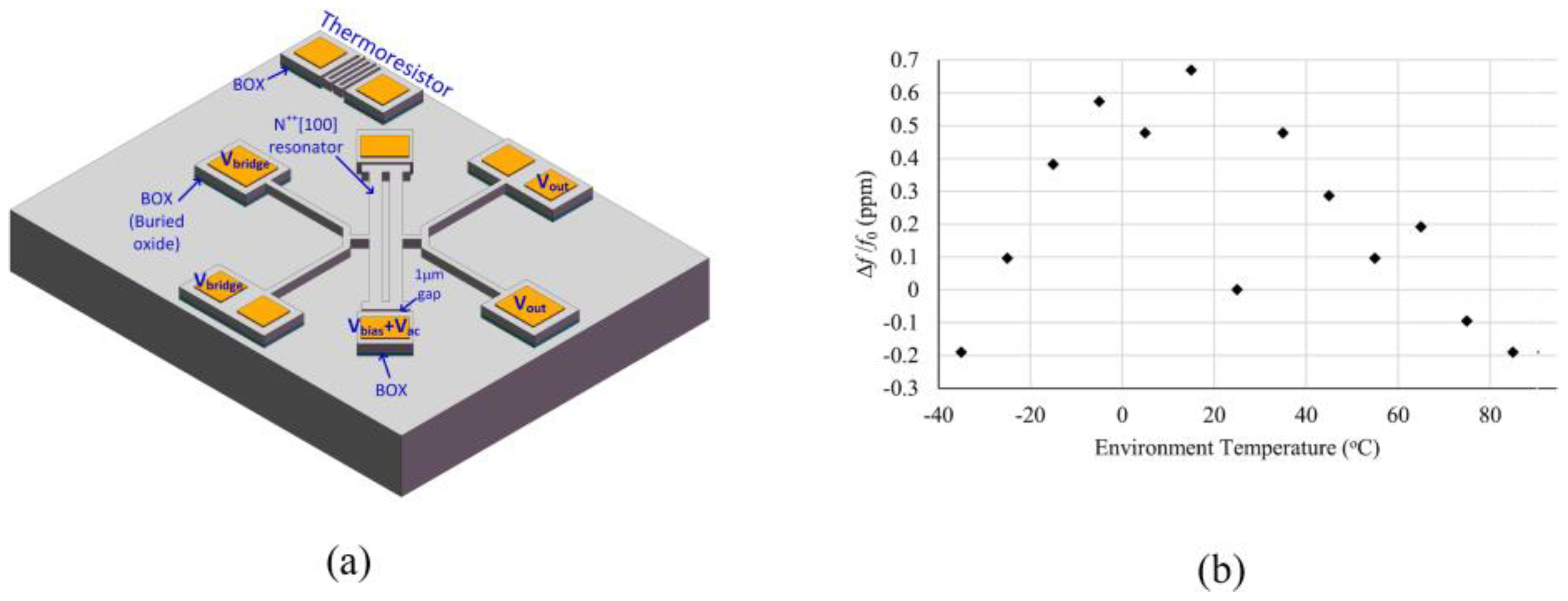
| 10 | Length-extensional | Doping and control | [128] | ±0.5 ppm −35 °C to 85 °C |
| 13 | Lamé | Doping and control | [133] | ±5 ppb −40 °C to 40 °C |
| 42.7 | Shear mode | Doping and control | [130] | ±0.4 ppm −40 °C to 80 °C |
Publisher’s Note: MDPI stays neutral with regard to jurisdictional claims in published maps and institutional affiliations. |
© 2022 by the authors. Licensee MDPI, Basel, Switzerland. This article is an open access article distributed under the terms and conditions of the Creative Commons Attribution (CC BY) license (https://creativecommons.org/licenses/by/4.0/).
Share and Cite
Feng, T.; Yuan, Q.; Yu, D.; Wu, B.; Wang, H. Concepts and Key Technologies of Microelectromechanical Systems Resonators. Micromachines 2022, 13, 2195. https://doi.org/10.3390/mi13122195
Feng T, Yuan Q, Yu D, Wu B, Wang H. Concepts and Key Technologies of Microelectromechanical Systems Resonators. Micromachines. 2022; 13(12):2195. https://doi.org/10.3390/mi13122195
Chicago/Turabian StyleFeng, Tianren, Quan Yuan, Duli Yu, Bo Wu, and Hui Wang. 2022. "Concepts and Key Technologies of Microelectromechanical Systems Resonators" Micromachines 13, no. 12: 2195. https://doi.org/10.3390/mi13122195