
Fuzzy Control Modeling to Optimize the Hardness and Geometry of Laser Cladded Fe-Based MG Single Track on Stainless Steel Substrate Prepared at Different Surface Roughness
 , ,
, ,  and
and
Abstract
:1. Introduction
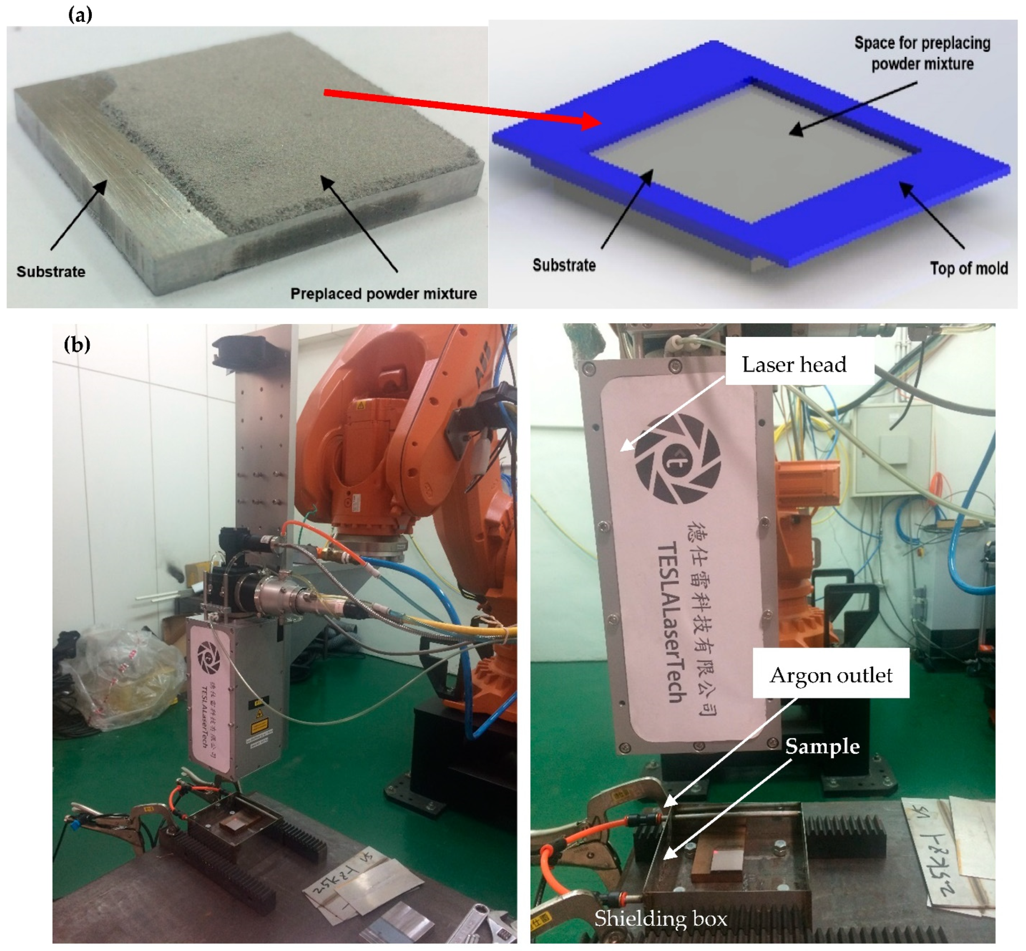
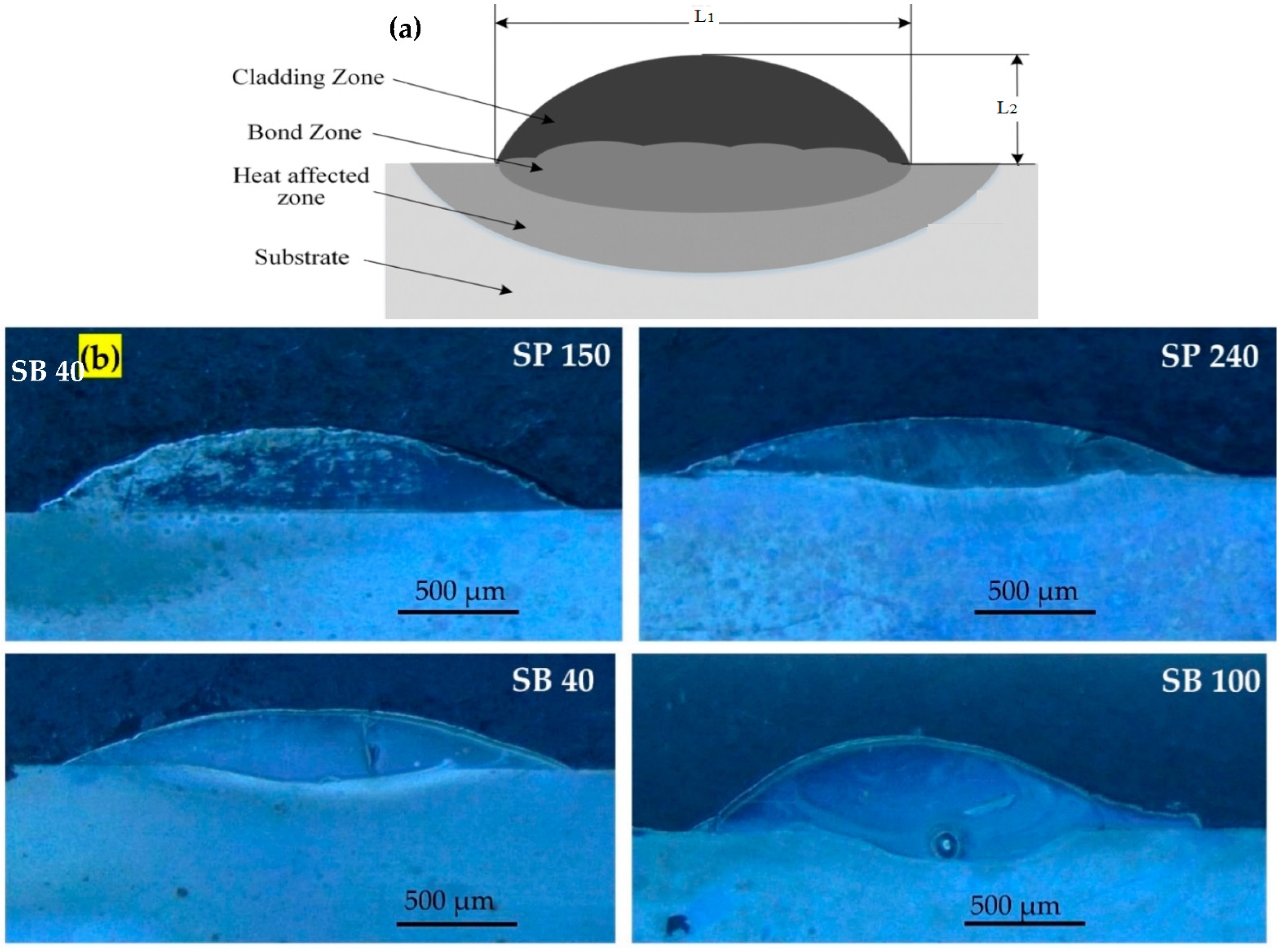
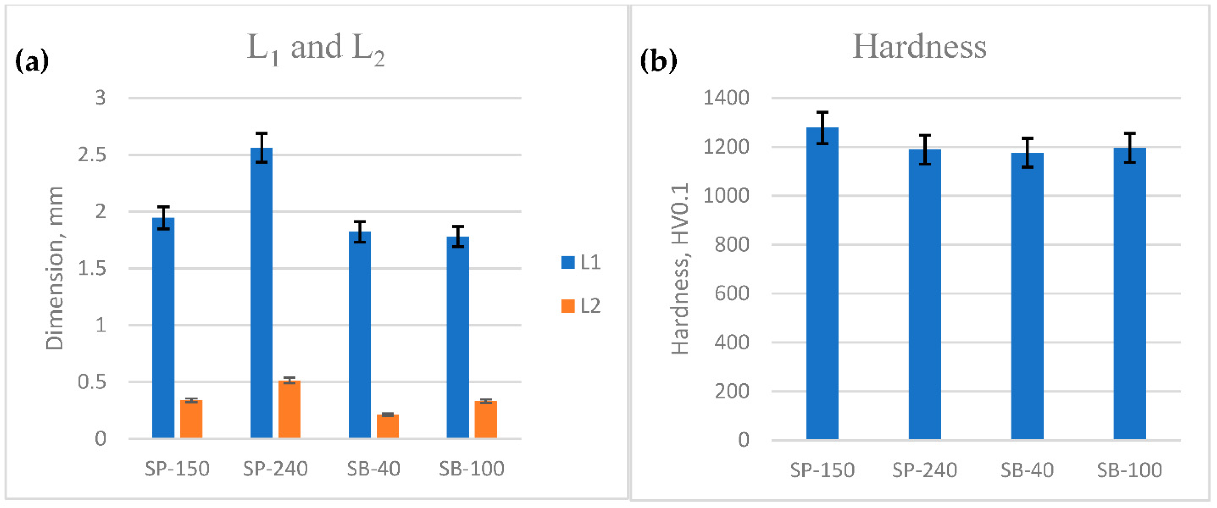
2. Laser Cladding of Fe-Based MG
3. Fuzzy Logic Controller (FLC)
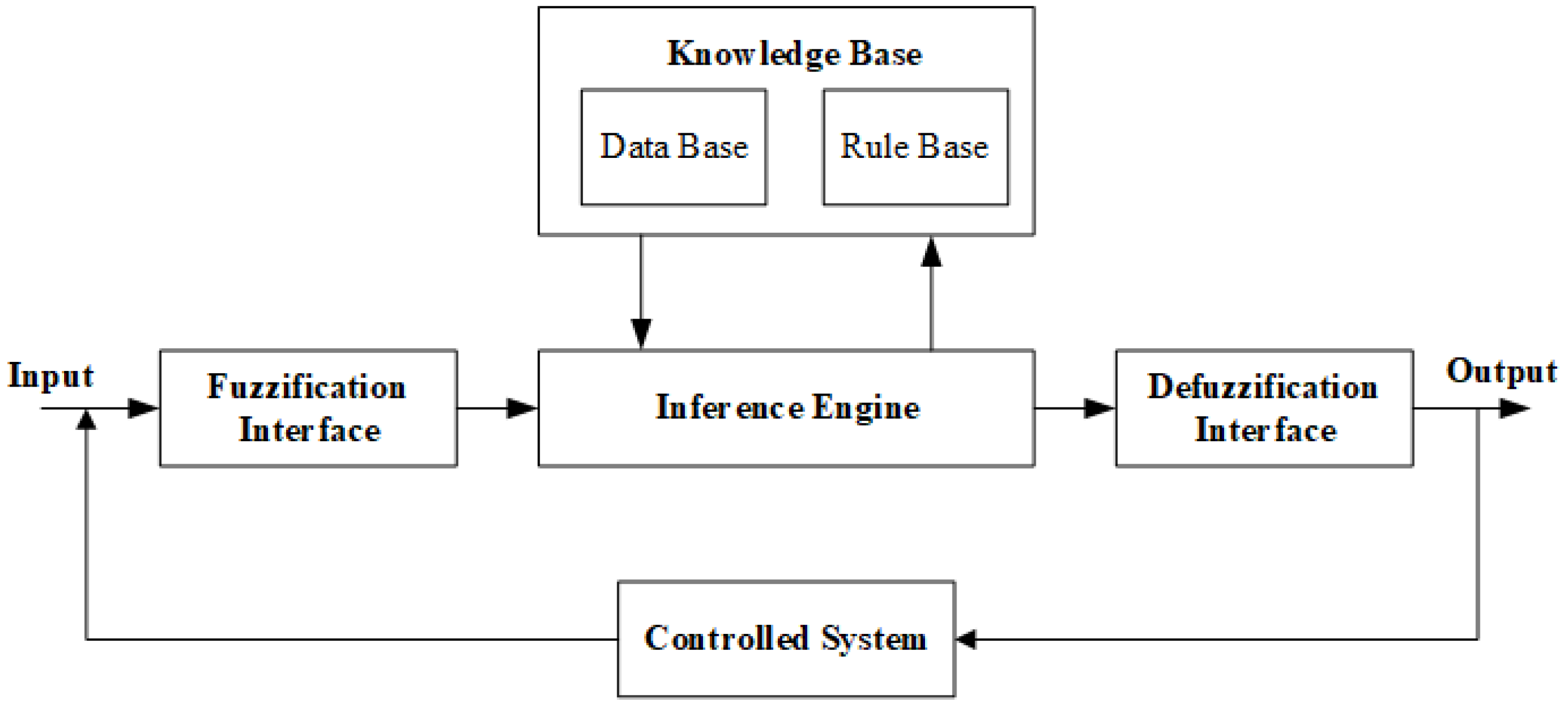
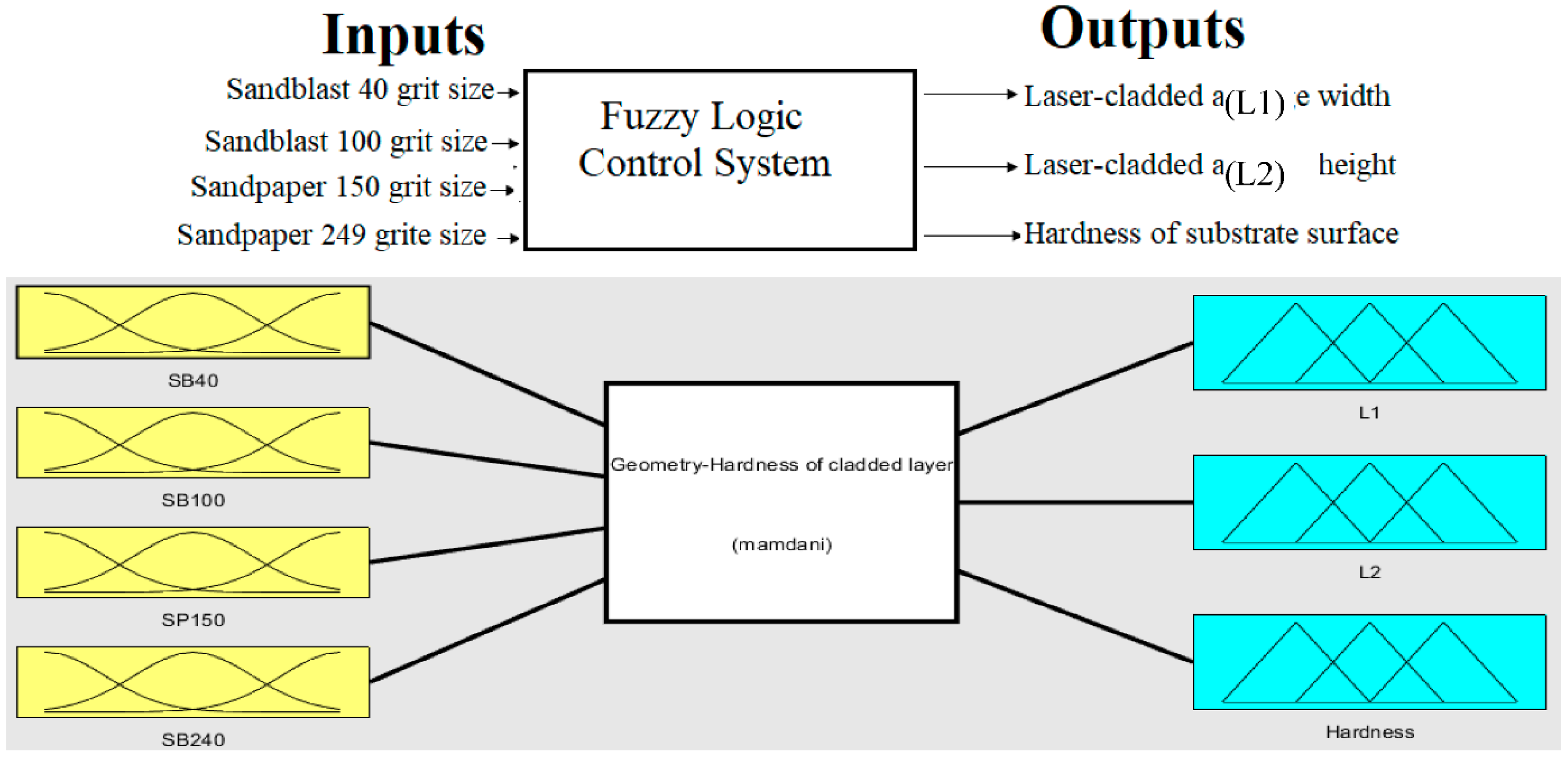
3.1. Architecture of Fuzzy Logic Controller
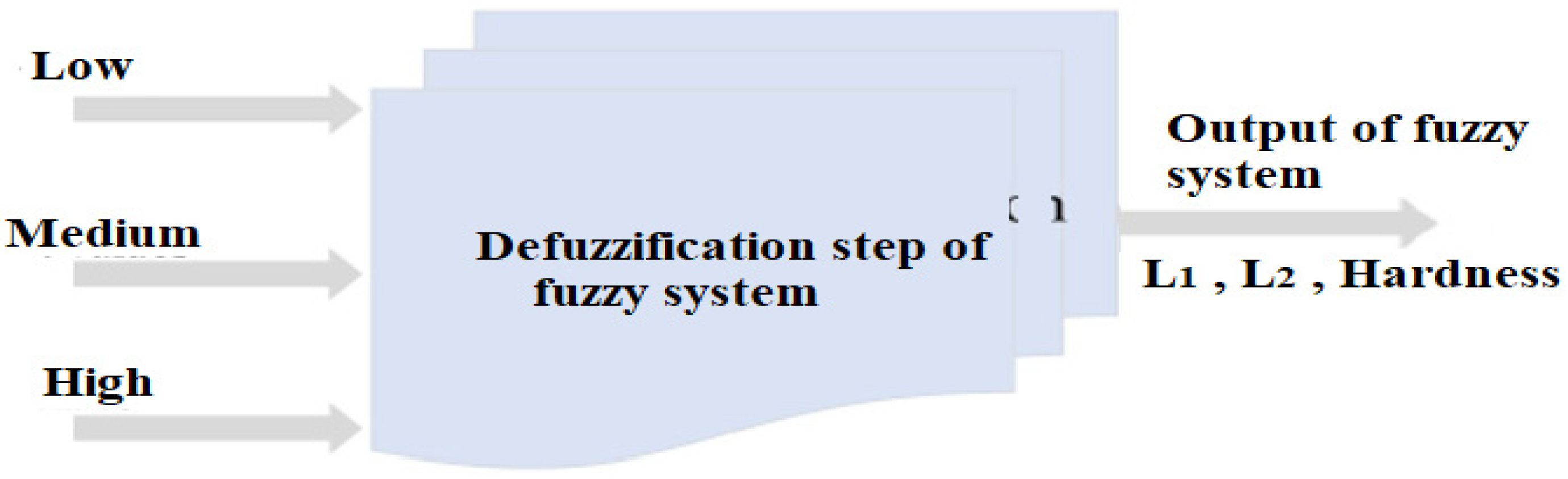
3.2. Inputs and Output Fuzzy System Variables
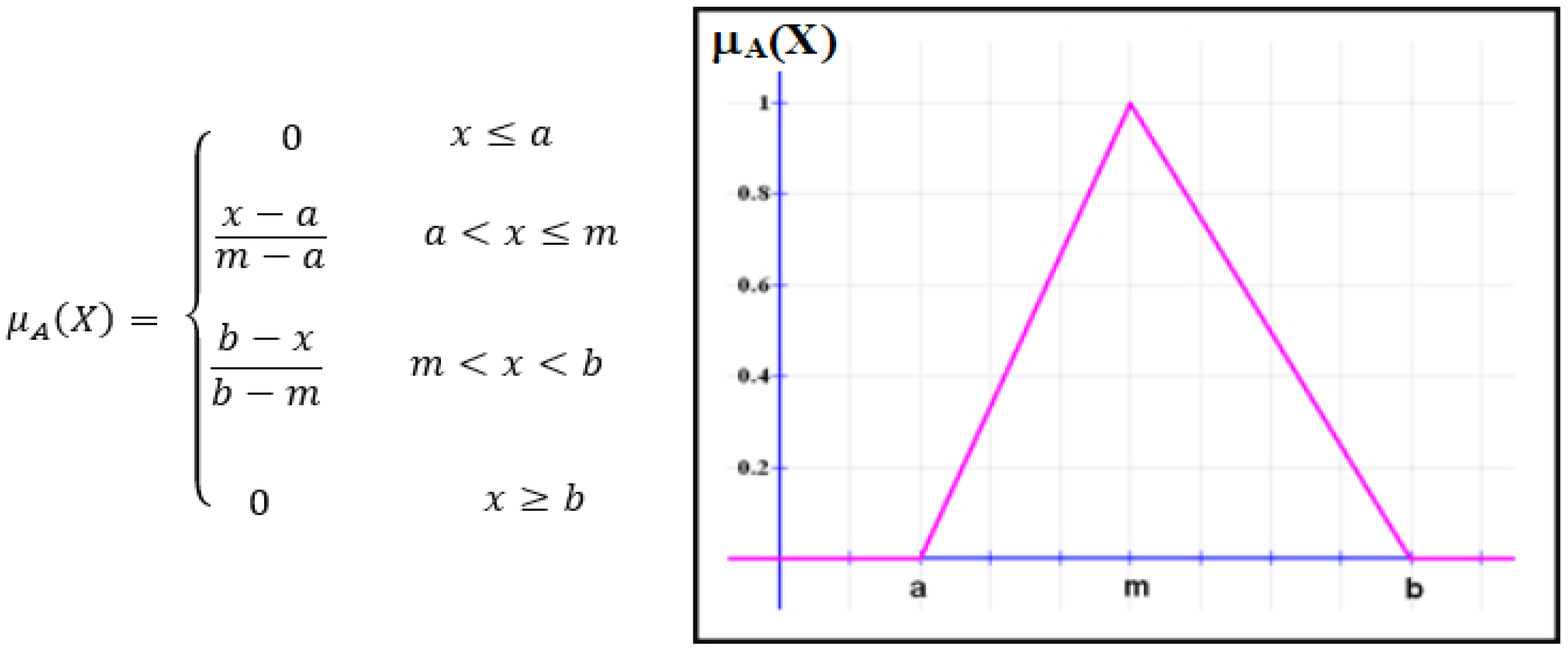
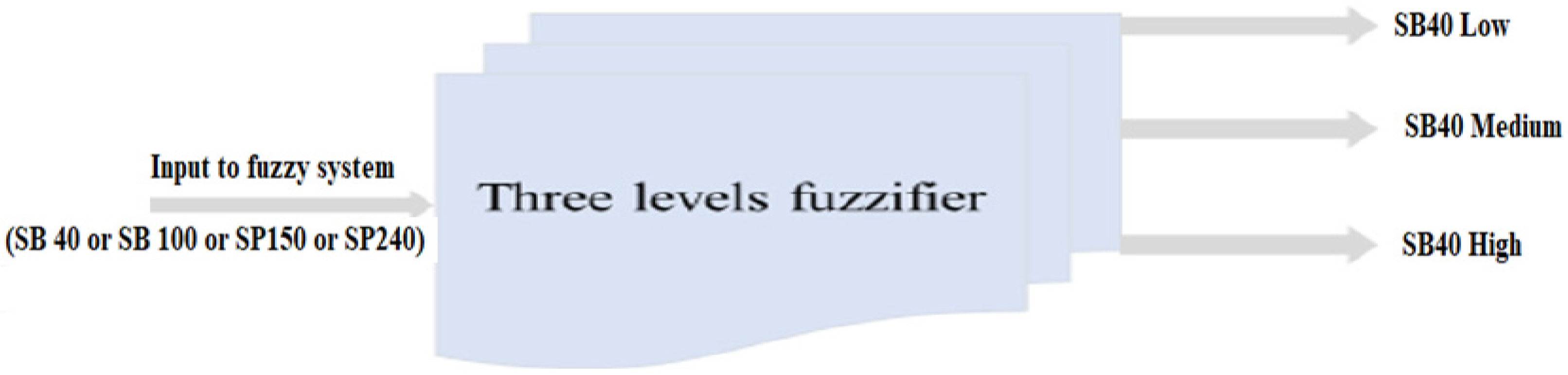
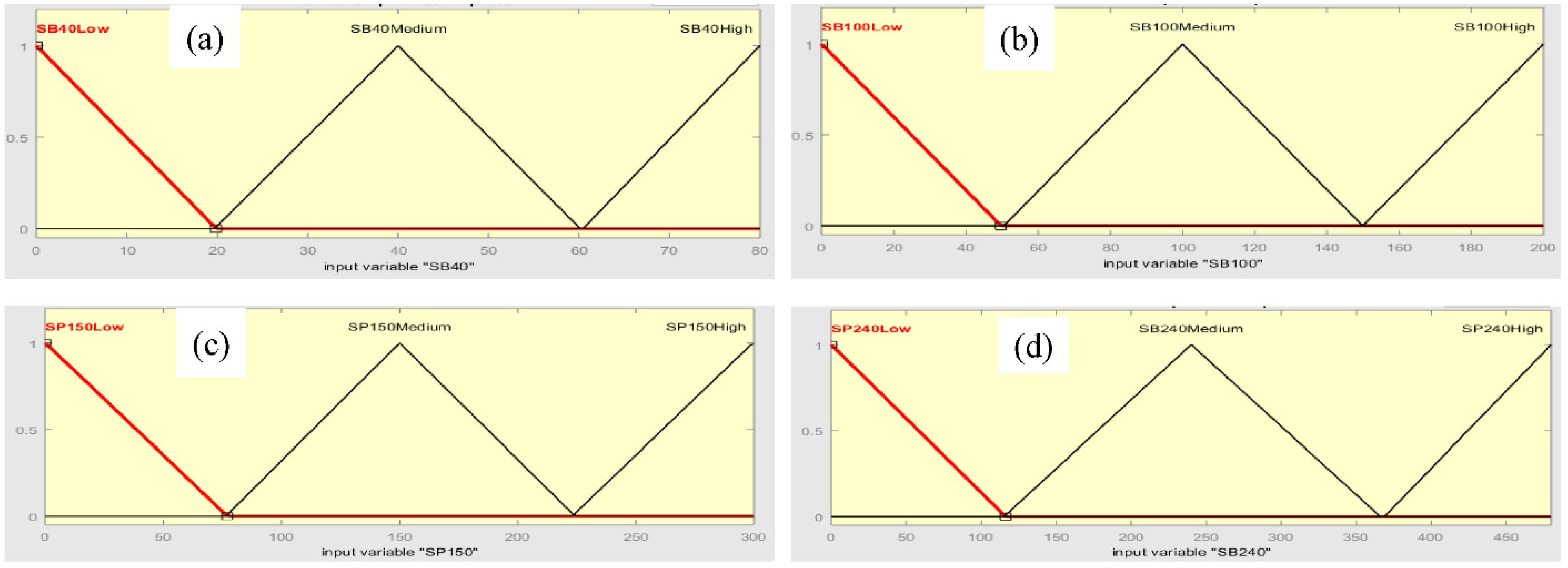
3.3. Inputs and Outputs Membership Function
3.4. FLC Base Rules
4. Conclusions
Author Contributions
Funding
Data Availability Statement
Acknowledgments
Conflicts of Interest
References
- Siddiqui, A.A.; Dubey, A.K. Recent trends in laser cladding and surface alloying. Opt. Laser Technol. 2021, 134, 106619. [Google Scholar] [CrossRef]
- Bourahima, F.; Helbert, A.L.; Rege, M.; Ji, V.; Solas, D.; Baudin, T. Laser cladding of Ni based powder on a Cu-Ni-Al glassmold: Influence of the process parameters on bonding quality and coating geometry. J. Alloys Compd. 2019, 771, 1018–1028. [Google Scholar] [CrossRef] [Green Version]
- Zeng, C.; Tian, W.; Liao, W.H.; Hua, L.; He, W.; Hua, L. Microstructure and porosity evaluation in laser-cladding deposited Ni-based coatings. Surf. Coat. Technol. 2016, 294, 122–130. [Google Scholar] [CrossRef]
- Comesaña, R.; Quintero, F.; Lusquiños, F.; Pascual, M.J.; Boutinguiza, M.; Durán, A.; Pou, J. Laser cladding of bioactive glass coatings. Acta Biomater. 2010, 6, 953–961. [Google Scholar] [CrossRef]
- Penide, J.; Lusqui, F.; Quintero, F.; Riveiro, A.; Boutinguiza, M.; Pou, J.; Arias-González, F.; del Val, J.; Comesaña, R.; Penide, J.; et al. Fiber laser cladding of nickel-based alloy on cast iron. Appl. Surf. Sci. 2016, 374, 197–205. [Google Scholar] [CrossRef]
- Li, Y. Laser Cladding of Alumina Material Coating: Effects on Deposition Quality. In Proceedings of the ASME 2016 11th International Manufacturing Science and Engineering Conference, Blacksburg, VA, USA, 27 June–1 July 2017; pp. 1–7. [Google Scholar]
- Gao, Y.-L.; Shen, J.; Sun, J.-F.; Wang, G.; Xing, D.-W.; Xian, H.-Z.; Zhou, B.-D. Crystallization behavior of ZrAlNiCu bulk metallic glass with wide supercooled liquid region. Mater. Lett. 2003, 57, 1894–1898. [Google Scholar] [CrossRef]
- Suryanarayana, C.; Inoue, A. Iron-based bulk metallic glasses. Int. Mater. Rev. 2013, 58, 131–166. [Google Scholar] [CrossRef]
- Maddala, D.R.; Mubarok, A.; Hebert, R.J. Sliding wear behavior of Cu50Hf41.5Al8.5 bulk metallic glass. Wear 2010, 269, 572–580. [Google Scholar] [CrossRef]
- Williams, E.; Lavery, N. Laser processing of bulk metallic glass: A review. J. Mater. Process. Technol. 2017, 247, 73–91. [Google Scholar] [CrossRef] [Green Version]
- Yanfang, W.; Qinglong, L.; Lijun, X.; Zhiqiang, S. Laser Cladding Fe-Cr-Si-P Amorphous Coatings on 304L Stainless. Rare Met. Mater. Eng. 2014, 43, 274–277. [Google Scholar] [CrossRef]
- Zhang, W.; Tao, P.; Tu, Q.; Li, D.; Yang, Y. Effect of laser surface melting on bulk metallic glass: Investigation of microstructure, microhardness, friction and wear properties. J. Alloys Compd. 2017, 732, 792–798. [Google Scholar] [CrossRef]
- Ibrahim, M.Z.; Sarhan, A.D.; Shaikh, M.O.; Kuo, T.Y.; Yusuf, F.; Hamdi, M. Investigate the effects of the laser cladding parameters on the microstructure, phases formation, mechanical and corrosion properties of metallic glasses coatings for biomedical implant application. In Additive Manufacturing of Emerging Materials; Springer: Berlin/Heidelberg, Germany, 2019; pp. 299–323. ISBN 978-3-319-91712-2. [Google Scholar]
- Wu, X.L.; Hong, Y.S. Microstructure of Zr-alloyed coating using pulsed laser. Surf. Coat. Technol. 2000, 132, 194–197. [Google Scholar] [CrossRef]
- Li, R.; Jin, Y.; Li, Z.; Zhu, Y.; Wu, M. Effect of the remelting scanning speed on the amorphous forming ability of Ni-based alloy using laser cladding plus a laser remelting process. Surf. Coat. Technol. 2014, 259, 725–731. [Google Scholar] [CrossRef]
- Liu, H.; Qin, X.; Huang, S.; Hu, Z.; Ni, M. Geometry modeling of single track cladding deposited by high power diode laser with rectangular beam spot. Opt. Lasers Eng. 2018, 100, 38–46. [Google Scholar] [CrossRef]
- Ibrahim, M.Z.; Sarhan, A.A.D.; Kuo, T.Y.; Yusuf, F.; Hamdi, M.; Chien, C.S. Investigate the effects of the substrate surface roughness on the geometry, phase transformation, and hardness of laser-cladded Fe-based metallic glass coating. Int. J. Adv. Manuf. Technol. 2018, 98, 1977–1987. [Google Scholar] [CrossRef]
- Singh, N.; Hameed, P.; Ummethala, R.; Manivasagam, G.; Prashanth, K.G.; Eckert, J. Selective laser manufacturing of Ti-based alloys and composites: Impact of process parameters, application trends, and future prospects. Mater. Today Adv. 2020, 8, 100097. [Google Scholar] [CrossRef]
- Shamsaei, N.; Yadollahi, A.; Bian, L.; Thompson, S.M. An overview of Direct Laser Deposition for additive manufacturing; Part II: Mechanical behavior, process parameter optimization and control. Addit. Manuf. 2015, 8, 12–35. [Google Scholar] [CrossRef]
- Tamanna, N.; Crouch, R.; Naher, S. Progress in numerical simulation of the laser cladding process. Opt. Lasers Eng. 2019, 122, 151–163. [Google Scholar] [CrossRef]
- Bakhtiyari, A.N.; Wang, Z.; Wang, L.; Zheng, H. A review on applications of artificial intelligence in modeling and optimization of laser beam machining. Opt. Laser Technol. 2021, 135, 106721. [Google Scholar] [CrossRef]
- Klement, E.P.; Slany, W. Fuzzy Logic in Artifcial Intelligence, Vienna. In Proceedings of the 8th Austrian Artificial Intelligence Conference, FLAI’93, Linz, Austria, 28–30 June 1993. [Google Scholar]
- Yager, R.R. Fuzzy logics and artificial intelligence. Fuzzy Sets Syst. 1997, 90, 193–198. [Google Scholar] [CrossRef]
- Precup, R.E.; Hellendoorn, H. A survey on industrial applications of fuzzy control. Comput. Ind. 2011, 62, 213–226. [Google Scholar] [CrossRef]
- Kavka, C.; Roggero, P.; Apolloni, J. An Architecture for Fuzzy Logic Controllers Evolution and Learning in Microcontroller based Environments. In Proceedings of the IX Congreso Argentino de Ciencias de la Computación, La Plata, Argentina, 6–10 October 2003; pp. 530–541. [Google Scholar]
- Zalnezhad, E.; Sarhan, A.A.D.; Hamdi, M. A fuzzy logic based model to predict surface hardness of thin film TiN coating on aerospace AL7075-T6 alloy. Int. J. Adv. Manuf. Technol. 2013, 68, 415–423. [Google Scholar] [CrossRef]
- Zalnezhad, E.; Sarhan, A.A.D. A fuzzy logic predictive model for better surface roughness of Ti-TiN coating on AL7075-T6 alloy for longer fretting fatigue life. Meas. J. Int. Meas. Confed. 2014, 49, 256–265. [Google Scholar] [CrossRef]
- Zeinali, M.; Khajepour, A. Development of an adaptive fuzzy logic-based inverse dynamic model for laser cladding process. Eng. Appl. Artif. Intell. 2010, 23, 1408–1419. [Google Scholar] [CrossRef]
- Sohrabpoor, H. Perspective of Applying Adaptive Neuro Fuzzy Inference System (ANFIS) in Laser Cladding of Graphene-Metal Alloys Predictive quality modeling of polymer and metal parts fabricated by SLS and SLM additive manufacturing processes View project. J. Nanotechnol. 2017, 4, 017. [Google Scholar] [CrossRef] [Green Version]
- Nair, A.; Ramji, V.; Durai Raj, R.; Veeramani, R. Laser cladding of Stellite 6 on EN8 steel—A fuzzy modelling approach. Mater. Today Proc. 2020, 39, 348–353. [Google Scholar] [CrossRef]
- Grieve, D.J.; Kaliszer, H.; Rowe, G.W. The effects of cutting conditions on bearing area parameters. In Proceedings of the 9th International Machine Tool Design and Research Conference, UK, September 1968; Volume 2, pp. 989–1004. [Google Scholar]
- Wang, X.; Feng, C.X. Development of Empirical Models for Surface Roughness Prediction in Finish Turning. Int. J. Adv. Manuf. Technol. 2002, 20, 348–356. [Google Scholar] [CrossRef]
- Fischer, H.L.; Elrod, J.T. Surface finish as a function of tool geometry and feed—A theoretical approach. Microtecnic 1971, 25, 175–178. [Google Scholar]
- Sundarain, R.M.; Lanibeil, B.K. Mathematical models to predict surface finish in fine turning of steel, Pans I and II. Int. J. Prod. Res. 1981, 19, 547–564. [Google Scholar] [CrossRef]
- Hascgawa, H.; Seireg, A.; Lindberg, R.A. Surface roughness model for turning. Tribology 1976, 9, 285–289. [Google Scholar] [CrossRef]
- Miller, J.C.; de Vor, R.E.; Southerland, J.W. Surface roughness characteristics for turning 380 and 390 aluminum casting alloys. In Proceedings of the North American Manufacturing Research Conference, Madison, WI, USA, 24–26 May 1983; pp. 282–288. [Google Scholar]
- Daroonparvar, M.; Bakhsheshi-Rad, H.R.; Saberi, A.; Razzaghi, M.; Kasar, A.K.; Ramakrishna, S.; Menezes, P.L.; Misra, M.; Ismail, A.F.; Sharif, S.; et al. Surface modification of magnesium alloys using thermal and solid-state cold spray processes: Challenges and latest progresses. J. Magnes. Alloy. 2022, 10, 2025–2061. [Google Scholar] [CrossRef]
- John, M.; Kuruveri, U.B.; Menezes, P.L. Laser Cladding-Based Surface Modification of Carbon Steel and High-Alloy Steel for Extreme Condition Applications. Coatings 2022, 12, 1444. [Google Scholar] [CrossRef]
- Qu, M.; Liang, T.; Hou, J.; Liu, Z.; Yang, E.; Liu, X. Laboratory study and field application of amphiphilic molybdenum disulfide nanosheets for enhanced oil recovery. J. Pet. Sci. Eng. 2022, 208, 109695. [Google Scholar] [CrossRef]
- Liu, H.; Coghill, G.M.; Barnes, D.P. Fuzzy qualitative trigonometry. Int. J. Approx. Reason. 2009, 51, 71–88. [Google Scholar] [CrossRef] [Green Version]
- Patyra, M.J.; Grantner, J.L. Hardware implementations of digital fuzzy logic controllers. Inf. Sci. 1999, 113, 19–54. [Google Scholar] [CrossRef]
- Adilova, N.E. Consistency of fuzzy if-then rules for control system. In Advances in Intelligent Systems and Computing; Springer: Berlin/Heidelberg, Germany, 2020; pp. 137–142. [Google Scholar] [CrossRef]
- Pedrycz, W. Why triangular membership functions? Fuzzy Sets Syst. 1994, 64, 21–30. [Google Scholar] [CrossRef]


| Material | S | P | C | Ni | Cu | Si | N | Mn | Cr | Mo | Fe |
|---|---|---|---|---|---|---|---|---|---|---|---|
| F2229 SS | 0.01 | 0.03 | 0.08 | 0.1 | 0.3 | 0.7 | >0.90 | 1.5 | 19 | 21 | Balance |
| Sample | L1, mm | L2, mm | Hardness, HV0.1 |
|---|---|---|---|
| SP-150 (Sand Paper with 150 grit) | 1.946 ± 0.110 | 0.338 ± 0.016 | 1278 |
| SP-240 (Sand Paper with 200 grit) | 2.562 ± 0.122 | 0.514 ± 0.015 | 1188 |
| SB-40 (Sand Blasting with 40 grit) | 1.822 ± 0.127 | 0.212 ± 0.008 | 1176 |
| SB-100 (Sand Blasting with 100 grit) | 1.780 ± 0.089 | 0.330 ± 0.018 | 1196 |
| Fuzzy System Inputs Variables | Membership Function Used | Range of Inputs | ||
|---|---|---|---|---|
| Low | Medium | High | ||
| Sandblast (SB 40) | Triangular MF | 0–20 | 20–60 | 60–80 |
| Sandblast (SB 100) | Triangular MF | 0–45 | 45–150 | 150–200 |
| Sandpaper (SP 150) | Triangular MF | 0–75 | 75–225 | 225–300 |
| Sandpaper (SP 240) | Triangular MF | 0–125 | 125–375 | 375–475 |
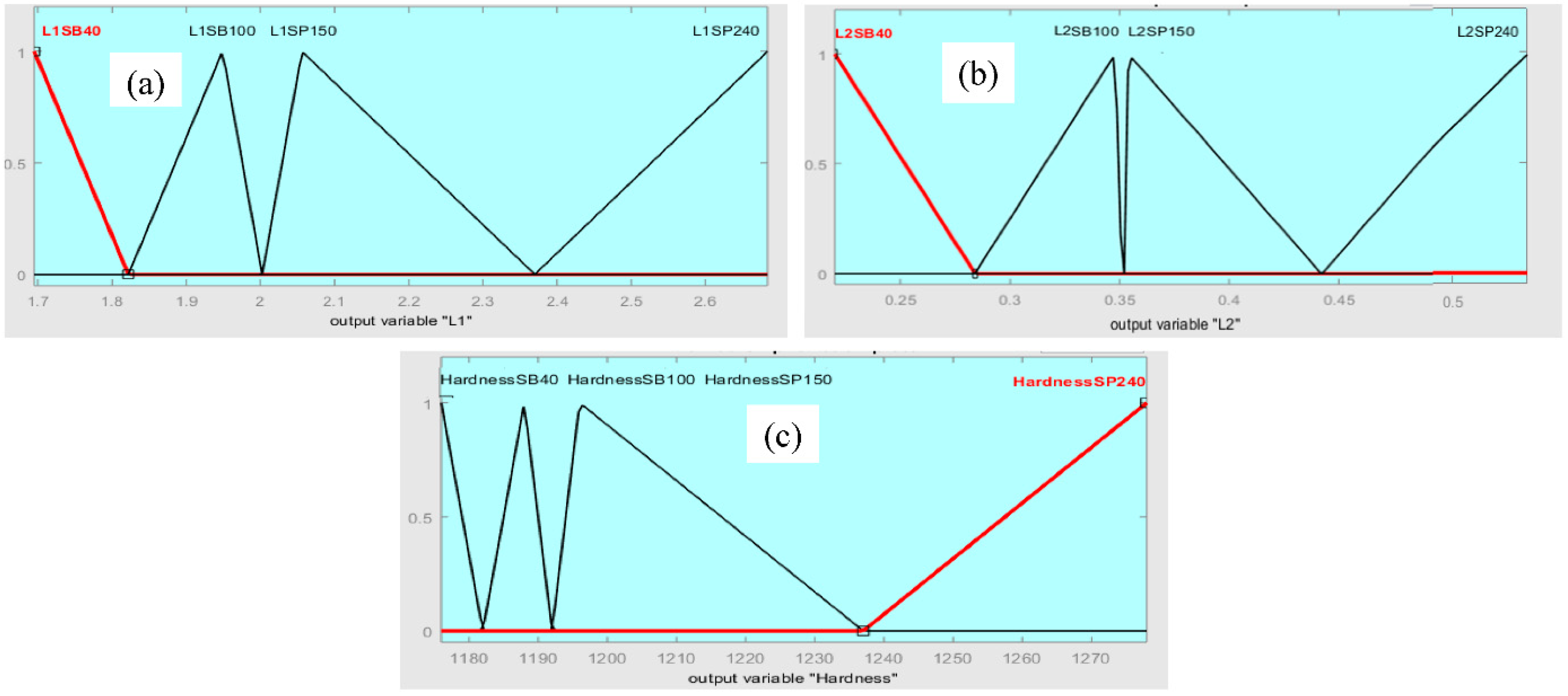
| Fuzzy System Outputs Variables | Membership Function Used | Range of Outputs | |||
|---|---|---|---|---|---|
| SB 40 | SB 100 | SP 150 | SP 240 | ||
| L1, mm | Triangular MF | 1.700–1.835 | 1.845–2.000 | 2.010–2.385 | 2.386–2.680 |
| L2, mm | Triangular MF | 0.000–0.289 | 0.290–0.350 | 0.351–0.440 | 0.450–0.610 |
| Hardness, HV0.1 | Triangular MF | 0.000–1182.0 | 1182.1–1192.0 | 1192.2–1238.0 | 1238.3–1300.0 |
| Values | Inputs | Outputs | |||||
| SB 40 | SB100 | SP 150 | SP 240 | L1, mm | L2, mm | Hardness, HV0.1 | |
| 40 | 0 | 0 | 0 | 1.73 | 0.240 | 1180 | |
| 0 | 100 | 0 | 0 | 1.92 | 0.328 | 1190 | |
| 0 | 0 | 150 | 0 | 2.05 | 0.383 | 1210 | |
| 0 | 0 | 0 | 240 | 2.11 | 0.501 | 1260 | |
| Parameters | L1, mm | L2, mm | Hardness, HV0.1 | |||
|---|---|---|---|---|---|---|
| Experimental Data | Fuzzy Result | Experimental Data | Fuzzy Result | Experimental Data | Fuzzy Result | |
| SB 40 | 1.822 ± 0.127 | 1.73 | 0.212 ± 0.008 | 0.240 | 1176 | 1180 |
| SB 100 | 1.780 ± 0.089 | 1.92 | 0.330 ± 0.018 | 0.328 | 1196 | 1190 |
| SP 150 | 1.946 ± 0.110 | 2.05 | 0.338 ± 0.016 | 0.383 | 1278 | 1210 |
| SP 240 | 2.562 ± 0.122 | 2.11 | 0.514 ± 0.015 | 0.501 | 1188 | 1260 |
Publisher’s Note: MDPI stays neutral with regard to jurisdictional claims in published maps and institutional affiliations. |
© 2022 by the authors. Licensee MDPI, Basel, Switzerland. This article is an open access article distributed under the terms and conditions of the Creative Commons Attribution (CC BY) license (https://creativecommons.org/licenses/by/4.0/).
Share and Cite
Lashin, M.M.A.; Ibrahim, M.Z.; Khan, M.I.; Guedri, K.; Saxena, K.K.; Eldin, S.M. Fuzzy Control Modeling to Optimize the Hardness and Geometry of Laser Cladded Fe-Based MG Single Track on Stainless Steel Substrate Prepared at Different Surface Roughness. Micromachines 2022, 13, 2191. https://doi.org/10.3390/mi13122191
Lashin MMA, Ibrahim MZ, Khan MI, Guedri K, Saxena KK, Eldin SM. Fuzzy Control Modeling to Optimize the Hardness and Geometry of Laser Cladded Fe-Based MG Single Track on Stainless Steel Substrate Prepared at Different Surface Roughness. Micromachines. 2022; 13(12):2191. https://doi.org/10.3390/mi13122191
Chicago/Turabian StyleLashin, Maha M. A., Mahmoud Z. Ibrahim, Muhammad Ijaz Khan, Kamel Guedri, Kuldeep K. Saxena, and Sayed M. Eldin. 2022. "Fuzzy Control Modeling to Optimize the Hardness and Geometry of Laser Cladded Fe-Based MG Single Track on Stainless Steel Substrate Prepared at Different Surface Roughness" Micromachines 13, no. 12: 2191. https://doi.org/10.3390/mi13122191