
Design and Optimization of a Micron-Scale Magnetoelectric Antenna Based on Acoustic Excitation

Abstract
:1. Introduction
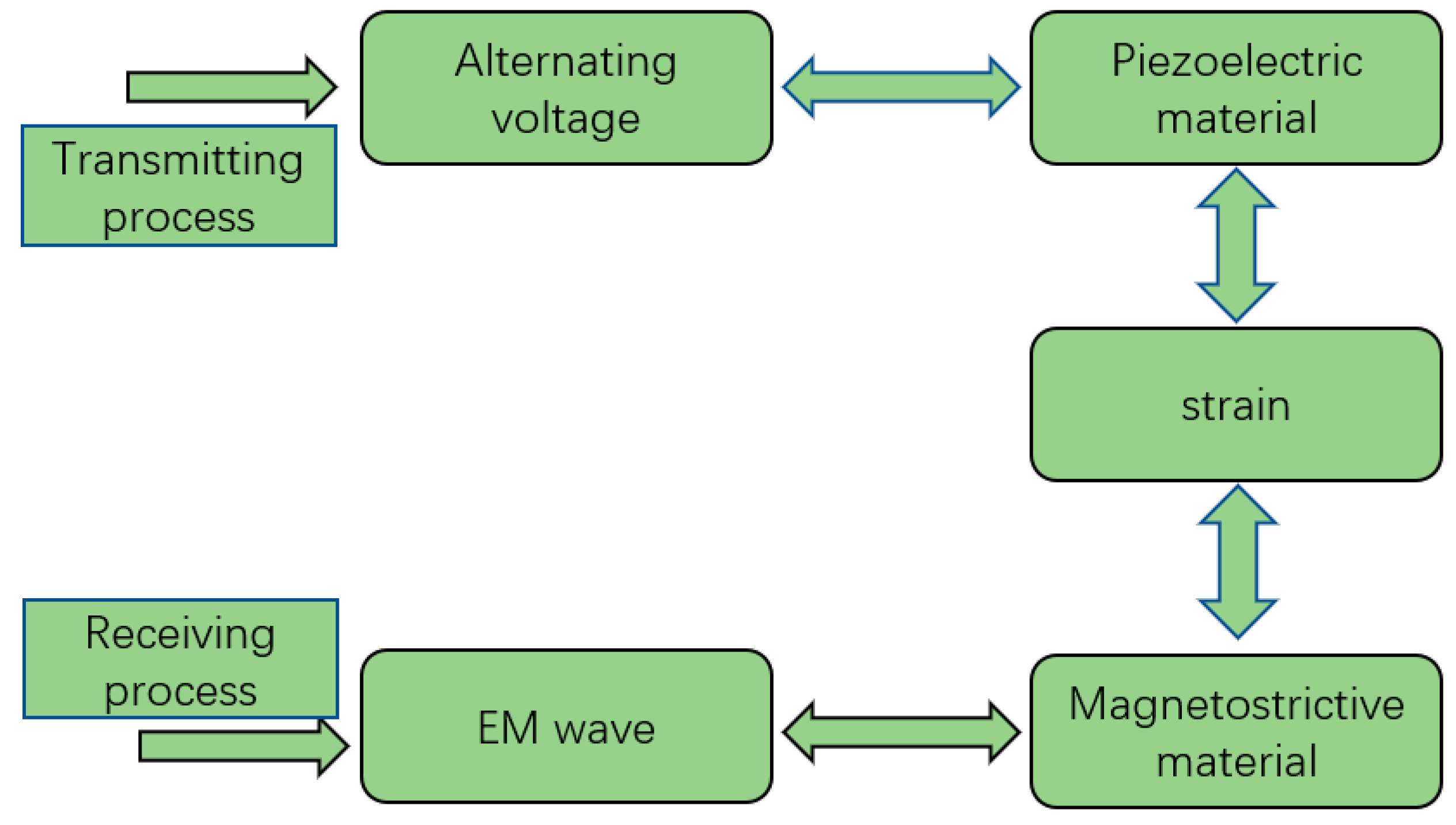
2. The Basic Principle of ME Antenna
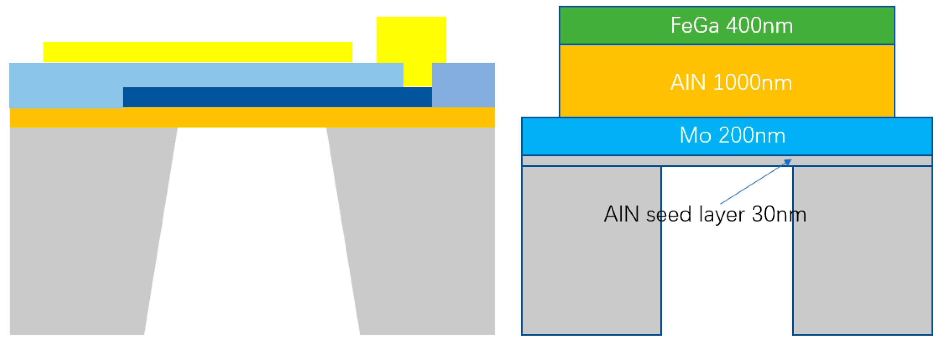
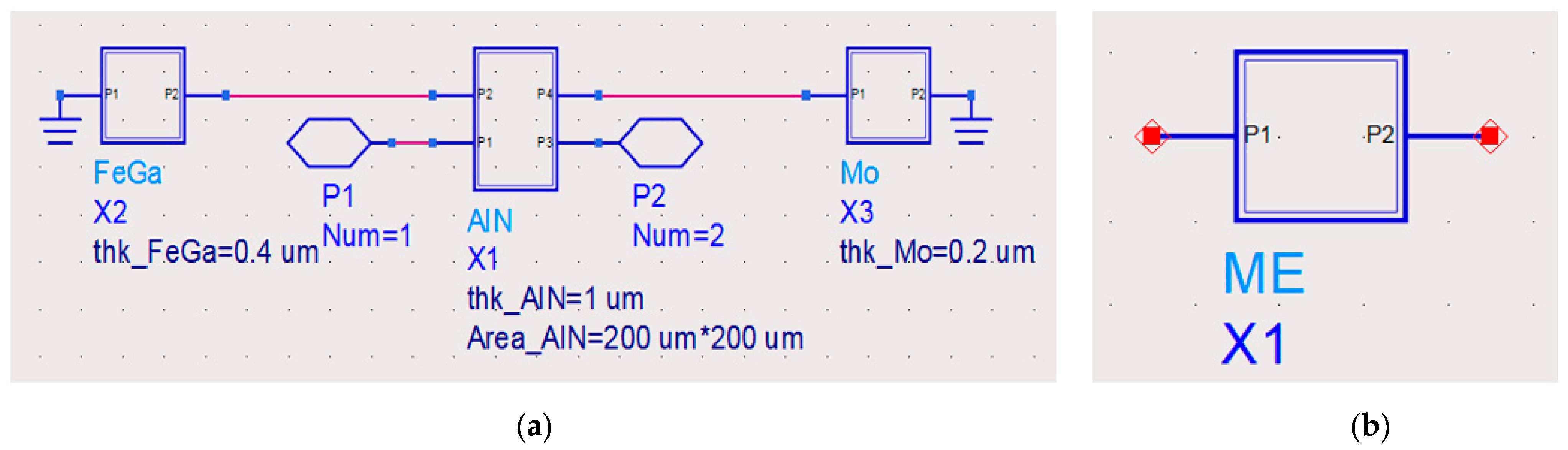
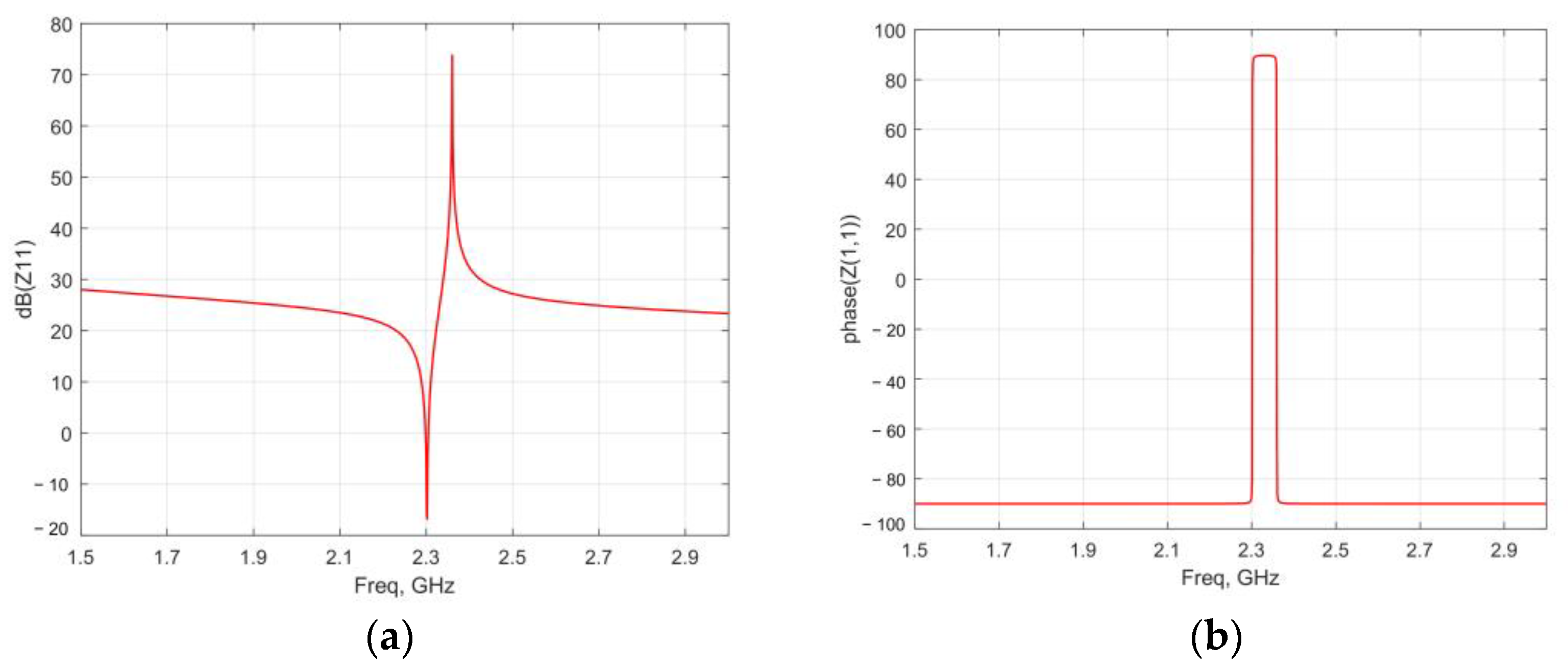
3. Design and Impedance Analysis of ME Antenna
4. Finite Element Simulation and Performance Analysis of ME Antenna
- 1.
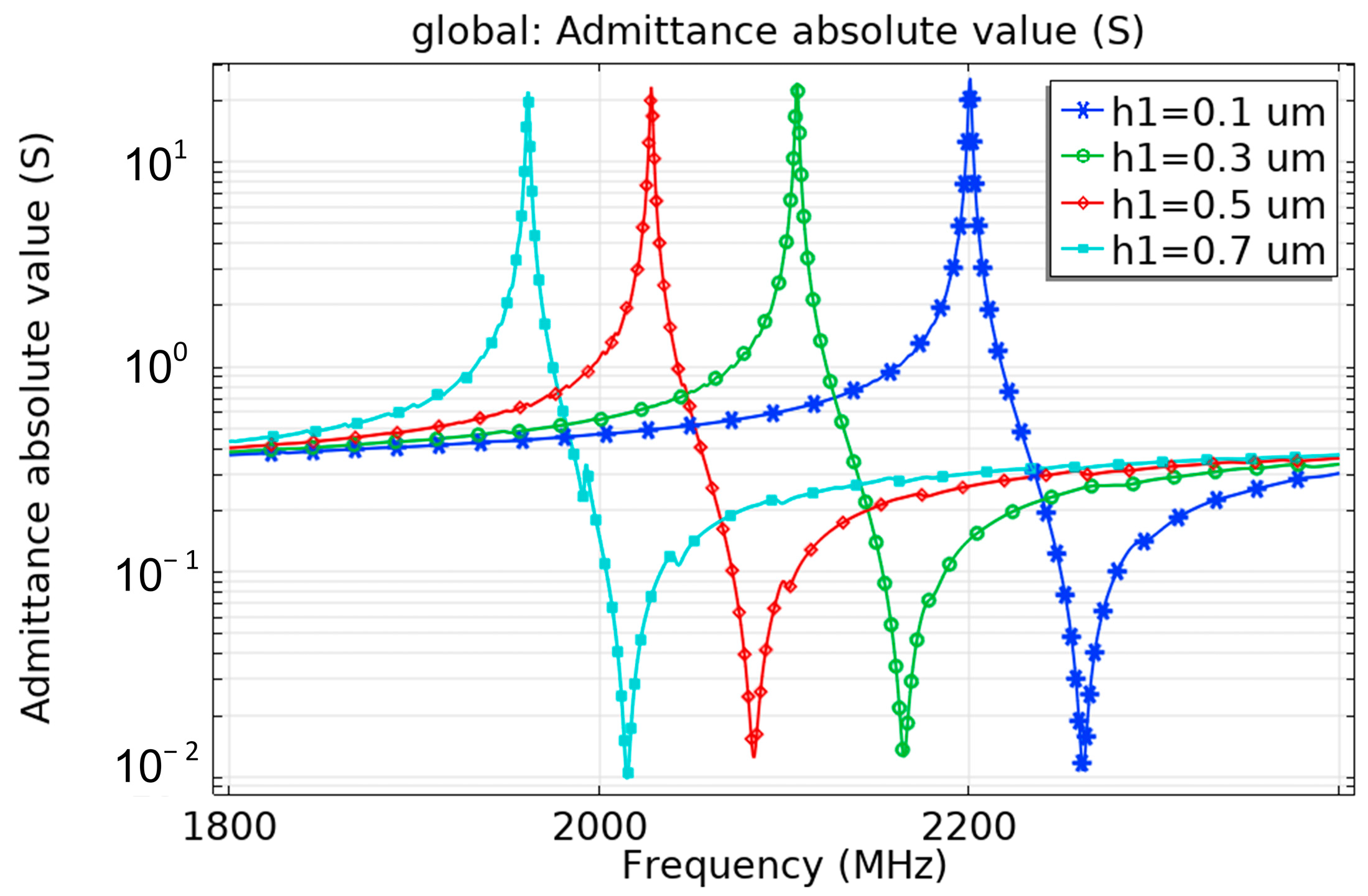
- Influence of substrate
- 2.
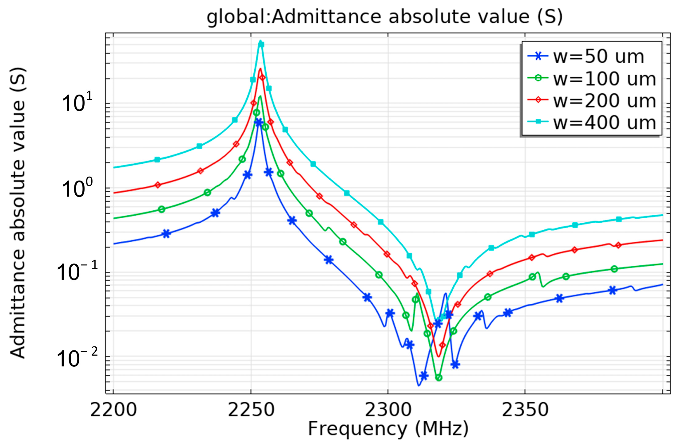
- Influence of electrode size
- 3.
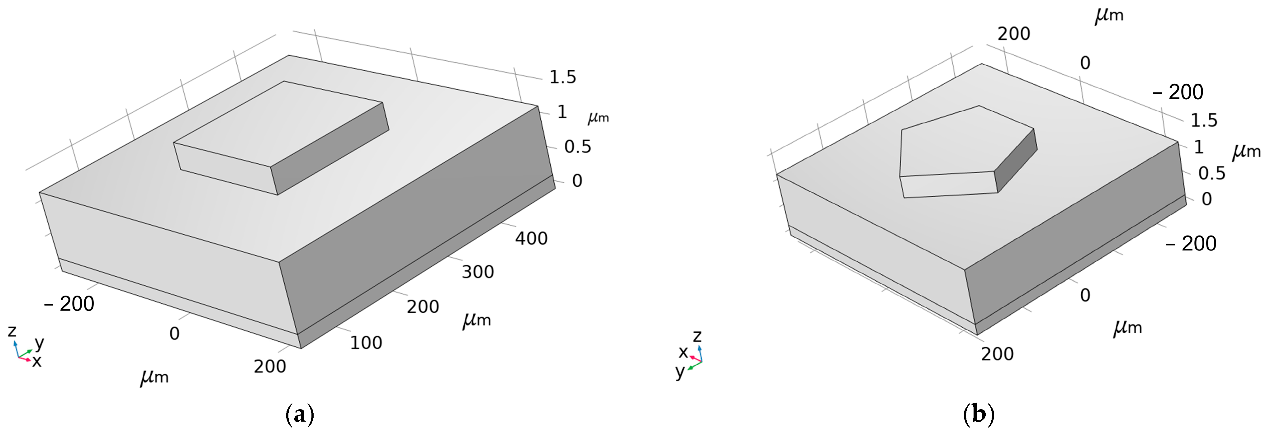
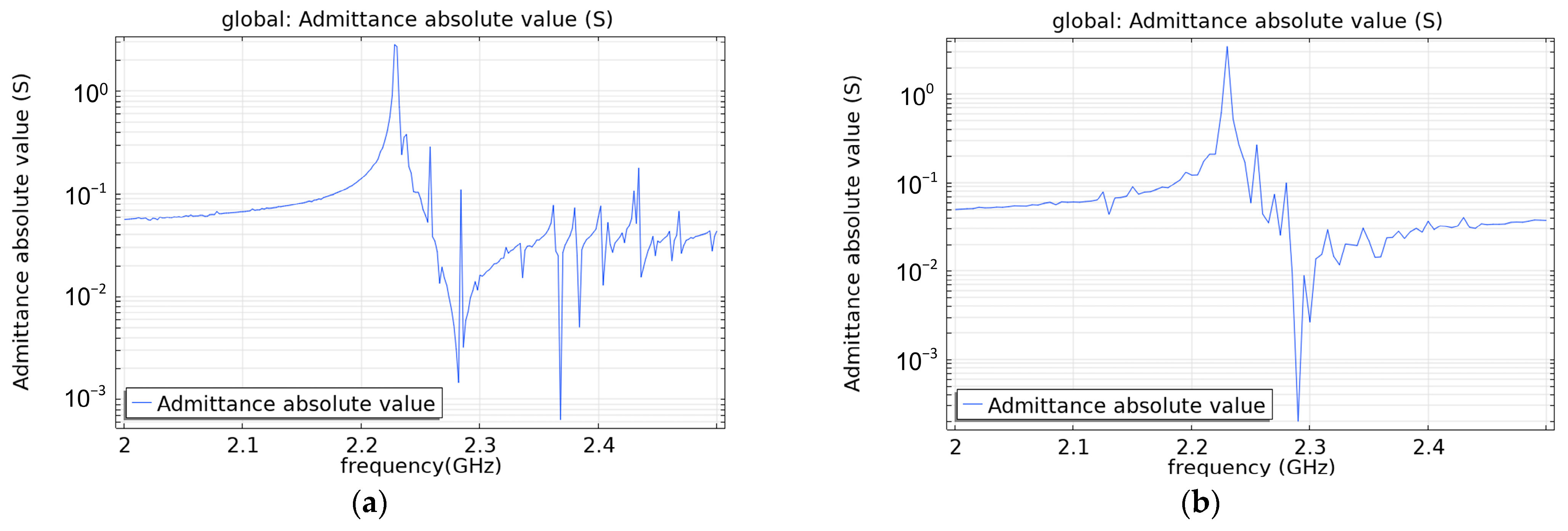
- Influence of electrode shape
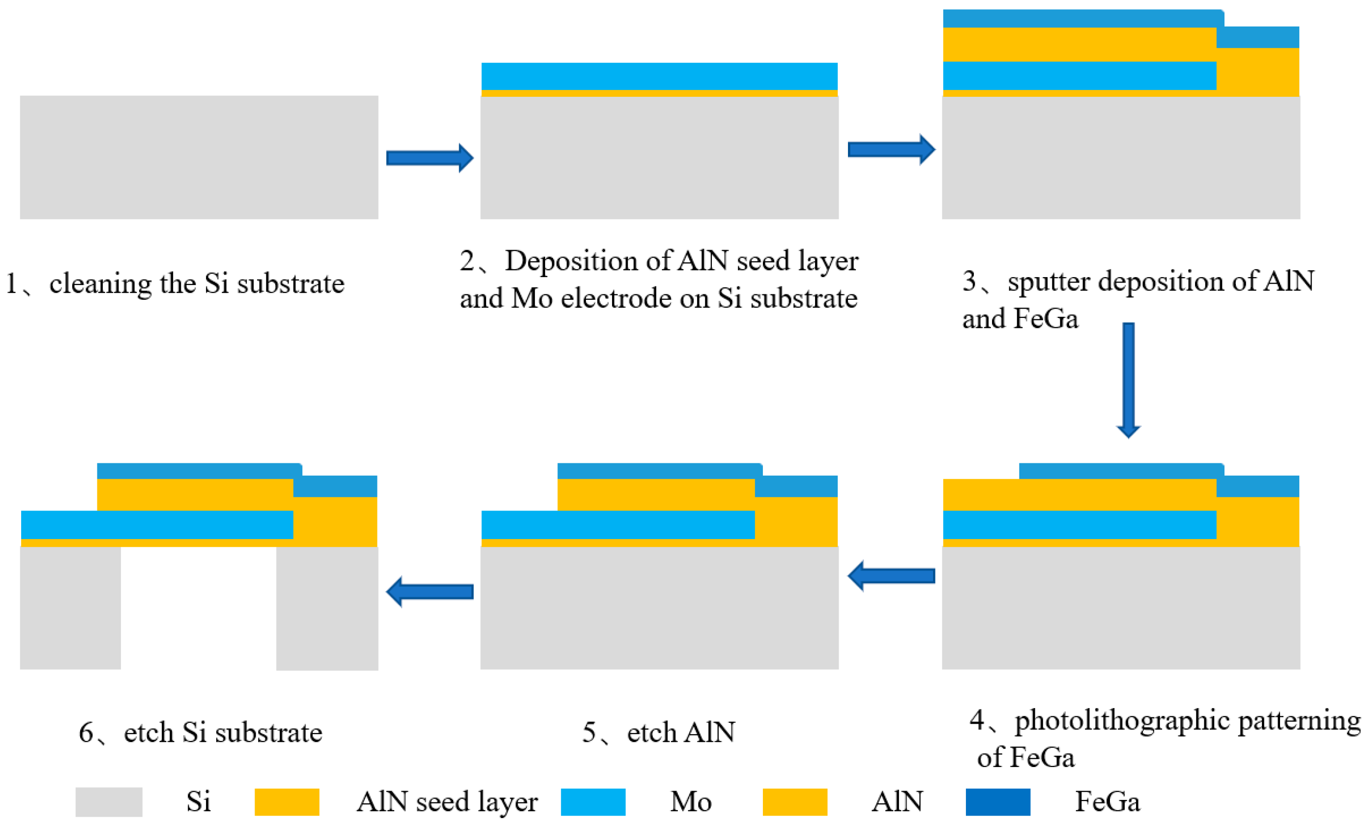
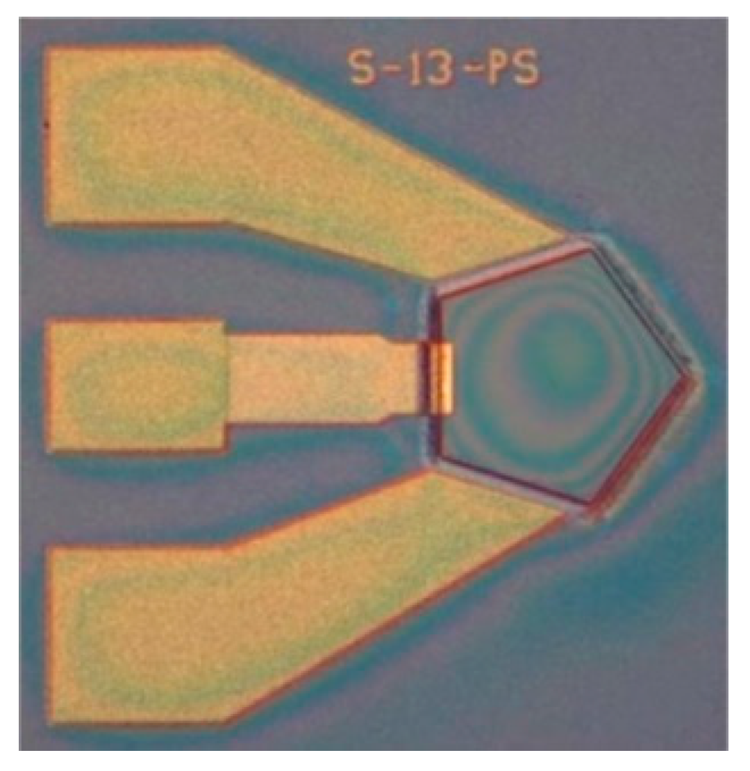
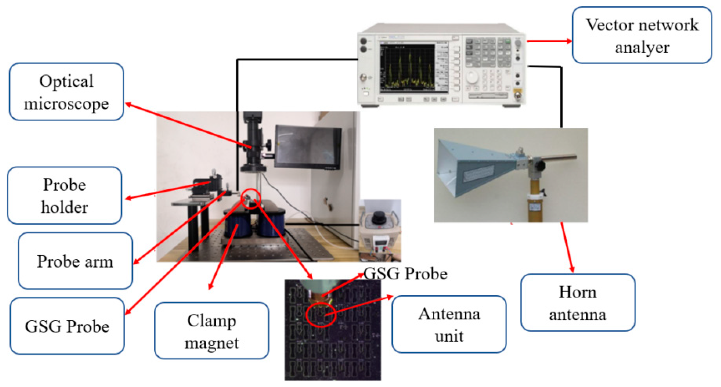
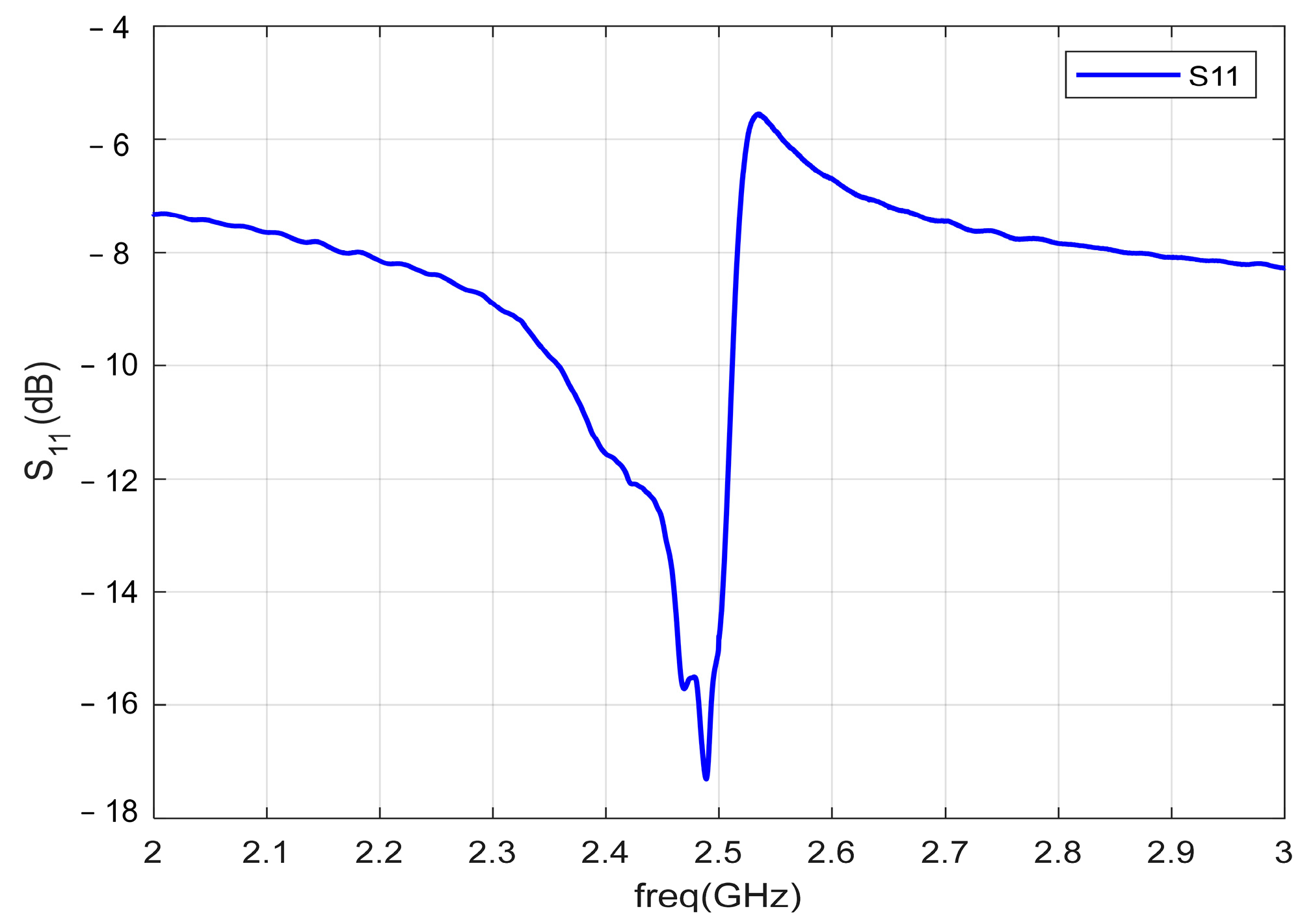
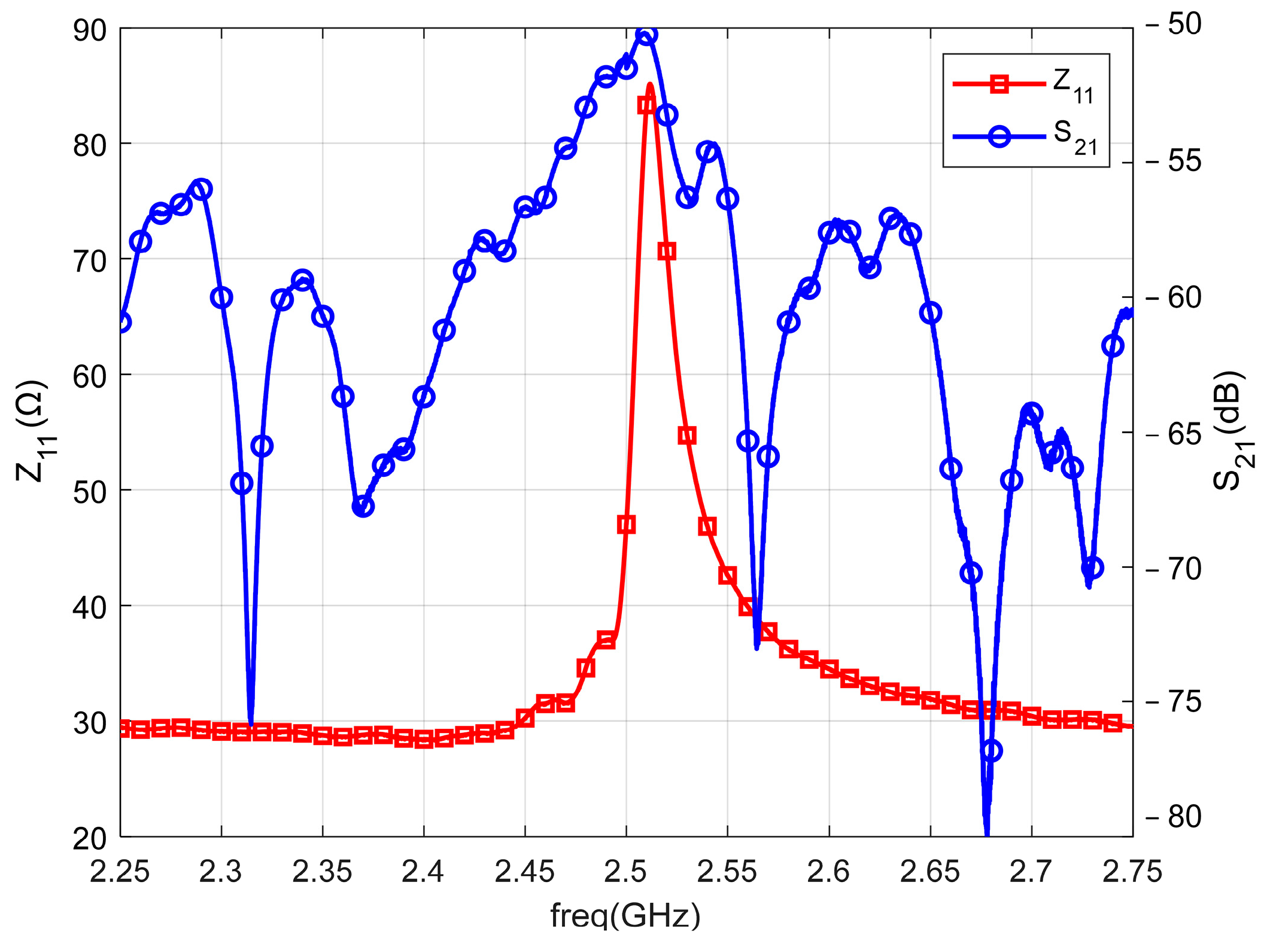
5. Fabrication and Testing of Antenna Samples
- 1.
- Calculation of Antenna Gain
- 2.
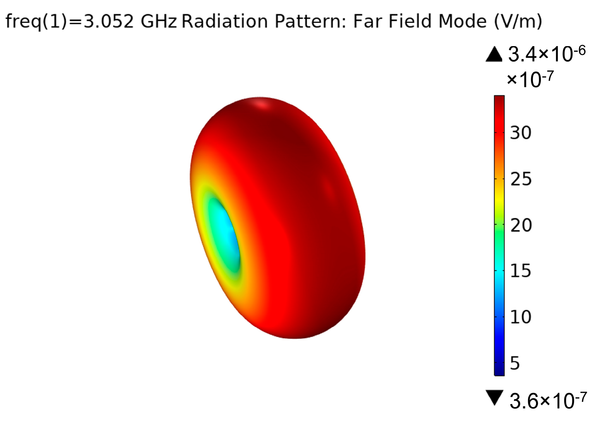
- Antenna pattern
6. Conclusions
Author Contributions
Funding
Conflicts of Interest
References
- Hansen, R.C. Fundamental limitations in antennas. Proc. IEEE 1981, 69, 170–182. [Google Scholar] [CrossRef]
- McLean, J.S. A re-examination of the fundamental limits on the radiation Q of electrically small antennas. IEEE Trans. Antennas Progag. 1996, 44, 672. [Google Scholar] [CrossRef]
- Wheeler, H.A. Fundamental limitations of small antennas. Proc. IEEE 1947, 35, 1479–1484. [Google Scholar] [CrossRef]
- Sten, J.-E.; Hujanen, A.; Koivisto, P.K. Quality factor of an electrically small antenna radiating close to a conducting plane. IEEE Trans. Antennas Progag. 2001, 49, 829–837. [Google Scholar] [CrossRef]
- Pozar, D.M. Microstrip antennas. Proc. IEEE 1992, 80, 79–81. [Google Scholar] [CrossRef]
- Yao, Z.; Wang, Y.E.; Keller, S.; Carman, G.P. Bulk Acoustic Wave-Mediated Multiferroic Antennas: Architecture and Performance Bound. IEEE Trans. Antennas Progag. 2015, 63, 3335–3344. [Google Scholar] [CrossRef]
- Domann, J.P.; Carman, G.P. Strain powered antennas. J. Appl. Phys. Lett. 2017, 121, 044905. [Google Scholar] [CrossRef]
- Nan, T.; Lin, H.; Gao, Y.; Matyushov, A.; Yu, G.; Chen, H.; Sun, N.; Wei, S.; Wang, Z.; Li, M. Acoustically actuated ultra-compact NEMS magnetoelectric antennas. Nat. Commun. 2017, 8, 296. [Google Scholar] [CrossRef]
- Hassanien, A.E.; Breen, M.; Li, M.-H.; Gong, S. A theoretical study of acoustically driven antennas. J. Appl. Phys. 2020, 127, 14903. [Google Scholar] [CrossRef]
- Bickford, J.A.; Duwel, A.E.; Weinberg, M.S.; McNabb, R.S.; Freeman, D.K.; Ward, P.A. Performance of Electrically Small Conventional and Mechanical Antennas. IEEE Trans. Antennas Progag. 2019, 67, 2209–2223. [Google Scholar] [CrossRef]
- Hassanien, A.E.; Breen, M.; Li, M.-H.; Gong, S. Acoustically driven electromagnetic radiating elements. Sci. Rep. 2020, 10, 17006. [Google Scholar] [CrossRef]
- Liang, X.; Dong, C.; Chen, H.; Wang, J.; Wei, Y.; Zaeimbashi, M.; He, Y.; Matyushov, A.; Sun, C.; Sun, N. A Review of Thin-Film Magnetoelastic Materials for Magnetoelectric Applications. Sensors 2020, 20, 1532. [Google Scholar] [CrossRef]
- Rowen, J.H.; Eggers, F.G.; Strauss, W. Generation of Microwave Electromagnetic Radiation in Magnetic Materials. J. Appl. Phys. 1961, 32, 313–315. [Google Scholar] [CrossRef]
- Mindlin, R.D. Electromagnetic radiation from a vibrating quartz plate. Int. J. Solids Struct. 1973, 9, 697–702. [Google Scholar] [CrossRef]
- Lee, P.C. Electromagnetic radiation from an AT-cut quartz plate under lateral-field excitation. J. Appl. Phys. 1989, 65, 1395–1399. [Google Scholar] [CrossRef]
- Lee, P.C.; Kim, Y.G.; Prevost, J.H. Electromagnetic radiation from doubly rotated piezoelectric crystal plates vibrating at thickness frequencies. J. Appl. Phys. 1990, 67, 6633–6642. [Google Scholar] [CrossRef]
- Greve, H.; Woltermann, E.; Quenzer, H.-J.; Wagner, B.; Quandt, E. Giant magnetoelectric coefficients in (Fe90Co10)78Si12B10-AlN thin film composites. J. Appl. Phys. Lett. 2010, 96, 182501. [Google Scholar] [CrossRef]
- Yun, X.; Lin, W.; Hu, R.; Liu, Y.; Wang, X.; Yu, G.; Zhang, B. Bandwidth-enhanced magnetoelectric antenna based on composite bulk acoustic resonators. Appl. Phys. Lett. 2022, 121, 033501. [Google Scholar] [CrossRef]
- Liu, Y.; Cai, Y.; Zhang, Y.; Tovstopyat, A.; Liu, S.; Sun, C. Materials, Design, and Characteristics of Bulk Acoustic Wave Resonator: A Review. Micromachines 2020, 11, 630. [Google Scholar] [CrossRef]
- Yao, Z.; Wang, Y.E. 3D modeling of BAW-based multiferroic antennas. In Proceedings of the 2017 IEEE International Symposium on Antennas and Propagation & USNC/URSI National Radio Science Meeting, San Diego, CA, USA, 9–14 July 2017; pp. 1125–1126. [Google Scholar]
- Yao, Z.; Wang, Y.E. 3D ADI-FDTD modeling of platform reduction with thin film ferromagnetic material. In Proceedings of the 2016 IEEE International Symposium on Antennas and Propagation & USNC/URSI National Radio Science Meeting, Fajardo, PR, USA, 26 June–1 July 2016; pp. 2019–2020. [Google Scholar]
- Lin, H.; Page, M.R.; Mcconney, M.; Jones, J.; Howe, B.; Sun, N.X. Integrated ME devices: Filters, pico-TesIa magnetometers, and ultracompact acoustic antennas. MRS Bull. 2018, 43, 841–847. [Google Scholar] [CrossRef]
- Schneider, J.D.; Domann, J.P.; Panduranga, M.; Tiwari, S.; Shirazi, P.; Yao, Z.; Sennott, C.; Shahan, D.; Selvin, S.; McKnight, G. Experimental demonstration and operating principles of a multiferroic antenna. J. Appl. Phys. 2019, 126, 224104. [Google Scholar] [CrossRef]
- Zaeimbashi, M.; Lin, H.; Dong, C.; Liang, X.; Nasrollahpour, M.; Chen, H.; Sun, N.; Matyushov, A.; He, Y.; Wang, X.; et al. NanoNeuroRFID: A Wireless Implantable Device Based on Magnetoelectric Antennas. IEEE J. Electromagn. RF Microw. Med. Biol. 2019, 3, 206–215. [Google Scholar] [CrossRef]
- Dong, C.; He, Y.; Li, M.; Tu, C.; Chu, Z.; Liang, X.; Chen, H.; Wei, Y.; Zaeimbashi, M.; Wang, X. A Portable Very Low Frequency (VLF) Communication System Based on Acoustically Actuated Magnetoelectric Antennas. IEEE Antennas Wirel. Propag. Lett. 2020, 19, 398–402. [Google Scholar] [CrossRef]
- Niu, Y.; Ren, H. A miniaturized low frequency (LF) magnetoelectric receiving antenna with an integrated DC magnetic bias. J. Appl. Phys. Lett. 2021, 118, 264104. [Google Scholar] [CrossRef]
- Luong, K.Q.T.; Wang, Y.E. Analysis of Dynamic Magnetoelastic Coupling in Mechanically Driven Magnetoelectric Antennas. Sensors 2022, 22, 455. [Google Scholar] [CrossRef]
- Chen, S.; Li, J.; Gao, Y.; Li, J.; Dong, H.; Gu, Z.; Ren, W. A Micromechanical Transmitter with Only One BAW Magneto-Electric Antenna. Micromachines 2022, 13, 272. [Google Scholar] [CrossRef]
- Shuxiang, D.; Jie-Fang, L.; Dwight, V. Longitudinal and transverse magnetoelectric voltage coefficients of magnetostrictive/piezoelectric laminate composite: Theory. IEEE Trans. Ultrason. Ferroelectr. Freq. Control 2003, 50, 1253–1261. [Google Scholar] [CrossRef]
- Wang, Y.; Hu, J.; Lin, Y.; Nan, C.-W. Multiferroic magnetoelectric composite nanostructures. NPG Asia Mater. 2010, 2, 61–68. [Google Scholar] [CrossRef]
- Xie, Z.; Jiao, J.; Yang, K.; He, T.; Chen, R.; Zhu, W. Experimental and numerical exploration on the nonlinear dynamic behaviors of a novel bearing lubricated by low viscosity lubricant. Mech. Syst. Signal Process. 2023, 182, 109349. [Google Scholar] [CrossRef]


Publisher’s Note: MDPI stays neutral with regard to jurisdictional claims in published maps and institutional affiliations. |
© 2022 by the authors. Licensee MDPI, Basel, Switzerland. This article is an open access article distributed under the terms and conditions of the Creative Commons Attribution (CC BY) license (https://creativecommons.org/licenses/by/4.0/).
Share and Cite
Li, N.; Li, X.; Xu, B.; Zheng, B.; Zhao, P. Design and Optimization of a Micron-Scale Magnetoelectric Antenna Based on Acoustic Excitation. Micromachines 2022, 13, 1584. https://doi.org/10.3390/mi13101584
Li N, Li X, Xu B, Zheng B, Zhao P. Design and Optimization of a Micron-Scale Magnetoelectric Antenna Based on Acoustic Excitation. Micromachines. 2022; 13(10):1584. https://doi.org/10.3390/mi13101584
Chicago/Turabian StyleLi, Na, Xiangyang Li, Bonan Xu, Bin Zheng, and Pengchao Zhao. 2022. "Design and Optimization of a Micron-Scale Magnetoelectric Antenna Based on Acoustic Excitation" Micromachines 13, no. 10: 1584. https://doi.org/10.3390/mi13101584