1. Introduction
SLR is a highly precise technique used to measure the distance between a satellite and a ground station by timing the travel of laser pulses, and its normal points (NPs) accuracy can reach the millimeter level [
1,
2]. The observation distance has increased from a few hundred kilometers to several hundred thousand kilometers, making significant contributions to a range of low Earth orbit (LEO) satellites, high Earth orbit (HEO) satellites [
3], and Lunar Laser Ranging (LLR) [
4,
5,
6,
7,
8]. The International Laser Ranging Service (ILRS), which was established in 1998, consists of more than 40 continuously operating SLR stations [
9,
10,
11]. To help with GNSS satellite PODs and orbit monitoring, ILRS has organized many observation activities for GNSS satellites since 2014 and achieved exciting results [
12]. Although microwaves are still the predominant method of determining GNSS satellite orbits, with the rapid development of SLR technology, SLR can also be used to determine the orbit of GNSS satellites [
13].
SLR observations are typically used to validate GNSS orbits derived from microwave measurements [
14,
15,
16,
17,
18,
19] and combine other methods to determine GNSS orbits [
20,
21,
22]. As a GNSS satellite, BDS was developed in three stages. With the final step succeeding in 2020, the BDS-3 system has been successfully fully operational [
23,
24]. BDS-3 satellites have laser retroreflect arrays (LRAs) to support SLR. In recent years, several investigations have been conducted on BDS satellite PODs using solely SLR data, and they can obtain decimeter-level orbit accuracy for BDS-2 satellites [
25,
26]. However, there are fewer studies on SLR POD for BDS-3 satellites [
27]. The quality of SLR-derived orbits for BDS-3 satellites is heavily influenced by the observation geometry (orbital arc lengths, number of SLR observations, and number of SLR stations), measurement errors (random and systematic errors), and orbit modeling errors. For research on the effect of observation geometry, Bury et al. concluded that 5–7-day arcs constitute the best solution. Additionally, considering the 3-day arcs, five SLR stations do not provide sufficient observation geometry. Meanwhile, to obtain MEO orbits of adequate quality, roughly 60 SLR observations are required [
26]. Yang H et al. concluded that, to achieve a stable and reliable precise orbit using SLR data alone, it is necessary to process 7- to 9-day arc solutions so that it can provide a sufficient quantity and geometry of SLR observations. At least 50–80 observations are available, and 5–6 SLR sites are distributed in the Northern and Southern Hemispheres [
27]. Hugentobler conducted a simple simulation to evaluate the potential of SLR for the POD of GNSS satellites based on the number and distribution of tracking stations. The simulation demonstrated that, with observations from three days, the orbit precision could reach the meter level. By increasing the number of NPs to three per pass for a network of 17 stations, the POD result can improve to a few centimeters even within one day and to about 1 cm for observations over three days [
28]. Nevertheless, it should be highlighted that the analysis does not consider any systematic observation or orbit modeling mistakes.
Overall, most previous studies used actual SLR observations, which contain random errors and SLR station systematic errors [
29]. However, the impact on random and systematic errors of the SLR-only orbit determination for BDS-3 satellites has yet to be analyzed. Meanwhile, orbit modeling errors, especially SRP, are the largest non-conservative term other than gravity and can have a magnitude up to 10
−7 m/s
2 [
30]. Analyzing SRP errors is crucial to enhancing the POD of BDS-3 satellites.
This study discusses the accuracy of BDS-3 satellite PODs using solely SLR observations from 1 January 2020 to 31 December 2020. The multi-day arc solutions were calculated to test and analyze the accuracy of the SLR-only orbit of BDS-3 satellites, including four MEO satellites, which were C20 and C21 from the China Academy of Space Technology (CAST) and C29 and C30 from Shanghai Engineering Center for Microsatellites (SECM). Then, we explored the accuracy dependency of the SLR-only POD on the number of SLR observations and stations. Finally, based on simulated SLR data, we analyzed the influence of random errors, SLR station systematic errors, and SRP errors on SLR-only POD accuracy in detail.
2. Methods
2.1. Measurement Model for SLR
The observed value of SLR at time t can be expressed as Equation (1):
where
is the average one-way distance,
is the speed of light, and
is the round-trip traveling time of the laser pulse. The two-way ranging measurement model has the form:
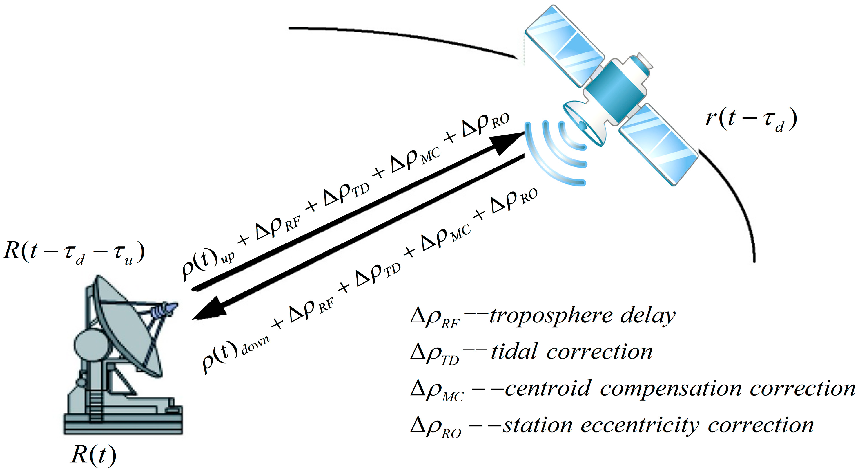
Figure 1 is the schematic diagram of the two-way ranging measurement for SLR. Where
and
are the upward distance and downward distance of the laser signal.
is the laser upbound time,
is the laser down-bound time,
is the position where the down-bound laser signal is received by the station at the time t,
is the position where the monitoring station transmits up-bound signals to the detector at the time
, and
is the position where the detector receives the laser uplink signal at the time
. Considering the correction value, the one-way calculated distance by SLR at time t is:
The residual of the SLR observations is: .
2.2. POD Strategies
The methodology of SLR-only POD is implemented by the dynamic orbit determination approach [
31]. The configuration of parameters of SLR-only orbit determination are shown in
Table 1. Moreover, the fundamental information and offsets of LRA’s effective phase center with respect to the Center of Mass (CoM) for BDS-3 satellites are shown in
Table 2.
The National University of Defense Technology orbit determination Toolkit (NUDTTK) software was used in this paper [
37,
38,
39]. Each arc section according to the number of NPs set the weight to avoid part of the station due to the role of fewer data being diminished. The external accuracy of the multi-day arc solutions was assessed by contrasting the difference with microwave-based orbits from WUM. At 15-min intervals, the orbital differences were broken down into RTN directions, and their corresponding daily RMS were determined using Equation (4):
where
is the total number of the orbit list,
is the SLR solution orbit’s position,
is the microwave-based orbit position.
If the RMS value of the orbit determination error exceeds the threshold of 1, 5, and 5 m in the R, T, and N directions for BDS-3 satellites, then it is considered a failure in the SLR-only orbit determination, and the RMS values of multi-day arc solutions are experimentally deleted. The efficiency of the orbit solutions is evaluated by comparing the number of successful SLR solutions to the total number of orbit solutions determined using microwave observations at WUM during the same period [
27].
3. BDS-3 POD Based on Actual SLR Observations
3.1. SLR Observations of BDS-3 Satellites
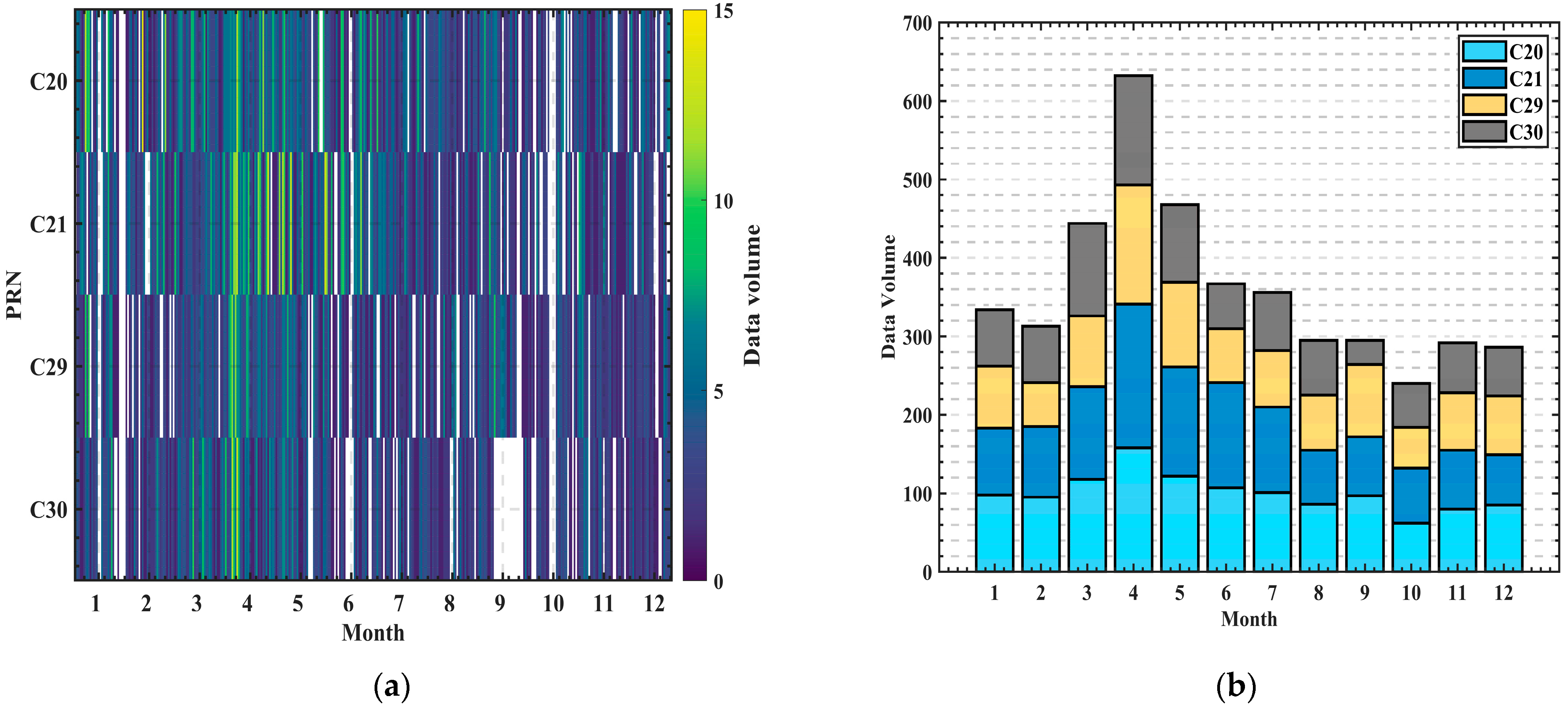
All available SLR NP observations of the consolidated laser ranging data (CRD) format for BDS-3 satellites in 2020 are provided by the ILRS, as shown in
Table 3 and
Figure 2. It can be seen that the number of SLR observations of the C20 and C21 satellites was more significant than those of C29 and C30, with an average of 10 NPs per day. C29 and C30 satellites had an average of 8 NPs per day. The number of observations in the first half of 2020 was significantly higher than in the second half of 2020. More than 350 arcs of comment on average per month can be guaranteed in total; in April, there were over 650 observation arcs. However, there were only 260 observation arcs in October.
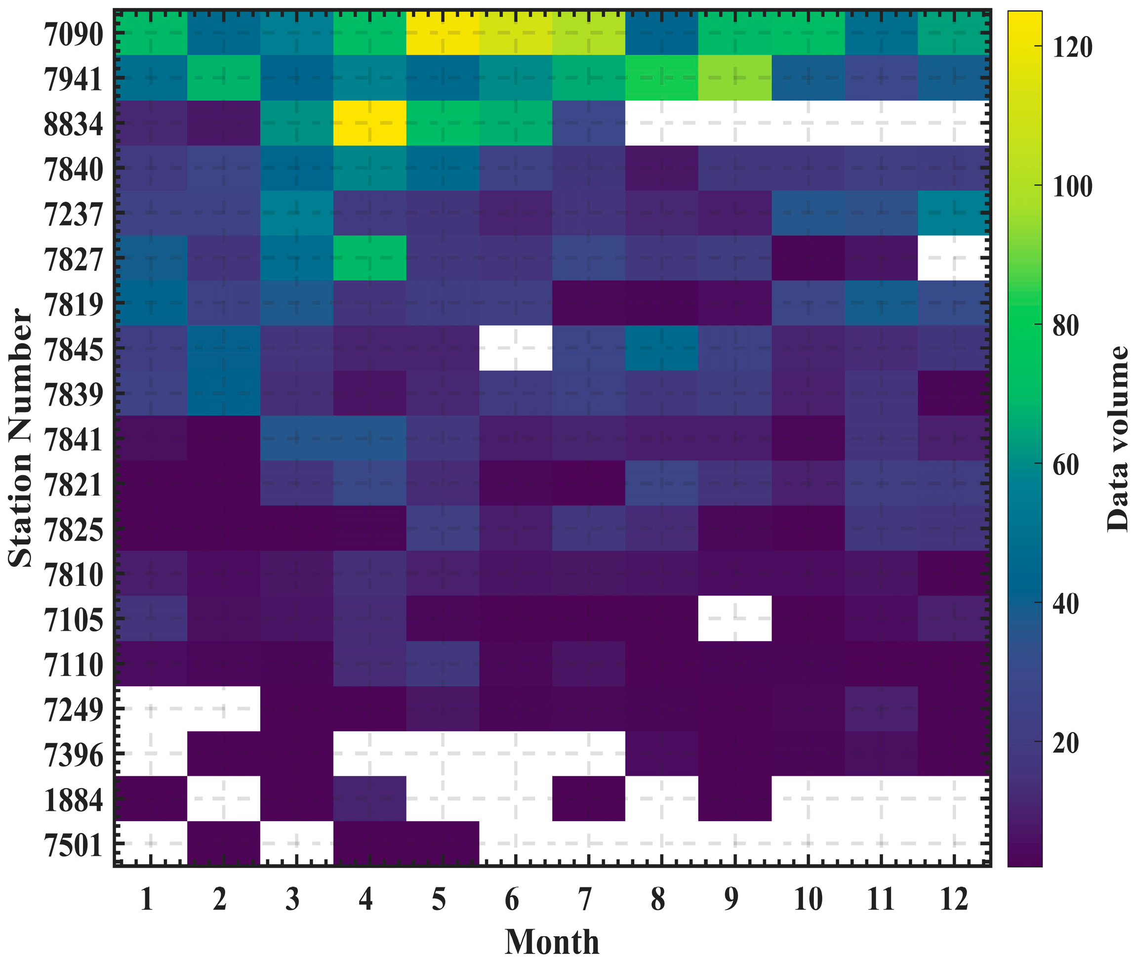
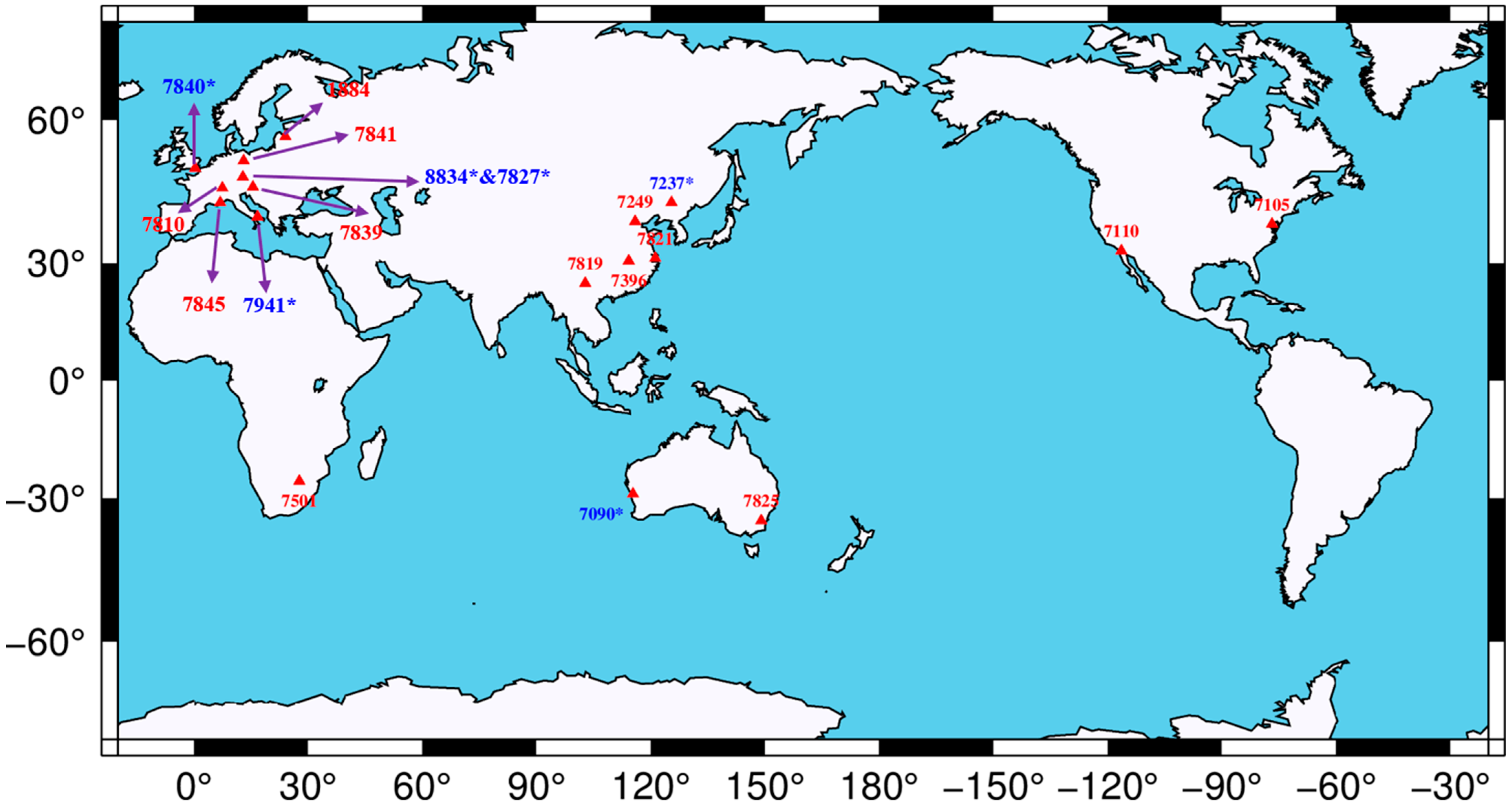
Figure 3 highlights the monthly contributions of each SLR station to the observations made by four BDS-3 satellites, and the distribution of SLR stations is depicted in
Figure 4. From
Figure 3, station 7090 from Australia provided the most observations. Moreover, five stations, including 7237 in China, 7840 in the United Kingdom, 7845 in France, 7941 in Italy, and 8834 in Germany, made significant contributions to the observations of BDS-3 satellites through their SLR measurements. However, some stations only observe BDS-3 satellites for a short period, such as 7396 in China, 1884 in Latvia, and 7501 in South Africa. Interestingly, station 8834 ceased providing SLR observations of BDS-3 after July 2020. According to
Figure 4, the majority of SLR observations of BDS-3 satellites are provided by stations in the Northern Hemisphere, including those located in China (7237, 7249, 7824, 7819, and 7396), Europe (7941, 7840, 8834, 7827, 7810, 7839, 7841, 1884, and 7845), and the United States (7110, 7105). Only three stations in the Southern Hemisphere contribute SLR observations, the 7090 station and the 7825 station, which are located in Australia, and 7501 in South Africa.
3.2. The Orbit Comparison with WUM Orbits
We validated the WUM orbits externally and eliminated the worst SLR observations, which can improve the precision and stability of the SLR-only orbit determination. In
Table 4, the percentage of qualified SLR observations is over 97.28% for all BDS-3 satellites, showing the number of available SLR observations of 2680–3512, respectively. The RMS of SLR residuals is 3.36–3.78 cm, and the mean offset is 0.42–2.78 cm for BDS-3 satellites.
The success efficiency and average accuracy of BDS-3 satellite SLR-only multi-day PODs are displayed in
Table 5. As the orbiting arc length increases, the efficiency of orbit determination solutions of all satellites increases significantly. When the length of the or-biting arc is three days, the POD success efficiency is only about 50%, while the arc length of 5 days can be increased to 80%. The efficiency is similar for 7-day and 9-day arc solutions. In the 9-day arc length, for C20 and C21 satellites, it is possible to determine a reliable orbit solution above 97.2–98.0% and above 91.3–94.1% for C29 and C30 satellites.
Figure 5 depicts the average POD accuracy at various orbiting arc lengths, with the highest accuracy of a 9-day arc length. About 1 m of POD accuracy can be obtained in a 5-day arc length. The POD accuracy improves from 1–2 m at a 3-day arc length to 0.5–1 m at a 9-day arc length.
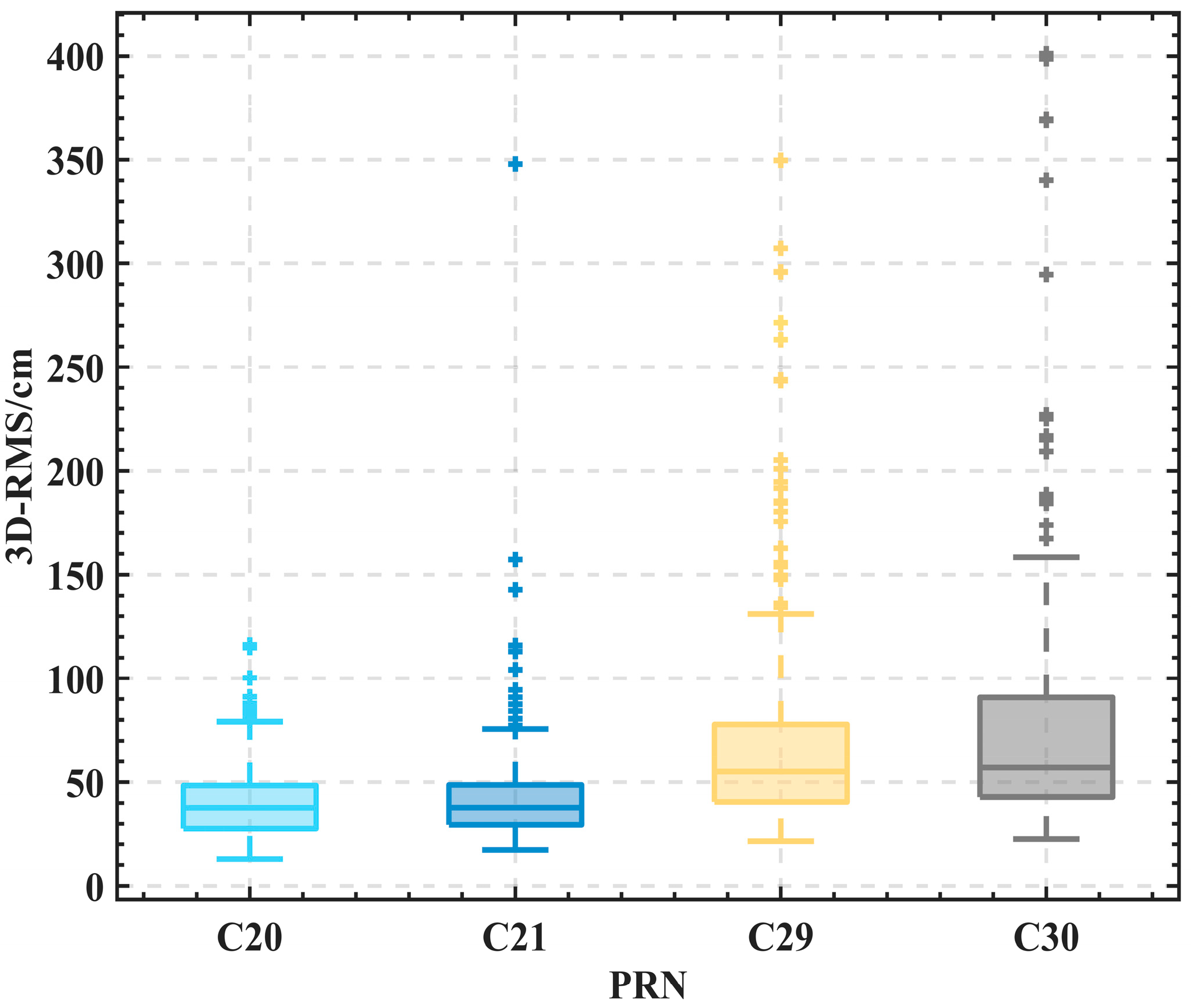
Table 6 gives the results of the 9-day POD. In the statistical results of the median RMS, the C20 and C21 satellite orbit accuracies in the 3D direction were better than 40 cm, while those of the C29 and C30 satellites were between 50 and 60 cm. The median orbit RMS of all BDS-3 in the R direction was below 10 cm, and the C20 and C21 satellites can even achieve 5 cm.
Figure 6 shows the box plots for the four BDS-3 satellites under the 9-day solution, with the solid line in the box representing the median RMS; the first (Q1) and third (Q3) quartiles are denoted by the bottom and top lines of the box, respectively. The box’s height indicates the interquartile range (IQR). The value of Q3 + 1.5 IQR and Q1 − 1.5 IQR is indicated by the top and bottom whiskers, respectively.
Figure 6 demonstrates that C20 and C21 satellites have a more consistent POD accuracy, with most solutions within 50 cm. In contrast, the accuracy of the C29 and C30 satellites is less accurate, mainly due to specific solutions being above 150 cm. The quantity of SLR observations and the distribution of observation stations could be the leading causes of this discrepancy.
3.3. The Dependency on the Number of SLR Observations and SLR Stations
Figure 7 depicts how the quantity of SLR observations in 9-day arc solutions influences RMS in RTN directions. The maximum number of SLR observation arcs for all four BDS-3 satellites exceeds 60 in 9-day arc solutions. However, at least 10 SLR observation arcs are required to obtain an orbit successfully. With more than 20 SLR observation arcs, the orbit accuracy considerably increases and improves, especially in the T and N directions. The orbital accuracy increases slightly when there are 30 or more SLR observation arcs.
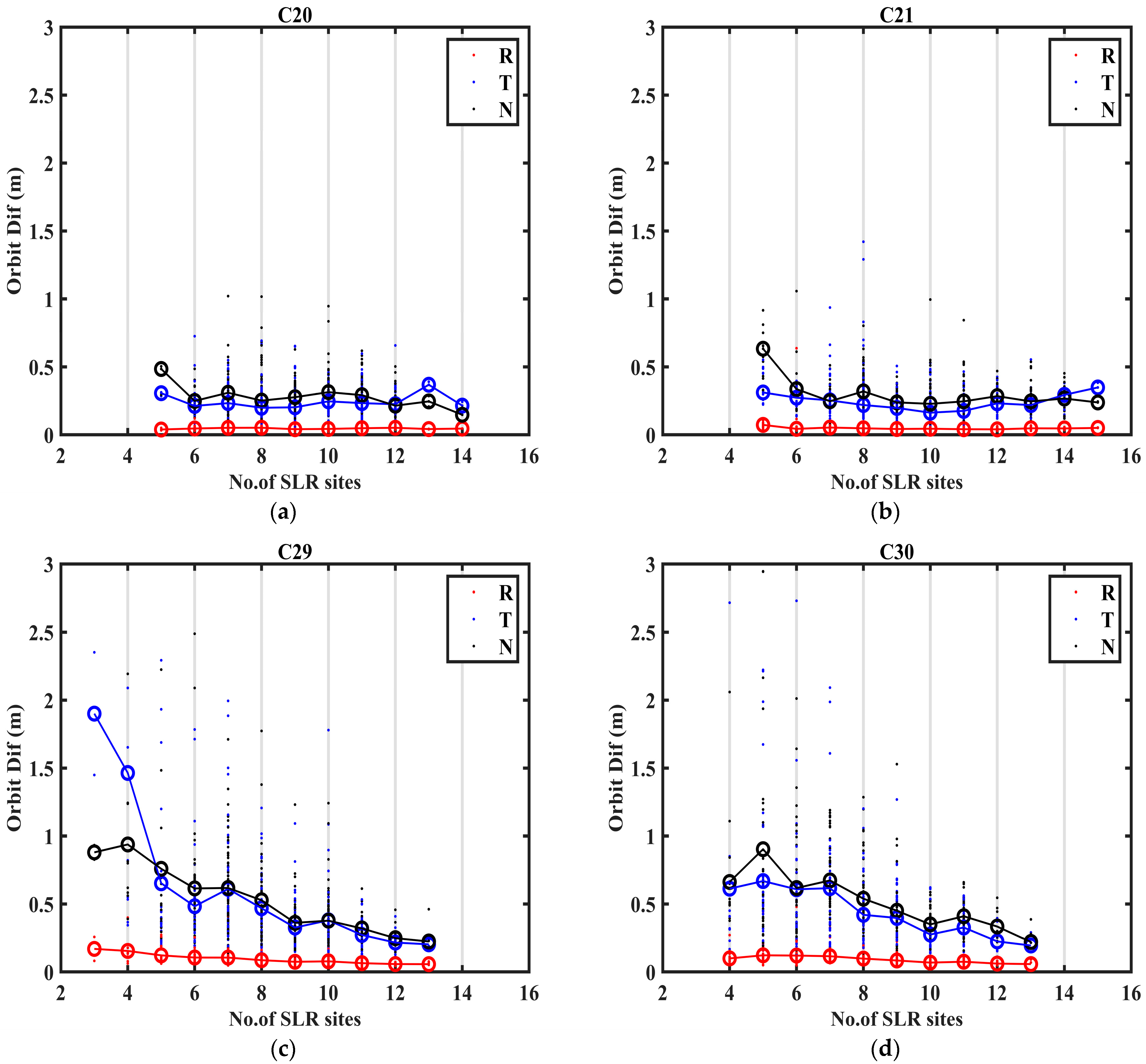
Figure 8 shows how the RMS for 9-day solutions depends on the number of SLR stations. The C20 and C21 satellites have a maximum of 14–15 SLR stations, and there are 13 SLR stations for the C29 and C30 satellites in their 9-day arc, respectively. At least 3–5 SLR stations are necessary to determine an orbit effectively. Additionally, the accuracy of the multi-day arc solutions increases with the number of SLR stations. For C20 and C21 satellites, the POD results improve and become steadier when there are more than 6–8 SLR stations. The geographic distribution geometry of SLR stations is strengthened as the number of SLR stations rises, improving the accuracy of the SLR-only orbit determination, particularly in the T and N directions, especially for C29 and C30 satellites.
4. Simulation Analysis of BDS-3 POD Accuracy
The SLR observations contain inevitable measurement errors (random and systematic errors). This section explores how measurement errors and orbit model errors affect the accuracy of POD using simulated data and the same number of actual observations.
4.1. SLR Observations Simulation Processing Strategy
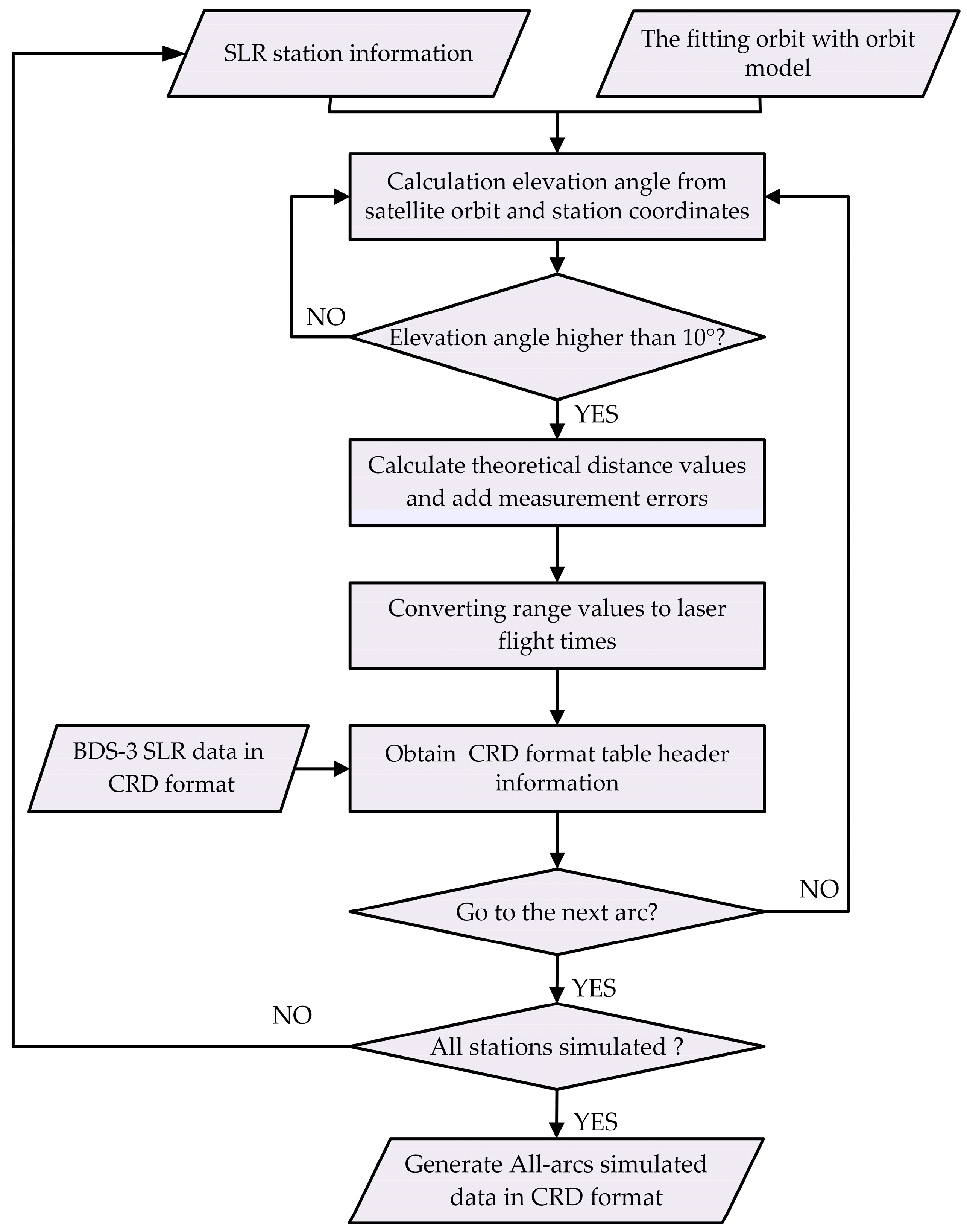
The observations of BDS-3 satellites were simulated with the fitting orbit [
40,
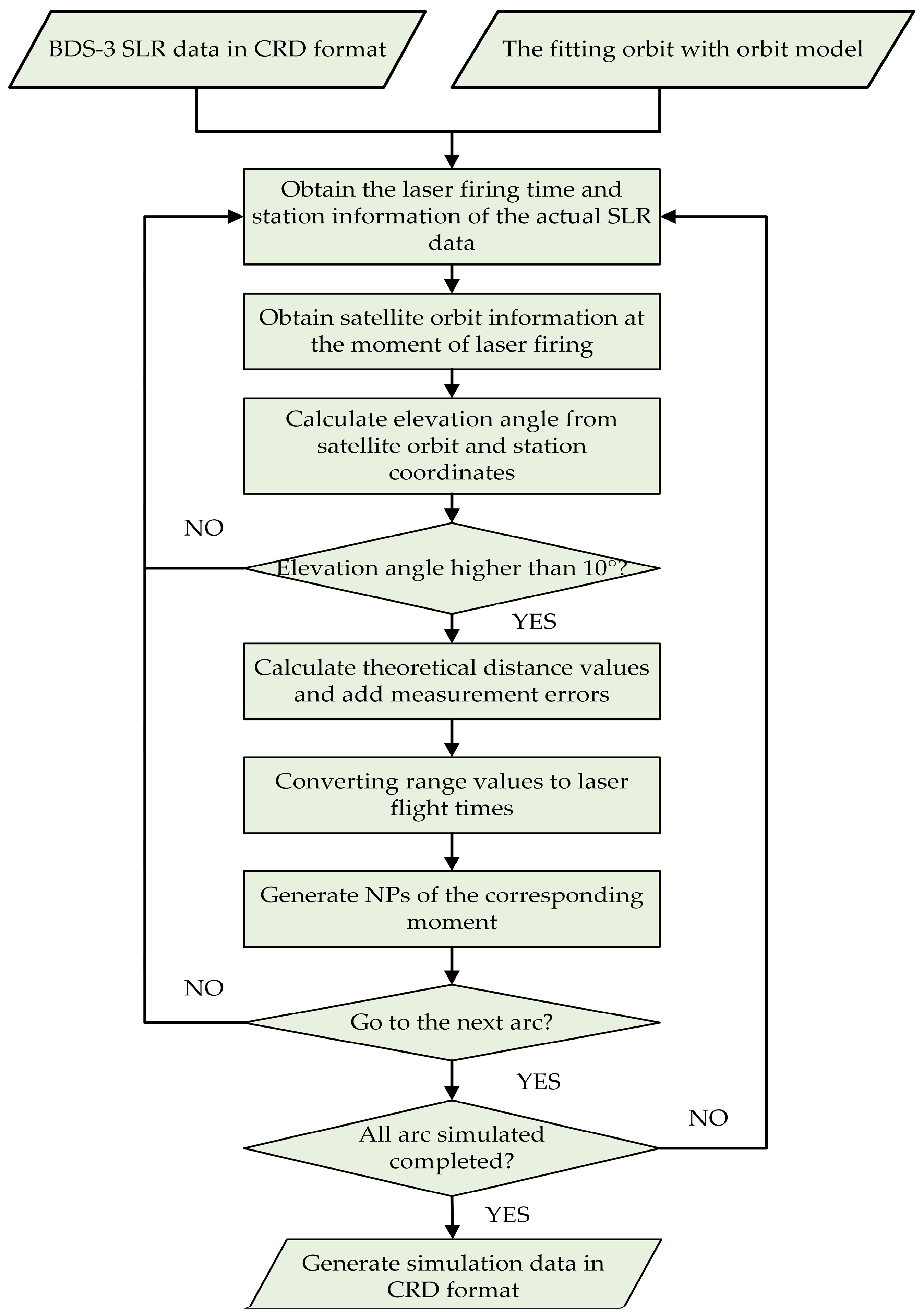
41] and the actual observations of BDS-3 satellites in 2020 to ensure that the moments and the number of SLR simulation arcs correspond to the actual SLR observations. The simulation process is depicted in
Figure 9 in CRD format. The fitting orbit refers to the orbit obtained by fitting the WUM orbit with the orbital dynamics model. The purpose of using the fitting orbit as the reference orbit for simulated orbit determination is to ensure that the orbit dynamics model used in the simulated orbit determination is consistent with the dynamic model of the fitting orbit. Compared to the fitting orbit, the POD results for the 9-day solution were 0.7 mm for C20 and C21 satellites and 0.9 mm for C29 and C30 satellites when no measurement error was applied to the simulated data. The performance proves the correctness of the simulation idea.
4.2. Dependency on the Measurement Errors
To discuss the effect of measurement error on the accuracy of orbit determination, the reference orbit should be ‘the orbit determined using the simulated clean SLR observations (without measurement errors)’. The 3D RMS of BDS-3 satellites is displayed in
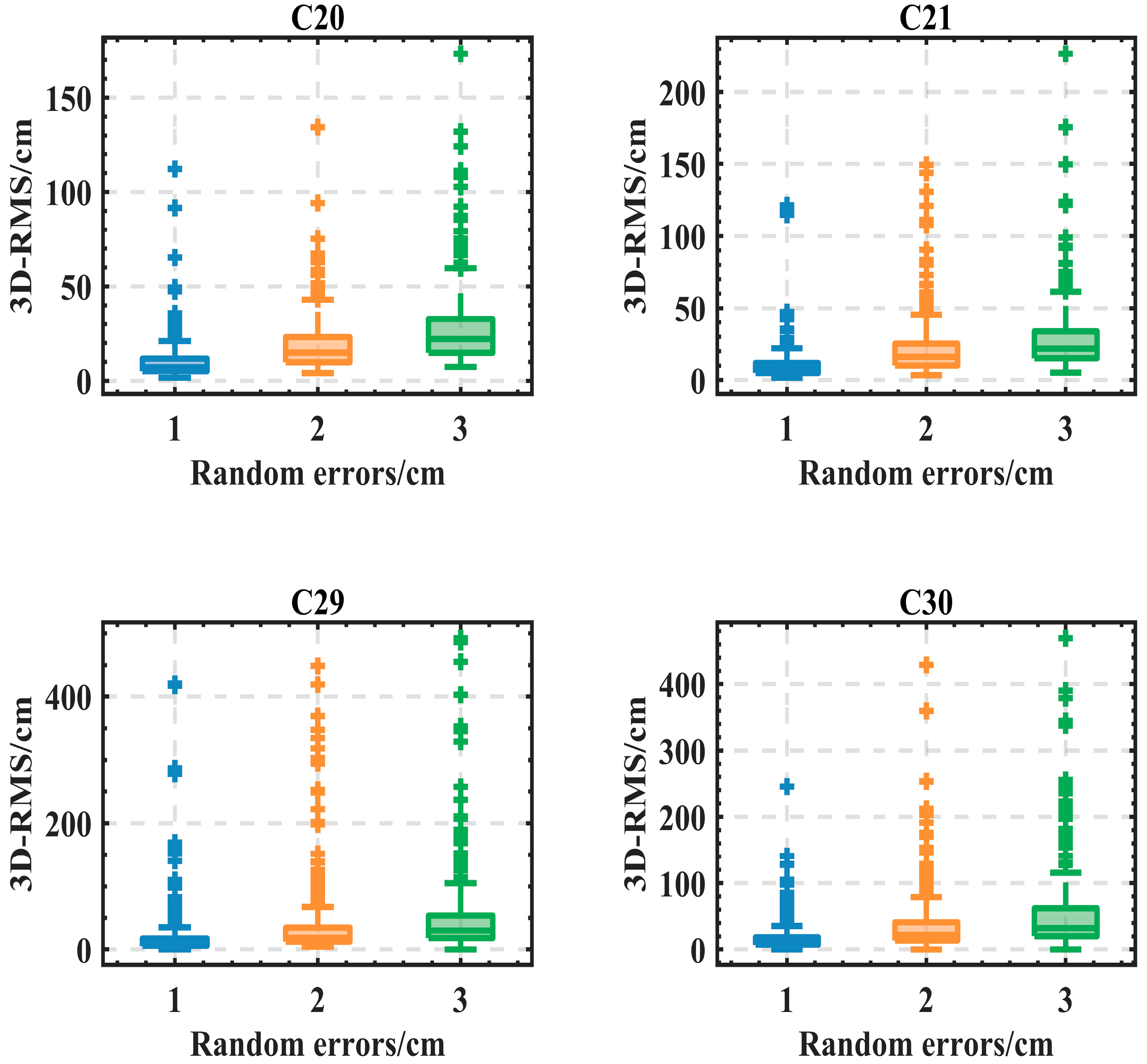
Figure 10, with the nine-day data adjusted for 1–3 cm random errors (Gaussian white noise). The results indicate that increasing the random error resulted in decreased orbit accuracy. For example, the median orbit accuracy of BDS-3 satellites was between 7.1 and 10.8 cm when there was 1 cm of random error, 15.0–22.3 cm under 2 cm of random error, and 21.8–32.6 cm under 3 cm of random error.
The accuracy of SLR measurements is limited by uncorrected systematic errors in the stations, resulting from various sources such as calibration and synchronization procedures, hardware malfunction, and nonlinearities in the time-of-flight measurement devices [
29]. According to information from
https://ilrs.cddis.eosdis.nasa.gov/science/qcb/ (accessed on 1 January 2023), these errors typically range from 3 to 30 mm. To investigate the impact of systematic errors on POD accuracy, we conducted an analysis where we introduced systematic errors of 1–3 cm at each SLR station. According to Strugarek et al. [
42], the SLR residuals show a constant value for the time series dependence of different SLR stations. Therefore, this paper added the constant value with a random positive or damaging to the observations of different stations as the systematic error. However, it is worth mentioning that the systematic errors were the same for the observations of the same station.
Figure 11 shows the POD accuracy.
Figure 11 demonstrates that, as systematic errors increased, there was a decrease in orbit accuracy. For illustration, the median orbit accuracy of BDS-3 satellites was between 9.9 and 14.6 cm under 1 cm of systematic error, 20.3–29.6 cm under 2 cm of systematic error, and 30.6–46.3 cm under 3 cm of systematic error.
Table 7 and
Table 8 illustrate the impact of a 1 cm random error or systematic error on the POD accuracy of BDS-3 satellites.
Table 7 shows that each cm of random error affects the POD accuracy in the R-direction by approximately 0.7–1 cm and affects the orbit accuracy in the 3D-direction range of 7.3–11.0 cm.
Table 8 shows that each 1 cm of systematic error affects the orbit accuracy in the R-direction by approximately 1.1–1.5 cm and affects the orbit accuracy in the 3D-direction in the range of 10.1–15.0 cm. In general, it is related to the observational density of the satellite.
4.3. Dependency on the SRP Errors
The BDS-3 satellite is subject to various conservative and non-conservative forces during its motion around the Earth. The non-conservative force—SRP—is complex to model, and its acceleration can reach the order of 10−7 m/s2, which is the most important influential factor of the orbital model accuracy. In this section, we examine the impact of SRP errors on the precision of orbit determination for the BDS-3 satellite. The detailed simulation idea is as follows:
Fit 1-day orbit individually, 9 days in total, calculate and stitch together their SRP a1;
Fit 9-day orbits and calculate their SRP a2;
Calculate the SRP influence factor C (Equation (5)), and compute the RMS for each direction at the current time;
- 4.
Add the SRP influence factor C according to the current date in the orbit determination simulation as the SRP errors;
- 5.
Calculate the magnitude of the SRP influence factor:
Table 9 shows the median SRP influence factor of BDS-3 satellites in 2020. The influence factors for the satellites of different agencies (CAST and SECM) differed from 1.6–1.8% in x, 2.5–2.8% in y, and 7.8–7.9% in z for C20 and C21 satellites to 3.7–3.9% in x, 3.8–4.2% in y, and 9.8–9.9% in z for C29 and C30 satellites, respectively. For SRP influence magnitude, it was 0.6% for C20 and C21 satellites and 2.0–2.1% for C29 and C30 satellites, respectively.
Table 10 reveals how SRP errors affect orbit accuracy in the R, T, and N directions. Under SRP error influence, the C20 and C21 satellite orbit determination accuracy was 21.7 and 20.5 cm, respectively. For C29 and C30 satellite POD accuracy, it increased to 45.1 and 43.3 cm. This effect may stem from the SRP influence factor and the number of SLR observations.
5. Discussion
The POD of GNSS satellites using SLR has received less attention than that using GNSS microwaves. However, when enough SLR observations are available, SLR may significantly improve the POD accuracy of GNSS satellites. It is influenced by the quantity of SLR observations, SLR station locations, and measurement errors of SLR observations. With the assistance of 7–9 days of observations, the accuracy of BDS-3 satellite orbit determination can reach the centimeter level in the R direction even without so many SLR stations and SLR observations.
For the SLR simulation data with the same observation density, systematic errors deteriorated orbit determination accuracy more than random errors. However, if the number of SLR simulation data is sufficient (only considering that the SLR station is visible to the satellite on the geometric connections, the detailed simulation process is shown in
Figure 12), then the impact of 1 cm random error on POD accuracy is in the order of millimeters, and the impact of systematic errors is close to its value. Meanwhile, the result of SRP errors decreased to 12.0 cm for C20 and C21 satellites and 19.2–20.5 cm for C29 and C30 satellites, respectively. This is caused by the SRP influence factor (
Table 8).
6. Conclusions
This paper explored the quality of POD for BDS-3 satellite multi-day arc solutions for a year starting at the beginning of 2020. It examined how the median RMS is influenced by the quantity of SLR data and the amount of SLR stations. Moreover, the effects of random, systematic, and SRP errors on the BDS-3 satellite’s POD results were examined using the SLR simulation data with the same observation density. The following are the preliminary conclusions:
Different BDS-3 satellites have an average of 53–69 SLR NPs per week, and the observation stations are concentrated in the Chinese and European regions. As the orbit arc length increases, the success efficiency and POD accuracy rise significantly. Compared to WUM precise orbits, the 9-day median RMS is estimated to be 4.7–8.2, 22.1–35.2, and 27.4–43.8 cm, respectively. This is a satisfactory result. Range measurements to BDS-3 satellites may aid in monitoring space debris since, for 9-day arc solutions, 20 observation arcs or five stations may provide an orbit with an accuracy of 1 m, which is enough for dormant navigation satellites equipped with LRAs. To obtain an orbital accuracy of around 0.5 m, 6–8 stations or 30–35 observation arcs are necessary.
For 9-day orbital arc lengths, the orbit accuracy decreased by 9.3–11.0 cm for every 1 cm of random errors, respectively. For every 10.1–15.0 cm of systematic error per centimeter, it impacted orbit accuracy. It is associated with the satellite’s observational density. The magnitude of SRP influence factors for different agencies’ satellites (CAST and SECM) differed from 0.6% for C20 and C21 satellites to 2.0–2.1% for C29 and C30 satellites, and the effect of orbit accuracy was 20.5–45.1 cm.
In summary, SLR can improve precision in this area due to its radial direction sensitivity. The along-track and cross-track directions, however, have significantly lesser accuracy. Despite its limits in determining GNSS satellite orbits, SLRs are compelling for science projects where orbital accuracy requirements are less demanding. In the future, SLR ought to be used with other techniques, such as GNSS and DORIS, to capitalize on their complementing advantages.
Author Contributions
Z.A., K.S. and D.G. provided the initial idea for this study. Z.A. and D.G. designed the experiments. Z.A. and C.W. performed the experiments. Z.A. and K.S. analyzed the data; D.G. contributed to the analysis tools. J.Z., C.W., L.T., Z.X., J.W. and D.L. gave valuable advice on the paper writing. All authors have read and agreed to the published version of the manuscript.
Funding
This research has been jointly funded by the Guangdong Major Project of Basic and Applied Basic Research (the funder is Luo Jun, No.2019B030302001) and the Guangdong Basic and Applied Basic Research Foundation (the funder is Shao Kai, No.2022A1515110236).
Data Availability Statement
The data used to support the findings of this study are available from the corresponding author upon request.
Acknowledgments
Thanks are due to ILRS, EDC, and WUM for providing the SLR data and orbits of BDS-3 satellites. The authors are grateful to Zheng Zhang, Ke An, and Zhen Fang for their insightful comments and conversations.
Conflicts of Interest
The authors declare no conflict of interest.
References
- Degnan, J.J.; Smith, D.E.; Smith, D.E.; Turcotte, D.L.; Turcotte, D.L. Millimeter accuracy Satellite Laser Ranging: A Review. Contrib. Space Geod. Geodyn. Technol. 1993, 25, 133–162. [Google Scholar] [CrossRef]
- Appleby, G.; Rodríguez, J.; Altamimi, Z. Assessment of the accuracy of Global Geodetic satellite laser ranging observations and estimated impact on ITRF scale: Estimation of systematic errors in LAGEOS observations 1993–2014. J. Geod. 2016, 90, 1371–1388. [Google Scholar] [CrossRef]
- An, Z.; Shao, K.; Gu, D.; Zhu, J.; Li, M.; Tong, L.; Wei, C. Simulation and accuracy analysis of orbit determination for TianQin using SLR data. Class. Quantum Gravity 2022, 39, 245016. [Google Scholar] [CrossRef]
- Müller, J.; Murphy, T.W.; Schreiber, U.; Shelus, P.J.; Torre, J.; Williams, J.G.; Boggs, D.H.; Bouquillon, S.; Bourgoin, A.; Hofmann, F. Lunar Laser Ranging: A tool for General relativity, Lunar Geophysics and Earth Science. J. Geod. 2019, 93, 2195–2210. [Google Scholar] [CrossRef]
- Zhang, C.; Gao, T.; Cao, Y.; Fan, Z.; Fu, H.; Gu, D.; Han, X.; Huang, Y.; Kang, L.; Li, K.; et al. The facilities and performance of TianQin laser ranging station. Class. Quantum Gravity 2022, 39, 125005. [Google Scholar] [CrossRef]
- Mao, D.; McGarry, J.F.; Mazarico, E.; Neumann, G.A.; Sun, X.; Torrence, M.H.; Zagwodzki, T.W.; Rowlands, D.D.; Hoffman, E.D.; Horvath, J.E.; et al. The laser ranging experiment of the Lunar Reconnaissance Orbiter: Five years of operations and data analysis. Icarus 2017, 283, 55–69. [Google Scholar] [CrossRef]
- Mazarico, E.; Neumann, G.A.; Barker, M.K.; Goossens, S.; Smith, D.E.; Zuber, M.T. Orbit determination of the Lunar Reconnaissance Orbiter: Status after seven years. Planet Space Sci. 2018, 162, 2–19. [Google Scholar] [CrossRef]
- Löcher, A.; Kusche, J. Assessment of the impact of one-way laser ranging on orbit determination of the Lunar Reconnaissance Orbiter. J. Geod. 2019, 93, 2421–2428. [Google Scholar] [CrossRef]
- Pearlman, M.; Degnan, J.J.; Bosworth, J.M. The International Laser Ranging Service. Adv. Space Res. 2002, 2, 135–143. [Google Scholar] [CrossRef]
- Wilkinson, M.; Schreiber, U.; Procházka, I.; Moore, C.; Degnan, J.; Kirchner, G.; Zhongping, Z.; Dunn, P.; Shargorodskiy, V.; Sadovnikov, M.; et al. The next generation of satellite laser ranging systems. J. Geod. 2019, 93, 2227–2247. [Google Scholar] [CrossRef]
- Pearlman, M.R.; Noll, C.E.; Pavlis, E.C.; Lemoine, F.G.; Combrink, L.; Degnan, J.J.; Kirchner, G.; Schreiber, U. The ILRS: Approaching 20 years and planning for the Future. J. Geod. 2019, 93, 2161–2180. [Google Scholar] [CrossRef]
- Pearlman, M.; Noll, C.; Torrence, M.; NASA; GSFC. Results from ILRS GNSS tracking campaigns. In Proceedings of the 2015 ILRS Technical Workshop, Matera, Italy, 26–30 October 2015. [Google Scholar]
- Li, X.; Yuan, Y.; Zhu, Y.; Jiao, W.; Bian, L.; Li, X.; Zhang, K. Improving BDS-3 precise orbit determination for Medium Earth Orbit satellites. GPS Solut. 2020, 24, 53. [Google Scholar] [CrossRef]
- Sośnica, K.; Thaller, D.; Dach, R.; Steigenberger, P.; Beutler, G.; Arnold, D.; Jäggi, A. Satellite laser ranging to GPS and GLONASS. J. Geod. 2015, 89, 725–743. [Google Scholar] [CrossRef] [Green Version]
- Sośnica, K.; Prange, L.; Kaźmierski, K.; Bury, G.; Drożdżewski, M.; Zajdel, R.; Hadas, T. Validation of Galileo orbits using SLR with a focus on satellites launched into incorrect orbital planes. J. Geod. 2018, 92, 131–148. [Google Scholar] [CrossRef] [Green Version]
- Yang, H.; Xu, T.; Nie, W.; Gao, F.; Guan, M. SLR validation and evaluation on BDS precise orbits from 2013 to 2018. Adv. Space Res. 2019, 64, 475–490. [Google Scholar] [CrossRef]
- Tao, E.; Guo, N.; Xu, K.; Wang, B.; Zhou, X. Validation of Multi-Year Galileo Orbits Using Satellite Laser Ranging. Remote Sens. 2021, 13, 4634. [Google Scholar] [CrossRef]
- Ye, F.; Yuan, Y.; Yang, Z. Validation and evaluation on B1Ib3I-based and B1Cb2a-based BDS-3 precise orbits from IGMAS. Adv. Space Res. 2022, 70, 2167–2177. [Google Scholar] [CrossRef]
- Zajdel, R.; Sośnica, K.; Bury, G. A new online service for the validation of Multi-GNSS orbits using SLR. Remote Sens. 2017, 9, 1049. [Google Scholar] [CrossRef] [Green Version]
- Bury, G.; Sośnica, K.; Zajdel, R.; Strugarek, D.; Hugentobler, U. Determination of precise Galileo orbits using combined GNSS and SLR observations. GPS Solut. 2021, 25, 11. [Google Scholar] [CrossRef]
- Yang, H.; Xu, T.; Nie, W.; Fang, Z.; Li, M.; Guan, M. GLONASS precise orbit determination based on L-band and SLR data. Meas. Sci. Technol. 2021, 32, 45007. [Google Scholar] [CrossRef]
- Urschl, C.; Beutler, G.; Gurtner, W.; Hugentobler, U.; Schaer, S. Contribution of SLR tracking data to GNSS orbit determination. Adv. Space Res. 2007, 39, 1515–1523. [Google Scholar] [CrossRef]
- Yang, Y.; Xu, Y.; Li, J.; Yang, C. Progress and performance evaluation of Beidou Global Navigation Satellite System: Data analysis based on BDS-3 demonstration system. Sci. China Earth Sci. 2018, 61, 614–624. [Google Scholar] [CrossRef]
- Yang, Y.; Gao, W.; Guo, S.; Mao, Y.; Yang, Y. Introduction to Beidou-3 Navigation Satellite System. Navigation 2019, 66, 7–18. [Google Scholar] [CrossRef] [Green Version]
- Zhao, G.; Zhou, S.; Zhou, X.; Wu, B. Precise Orbit Determination of Beidou Satellites Using Satellite Laser Ranging; Springer: Berlin/Heidelberg, Germany, 2013; pp. 221–229. [Google Scholar] [CrossRef]
- Bury, G.; Sośnica, K.; Zajdel, R. Multi-GNSS orbit determination using satellite laser ranging. J. Geod. 2019, 93, 2447–2463. [Google Scholar] [CrossRef] [Green Version]
- Yang, H.; Xu, T.; Nie, W.; Gao, F.; Guan, M. Precise orbit determination of BDS-2 and BDS-3 using SLR. Remote Sens. 2019, 11, 2735. [Google Scholar] [CrossRef] [Green Version]
- Hugentobler, U. Innovation: Laser ranging to GNSS satellites. GPS World 2017, 28, 5–42. [Google Scholar]
- Luceri, V.; Pirri, M.; Rodríguez, J.; Appleby, G.; Pavlis, E.C.; Müller, H. Systematic errors in SLR data and their impact on the ILRS products. J. Geod. 2019, 93, 2357–2366. [Google Scholar] [CrossRef]
- Wang, C.; Guo, J.; Zhao, Q.; Liu, J. Solar Radiation Pressure models for Beidou-3 I2-S satellite: Comparison and augmentation. Remote Sens. 2018, 10, 118. [Google Scholar] [CrossRef] [Green Version]
- Hackel, S.; Montenbruck, O.; Steigenberger, P.; Balss, U.; Gisinger, C.; Eineder, M. Model improvements and validation of Terrasar-X precise orbit determination. J. Geod. 2017, 91, 547–562. [Google Scholar] [CrossRef]
- William, M.; Folkner, J.G.W.D.; Ryan, S.; Park, A.P.K. The Planetary and Lunar Ephemerides De430 and De431. Interplanet. Netw. Prog. Rep. 2014, 196, 42–196. [Google Scholar]
- Beutler, G.; Brockmann, E.; Gurtner, W.; Hugentobler, U.; Mervart, L.; Rothacher, M. Extended orbit modeling techniques at the code processing center of the International GPS Service for Geodynamics (IGS): Theory and Initial Results. Manuscr. Geod. 1994, 19, 367–386. [Google Scholar]
- Petit, G.; Luzum, B. IERS Conventions. (IERS Technical Note; No. 36) Frankfurt am Main: Verlag des Bundesamts für Kartographie und Geodäsie; IERS Technical Note: Frankfurt, Germany, 2010; p. 179. [Google Scholar]
- Altamimi, Z.; Rebischung, P.; Métivier, L.; Collilieux, X. The International Terrestrial Reference Frame: Lessons from ITRF2014. Rend. Lincei. Sci. Fis. E Nat. 2018, 29 (Suppl. S1), 23–28. [Google Scholar] [CrossRef]
- Sośnica, K. LAGEOS sensitivity to Ocean Tides. Acta Geophys. 2015, 63, 1181–1203. [Google Scholar] [CrossRef] [Green Version]
- Ju, B.; Gu, D.; Herring, T.A.; Allende-Alba, G.; Montenbruck, O.; Wang, Z. Precise orbit and baseline determination for maneuvering Low Earth Orbiters. Gps Solut. 2017, 21, 53–64. [Google Scholar] [CrossRef] [Green Version]
- Shao, K.; Gu, D.; Ju, B.; Wang, W.; Wei, C.; Duan, X.; Wang, Z. Analysis of Tiangong-2 orbit determination and prediction using onboard dual-frequency GNSS data. GPS Solut. 2020, 24, 11. [Google Scholar] [CrossRef]
- Gu, D.; Ju, B.; Liu, J.; Tu, J. Enhanced GPS-based Grace baseline determination by using a new strategy for ambiguity resolution and relative phase center variation corrections. Acta Astronaut. 2017, 138, 176–184. [Google Scholar] [CrossRef]
- Li, M.; Lei, Z.; Li, W.; Jiang, K.; Wang, Y.; Zhao, Q. Calibration of Grace on-board accelerometers for Thermosphere Density Derivation. GEO-Spat. Inf. Sci. 2022, 25, 74–87. [Google Scholar] [CrossRef]
- Vielberg, K.; Forootan, E.; Lück, C.; Löcher, A.; Kusche, J.; Börger, K. Comparison of accelerometer data calibration methods used in Thermospheric Neutral Density Estimation. Ann. Geophys. 2018, 36, 761–779. [Google Scholar] [CrossRef] [Green Version]
- Strugarek, D.; Sośnica, K.; Arnold, D.; Jäggi, A.; Zajdel, R.; Bury, G. Satellite laser ranging to GNSS-based Swarm orbits with handling of systematic errors. GPS Solut. 2022, 26, 761–779. [Google Scholar] [CrossRef]
Figure 1.
Schematic diagram of the two-way ranging measurement for SLR.
Figure 1.
Schematic diagram of the two-way ranging measurement for SLR.
Figure 2.
The daily (a) and monthly SLR observations (b) of BDS-3 provided by ILRS in 2020.
Figure 2.
The daily (a) and monthly SLR observations (b) of BDS-3 provided by ILRS in 2020.
Figure 3.
The contribution of each SLR station to the monthly SLR observations of BDS-3 satellites.
Figure 3.
The contribution of each SLR station to the monthly SLR observations of BDS-3 satellites.
Figure 4.
The distribution of BDS-3 satellite SLR observation stations in 2020 (‘blue and *’ stations refer to the 6 stations that contribute a large number of SLR observations).
Figure 4.
The distribution of BDS-3 satellite SLR observation stations in 2020 (‘blue and *’ stations refer to the 6 stations that contribute a large number of SLR observations).
Figure 5.
The overall average 3D-RMS of SLR-only PODs.
Figure 5.
The overall average 3D-RMS of SLR-only PODs.
Figure 6.
Box-plots for the four BDS-3 satellites under the 9-day solution.
Figure 6.
Box-plots for the four BDS-3 satellites under the 9-day solution.
Figure 7.
The relationship between the number of SLR observations and the median RMS values is shown by the red, blue, and black dots, which correspond to the RMS values in the R, T, and N directions, respectively. In addition, the median RMS values are indicated by a hollow circle, with a step size of 2. Subplot (a–d) represents C20, C21, C29, and C30 satellites, respectively.
Figure 8.
The relationship between the number of stations and the median RMS values. The definitions of different color dots and circles are the same as in
Figure 7. Subplot (
a–
d) represents C20, C21, C29, and C30 satellites, respectively.
Figure 8.
The relationship between the number of stations and the median RMS values. The definitions of different color dots and circles are the same as in
Figure 7. Subplot (
a–
d) represents C20, C21, C29, and C30 satellites, respectively.
Figure 9.
The simulation process of SLR data based on actual observations.
Figure 9.
The simulation process of SLR data based on actual observations.
Figure 10.
BDS-3 satellites simulated POD accuracy (with random errors).
Figure 10.
BDS-3 satellites simulated POD accuracy (with random errors).
Figure 11.
BDS-3 satellites simulated POD accuracy (with systematic errors).
Figure 11.
BDS-3 satellites simulated POD accuracy (with systematic errors).
Figure 12.
The simulation process of SLR data based on all-arcs observation.
Figure 12.
The simulation process of SLR data based on all-arcs observation.
Table 1.
The configuration of parameters of SLR-only orbit determination.
Table 1.
The configuration of parameters of SLR-only orbit determination.
| Project | Parameters and Models |
|---|
| Observe Elevation Angle Threshold | 10° |
| Threshold Residuals of SLR Observations | 300 mm |
| Earth Gravity Field | GGM05S, 120 × 120 |
| N-body Perturbation | JPL DE430 [32] |
| SRP | ECOM 9 [33] |
| Precession and Nutation | IERS2010 [34] |
| A priori Station Coordinates | ITRF2014 [35] |
| Pole and Ocean tides | CSR4.0 [36] |
| Relativistic Perturbation | Only Schwarzschild |
| A priori Orbital Parameters | The Precise Orbit of WUM |
| Orbital Parameters | 6 Orbital Element and 9 ECOM SRP |
Table 2.
The fundamental information and offsets of LRA’s effective phase center with respect to CoM for BDS-3 satellites [
13].
Table 2.
The fundamental information and offsets of LRA’s effective phase center with respect to CoM for BDS-3 satellites [
13].
| Pseudo-Random Noise (PRN) Number | PCOX (mm) | PCOY (mm) | PCOZ (mm) |
|---|
| C20 | 594.7 | −86.4 | 1264.4 |
| C21 | 598.6 | −86.6 | 1265.0 |
| C29 | 664.6 | 424.9 | 642.7 |
| C30 | 664.6 | 424.9 | 642.7 |
Table 3.
The number of SLR observation arcs and NPs of BDS-3 satellites in 2020.
Table 3.
The number of SLR observation arcs and NPs of BDS-3 satellites in 2020.
| PRN | Observations |
|---|
| Arcs | NPs |
|---|
| C20 | 1209 | 3492 |
| C21 | 1211 | 3566 |
| C29 | 988 | 2846 |
| C30 | 914 | 2755 |
Table 4.
The number of available SLR NPs, the proportion of the available SLR NPs, and the mean/RMS for SLR validation residuals (unit: cm).
Table 4.
The number of available SLR NPs, the proportion of the available SLR NPs, and the mean/RMS for SLR validation residuals (unit: cm).
| PRN | Available NPs | Proportion | Overall |
|---|
| C20 | 3476 | 99.37% | 2.78/3.77 |
| C21 | 3512 | 98.49% | 2.68/3.71 |
| C29 | 2810 | 98.74% | 1.18/3.78 |
| C30 | 2680 | 97.28% | 0.42/3.36 |
Table 5.
The success efficiency and average 3D-RMS of SLR-only PODs.
Table 5.
The success efficiency and average 3D-RMS of SLR-only PODs.
| PRN | The Success Efficiency of POD Solutions (Unit: %) | Average 3D-RMS (Unit: m) |
|---|
| 3 d | 5 d | 7 d | 9 d | 3 d | 5 d | 7 d | 9 d |
|---|
| C20 | 62.8 | 87.3 | 96.4 | 97.2 | 1.29 | 0.72 | 0.51 | 0.40 |
| C21 | 59.2 | 88.1 | 95.6 | 98.0 | 1.08 | 0.75 | 0.48 | 0.42 |
| C29 | 51.0 | 79.6 | 90.8 | 94.1 | 1.51 | 0.96 | 0.79 | 0.69 |
| C30 | 45.6 | 77.1 | 88.6 | 91.3 | 1.56 | 1.06 | 0.89 | 0.75 |
Table 6.
The median RMS of 9-day solutions (Unit: cm).
Table 6.
The median RMS of 9-day solutions (Unit: cm).
| PRN | VS WUM |
|---|
| R | T | N | 3D |
|---|
| C20 | 4.8 | 22.1 | 27.9 | 37.7 |
| C21 | 4.7 | 22.2 | 27.4 | 37.8 |
| C29 | 7.9 | 35.2 | 41.0 | 55.1 |
| C30 | 8.2 | 33.2 | 43.8 | 57.0 |
Table 7.
The impact of 1 cm random error on simulated POD accuracy (unit: cm).
Table 7.
The impact of 1 cm random error on simulated POD accuracy (unit: cm).
| PRN | R | T | N | 3D |
|---|
| C20 | 0.7 | 4.9 | 5.1 | 7.3 |
| C21 | 0.7 | 4.9 | 5.2 | 7.6 |
| C29 | 0.9 | 6.4 | 6.9 | 9.9 |
| C30 | 1.0 | 6.9 | 8.0 | 11.0 |
Table 8.
The impact of 1 cm systematic error on simulated POD accuracy (unit: cm).
Table 8.
The impact of 1 cm systematic error on simulated POD accuracy (unit: cm).
| PRN | R | T | N | 3D |
|---|
| C20 | 1.1 | 6.8 | 7.5 | 10.4 |
| C21 | 1.1 | 6.4 | 7.2 | 10.1 |
| C29 | 1.3 | 8.7 | 10.1 | 14.1 |
| C30 | 1.5 | 9.2 | 10.7 | 15.0 |
Table 9.
The median SRP influence factor of BDS-3 satellites (unit: %).
Table 9.
The median SRP influence factor of BDS-3 satellites (unit: %).
| PRN | SRP Influence Factor |
|---|
| X | Y | Z | Magnitude |
|---|
| C20 | 1.8 | 2.5 | 7.9 | 0.6 |
| C21 | 1.6 | 2.8 | 7.8 | 0.6 |
| C29 | 3.9 | 3.8 | 9.8 | 2.0 |
| C30 | 3.7 | 4.2 | 9.9 | 2.1 |
Table 10.
The impact of SRP errors on orbit accuracy in the R, T, and N directions (unit: cm).
Table 10.
The impact of SRP errors on orbit accuracy in the R, T, and N directions (unit: cm).
| PRN | VS Orbit Modeling Fitting Orbit |
|---|
| R | T | N | 3D |
|---|
| C20 | 2.0 | 14.8 | 13.9 | 21.7 |
| C21 | 2.0 | 14.5 | 14.1 | 20.5 |
| C29 | 4.5 | 32.8 | 25.2 | 45.1 |
| C30 | 4.4 | 30.8 | 25.3 | 43.3 |
| Disclaimer/Publisher’s Note: The statements, opinions and data contained in all publications are solely those of the individual author(s) and contributor(s) and not of MDPI and/or the editor(s). MDPI and/or the editor(s) disclaim responsibility for any injury to people or property resulting from any ideas, methods, instructions or products referred to in the content. |
© 2023 by the authors. Licensee MDPI, Basel, Switzerland. This article is an open access article distributed under the terms and conditions of the Creative Commons Attribution (CC BY) license (https://creativecommons.org/licenses/by/4.0/).


 ,
, 


